EP3015611A1 - Lavatory drain - Google Patents
Lavatory drain Download PDFInfo
- Publication number
- EP3015611A1 EP3015611A1 EP15192465.1A EP15192465A EP3015611A1 EP 3015611 A1 EP3015611 A1 EP 3015611A1 EP 15192465 A EP15192465 A EP 15192465A EP 3015611 A1 EP3015611 A1 EP 3015611A1
- Authority
- EP
- European Patent Office
- Prior art keywords
- receptor
- cover
- lavatory
- sleeve
- drain
- Prior art date
- Legal status (The legal status is an assumption and is not a legal conclusion. Google has not performed a legal analysis and makes no representation as to the accuracy of the status listed.)
- Granted
Links
Images


Classifications
-
- E—FIXED CONSTRUCTIONS
- E03—WATER SUPPLY; SEWERAGE
- E03C—DOMESTIC PLUMBING INSTALLATIONS FOR FRESH WATER OR WASTE WATER; SINKS
- E03C1/00—Domestic plumbing installations for fresh water or waste water; Sinks
- E03C1/12—Plumbing installations for waste water; Basins or fountains connected thereto; Sinks
- E03C1/22—Outlet devices mounted in basins, baths, or sinks
-
- E—FIXED CONSTRUCTIONS
- E03—WATER SUPPLY; SEWERAGE
- E03C—DOMESTIC PLUMBING INSTALLATIONS FOR FRESH WATER OR WASTE WATER; SINKS
- E03C1/00—Domestic plumbing installations for fresh water or waste water; Sinks
- E03C1/12—Plumbing installations for waste water; Basins or fountains connected thereto; Sinks
- E03C1/22—Outlet devices mounted in basins, baths, or sinks
- E03C1/23—Outlet devices mounted in basins, baths, or sinks with mechanical closure mechanisms
- E03C1/2306—Outlet devices mounted in basins, baths, or sinks with mechanical closure mechanisms the plug being operated by hand contact
Definitions
- Traditional lavatories such as bathroom sinks and the like, include a vent hole that connects to a drain pipe to prevent overflow of the lavatory.
- the vent hole also allows for air that is present in the drain pipe to exit through the vent hole as water enters the drain. Without proper venting of the lavatory, air can become trapped between the drain opening and the trap of the drain pipe. In this situation, the water level in the lavatory basin will either rise until the water pressure above the trapped air forces the air down the drain, or the lavatory overflows.
- the adjustable lavatory drain assembly includes a receptor and a cover.
- the receptor includes a lower end and an upper end.
- the upper end of the receptor includes an outer flange.
- the cover is removably coupled to the upper end of the receptor.
- the cover includes a body having an opening defining a first flow path and a sleeve extending from a bottom surface of the body.
- the sleeve is adjustably coupled to the upper end of the receptor forming a circumferential gap between an upper surface of the outer flange and a bottom surface of the body.
- the cover is selectively adjustable relative to the receptor to increase or decrease the circumferential gap.
- the circumferential gap defines part of a second flow path.
- the adjustable drain system includes a lavatory and a drain assembly.
- the drain assembly is configured to couple the lavatory to a drain pipe.
- the drain assembly includes a receptor and a cover.
- the receptor has a lower end and an upper end.
- the upper end of the receptor includes an outer flange.
- the cover is adjustably coupled to the upper end of the receptor.
- the cover includes a body including an opening defining a first flow path, and a sleeve extending from a bottom surface of the body.
- the lower end of the receptor is configured to be removably coupled to the drain pipe and a bottom surface of the flange is configured to engage the lavatory.
- the sleeve of the cover is coupled to the upper end of the receptor forming a circumferential gap between an upper surface of the outer flange and a bottom surface of the body.
- the cover is selectively adjustable relative to the receptor to increase or decrease the circumferential gap.
- the circumferential gap defines part of a second flow path.
- the adjustable drain assembly includes a receptor and a cover.
- the receptor is configured to removably couple the lavatory to a drain pipe.
- the cover is adjustably coupled to the receptor.
- the cover includes an opening defining a first flow path. A portion of the cover and a portion of the receptor cooperatively define a second flow path.
- the cover is configured to move relative to the receptor to selectively increase or decrease a size of the second flow path.
- lavatory drains that are selectively adjustable such that a single drain can be used across multiple lavatories, such as lavatories without vent holes (i.e., ventless lavatories).
- the lavatory drain is adjustable to vary the amount of fluid flowing between the lavatory and a drain pipe such that the drain can adapt to the specific venting and draining requirements of a particular lavatory.
- the adjustable drain can prevent air from being trapped in the drain pipe and water from subsequently overflowing from the lavatory.
- This adjustable aspect also permits the drain to be adaptable for use in a wide variety of lavatories having different flow dynamics and different faucet configurations. Additionally, the adjustable drain allows for significant variations in the design (e.g., shape, size, etc.) of the drain cover and the drain openings to provide for aesthetic variations of the lavatory.
- the lavatory includes a drain assembly having a cover and a receptor.
- the receptor is configured to couple the lavatory to a drain pipe and the cover is removably coupled to the receptor.
- the cover includes at least one opening located in an upper surface of the cover defining a first flow path for directing a flow of fluid (e.g., water, air, etc.) between the lavatory and the drain pipe.
- the cover also includes a plurality of circumferential openings arranged along a peripheral surface of the cover.
- the cover is disposed above the receptor such that there is a circumferential gap between the receptor and the cover.
- the circumferential gap and the circumferential openings collectively define a second flow path for directing a flow of fluid to/from the lavatory.
- the cover is selectively adjustable relative to the receptor to vary the size of the circumferential gap between the cover and the receptor, to thereby increase or decrease an amount of fluid flowing through the second flow path.
- the drain assembly can be selectively adjusted to vary the amount of venting/draining of the lavatory to thereby prevent air from being trapped in the drain pipe and water from subsequently overflowing from the lavatory.
- This adjustable aspect permits the drain assembly to be adaptable for use in a wide variety of lavatories having different flow dynamics and different faucet configurations.
- the adjustable drain assembly can be used in lavatories having a water discharge stream that is directed toward the top of the cover or in lavatories having a water stream that is discharged along the wall of the lavatory.
- the configuration of the drain cover and the opening in the drain cover defining the first flow path are not dictated by the venting or draining requirements of the lavatory.
- the drain cover can have numerous different design configurations to allow for significant variations in the overall aesthetics of the lavatory.
- the size of the openings in the drain cover can be sufficiently small to prevent unintended items (e.g., jewelry, personal effects, etc.) from entering the drain and still accommodate the flow of both air and water through the drain, thereby increasing functionality and aesthetic freedom.
- a lavatory 100 including an adjustable drain assembly 200 is shown, according to an exemplary embodiment.
- the lavatory 100 is a bathroom sink without a vent hole (i.e., a ventless sink).
- the lavatory 100 can be another type of vessel or basin, such as a kitchen sink, a utility sink, a tub, or the other similar type of vessel for receiving a fluid.
- the lavatory 100 is shown coupled to a fixed structural member, such as a countertop (e.g., a bathroom countertop, a table top, etc.).
- the lavatory 100 may be coupled to a fixed portion of a building, such as a wall, a floor, or another type of structural member suitable for supporting the lavatory 100.
- the lavatory 100 is in fluidic communication with a drain pipe 300 disposed below the lavatory 100.
- the drain pipe 300 includes a free end positioned within a drain opening 103 of the lavatory 100.
- the drain pipe 300 is configured to direct a flow of fluid (e.g., water, air, etc.) from the lavatory 100 to a sewage or drainage system.
- the drain pipe 300 is also configured to direct a flow of air from the drain pipe 300 to ambient through the opening of the drain pipe 300 for venting. For example, a volume of air that is trapped within the drain pipe 300 can be directed through the opening of the drain pipe 300 and the drain opening 103 to the area surrounding the lavatory 100.
- An adjustable drain assembly 200 is configured to couple the lavatory 100 to the drain pipe 300.
- the adjustable drain assembly 200 is also configured to control the draining of the lavatory 100 and to control the venting of the drain pipe 300.
- the drain assembly 200 includes a cover 210 and a receptor 220.
- the receptor 220 is configured to couple the lavatory 100 to the drain pipe 300 (see FIG. 2 ).
- the cover 210 is adjustably coupled to the receptor 220, as shown in FIG. 2 . When the cover 210 is coupled to the receptor 220, the opening of the drain pipe 300 and the receptor are concealed from view within the lavatory 100. In this way, the cover 210 appears seamless in the basin of the lavatory 100 to a user looking into the lavatory.
- the drain assembly 200 is shown coupled to the drain pipe 300, according to an exemplary embodiment.
- the receptor 220 has a generally hollow cylindrical shape.
- the receptor 220 includes a lower end 223 and an upper end 225.
- the receptor 220 is coupled to the drain pipe 300 at the lower end 223.
- the lower end 223 includes a threaded engagement surface engaged with corresponding threads disposed on an outer surface of the drain pipe 300.
- the lower end 223 is press-fit onto the drain pipe 300 (see, for example, FIG. 4 ).
- the receptor 220 further includes an inner flange 227.
- the inner flange 227 includes an upper engagement surface 227a and a lower engagement surface 227b.
- the receptor 220 is coupled to the drain pipe 300 such that the lower engagement surface 227b contacts at least a portion of the drain pipe 300.
- the inner flange 227 acts as a stop for regulating the position of the receptor 220 relative to the drain pipe 300.
- the receptor 220 includes an outer flange 229 disposed at the upper end 225.
- the outer flange 229 includes an upper surface 229a and a lower surface 229b.
- the lower surface 229b is configured to contact a surface of the lavatory 100 when the receptor 220 couples the lavatory 100 to the drain pipe 300.
- the outer flange 229 sandwiches the lavatory 100 to the drain pipe 300 forming a multi-layered structure with a portion of the lavatory disposed between the receptor 220 and the drain pipe 300 (shown in FIGS. 2 and 7 ).
- the upper end 225 of the receptor 220 includes a threaded engagement surface configured to receive a portion of the cover 210.
- the receptor 220 is made from a rigid or semi-rigid material, such as aluminum, brass, plastic, or other material suitable for the particular application of the receptor 220.
- the receptor 220 can be machined or formed by various molding techniques (e.g., injection molding, etc.).
- the cover 210 is adjustably coupled to the receptor 220.
- the cover 210 includes a body 213 and a sleeve 215.
- the body 213 is connected to the sleeve 215 by a plurality of transition elements 217.
- Each of the transition elements 217 are arranged concentrically relative to the sleeve 215.
- the transition elements 217, the body 213 and the sleeve 215 collectively define a plurality of circumferential openings surrounding a portion of the cover 210.
- the sleeve 215 includes an outer engagement surface threadably engaged with the upper engagement surface of the receptor 220.
- the cover 210 is selectively adjustable relative to the receptor 220 via the threaded engagement between the sleeve 215 and the upper engagement surface 225a.
- the sleeve 215 is press-fit relative to the upper engagement surface of the upper end 225.
- the upper end 225 does not include any threads. Instead, the upper end 225 includes a generally flat engagement surface in contact with the sleeve 215 such that there is an interference fit between the sleeve 215 and the upper end 225 of the receptor 220.
- the upper engagement surface 227a of the inner flange 227 tapers inward from the upper end 225 toward the center of the receptor 220.
- the cover 210 is made from a rigid or semi-rigid material, such as aluminum, brass, plastic, or other materials or combinations of materials suitable for the particular application of the cover 210.
- the cover 210 can be machined or formed by various molding techniques (e.g., injection molding, etc.).
- the cover 210 can include various surface treatments or combinations of surface treatments, such as plating, different textures, paints/coatings, and the like.
- the body 213 of the cover 210 includes a top surface 213a and a bottom surface 213b.
- the top surface 213a includes a drain opening design 211 (shown in FIG. 5 ) including at least one drain opening defining a first flow path for fluid to flow to/from the lavatory 100.
- the cover 210 is shown coupled to the receptor 220 such that a bottom edge of the sleeve 215 contacts the upper engagement surface 227a of the inner flange 227.
- the inner flange 227 acts as a stop for regulating the position of the cover 210 relative to the receptor 220 when the cover 210 is adjustably coupled to the receptor 220.
- the inner flange 227 of the receptor is positioned within the receptor 220 such that when the cover 210 is in contact with inner flange 227, there is a circumferential gap between the body 213 and the outer flange 229. More specifically, there is a circumferential gap formed between the bottom surface 213a of the body 213 and the upper surface 229a of the outer flange 229. According to other exemplary embodiments, the inner flange 227 may be located at a different position within the receptor 220 such that the body 213 is in contact with the outer flange 229 when the cover 210 engages the inner flange 227.
- the second flow path can vary in size by selectively adjusting the cover 210 relative to the receptor 220, the details of which are discussed below.
- the opening in the body 213 defining the first flow path is fixed and is independent of the second flow path.
- the body 213 can have numerous design configurations.
- the body 213 includes a patterned drain opening design 211, according to an exemplary embodiment.
- the drain opening design 211 includes a plurality of drain openings. According to other exemplary embodiments, the drain opening design 211 includes only one drain opening.
- the size and the shape of the drain openings in the design 211 can vary significantly because the venting and draining requirements of the lavatory 100 are met by varying/adjusting the size of the second flow path.
- the shape of the outer surface 213a of the body 213 can also vary significantly depending on the particular application of the cover 210.
- the outer surface 213a of the body 213 has a generally convex shape.
- the outer surface 213a has a generally planar shape.
- the outer surface 213a has a generally concave shape.
- the outer surface 213a is shaped such that when the cover 210 is coupled to the receptor 220 in the lavatory 100, the cover 210 has a seamless appearance with the lavatory. That is, the cover 210 has a size (e.g., outer diameter, etc.) sufficient to conceal the receptor 220 from the view of a user looking into the lavatory 100. This configuration is advantageous because it provides for better aesthetics of the lavatory 100.
- the cover 210 is adjustable relative to the receptor 220 to vary the size of the circumferential gap between the body 213 and the outer flange 229. Adjusting the size of the circumferential gap is desirable because a user can selectively increase or decrease the amount of fluid flowing to or from the lavatory 100 depending on the particular venting or draining requirements of the lavatory.
- the circumferential gap can be adjusted between about .100 inch and about .170 inch. According to other exemplary embodiments, the circumferential gap can be adjusted between about .100 inch and about .250 inch.
- the user or installer can simply rotate the cover 210 about a pivot axis 301 in a counter-clockwise fashion (or a clockwise fashion depending on the configuration of the threaded engagement surfaces) such that the relative distance between the bottom surface 213a of the body 213 and the upper surface 229a of the outer flange 229 increases (i.e., the circumferential gap). This in turn increases the size of the second flow path to allow for more fluid to flow between the lavatory 100 and the drain pipe 300.
- the user or installer can rotate the cover 210 about the pivot axis 301 in a direction opposite to the direction for increasing the size of the second flow path.
- the relative distance between the bottom surface 213a and the upper surface 229a is selectively adjusted by inserting a spacer between the sleeve 215 and the upper end 225 of the receptor 220.
- a user or installer can select a spacer having a size corresponding to the amount of adjustment. For example, if a user or installer determines that the size (e.g., height, etc.) of the second flow path needs to be increased by 1/32 inch, the user or installer can select a spacer having a size of 1/32 inch.
- the spacer can be inserted into the upper end 225 against a portion of the upper engagement surface.
- the cover 210 can then be coupled (e.g., press fit, etc.) to the upper end 225 with a portion of the cover 210 in contact with the spacer to regulate the relative distance between the cover 210 and the receptor 220.
- a flow of water 230 or other similar type of fluid is permitted to pass through at least a portion of the second flow path (i.e., the circumferential gap and the circumferential openings) to the drain pipe 300 to allow for draining of the lavatory 100.
- An air flow 240 that is present or trapped in the drain pipe 300 is permitted to pass up through the drain pipe 300 through at least a portion of the first flow path and at least a portion of the second flow path to ambient, to allow for venting of the drain pipe 300.
- An embodiment provides an adjustable lavatory drain assembly, comprising:
- the cover includes a plurality of transition elements connecting the body and the sleeve; wherein the plurality of transition elements are arranged to define a plurality of circumferential openings between the body and the sleeve; wherein the plurality of circumferential openings and the circumferential gap collectively define the second flow path.
- the receptor includes an inner flange disposed between the lower end and the upper end; wherein the inner flange includes an upper engagement surface and a lower engagement surface.
- the sleeve is configured to contact the upper engagement surface of the inner flange when the cover is installed in the receptor; and wherein the lower engagement surface is configured to contact a portion of a drain pipe when the receptor is coupled to the drain pipe.
- the sleeve is threadably coupled to the upper end of the receptor.
- the sleeve is press-fit in the upper end of the receptor.
- the assembly further comprises a spacer disposed between the sleeve and the lower end of the receptor to set a position of the cover relative to the receptor.
- the body includes an upper surface having a convex shape.
- the body includes a plurality of openings defining the first flow path.
- Another embodiment provides an adjustable drain system, comprising:
- first and second flow paths are each configured to: direct a flow of water from the lavatory to the drain pipe, and direct a flow of air from the drain pipe to ambient.
- the body of the cover conceals the outer flange of the receptor from view.
- the lavatory is a ventless type lavatory.
- the cover includes a plurality of transition elements disposed between the body and the sleeve; wherein the plurality of transition elements are arranged to define a plurality of circumferential openings between the body and the sleeve; wherein the plurality of circumferential openings and the circumferential gap collectively define the second flow path.
- the receptor includes an inner flange disposed between the lower end and the upper end; wherein the inner flange includes an upper engagement surface and a lower engagement surface.
- the sleeve is configured to contact the upper engagement surface of the inner flange when the cover is installed in the receptor; and wherein the lower engagement surface is configured to contact a portion of the drain pipe when the receptor is coupled to the drain pipe.
- Another embodiment provides an adjustable drain assembly for a lavatory, comprising:
- first and second flow paths are each configured to: direct a flow of water from the lavatory to the drain pipe, and direct a flow of air from the drain pipe to ambient.
- the cover includes a plurality of circumferential openings which define part of the second flow path.
- the cover is threadably coupled to the receptor; and wherein the cover is configured to rotate relative to the receptor to selectively increase or decrease the size of the second flow path.
- Another embodiment provides a lavatory drain assembly as defined in claim 1.
- Optional features are the subject of claims 2 to 9.
- Another embodiment provides a lavatory drain system as defined in claim 10.
- Optional features are the subject of claims 11 to 14.
- Another embodiment provides a lavatory as defined in claim 15.
- Coupled means the joining of two members directly or indirectly to one another. Such joining may be stationary (e.g., permanent) or moveable (e.g., removable or releasable). Such joining may be achieved with the two members or the two members and any additional intermediate members being integrally formed as a single unitary body with one another or with the two members or the two members and any additional intermediate members being attached to one another.
Landscapes
- Engineering & Computer Science (AREA)
- Environmental & Geological Engineering (AREA)
- Health & Medical Sciences (AREA)
- Life Sciences & Earth Sciences (AREA)
- Hydrology & Water Resources (AREA)
- Public Health (AREA)
- Water Supply & Treatment (AREA)
- Mechanical Engineering (AREA)
- Sink And Installation For Waste Water (AREA)
- Sewage (AREA)
Abstract
Description
- Traditional lavatories, such as bathroom sinks and the like, include a vent hole that connects to a drain pipe to prevent overflow of the lavatory. The vent hole also allows for air that is present in the drain pipe to exit through the vent hole as water enters the drain. Without proper venting of the lavatory, air can become trapped between the drain opening and the trap of the drain pipe. In this situation, the water level in the lavatory basin will either rise until the water pressure above the trapped air forces the air down the drain, or the lavatory overflows.
- Recently, many lavatories have been built without a vent hole for aesthetic reasons. Venting in those lavatories is typically addressed by making the openings in the drain cover very large and/or designing the drain cover to have a convex shape (i.e., a dome shape). However, the aesthetics for the drain cover are severely limited because the drain cover shape and the openings of the drain cover are dictated by the venting/draining requirements of the lavatory. Moreover, the drain openings in most drain covers are fixed. Thus, conventional drain covers are not adapted for use across multiple lavatories having different venting/draining requirements.
- One embodiment relates to an adjustable lavatory drain assembly. The adjustable lavatory drain assembly includes a receptor and a cover. The receptor includes a lower end and an upper end. The upper end of the receptor includes an outer flange. The cover is removably coupled to the upper end of the receptor. The cover includes a body having an opening defining a first flow path and a sleeve extending from a bottom surface of the body. The sleeve is adjustably coupled to the upper end of the receptor forming a circumferential gap between an upper surface of the outer flange and a bottom surface of the body. The cover is selectively adjustable relative to the receptor to increase or decrease the circumferential gap. The circumferential gap defines part of a second flow path.
- Another embodiment relates to an adjustable drain system. The adjustable drain system includes a lavatory and a drain assembly. The drain assembly is configured to couple the lavatory to a drain pipe. The drain assembly includes a receptor and a cover. The receptor has a lower end and an upper end. The upper end of the receptor includes an outer flange. The cover is adjustably coupled to the upper end of the receptor. The cover includes a body including an opening defining a first flow path, and a sleeve extending from a bottom surface of the body. The lower end of the receptor is configured to be removably coupled to the drain pipe and a bottom surface of the flange is configured to engage the lavatory. The sleeve of the cover is coupled to the upper end of the receptor forming a circumferential gap between an upper surface of the outer flange and a bottom surface of the body. The cover is selectively adjustable relative to the receptor to increase or decrease the circumferential gap. The circumferential gap defines part of a second flow path.
- Yet another embodiment relates to an adjustable drain assembly for a lavatory. The adjustable drain assembly includes a receptor and a cover. The receptor is configured to removably couple the lavatory to a drain pipe. The cover is adjustably coupled to the receptor. The cover includes an opening defining a first flow path. A portion of the cover and a portion of the receptor cooperatively define a second flow path. The cover is configured to move relative to the receptor to selectively increase or decrease a size of the second flow path.
- Those reviewing the present disclosure will recognize that the various features recited above and discussed in the present application may be employed in various combinations and sub-combinations, and all such combinations and sub-combinations are within the scope of the present disclosure.
-
-
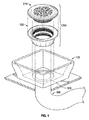
FIG. 1 is an exploded view of a lavatory including an adjustable drain assembly, according to an exemplary embodiment. -
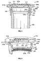
FIG. 2 is a perspective view of the adjustable drain assembly ofFIG. 1 , according to an exemplary embodiment. -
FIG. 3 is a cross-section view taken alongline 3 inFIG. 2 , according to an exemplary embodiment. -
FIG. 4 is a perspective view of an adjustable drain assembly, according to an exemplary embodiment. -
FIG. 5 is a perspective view of a receptor for the adjustable drain assembly ofFIG. 2 , according to an exemplary embodiment -
FIG. 6 is a perspective view of a cover for the adjustable drain assembly ofFIG. 2 , according to an exemplary embodiment. -
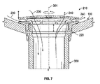
FIG. 7 is a cross-section view of a lavatory system including an adjustable drain assembly, according to an exemplary embodiment. - Referring generally to the FIGURES, disclosed herein are lavatory drains that are selectively adjustable such that a single drain can be used across multiple lavatories, such as lavatories without vent holes (i.e., ventless lavatories). The lavatory drain is adjustable to vary the amount of fluid flowing between the lavatory and a drain pipe such that the drain can adapt to the specific venting and draining requirements of a particular lavatory. In this way, the adjustable drain can prevent air from being trapped in the drain pipe and water from subsequently overflowing from the lavatory. This adjustable aspect also permits the drain to be adaptable for use in a wide variety of lavatories having different flow dynamics and different faucet configurations. Additionally, the adjustable drain allows for significant variations in the design (e.g., shape, size, etc.) of the drain cover and the drain openings to provide for aesthetic variations of the lavatory.
- According to an exemplary embodiment, the lavatory includes a drain assembly having a cover and a receptor. The receptor is configured to couple the lavatory to a drain pipe and the cover is removably coupled to the receptor. The cover includes at least one opening located in an upper surface of the cover defining a first flow path for directing a flow of fluid (e.g., water, air, etc.) between the lavatory and the drain pipe. The cover also includes a plurality of circumferential openings arranged along a peripheral surface of the cover. The cover is disposed above the receptor such that there is a circumferential gap between the receptor and the cover. The circumferential gap and the circumferential openings collectively define a second flow path for directing a flow of fluid to/from the lavatory. The cover is selectively adjustable relative to the receptor to vary the size of the circumferential gap between the cover and the receptor, to thereby increase or decrease an amount of fluid flowing through the second flow path.
- In this manner, the drain assembly can be selectively adjusted to vary the amount of venting/draining of the lavatory to thereby prevent air from being trapped in the drain pipe and water from subsequently overflowing from the lavatory. This adjustable aspect permits the drain assembly to be adaptable for use in a wide variety of lavatories having different flow dynamics and different faucet configurations. For example, the adjustable drain assembly can be used in lavatories having a water discharge stream that is directed toward the top of the cover or in lavatories having a water stream that is discharged along the wall of the lavatory. Furthermore, the configuration of the drain cover and the opening in the drain cover defining the first flow path are not dictated by the venting or draining requirements of the lavatory. Thus, the drain cover can have numerous different design configurations to allow for significant variations in the overall aesthetics of the lavatory. For example, the size of the openings in the drain cover can be sufficiently small to prevent unintended items (e.g., jewelry, personal effects, etc.) from entering the drain and still accommodate the flow of both air and water through the drain, thereby increasing functionality and aesthetic freedom.
- Referring to
FIG. 1 , alavatory 100 including anadjustable drain assembly 200 is shown, according to an exemplary embodiment. As shown inFIG. 1 , thelavatory 100 is a bathroom sink without a vent hole (i.e., a ventless sink). However, in other exemplary embodiments, thelavatory 100 can be another type of vessel or basin, such as a kitchen sink, a utility sink, a tub, or the other similar type of vessel for receiving a fluid. Thelavatory 100 is shown coupled to a fixed structural member, such as a countertop (e.g., a bathroom countertop, a table top, etc.). According to other exemplary embodiments, thelavatory 100 may be coupled to a fixed portion of a building, such as a wall, a floor, or another type of structural member suitable for supporting thelavatory 100. - As shown in
FIG. 1 , thelavatory 100 is in fluidic communication with adrain pipe 300 disposed below thelavatory 100. Thedrain pipe 300 includes a free end positioned within adrain opening 103 of thelavatory 100. Thedrain pipe 300 is configured to direct a flow of fluid (e.g., water, air, etc.) from thelavatory 100 to a sewage or drainage system. Thedrain pipe 300 is also configured to direct a flow of air from thedrain pipe 300 to ambient through the opening of thedrain pipe 300 for venting. For example, a volume of air that is trapped within thedrain pipe 300 can be directed through the opening of thedrain pipe 300 and thedrain opening 103 to the area surrounding thelavatory 100. - An
adjustable drain assembly 200 is configured to couple thelavatory 100 to thedrain pipe 300. Theadjustable drain assembly 200 is also configured to control the draining of thelavatory 100 and to control the venting of thedrain pipe 300. According to the exemplary embodiment ofFIG. 1 , thedrain assembly 200 includes acover 210 and areceptor 220. Thereceptor 220 is configured to couple thelavatory 100 to the drain pipe 300 (seeFIG. 2 ). Thecover 210 is adjustably coupled to thereceptor 220, as shown inFIG. 2 . When thecover 210 is coupled to thereceptor 220, the opening of thedrain pipe 300 and the receptor are concealed from view within thelavatory 100. In this way, thecover 210 appears seamless in the basin of thelavatory 100 to a user looking into the lavatory. - Referring to
FIG. 3 , thedrain assembly 200 is shown coupled to thedrain pipe 300, according to an exemplary embodiment. As shown inFIGS. 3 and5 , thereceptor 220 has a generally hollow cylindrical shape. Thereceptor 220 includes alower end 223 and anupper end 225. Thereceptor 220 is coupled to thedrain pipe 300 at thelower end 223. Thelower end 223 includes a threaded engagement surface engaged with corresponding threads disposed on an outer surface of thedrain pipe 300. According to other exemplary embodiments, thelower end 223 is press-fit onto the drain pipe 300 (see, for example,FIG. 4 ). Thereceptor 220 further includes aninner flange 227. Theinner flange 227 includes anupper engagement surface 227a and alower engagement surface 227b. Thereceptor 220 is coupled to thedrain pipe 300 such that thelower engagement surface 227b contacts at least a portion of thedrain pipe 300. In this way, theinner flange 227 acts as a stop for regulating the position of thereceptor 220 relative to thedrain pipe 300. - As shown in
FIGS. 3 and5 , thereceptor 220 includes anouter flange 229 disposed at theupper end 225. Theouter flange 229 includes anupper surface 229a and alower surface 229b. Thelower surface 229b is configured to contact a surface of thelavatory 100 when thereceptor 220 couples thelavatory 100 to thedrain pipe 300. In effect, theouter flange 229 sandwiches thelavatory 100 to thedrain pipe 300 forming a multi-layered structure with a portion of the lavatory disposed between thereceptor 220 and the drain pipe 300 (shown inFIGS. 2 and7 ). Theupper end 225 of thereceptor 220 includes a threaded engagement surface configured to receive a portion of thecover 210. - According to various exemplary embodiments, the
receptor 220 is made from a rigid or semi-rigid material, such as aluminum, brass, plastic, or other material suitable for the particular application of thereceptor 220. Thereceptor 220 can be machined or formed by various molding techniques (e.g., injection molding, etc.). - Still referring to
FIG. 3 , thecover 210 is adjustably coupled to thereceptor 220. Thecover 210 includes abody 213 and asleeve 215. Thebody 213 is connected to thesleeve 215 by a plurality oftransition elements 217. Each of thetransition elements 217 are arranged concentrically relative to thesleeve 215. Thetransition elements 217, thebody 213 and thesleeve 215 collectively define a plurality of circumferential openings surrounding a portion of thecover 210. Thesleeve 215 includes an outer engagement surface threadably engaged with the upper engagement surface of thereceptor 220. Thecover 210 is selectively adjustable relative to thereceptor 220 via the threaded engagement between thesleeve 215 and the upper engagement surface 225a. - According to an exemplary embodiment shown in
FIG. 4 , thesleeve 215 is press-fit relative to the upper engagement surface of theupper end 225. In the embodiment shown inFIG. 4 , theupper end 225 does not include any threads. Instead, theupper end 225 includes a generally flat engagement surface in contact with thesleeve 215 such that there is an interference fit between thesleeve 215 and theupper end 225 of thereceptor 220. In addition, theupper engagement surface 227a of theinner flange 227 tapers inward from theupper end 225 toward the center of thereceptor 220. - According to various exemplary embodiments, the
cover 210 is made from a rigid or semi-rigid material, such as aluminum, brass, plastic, or other materials or combinations of materials suitable for the particular application of thecover 210. Thecover 210 can be machined or formed by various molding techniques (e.g., injection molding, etc.). Thecover 210 can include various surface treatments or combinations of surface treatments, such as plating, different textures, paints/coatings, and the like. - Referring to
FIGS. 3 and6 , thebody 213 of thecover 210 includes atop surface 213a and abottom surface 213b. Thetop surface 213a includes a drain opening design 211 (shown inFIG. 5 ) including at least one drain opening defining a first flow path for fluid to flow to/from thelavatory 100. Thecover 210 is shown coupled to thereceptor 220 such that a bottom edge of thesleeve 215 contacts theupper engagement surface 227a of theinner flange 227. In effect, theinner flange 227 acts as a stop for regulating the position of thecover 210 relative to thereceptor 220 when thecover 210 is adjustably coupled to thereceptor 220. According to an exemplary embodiment, theinner flange 227 of the receptor is positioned within thereceptor 220 such that when thecover 210 is in contact withinner flange 227, there is a circumferential gap between thebody 213 and theouter flange 229. More specifically, there is a circumferential gap formed between thebottom surface 213a of thebody 213 and theupper surface 229a of theouter flange 229. According to other exemplary embodiments, theinner flange 227 may be located at a different position within thereceptor 220 such that thebody 213 is in contact with theouter flange 229 when thecover 210 engages theinner flange 227. - The circumferential gap between the
body 213 and theouter flange 229, and the circumferential openings of thecover 210, collectively define the second flow path of thedrain assembly 200. The second flow path can vary in size by selectively adjusting thecover 210 relative to thereceptor 220, the details of which are discussed below. The opening in thebody 213 defining the first flow path is fixed and is independent of the second flow path. In this way, thebody 213 can have numerous design configurations. For example, referring toFIG. 5 , thebody 213 includes a patterneddrain opening design 211, according to an exemplary embodiment. Thedrain opening design 211 includes a plurality of drain openings. According to other exemplary embodiments, thedrain opening design 211 includes only one drain opening. In various exemplary embodiments, the size and the shape of the drain openings in thedesign 211 can vary significantly because the venting and draining requirements of thelavatory 100 are met by varying/adjusting the size of the second flow path. The shape of theouter surface 213a of thebody 213 can also vary significantly depending on the particular application of thecover 210. - For example, in the embodiment shown in
FIGS. 2-4 and6 , theouter surface 213a of thebody 213 has a generally convex shape. According to another exemplary embodiment (not shown), theouter surface 213a has a generally planar shape. In other exemplary embodiments (not shown), theouter surface 213a has a generally concave shape. In the embodiment shown inFIGS. 2-3 and5-6 , theouter surface 213a is shaped such that when thecover 210 is coupled to thereceptor 220 in thelavatory 100, thecover 210 has a seamless appearance with the lavatory. That is, thecover 210 has a size (e.g., outer diameter, etc.) sufficient to conceal thereceptor 220 from the view of a user looking into thelavatory 100. This configuration is advantageous because it provides for better aesthetics of thelavatory 100. - Referring to
FIGS. 3 and7 , thecover 210 is adjustable relative to thereceptor 220 to vary the size of the circumferential gap between thebody 213 and theouter flange 229. Adjusting the size of the circumferential gap is desirable because a user can selectively increase or decrease the amount of fluid flowing to or from thelavatory 100 depending on the particular venting or draining requirements of the lavatory. According to an exemplary embodiment, the circumferential gap can be adjusted between about .100 inch and about .170 inch. According to other exemplary embodiments, the circumferential gap can be adjusted between about .100 inch and about .250 inch. - For example, if a user or installer would like to increase the venting/draining capabilities of the
lavatory 100, the user or installer can simply rotate thecover 210 about apivot axis 301 in a counter-clockwise fashion (or a clockwise fashion depending on the configuration of the threaded engagement surfaces) such that the relative distance between thebottom surface 213a of thebody 213 and theupper surface 229a of theouter flange 229 increases (i.e., the circumferential gap). This in turn increases the size of the second flow path to allow for more fluid to flow between thelavatory 100 and thedrain pipe 300. Likewise, if a user or installer wishes to decrease the venting/draining capabilities of the lavatory, the user or installer can rotate thecover 210 about thepivot axis 301 in a direction opposite to the direction for increasing the size of the second flow path. - According to the exemplary embodiment of
FIG. 4 , the relative distance between thebottom surface 213a and theupper surface 229a is selectively adjusted by inserting a spacer between thesleeve 215 and theupper end 225 of thereceptor 220. Depending on the desired amount of adjustment, a user or installer can select a spacer having a size corresponding to the amount of adjustment. For example, if a user or installer determines that the size (e.g., height, etc.) of the second flow path needs to be increased by 1/32 inch, the user or installer can select a spacer having a size of 1/32 inch. The spacer can be inserted into theupper end 225 against a portion of the upper engagement surface. Thecover 210 can then be coupled (e.g., press fit, etc.) to theupper end 225 with a portion of thecover 210 in contact with the spacer to regulate the relative distance between thecover 210 and thereceptor 220. - According to the exemplary embodiment of
FIG. 7 , a flow ofwater 230 or other similar type of fluid is permitted to pass through at least a portion of the second flow path (i.e., the circumferential gap and the circumferential openings) to thedrain pipe 300 to allow for draining of thelavatory 100. Anair flow 240 that is present or trapped in thedrain pipe 300 is permitted to pass up through thedrain pipe 300 through at least a portion of the first flow path and at least a portion of the second flow path to ambient, to allow for venting of thedrain pipe 300. By selectively adjusting the relative size of the second flow path, a user or installer can tailor the drain assembly to increase or decrease the amount of fluid flowing between thelavatory 100 and thedrain pipe 300, depending on the specific draining/venting requirements of the lavatory. - An embodiment provides an adjustable lavatory drain assembly, comprising:
- a receptor having a lower end and an upper end, the upper end of the receptor including an outer flange; and
- a cover removably coupled to the upper end of the receptor, wherein the cover comprises:
- a body including an opening defining a first flow path; and
- a sleeve extending from a bottom surface of the body;
- wherein the cover is selectively adjustable relative to the receptor to increase or decrease the circumferential gap;
- wherein the circumferential gap defines part of a second flow path.
- It may be that the cover includes a plurality of transition elements connecting the body and the sleeve; wherein the plurality of transition elements are arranged to define a plurality of circumferential openings between the body and the sleeve; wherein the plurality of circumferential openings and the circumferential gap collectively define the second flow path.
- It may be that the receptor includes an inner flange disposed between the lower end and the upper end; wherein the inner flange includes an upper engagement surface and a lower engagement surface.
- It may be that the sleeve is configured to contact the upper engagement surface of the inner flange when the cover is installed in the receptor; and wherein the lower engagement surface is configured to contact a portion of a drain pipe when the receptor is coupled to the drain pipe.
- It may be that the sleeve is threadably coupled to the upper end of the receptor.
- It may be that the sleeve is press-fit in the upper end of the receptor.
- It may be that the assembly further comprises a spacer disposed between the sleeve and the lower end of the receptor to set a position of the cover relative to the receptor.
- It may be that the body includes an upper surface having a convex shape.
- It may be that the body includes a plurality of openings defining the first flow path.
- Another embodiment provides an adjustable drain system, comprising:
- a lavatory; and
- a drain assembly configured to couple the lavatory to a drain pipe, the drain assembly comprising:
- a receptor having a lower end and an upper end, the upper end of the receptor including an outer flange; and
- a cover removably coupled to the upper end of the receptor, wherein the cover comprises:
- a body including an opening defining a first flow path; and
- a sleeve extending from a bottom surface of the body;
- wherein the lower end of the receptor is configured to be removably coupled to the drain pipe and a bottom surface of the flange is configured to engage the lavatory;
- wherein the sleeve of the cover is adjustably coupled to the upper end of the receptor forming a circumferential gap between an upper surface of the outer flange and a bottom surface of the body;
- wherein the cover is selectively adjustable relative to the receptor to increase or decrease the circumferential gap;
- wherein the circumferential gap defines part of a second flow path.
- It may be that the first and second flow paths are each configured to: direct a flow of water from the lavatory to the drain pipe, and direct a flow of air from the drain pipe to ambient.
- It may be that the body of the cover conceals the outer flange of the receptor from view.
- It may be that the lavatory is a ventless type lavatory.
- It may be that the cover includes a plurality of transition elements disposed between the body and the sleeve; wherein the plurality of transition elements are arranged to define a plurality of circumferential openings between the body and the sleeve; wherein the plurality of circumferential openings and the circumferential gap collectively define the second flow path.
- It may be that the receptor includes an inner flange disposed between the lower end and the upper end; wherein the inner flange includes an upper engagement surface and a lower engagement surface.
- It may be that the sleeve is configured to contact the upper engagement surface of the inner flange when the cover is installed in the receptor; and wherein the lower engagement surface is configured to contact a portion of the drain pipe when the receptor is coupled to the drain pipe.
- Another embodiment provides an adjustable drain assembly for a lavatory, comprising:
- a receptor configured to removably couple the lavatory to a drain pipe; and
- a cover adjustably coupled to the receptor, the cover including an opening defining a first flow path;
- wherein a portion of the cover and a portion of the receptor cooperatively define a second flow path;
- wherein the cover is configured to move relative to the receptor to selectively increase or decrease a size of the second flow path.
- It may be that the first and second flow paths are each configured to: direct a flow of water from the lavatory to the drain pipe, and direct a flow of air from the drain pipe to ambient.
- It may be that the cover includes a plurality of circumferential openings which define part of the second flow path.
- It may be that the cover is threadably coupled to the receptor; and wherein the cover is configured to rotate relative to the receptor to selectively increase or decrease the size of the second flow path.
- Another embodiment provides a lavatory drain assembly as defined in claim 1. Optional features are the subject of claims 2 to 9.
- Another embodiment provides a lavatory drain system as defined in claim 10. Optional features are the subject of claims 11 to 14.
- Another embodiment provides a lavatory as defined in claim 15.
- As utilized herein, the terms "approximately," "about," "substantially", and similar terms are intended to have a broad meaning in harmony with the common and accepted usage by those of ordinary skill in the art to which the subject matter of this disclosure pertains. It should be understood by those of skill in the art who review this disclosure that these terms are intended to allow a description of certain features described and claimed without restricting the scope of these features to the precise numerical ranges provided. Accordingly, these terms should be interpreted as indicating that insubstantial or inconsequential modifications or alterations of the subject matter described and claimed are considered to be within the scope of the invention as recited in the appended claims.
- It should be noted that the term "exemplary" as used herein to describe various embodiments is intended to indicate that such embodiments are possible examples, representations, and/or illustrations of possible embodiments (and such term is not intended to connote that such embodiments are necessarily extraordinary or superlative examples).
- The terms "coupled," "connected," and the like as used herein mean the joining of two members directly or indirectly to one another. Such joining may be stationary (e.g., permanent) or moveable (e.g., removable or releasable). Such joining may be achieved with the two members or the two members and any additional intermediate members being integrally formed as a single unitary body with one another or with the two members or the two members and any additional intermediate members being attached to one another.
- References herein to the positions of elements (e.g., "top," "bottom," "above," "below," etc.) are merely used to describe the orientation of various elements in the FIGURES. It should be noted that the orientation of various elements may differ according to other exemplary embodiments, and that such variations are intended to be encompassed by the present disclosure.
- It is important to note that the construction and arrangement of the various exemplary embodiments are illustrative only. Although only a few embodiments have been described in detail in this disclosure, those skilled in the art who review this disclosure will readily appreciate that many modifications are possible (e.g., variations in sizes, dimensions, structures, shapes and proportions of the various elements, values of parameters, mounting arrangements, use of materials, colors, orientations, etc.) without materially departing from the novel teachings and advantages of the subject matter described herein. For example, elements shown as integrally formed may be constructed of multiple parts or elements, the position of elements may be reversed or otherwise varied, and the nature or number of discrete elements or positions may be altered or varied. The order or sequence of any process or method steps may be varied or re-sequenced according to alternative embodiments. Other substitutions, modifications, changes and omissions may also be made in the design, operating conditions and arrangement of the various exemplary embodiments without departing from the scope of the present invention.
Claims (15)
- A lavatory drain assembly, comprising:a receptor having a lower end and an upper end, the upper end of the receptor including an outer flange; anda cover removably coupled to the upper end of the receptor, wherein the cover comprises:a body including an opening defining a first flow path, anda sleeve extending from a bottom surface of the body;wherein the cover is adjustably coupled to the upper end of the receptor at the sleeve forming a circumferential gap between an upper surface of the outer flange and a bottom surface of the body;wherein the cover is configured to be selectively adjusted relative to the receptor to increase or decrease the circumferential gap;wherein the circumferential gap defines part of a second flow path.
- The assembly of claim 1, wherein the cover includes a plurality of transition elements connecting the body and the sleeve, wherein the plurality of transition elements are arranged to define a plurality of circumferential openings between the body and the sleeve, and wherein the plurality of circumferential openings and the circumferential gap collectively define the second flow path.
- The assembly of claim 1 or 2, wherein the receptor includes an inner flange disposed between the lower end and the upper end, and wherein the inner flange includes an upper engagement surface and a lower engagement surface.
- The assembly of claim 3, wherein the sleeve is configured to contact the upper engagement surface of the inner flange when the cover is installed in the receptor, and wherein the lower engagement surface is configured to contact a portion of a drain pipe when the receptor is coupled to the drain pipe.
- The assembly of any one of the preceding claims, wherein the sleeve is threadably coupled to the upper end of the receptor.
- The assembly of any one of the preceding claims, wherein the sleeve is press-fit in the upper end of the receptor.
- The assembly of any one of the preceding claims, further comprising a spacer disposed between the sleeve and the lower end of the receptor to set a position of the cover relative to the receptor.
- The assembly of any one of the preceding claims, wherein the body includes an upper surface having a convex shape.
- The assembly of any one of the preceding claims, wherein the body includes a plurality of openings defining the first flow path.
- A lavatory drain system comprising:a lavatory; andthe lavatory drain assembly according to any one of the preceding claims configured to couple the lavatory to a drain pipe;wherein the lower end of the receptor is configured to be removably coupled to the drain pipe and the bottom surface of the flange is configured to engage a surface of the lavatory.
- The system of claim 10, wherein the first and second flow paths are each configured to:direct a flow of water from the lavatory to the drain pipe, anddirect a flow of air from the drain pipe to ambient.
- The system of claim 10 or 11, wherein the body of the cover conceals the outer flange of the receptor from view, and wherein the lavatory is a ventless type lavatory.
- The system of any one of claims 10-13, wherein the cover includes a plurality of transition elements disposed between the body and the sleeve, wherein the plurality of transition elements are arranged to define a plurality of circumferential openings between the body and the sleeve, and wherein the plurality of circumferential openings and the circumferential gap collectively define the second flow path.
- The system of any one of claims 10-14, wherein the cover is threadably coupled to the receptor, and wherein the cover is configured to be rotated relative to the receptor to selectively increase or decrease the size of the second flow path.
- A lavatory comprising the lavatory drain assembly according to any one of claims 1-9.
Applications Claiming Priority (1)
| Application Number | Priority Date | Filing Date | Title |
|---|---|---|---|
| US14/531,262 US9657469B2 (en) | 2014-11-03 | 2014-11-03 | Lavatory drain |
Publications (2)
| Publication Number | Publication Date |
|---|---|
| EP3015611A1 true EP3015611A1 (en) | 2016-05-04 |
| EP3015611B1 EP3015611B1 (en) | 2020-11-25 |
Family
ID=54366043
Family Applications (1)
| Application Number | Title | Priority Date | Filing Date |
|---|---|---|---|
| EP15192465.1A Not-in-force EP3015611B1 (en) | 2014-11-03 | 2015-10-30 | Lavatory drain |
Country Status (3)
| Country | Link |
|---|---|
| US (2) | US9657469B2 (en) |
| EP (1) | EP3015611B1 (en) |
| CN (1) | CN105569136B (en) |
Cited By (1)
| Publication number | Priority date | Publication date | Assignee | Title |
|---|---|---|---|---|
| CN107401199A (en) * | 2017-08-20 | 2017-11-28 | 曹学虎 | A kind of anti-blocking outlet device of easy to clean |
Families Citing this family (10)
| Publication number | Priority date | Publication date | Assignee | Title |
|---|---|---|---|---|
| CA2845558C (en) | 2013-03-13 | 2021-02-09 | Wcm Industries, Inc. | Strainer with improved flow |
| US9657469B2 (en) * | 2014-11-03 | 2017-05-23 | Kohler Co. | Lavatory drain |
| US9743653B2 (en) * | 2015-11-06 | 2017-08-29 | Gem Products, Inc. | Adjustable drain |
| USD886957S1 (en) * | 2017-12-07 | 2020-06-09 | As America, Inc. | Drain cover |
| USD884838S1 (en) | 2018-02-13 | 2020-05-19 | Wcm Industries, Inc. | Strainer |
| CN113006208B (en) * | 2019-12-18 | 2022-12-13 | 科勒公司 | Drain assembly and method of installing the drain assembly to a lavatory |
| CN116782806A (en) * | 2021-01-22 | 2023-09-19 | As 美国股份有限公司 | Drain cover assembly |
| US12227932B2 (en) * | 2021-09-15 | 2025-02-18 | Vendura Industries, LLC | Ligature mitigation drain |
| US11946241B2 (en) | 2022-02-04 | 2024-04-02 | Oatey Co. | Drain assemblies, and related kits and methods |
| US12371892B2 (en) | 2022-03-31 | 2025-07-29 | Oatey Co. | Drain assemblies, and related kits and methods |
Citations (4)
| Publication number | Priority date | Publication date | Assignee | Title |
|---|---|---|---|---|
| WO2006030180A1 (en) * | 2004-09-17 | 2006-03-23 | Dlp Limited | A waste water outlet unit |
| WO2008009874A1 (en) * | 2006-07-15 | 2008-01-24 | Dlp Limited | Height-adjustable shower waste |
| DE202010007534U1 (en) * | 2010-06-02 | 2010-09-02 | Wedi, Stephan | Drainage process for installation in a floor opening of a shower place |
| US20140000022A1 (en) * | 2012-06-27 | 2014-01-02 | Christopher Adam McLeod | Thread-in drain for lavatories. |
Family Cites Families (10)
| Publication number | Priority date | Publication date | Assignee | Title |
|---|---|---|---|---|
| US2143499A (en) | 1937-12-03 | 1939-01-10 | Edward L Siegmann | Drain plug |
| US3742525A (en) | 1971-06-08 | 1973-07-03 | American Brass & Alu | Drain fitting |
| US4146939A (en) | 1977-12-02 | 1979-04-03 | Izzi Lewis B | Drain fitting for pre-formed or pre-assembled showers, etc. |
| US5724684A (en) | 1996-11-06 | 1998-03-10 | Paar; Peter Fedorvich | Raised strainer |
| US6249920B1 (en) | 1998-05-07 | 2001-06-26 | Mcguire Manufacturing Co., Inc. | Grid drain |
| US6381775B1 (en) * | 2000-06-06 | 2002-05-07 | C&D Innovations, L.C. | Adjustable floor drain apparatus |
| GB0311036D0 (en) * | 2003-05-14 | 2003-06-18 | Mcalpine & Co Ltd | Strainer plug waste |
| CN201704749U (en) * | 2010-05-28 | 2011-01-12 | 本溪钢铁(集团)建设有限责任公司 | Plug for intercepting litters |
| US20140165276A1 (en) * | 2012-12-19 | 2014-06-19 | Yu-Ching Huang | Dropping head for wash basin or bathtub |
| US9657469B2 (en) * | 2014-11-03 | 2017-05-23 | Kohler Co. | Lavatory drain |
-
2014
- 2014-11-03 US US14/531,262 patent/US9657469B2/en active Active
-
2015
- 2015-10-30 EP EP15192465.1A patent/EP3015611B1/en not_active Not-in-force
- 2015-11-02 CN CN201510731087.4A patent/CN105569136B/en active Active
-
2017
- 2017-05-16 US US15/596,242 patent/US10060109B2/en active Active
Patent Citations (4)
| Publication number | Priority date | Publication date | Assignee | Title |
|---|---|---|---|---|
| WO2006030180A1 (en) * | 2004-09-17 | 2006-03-23 | Dlp Limited | A waste water outlet unit |
| WO2008009874A1 (en) * | 2006-07-15 | 2008-01-24 | Dlp Limited | Height-adjustable shower waste |
| DE202010007534U1 (en) * | 2010-06-02 | 2010-09-02 | Wedi, Stephan | Drainage process for installation in a floor opening of a shower place |
| US20140000022A1 (en) * | 2012-06-27 | 2014-01-02 | Christopher Adam McLeod | Thread-in drain for lavatories. |
Cited By (1)
| Publication number | Priority date | Publication date | Assignee | Title |
|---|---|---|---|---|
| CN107401199A (en) * | 2017-08-20 | 2017-11-28 | 曹学虎 | A kind of anti-blocking outlet device of easy to clean |
Also Published As
| Publication number | Publication date |
|---|---|
| CN105569136A (en) | 2016-05-11 |
| US9657469B2 (en) | 2017-05-23 |
| CN105569136B (en) | 2018-07-27 |
| US20170254057A1 (en) | 2017-09-07 |
| EP3015611B1 (en) | 2020-11-25 |
| US20160122984A1 (en) | 2016-05-05 |
| US10060109B2 (en) | 2018-08-28 |
Similar Documents
| Publication | Publication Date | Title |
|---|---|---|
| US10060109B2 (en) | Lavatory drain | |
| CN108160368B (en) | A kind of pull-out faucet shower with adjustable flow rate | |
| US20080022455A1 (en) | Waste Outlet | |
| KR20100087100A (en) | Water saving device | |
| CA2924092C (en) | Connecting means for connecting a discharge pipe to a discharge opening | |
| CA2647104C (en) | Spout including a stream straightener | |
| EP3211144B1 (en) | Mixer tap | |
| CA2464407C (en) | Washing platform | |
| CA2979011C (en) | Variable dual flow fitting | |
| US4757841A (en) | Spout with readily serviceable flow control | |
| US6802424B2 (en) | Strainer in shower bath tap valve | |
| JP4237025B2 (en) | Water saving tool and water saving device | |
| US20210340746A1 (en) | Sink Strainer Basket with Odor Prevention Arrangement | |
| CN221778570U (en) | A faucet installation structure | |
| US20170306597A1 (en) | Washer with an adjustable inlet aperture for different water pressure | |
| CN105697813B (en) | Tap with overflow device | |
| US20080174106A1 (en) | Tap | |
| JP2022089348A (en) | Faucet | |
| JP2022091241A (en) | Faucet | |
| CN206928387U (en) | A kind of pulling out leading bullet water water flowing out structure | |
| JP2024091068A (en) | Drainage system | |
| JP5860764B2 (en) | Bathtub used in bathroom washroom | |
| JP2001049709A (en) | Activated water saving and regulating device in water faucet | |
| DE202004007352U1 (en) | Wash basin with tap has basin with integral tap spout having angled water jet outlet holes to reduce spray from water flow | |
| IT201800006397A1 (en) | SINGLE HOLE MIXER TAP WITH DOUBLE CONTROL |
Legal Events
| Date | Code | Title | Description |
|---|---|---|---|
| PUAI | Public reference made under article 153(3) epc to a published international application that has entered the european phase |
Free format text: ORIGINAL CODE: 0009012 |
|
| AK | Designated contracting states |
Kind code of ref document: A1 Designated state(s): AL AT BE BG CH CY CZ DE DK EE ES FI FR GB GR HR HU IE IS IT LI LT LU LV MC MK MT NL NO PL PT RO RS SE SI SK SM TR |
|
| AX | Request for extension of the european patent |
Extension state: BA ME |
|
| STAA | Information on the status of an ep patent application or granted ep patent |
Free format text: STATUS: REQUEST FOR EXAMINATION WAS MADE |
|
| 17P | Request for examination filed |
Effective date: 20161031 |
|
| RBV | Designated contracting states (corrected) |
Designated state(s): AL AT BE BG CH CY CZ DE DK EE ES FI FR GB GR HR HU IE IS IT LI LT LU LV MC MK MT NL NO PL PT RO RS SE SI SK SM TR |
|
| STAA | Information on the status of an ep patent application or granted ep patent |
Free format text: STATUS: EXAMINATION IS IN PROGRESS |
|
| 17Q | First examination report despatched |
Effective date: 20181206 |
|
| GRAP | Despatch of communication of intention to grant a patent |
Free format text: ORIGINAL CODE: EPIDOSNIGR1 |
|
| STAA | Information on the status of an ep patent application or granted ep patent |
Free format text: STATUS: GRANT OF PATENT IS INTENDED |
|
| INTG | Intention to grant announced |
Effective date: 20200602 |
|
| GRAS | Grant fee paid |
Free format text: ORIGINAL CODE: EPIDOSNIGR3 |
|
| GRAA | (expected) grant |
Free format text: ORIGINAL CODE: 0009210 |
|
| STAA | Information on the status of an ep patent application or granted ep patent |
Free format text: STATUS: THE PATENT HAS BEEN GRANTED |
|
| AK | Designated contracting states |
Kind code of ref document: B1 Designated state(s): AL AT BE BG CH CY CZ DE DK EE ES FI FR GB GR HR HU IE IS IT LI LT LU LV MC MK MT NL NO PL PT RO RS SE SI SK SM TR |
|
| REG | Reference to a national code |
Ref country code: GB Ref legal event code: FG4D |
|
| REG | Reference to a national code |
Ref country code: CH Ref legal event code: EP |
|
| REG | Reference to a national code |
Ref country code: AT Ref legal event code: REF Ref document number: 1338457 Country of ref document: AT Kind code of ref document: T Effective date: 20201215 |
|
| REG | Reference to a national code |
Ref country code: DE Ref legal event code: R096 Ref document number: 602015062450 Country of ref document: DE |
|
| REG | Reference to a national code |
Ref country code: IE Ref legal event code: FG4D |
|
| REG | Reference to a national code |
Ref country code: AT Ref legal event code: MK05 Ref document number: 1338457 Country of ref document: AT Kind code of ref document: T Effective date: 20201125 |
|
| REG | Reference to a national code |
Ref country code: NL Ref legal event code: MP Effective date: 20201125 |
|
| PG25 | Lapsed in a contracting state [announced via postgrant information from national office to epo] |
Ref country code: FI Free format text: LAPSE BECAUSE OF FAILURE TO SUBMIT A TRANSLATION OF THE DESCRIPTION OR TO PAY THE FEE WITHIN THE PRESCRIBED TIME-LIMIT Effective date: 20201125 Ref country code: RS Free format text: LAPSE BECAUSE OF FAILURE TO SUBMIT A TRANSLATION OF THE DESCRIPTION OR TO PAY THE FEE WITHIN THE PRESCRIBED TIME-LIMIT Effective date: 20201125 Ref country code: PT Free format text: LAPSE BECAUSE OF FAILURE TO SUBMIT A TRANSLATION OF THE DESCRIPTION OR TO PAY THE FEE WITHIN THE PRESCRIBED TIME-LIMIT Effective date: 20210325 Ref country code: NO Free format text: LAPSE BECAUSE OF FAILURE TO SUBMIT A TRANSLATION OF THE DESCRIPTION OR TO PAY THE FEE WITHIN THE PRESCRIBED TIME-LIMIT Effective date: 20210225 Ref country code: GR Free format text: LAPSE BECAUSE OF FAILURE TO SUBMIT A TRANSLATION OF THE DESCRIPTION OR TO PAY THE FEE WITHIN THE PRESCRIBED TIME-LIMIT Effective date: 20210226 |
|
| PG25 | Lapsed in a contracting state [announced via postgrant information from national office to epo] |
Ref country code: AT Free format text: LAPSE BECAUSE OF FAILURE TO SUBMIT A TRANSLATION OF THE DESCRIPTION OR TO PAY THE FEE WITHIN THE PRESCRIBED TIME-LIMIT Effective date: 20201125 Ref country code: BG Free format text: LAPSE BECAUSE OF FAILURE TO SUBMIT A TRANSLATION OF THE DESCRIPTION OR TO PAY THE FEE WITHIN THE PRESCRIBED TIME-LIMIT Effective date: 20210225 Ref country code: PL Free format text: LAPSE BECAUSE OF FAILURE TO SUBMIT A TRANSLATION OF THE DESCRIPTION OR TO PAY THE FEE WITHIN THE PRESCRIBED TIME-LIMIT Effective date: 20201125 Ref country code: LV Free format text: LAPSE BECAUSE OF FAILURE TO SUBMIT A TRANSLATION OF THE DESCRIPTION OR TO PAY THE FEE WITHIN THE PRESCRIBED TIME-LIMIT Effective date: 20201125 Ref country code: IS Free format text: LAPSE BECAUSE OF FAILURE TO SUBMIT A TRANSLATION OF THE DESCRIPTION OR TO PAY THE FEE WITHIN THE PRESCRIBED TIME-LIMIT Effective date: 20210325 Ref country code: SE Free format text: LAPSE BECAUSE OF FAILURE TO SUBMIT A TRANSLATION OF THE DESCRIPTION OR TO PAY THE FEE WITHIN THE PRESCRIBED TIME-LIMIT Effective date: 20201125 |
|
| REG | Reference to a national code |
Ref country code: LT Ref legal event code: MG9D |
|
| PG25 | Lapsed in a contracting state [announced via postgrant information from national office to epo] |
Ref country code: HR Free format text: LAPSE BECAUSE OF FAILURE TO SUBMIT A TRANSLATION OF THE DESCRIPTION OR TO PAY THE FEE WITHIN THE PRESCRIBED TIME-LIMIT Effective date: 20201125 |
|
| PG25 | Lapsed in a contracting state [announced via postgrant information from national office to epo] |
Ref country code: EE Free format text: LAPSE BECAUSE OF FAILURE TO SUBMIT A TRANSLATION OF THE DESCRIPTION OR TO PAY THE FEE WITHIN THE PRESCRIBED TIME-LIMIT Effective date: 20201125 Ref country code: CZ Free format text: LAPSE BECAUSE OF FAILURE TO SUBMIT A TRANSLATION OF THE DESCRIPTION OR TO PAY THE FEE WITHIN THE PRESCRIBED TIME-LIMIT Effective date: 20201125 Ref country code: SM Free format text: LAPSE BECAUSE OF FAILURE TO SUBMIT A TRANSLATION OF THE DESCRIPTION OR TO PAY THE FEE WITHIN THE PRESCRIBED TIME-LIMIT Effective date: 20201125 Ref country code: SK Free format text: LAPSE BECAUSE OF FAILURE TO SUBMIT A TRANSLATION OF THE DESCRIPTION OR TO PAY THE FEE WITHIN THE PRESCRIBED TIME-LIMIT Effective date: 20201125 Ref country code: RO Free format text: LAPSE BECAUSE OF FAILURE TO SUBMIT A TRANSLATION OF THE DESCRIPTION OR TO PAY THE FEE WITHIN THE PRESCRIBED TIME-LIMIT Effective date: 20201125 Ref country code: LT Free format text: LAPSE BECAUSE OF FAILURE TO SUBMIT A TRANSLATION OF THE DESCRIPTION OR TO PAY THE FEE WITHIN THE PRESCRIBED TIME-LIMIT Effective date: 20201125 |
|
| REG | Reference to a national code |
Ref country code: DE Ref legal event code: R097 Ref document number: 602015062450 Country of ref document: DE |
|
| PG25 | Lapsed in a contracting state [announced via postgrant information from national office to epo] |
Ref country code: DK Free format text: LAPSE BECAUSE OF FAILURE TO SUBMIT A TRANSLATION OF THE DESCRIPTION OR TO PAY THE FEE WITHIN THE PRESCRIBED TIME-LIMIT Effective date: 20201125 |
|
| PLBE | No opposition filed within time limit |
Free format text: ORIGINAL CODE: 0009261 |
|
| STAA | Information on the status of an ep patent application or granted ep patent |
Free format text: STATUS: NO OPPOSITION FILED WITHIN TIME LIMIT |
|
| PG25 | Lapsed in a contracting state [announced via postgrant information from national office to epo] |
Ref country code: NL Free format text: LAPSE BECAUSE OF FAILURE TO SUBMIT A TRANSLATION OF THE DESCRIPTION OR TO PAY THE FEE WITHIN THE PRESCRIBED TIME-LIMIT Effective date: 20201125 Ref country code: AL Free format text: LAPSE BECAUSE OF FAILURE TO SUBMIT A TRANSLATION OF THE DESCRIPTION OR TO PAY THE FEE WITHIN THE PRESCRIBED TIME-LIMIT Effective date: 20201125 Ref country code: IT Free format text: LAPSE BECAUSE OF FAILURE TO SUBMIT A TRANSLATION OF THE DESCRIPTION OR TO PAY THE FEE WITHIN THE PRESCRIBED TIME-LIMIT Effective date: 20201125 |
|
| 26N | No opposition filed |
Effective date: 20210826 |
|
| PG25 | Lapsed in a contracting state [announced via postgrant information from national office to epo] |
Ref country code: ES Free format text: LAPSE BECAUSE OF FAILURE TO SUBMIT A TRANSLATION OF THE DESCRIPTION OR TO PAY THE FEE WITHIN THE PRESCRIBED TIME-LIMIT Effective date: 20201125 Ref country code: SI Free format text: LAPSE BECAUSE OF FAILURE TO SUBMIT A TRANSLATION OF THE DESCRIPTION OR TO PAY THE FEE WITHIN THE PRESCRIBED TIME-LIMIT Effective date: 20201125 |
|
| REG | Reference to a national code |
Ref country code: CH Ref legal event code: PL |
|
| PG25 | Lapsed in a contracting state [announced via postgrant information from national office to epo] |
Ref country code: IS Free format text: LAPSE BECAUSE OF FAILURE TO SUBMIT A TRANSLATION OF THE DESCRIPTION OR TO PAY THE FEE WITHIN THE PRESCRIBED TIME-LIMIT Effective date: 20210325 |
|
| REG | Reference to a national code |
Ref country code: BE Ref legal event code: MM Effective date: 20211031 |
|
| GBPC | Gb: european patent ceased through non-payment of renewal fee |
Effective date: 20211030 |
|
| PG25 | Lapsed in a contracting state [announced via postgrant information from national office to epo] |
Ref country code: MC Free format text: LAPSE BECAUSE OF FAILURE TO SUBMIT A TRANSLATION OF THE DESCRIPTION OR TO PAY THE FEE WITHIN THE PRESCRIBED TIME-LIMIT Effective date: 20201125 |
|
| PG25 | Lapsed in a contracting state [announced via postgrant information from national office to epo] |
Ref country code: LU Free format text: LAPSE BECAUSE OF NON-PAYMENT OF DUE FEES Effective date: 20211030 Ref country code: GB Free format text: LAPSE BECAUSE OF NON-PAYMENT OF DUE FEES Effective date: 20211030 Ref country code: BE Free format text: LAPSE BECAUSE OF NON-PAYMENT OF DUE FEES Effective date: 20211031 |
|
| PG25 | Lapsed in a contracting state [announced via postgrant information from national office to epo] |
Ref country code: LI Free format text: LAPSE BECAUSE OF NON-PAYMENT OF DUE FEES Effective date: 20211031 Ref country code: CH Free format text: LAPSE BECAUSE OF NON-PAYMENT OF DUE FEES Effective date: 20211031 |
|
| PG25 | Lapsed in a contracting state [announced via postgrant information from national office to epo] |
Ref country code: FR Free format text: LAPSE BECAUSE OF NON-PAYMENT OF DUE FEES Effective date: 20211031 |
|
| PG25 | Lapsed in a contracting state [announced via postgrant information from national office to epo] |
Ref country code: IE Free format text: LAPSE BECAUSE OF NON-PAYMENT OF DUE FEES Effective date: 20211030 |
|
| PG25 | Lapsed in a contracting state [announced via postgrant information from national office to epo] |
Ref country code: HU Free format text: LAPSE BECAUSE OF FAILURE TO SUBMIT A TRANSLATION OF THE DESCRIPTION OR TO PAY THE FEE WITHIN THE PRESCRIBED TIME-LIMIT; INVALID AB INITIO Effective date: 20151030 |
|
| PG25 | Lapsed in a contracting state [announced via postgrant information from national office to epo] |
Ref country code: CY Free format text: LAPSE BECAUSE OF FAILURE TO SUBMIT A TRANSLATION OF THE DESCRIPTION OR TO PAY THE FEE WITHIN THE PRESCRIBED TIME-LIMIT Effective date: 20201125 |
|
| P01 | Opt-out of the competence of the unified patent court (upc) registered |
Effective date: 20230707 |
|
| PGFP | Annual fee paid to national office [announced via postgrant information from national office to epo] |
Ref country code: DE Payment date: 20231006 Year of fee payment: 9 |
|
| PG25 | Lapsed in a contracting state [announced via postgrant information from national office to epo] |
Ref country code: MK Free format text: LAPSE BECAUSE OF FAILURE TO SUBMIT A TRANSLATION OF THE DESCRIPTION OR TO PAY THE FEE WITHIN THE PRESCRIBED TIME-LIMIT Effective date: 20201125 |
|
| PG25 | Lapsed in a contracting state [announced via postgrant information from national office to epo] |
Ref country code: TR Free format text: LAPSE BECAUSE OF FAILURE TO SUBMIT A TRANSLATION OF THE DESCRIPTION OR TO PAY THE FEE WITHIN THE PRESCRIBED TIME-LIMIT Effective date: 20201125 |
|
| PG25 | Lapsed in a contracting state [announced via postgrant information from national office to epo] |
Ref country code: MT Free format text: LAPSE BECAUSE OF FAILURE TO SUBMIT A TRANSLATION OF THE DESCRIPTION OR TO PAY THE FEE WITHIN THE PRESCRIBED TIME-LIMIT Effective date: 20201125 |
|
| REG | Reference to a national code |
Ref country code: DE Ref legal event code: R119 Ref document number: 602015062450 Country of ref document: DE |
|
| PG25 | Lapsed in a contracting state [announced via postgrant information from national office to epo] |
Ref country code: DE Free format text: LAPSE BECAUSE OF NON-PAYMENT OF DUE FEES Effective date: 20250501 |