EP3015608A1 - Hydraulic pressure control device for construction machinery - Google Patents
Hydraulic pressure control device for construction machinery Download PDFInfo
- Publication number
- EP3015608A1 EP3015608A1 EP13887856.6A EP13887856A EP3015608A1 EP 3015608 A1 EP3015608 A1 EP 3015608A1 EP 13887856 A EP13887856 A EP 13887856A EP 3015608 A1 EP3015608 A1 EP 3015608A1
- Authority
- EP
- European Patent Office
- Prior art keywords
- control valve
- brake
- hydraulic
- swing motor
- hydraulic pressure
- Prior art date
- Legal status (The legal status is an assumption and is not a legal conclusion. Google has not performed a legal analysis and makes no representation as to the accuracy of the status listed.)
- Withdrawn
Links
- 238000010276 construction Methods 0.000 title claims abstract description 36
- 239000012530 fluid Substances 0.000 claims description 24
- 230000004044 response Effects 0.000 description 10
- 238000010586 diagram Methods 0.000 description 5
- 230000007423 decrease Effects 0.000 description 2
- 230000006872 improvement Effects 0.000 description 2
- 238000000034 method Methods 0.000 description 2
- 230000008569 process Effects 0.000 description 2
- 230000009467 reduction Effects 0.000 description 2
- 230000008859 change Effects 0.000 description 1
- 230000000694 effects Effects 0.000 description 1
- 230000004048 modification Effects 0.000 description 1
- 238000012986 modification Methods 0.000 description 1
- 230000007935 neutral effect Effects 0.000 description 1
Images


Classifications
-
- E—FIXED CONSTRUCTIONS
- E02—HYDRAULIC ENGINEERING; FOUNDATIONS; SOIL SHIFTING
- E02F—DREDGING; SOIL-SHIFTING
- E02F9/00—Component parts of dredgers or soil-shifting machines, not restricted to one of the kinds covered by groups E02F3/00 - E02F7/00
- E02F9/08—Superstructures; Supports for superstructures
- E02F9/10—Supports for movable superstructures mounted on travelling or walking gears or on other superstructures
- E02F9/12—Slewing or traversing gears
- E02F9/121—Turntables, i.e. structure rotatable about 360°
- E02F9/128—Braking systems
-
- F—MECHANICAL ENGINEERING; LIGHTING; HEATING; WEAPONS; BLASTING
- F15—FLUID-PRESSURE ACTUATORS; HYDRAULICS OR PNEUMATICS IN GENERAL
- F15B—SYSTEMS ACTING BY MEANS OF FLUIDS IN GENERAL; FLUID-PRESSURE ACTUATORS, e.g. SERVOMOTORS; DETAILS OF FLUID-PRESSURE SYSTEMS, NOT OTHERWISE PROVIDED FOR
- F15B15/00—Fluid-actuated devices for displacing a member from one position to another; Gearing associated therewith
- F15B15/08—Characterised by the construction of the motor unit
- F15B15/14—Characterised by the construction of the motor unit of the straight-cylinder type
- F15B15/149—Fluid interconnections, e.g. fluid connectors, passages
-
- B—PERFORMING OPERATIONS; TRANSPORTING
- B60—VEHICLES IN GENERAL
- B60T—VEHICLE BRAKE CONTROL SYSTEMS OR PARTS THEREOF; BRAKE CONTROL SYSTEMS OR PARTS THEREOF, IN GENERAL; ARRANGEMENT OF BRAKING ELEMENTS ON VEHICLES IN GENERAL; PORTABLE DEVICES FOR PREVENTING UNWANTED MOVEMENT OF VEHICLES; VEHICLE MODIFICATIONS TO FACILITATE COOLING OF BRAKES
- B60T13/00—Transmitting braking action from initiating means to ultimate brake actuator with power assistance or drive; Brake systems incorporating such transmitting means, e.g. air-pressure brake systems
- B60T13/10—Transmitting braking action from initiating means to ultimate brake actuator with power assistance or drive; Brake systems incorporating such transmitting means, e.g. air-pressure brake systems with fluid assistance, drive, or release
- B60T13/12—Transmitting braking action from initiating means to ultimate brake actuator with power assistance or drive; Brake systems incorporating such transmitting means, e.g. air-pressure brake systems with fluid assistance, drive, or release the fluid being liquid
- B60T13/22—Brakes applied by springs or weights and released hydraulically
-
- B—PERFORMING OPERATIONS; TRANSPORTING
- B60—VEHICLES IN GENERAL
- B60T—VEHICLE BRAKE CONTROL SYSTEMS OR PARTS THEREOF; BRAKE CONTROL SYSTEMS OR PARTS THEREOF, IN GENERAL; ARRANGEMENT OF BRAKING ELEMENTS ON VEHICLES IN GENERAL; PORTABLE DEVICES FOR PREVENTING UNWANTED MOVEMENT OF VEHICLES; VEHICLE MODIFICATIONS TO FACILITATE COOLING OF BRAKES
- B60T13/00—Transmitting braking action from initiating means to ultimate brake actuator with power assistance or drive; Brake systems incorporating such transmitting means, e.g. air-pressure brake systems
- B60T13/10—Transmitting braking action from initiating means to ultimate brake actuator with power assistance or drive; Brake systems incorporating such transmitting means, e.g. air-pressure brake systems with fluid assistance, drive, or release
- B60T13/66—Electrical control in fluid-pressure brake systems
- B60T13/68—Electrical control in fluid-pressure brake systems by electrically-controlled valves
- B60T13/686—Electrical control in fluid-pressure brake systems by electrically-controlled valves in hydraulic systems or parts thereof
-
- E—FIXED CONSTRUCTIONS
- E02—HYDRAULIC ENGINEERING; FOUNDATIONS; SOIL SHIFTING
- E02F—DREDGING; SOIL-SHIFTING
- E02F9/00—Component parts of dredgers or soil-shifting machines, not restricted to one of the kinds covered by groups E02F3/00 - E02F7/00
- E02F9/20—Drives; Control devices
- E02F9/2058—Electric or electro-mechanical or mechanical control devices of vehicle sub-units
- E02F9/2095—Control of electric, electro-mechanical or mechanical equipment not otherwise provided for, e.g. ventilators, electro-driven fans
-
- E—FIXED CONSTRUCTIONS
- E02—HYDRAULIC ENGINEERING; FOUNDATIONS; SOIL SHIFTING
- E02F—DREDGING; SOIL-SHIFTING
- E02F9/00—Component parts of dredgers or soil-shifting machines, not restricted to one of the kinds covered by groups E02F3/00 - E02F7/00
- E02F9/20—Drives; Control devices
- E02F9/22—Hydraulic or pneumatic drives
- E02F9/2217—Hydraulic or pneumatic drives with energy recovery arrangements, e.g. using accumulators, flywheels
-
- E—FIXED CONSTRUCTIONS
- E02—HYDRAULIC ENGINEERING; FOUNDATIONS; SOIL SHIFTING
- E02F—DREDGING; SOIL-SHIFTING
- E02F9/00—Component parts of dredgers or soil-shifting machines, not restricted to one of the kinds covered by groups E02F3/00 - E02F7/00
- E02F9/20—Drives; Control devices
- E02F9/22—Hydraulic or pneumatic drives
- E02F9/2278—Hydraulic circuits
- E02F9/2285—Pilot-operated systems
-
- F—MECHANICAL ENGINEERING; LIGHTING; HEATING; WEAPONS; BLASTING
- F15—FLUID-PRESSURE ACTUATORS; HYDRAULICS OR PNEUMATICS IN GENERAL
- F15B—SYSTEMS ACTING BY MEANS OF FLUIDS IN GENERAL; FLUID-PRESSURE ACTUATORS, e.g. SERVOMOTORS; DETAILS OF FLUID-PRESSURE SYSTEMS, NOT OTHERWISE PROVIDED FOR
- F15B13/00—Details of servomotor systems ; Valves for servomotor systems
- F15B13/02—Fluid distribution or supply devices characterised by their adaptation to the control of servomotors
- F15B13/024—Pressure relief valves
-
- F—MECHANICAL ENGINEERING; LIGHTING; HEATING; WEAPONS; BLASTING
- F15—FLUID-PRESSURE ACTUATORS; HYDRAULICS OR PNEUMATICS IN GENERAL
- F15B—SYSTEMS ACTING BY MEANS OF FLUIDS IN GENERAL; FLUID-PRESSURE ACTUATORS, e.g. SERVOMOTORS; DETAILS OF FLUID-PRESSURE SYSTEMS, NOT OTHERWISE PROVIDED FOR
- F15B1/00—Installations or systems with accumulators; Supply reservoir or sump assemblies
- F15B1/02—Installations or systems with accumulators
- F15B1/021—Installations or systems with accumulators used for damping
-
- F—MECHANICAL ENGINEERING; LIGHTING; HEATING; WEAPONS; BLASTING
- F15—FLUID-PRESSURE ACTUATORS; HYDRAULICS OR PNEUMATICS IN GENERAL
- F15B—SYSTEMS ACTING BY MEANS OF FLUIDS IN GENERAL; FLUID-PRESSURE ACTUATORS, e.g. SERVOMOTORS; DETAILS OF FLUID-PRESSURE SYSTEMS, NOT OTHERWISE PROVIDED FOR
- F15B2211/00—Circuits for servomotor systems
- F15B2211/50—Pressure control
- F15B2211/505—Pressure control characterised by the type of pressure control means
- F15B2211/50509—Pressure control characterised by the type of pressure control means the pressure control means controlling a pressure upstream of the pressure control means
- F15B2211/50545—Pressure control characterised by the type of pressure control means the pressure control means controlling a pressure upstream of the pressure control means using braking valves to maintain a back pressure
-
- F—MECHANICAL ENGINEERING; LIGHTING; HEATING; WEAPONS; BLASTING
- F15—FLUID-PRESSURE ACTUATORS; HYDRAULICS OR PNEUMATICS IN GENERAL
- F15B—SYSTEMS ACTING BY MEANS OF FLUIDS IN GENERAL; FLUID-PRESSURE ACTUATORS, e.g. SERVOMOTORS; DETAILS OF FLUID-PRESSURE SYSTEMS, NOT OTHERWISE PROVIDED FOR
- F15B2211/00—Circuits for servomotor systems
- F15B2211/60—Circuit components or control therefor
- F15B2211/635—Circuits providing pilot pressure to pilot pressure-controlled fluid circuit elements
- F15B2211/6355—Circuits providing pilot pressure to pilot pressure-controlled fluid circuit elements having valve means
-
- F—MECHANICAL ENGINEERING; LIGHTING; HEATING; WEAPONS; BLASTING
- F15—FLUID-PRESSURE ACTUATORS; HYDRAULICS OR PNEUMATICS IN GENERAL
- F15B—SYSTEMS ACTING BY MEANS OF FLUIDS IN GENERAL; FLUID-PRESSURE ACTUATORS, e.g. SERVOMOTORS; DETAILS OF FLUID-PRESSURE SYSTEMS, NOT OTHERWISE PROVIDED FOR
- F15B2211/00—Circuits for servomotor systems
- F15B2211/70—Output members, e.g. hydraulic motors or cylinders or control therefor
- F15B2211/715—Output members, e.g. hydraulic motors or cylinders or control therefor having braking means
Definitions
- the present invention relates to a hydraulic control apparatus for a construction machine. More particularly, the present invention relates to such a hydraulic control apparatus for a construction machine, in which hydraulic fluid discharged from a pilot pump is automatically drained to a hydraulic tank without passing through a relief valve in the braking state of a swing motor brake to prevent a load from continuously occurring at the relief valve.
- a construction machine such as an excavator or a wheel loader includes a lower traveling structure and an upper swing structure swingably mounted on the lower traveling structure so that the construction machine can be useful for performing the construction work.
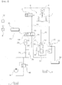
- Fig. 1 is a diagrammatic view schematically showing an excavator which is a construction machine that can perform the construction work while an upper swing structure is swiveled with respect to a lower traveling structure.
- work apparatuses (or attachments) 4 such as a boom, an arm, and a bucket are provided on an upper swing structure 2 so as to be positioned in proximity to an operator's cab.
- the work apparatuses 4 and the upper swing structure 2 are driven by hydraulic fluid discharged from a hydraulic pump.
- the work apparatuses 4 are driven by each actuator including a hydraulic cylinder, and the upper swing structure 2 can be swingably rotated with respect to the lower traveling structure 3 by the rotation of a swing motor 10 during the traveling operation and the construction work.
- the upper swing structure as described above can be stopped in rotation by a swing motor brake device.
- the swing motor brake device is maintained in a braking state at a normal condition, but when the hydraulic pressure from the pilot pump is supplied thereto, the braking state of the swing motor brake device is released.
- the hydraulic fluid from the pilot pump is partially stored in an accumulator and the remaining hydraulic fluid is returned to a hydraulic tank via a relief valve in the braking state of the swing motor brake device or during the operation of the brake. This causes a problem in that a load continuously occurs at the relief valve, thus resulting in a decrease in the energy efficiency.
- a hydraulic circuit is configured such that a hydraulic pressure is used at a traveling speed switching valve, for example, a first or second traveling speed switching valve or a traveling control valve to change the traveling speed in the braking state of the swing motor brake, the load continuously occurs at the relief valve and thus the energy efficiency decreases as described above.
- a traveling speed switching valve for example, a first or second traveling speed switching valve or a traveling control valve to change the traveling speed in the braking state of the swing motor brake
- the present invention has been made to solve the aforementioned problems occurring in the prior art, and it is an object of the present invention to provide a hydraulic control apparatus for a construction machine, in which, hydraulic fluid discharged from a pilot pump is automatically drained to a hydraulic tank without passing through a relief valve in the braking state of a swing motor brake to prevent a load from continuously occurring at the relief valve.
- Another object of the present invention is to provide a hydraulic control apparatus for a construction machine, in which even in the case where there is no manipulation for changing the traveling speed in the braking state of the swing motor brake, hydraulic fluid discharged from a pilot pump is automatically drained to a hydraulic tank without passing through a relief valve to prevent a load from continuously occurring at the relief valve.
- a hydraulic control device for a construction machine including:
- the hydraulic control apparatus for a construction machine in accordance with the present invention may further include an accumulator installed in a flow path formed between the brake control valve and the pilot pump and configured to store the hydraulic fluid that is discharged from the pilot pump.
- the hydraulic control apparatus for a construction machine in accordance with the present invention may further include: a switch installed to be electrically connected to the controller; and a signal pressure control valve installed on a downstream side of the drain control valve and configured to be opened or closed so as to control the pilot hydraulic pressure that passes through the drain control valve depending on a manipulation of the switch.
- the controller may control the brake control valve depending to be opened and closed on a manipulation signal that is applied thereto from a work apparatus manipulation lever.
- a traveling control valve may be installed at a downstream side of the signal pressure control valve in such a manner as to be connected to the signal pressure control valve.
- the traveling control valve may be configured as a first or second traveling speed control valve.
- the hydraulic control apparatus for a construction machine in accordance with the present invention as constructed above has the following advantages.
- the hydraulic fluid discharged from the pilot pump is automatically drained to the hydraulic tank by the drain control valve without passing through the relief valve in the braking state of the swing motor brake so that the reduction in a load of the relief valve and the improvement of the energy efficiency of the hydraulic system can be promoted.
- the drain control valve is operated even in the case where there is no manipulation for changing the traveling speed in the braking state of the swing motor brake so that the load of the relief valve can be significantly reduced.
- the hydraulic fluid discharged from the pilot pump is automatically used as a signal pressure for the control of the traveling control valve without passing through the relief valve so that the energy of a hydraulic system can be efficiently utilized.
- Fig. 2 is a hydraulic circuit diagram showing the brake release control operation of the brake control valve to rotate the swing motor in accordance with a preferred embodiment of the present invention
- Fig. 3 is a hydraulic circuit diagram as shown in Fig. 2 , showing the flow of a hydraulic pressure when a brake control valve is operated to be closed to brake the swing motor at a normal condition.
- Fig. 2 shows a hydraulic circuit diagram for describing the braking operation of the swing motor brake in accordance with a preferred embodiment of the present invention.
- a reference numeral denotes a swing motor brake
- a reference numeral 9 denotes a pilot pump
- a reference numeral 10 denotes a swing motor
- a reference numeral denotes a brake control valve
- a reference numeral 17 denotes a drain control valve
- a reference numeral 20 denotes a signal pressure control valve
- a reference numeral 33 denotes a controller
- a reference numeral 32 denotes a switch
- a reference numeral 40 denotes a relief valve.
- the hydraulic control apparatus for a construction machine 1 in accordance with the present invention is configured such that the release operation of the swing motor brake 5 is performed by a hydraulic pressure discharged from the pilot pump 9 in the construction machine 1 including an excavator, and the hydraulic pressure is drained to a hydraulic tank T by the drain control valve 17 without passing through the relief valve 40 when the brake control valve 11 is shifted to allow the swing motor brake 5 to be released.
- a hydraulic control apparatus for a construction machine in accordance with the present invention includes a pilot pump 9 that is configured to provide a pilot hydraulic pressure, and a swing motor 10 that is configured to swingably rotate an upper swing structure.
- the swing motor 10 is driven by a hydraulic pressure, and can be supplied with the hydraulic pressure from a swing pump (not shown) installed at a known excavator.
- a swing control valve (not shown) that changes a direction of the hydraulic pressure discharged from the swing pump can convert the rotation direction of the swing motor 10.
- the rotation or swing of the upper swing structure 2 is performed in the traveling or construction work.
- the hydraulic control apparatus for a construction machine in accordance with the present invention includes a swing motor brake 5 that is coupled to the swing motor 10 to brake the swing motor 10 at a normal condition and is released to rotate the swing motor 10 when the pilot hydraulic pressure is supplied thereto, and a brake control valve 11 that is installed between the pilot pump 9 and the swing motor brake 5 and is configured to control a direction of the pilot hydraulic pressure or hydraulic fluid discharged from the pilot pump 9 to allow for the braking and release of the swing motor brake 5.
- the brake control valve 11 may include a supply port 12, a return port 13, and a solenoid 14 that is driven in response to an electrical control signal or a command signal.
- the swing motor brake 5 includes a brake cylinder 6 and a multi-disk brake 7.
- a piston of the brake cylinder 6 is elastically supported so that the multi-disk brake 7 is coupled to the swing motor 10 by a frictional force to restrict the rotation of the swing motor 10 in the normal state.
- normal condition is intended to understand a work condition of the construction machine in which the upper swing structure 2 are not required to be rotated.
- the term "normal state” should be construed as including a state in which a swing pump or a swash plate control device for the swing pump is controlled to a neutral position and a state in which there are no a pilot signal pressure or an electrical control signal according to the manipulation of a manipulation lever or a joystick, and a command signal corresponding to the manipulation.
- the hydraulic control apparatus for a construction machine includes: a controller 33 that is configured to receive a command signal for driving the swing motor 10 and apply the received command signal to the brake control valve 11; a relief valve 40 that is installed between the brake control valve 11 and the pilot pump 9 and, if a hydraulic pressure that exceeds a predetermined relief pressure is generated between the brake control valve 11 and the pilot pump 9, is configured to allow the hydraulic pressure to be returned to a hydraulic tank T; and a drain control valve 17 that is installed in parallel with the brake control valve 11 and configured to be opened or closed so that the pilot hydraulic pressure is selectively returned to the hydraulic tank T depending on a state of the brake control valve 11.
- the drain control valve 17 may include an inlet port 18 to which the hydraulic fluid from the pilot pump 9 is introduced, and a solenoid 19 that is driven in response to an electrical control signal or a command signal.
- the drain control valve 17 is closed.
- the brake control valve 11 is shifted to restrict the rotation of the swing motor 10 or allow for the braking of the swing motor brake 5
- the drain control valve 17 is opened so that the hydraulic pressure is drained to the hydraulic tank T without passing through the relief valve 40.
- the hydraulic control apparatus for a construction machine in accordance with the present invention further includes an accumulator 23 that is installed in a supply line 30 formed between the brake control valve 11 and the pilot pump 9 and is configured to store the hydraulic fluid that is discharged from the pilot pump 9.
- a filter 24 may be provided between the pilot pump 9 and the accumulator 23 in consideration of viscosity and performance of the hydraulic fluid on the supply line 20.
- a check valve 25 may be further provided between the pilot pump 9 and the accumulator 23 to prevent the backflow of the hydraulic fluid from the accumulator 23.
- the hydraulic control apparatus for a construction machine in accordance with the present invention further includes a switch 32 that is installed to be electrically connected to the controller 33, and a signal pressure control valve 20 that is installed on a downstream side of the drain control valve 17 and is opened or closed so as to control the pilot hydraulic pressure that passes through the drain control valve 17 depending on a manipulation of the switch 32.
- the signal pressure control valve 20 may include an inlet port 21 for a pilot signal pressure, and a solenoid 22 for a control signal that depends on the manipulation of the switch 32.
- the controller 33 may be configured as an electronic control unit (ECU) or a vehicle electronic control unit (VECU) for the construction machine.
- the controller 33 controls the brake control valve 11 to be opened or closed depending on a manipulation signal that is applied thereto from a swing joystick or a work apparatus manipulation lever 8.
- the controller 33 that processes a predetermined command signal can receive an electrical signal as a manipulation signal from the joystick 8 to swing or rotate the upper swing structure 2, and output a control signal for application to the brake control valve 11 or the drain control valve 17 to open and close the brake control valve 11 or the drain control valve 17 in response to the manipulation signal from the joystick 8.
- the control signal includes an electric solenoid control signal, and can be separately or simultaneously applied to the brake control valve 11 and the drain control valve 17.
- a traveling control valve 34 is installed at a downstream side of the signal pressure control valve 20 in such a manner as to be connected to the signal pressure control valve 20.
- the traveling control valve 34 is configured as a first or second traveling speed control valve.
- the brake control valve 11 is maintained in a closed state so that the swing motor brake 5 brakes the swing motor 10 to restrict the rotation of the swing motor 10 at a normal condition.
- the hydraulic fluid or the pilot hydraulic pressure discharged from the pilot pump 9 can be drained to the hydraulic tank T through the drain control valve 17 without passing through the relief valve 40.
- the hydraulic fluid or the pilot hydraulic pressure discharged from the pilot pump 9 can be drained to the hydraulic tank T through the drain control valve 17 without passing through the relief valve 40.
- the swing motor brake 5 When an operator performs the operation of the work apparatus 4 or the upper swing structure 2, the swing motor brake 5 is released.
- the controller 33 receives an electrical signal according to the manipulation of the joystick as a command signal corresponding to the release of the brake and applies a valve control command signal for the release of the swing motor brake 5 to the brake control valve 11.
- the controller 33 applies a command signal to the brake control valve 11 to cause the brake control valve 11 to be opened.
- the brake control valve 11 When the command signal which is an electrical control signal is applied to the solenoid 14 of the brake control valve 11, the brake control valve 11 is opened by the movement or stroke of the solenoid 14.
- the hydraulic fluid or pilot hydraulic pressure discharged from the pilot pump 9 is supplied to the brake cylinder 6 via the supply line 30, the supply port 20, and a brake hydraulic line 31.
- the drain control valve 17 is maintained in a closed state, and the hydraulic fluid or pilot hydraulic pressure discharged from the pilot pump 9 can be supplied to the brake cylinder 6 without being drained via a drain line 36.
- the rotation direction of the swing motor 10 depends on the control of the direction of the pilot hydraulic pressure by the swing control valve, and thus the swingable rotation of the upper swing structure 2 is performed.
- the swing motor brake 5 is maintained in the braking state to brake the swing motor 10 by the engagement between the swing motor 10 and the brake disk 7.
- the brake control valve 11 is maintained in a closed state in response to the command signal of the controller 33.
- the brake control valve 11 is closed in response to the command signal applied thereto from the controller 33, and the hydraulic fluid or pilot hydraulic pressure discharged from the pilot pump 9 can be filled in the accumulator 24 via the filter 24.
- a hydraulic pressure applied to the supply line 30 between the pilot pump 9 and the brake control valve 11 is introduced into the inlet port 18 of the drain control valve 17 via a parallel flow path 36 connected to the supply line 30.
- a predetermined command signal or control signal from the controller 33 is applied to the solenoid 19 of the drain control valve 17 to drain the hydraulic pressure introduced into the inlet port 18, and thus the drain control valve 17 is opened so that the hydraulic pressure applied from the pilot pump 9 to the supply line 30, is drained to the hydraulic tank T via the drain control valve 17 through the parallel flow path 36 and the inlet port 18 without passing through the relief valve 40.
- a load applied to the relief valve 40 is significantly reduced by a function of controlling the drain flow rate of the drain control valve 17, and the energy efficiency of the hydraulic system is improved.
- the signal pressure control valve 20 is maintained in a closed state.
- the hydraulic fluid or pilot hydraulic pressure discharged from the pilot pump 9 can be supplied as a predetermined pilot signal pressure.
- the drain control valve 17 is closed in response to the predetermined command signal from the controller 33, and thus the hydraulic pressure applied from the pilot pump 9 to the supply line 30 is introduced into the inlet port 21 of the signal pressure control valve 20 through the parallel flow path 36 and a signal pressure line 37.
- the signal pressure control valve 20 is switched to an opened state in response to a manipulation signal from the switch 32.
- the hydraulic pressure from the pilot pump 9, which is introduced into the inlet port 21 through signal pressure line 37, is supplied, as a pilot signal pressure, to the traveling control valve 34.
- the traveling control valve 34 is configured as a first or second traveling speed control valve
- the pilot signal pressure can be supplied as a signal pressure for the shift of a valve spool for changing the traveling speed of the lower traveling structure 3.
- the drain control valve 17 is opened in response to the command signal from the controller 33, and the hydraulic pressure applied from the pilot pump 9 to the supply line 30 is drained to the hydraulic tank T through the drain control valve 17 via the inlet port 18.
- the hydraulic fluid discharged from the pilot pump is automatically drained to the hydraulic tank by the drain control valve without passing through the relief valve in the braking state of the swing motor brake so that the hydraulic control apparatus can be useful for promotion of the reduction in a load of the relief valve and the improvement of the energy efficiency of the hydraulic system.
Landscapes
- Engineering & Computer Science (AREA)
- General Engineering & Computer Science (AREA)
- Mining & Mineral Resources (AREA)
- Civil Engineering (AREA)
- Structural Engineering (AREA)
- Mechanical Engineering (AREA)
- Transportation (AREA)
- Physics & Mathematics (AREA)
- Fluid Mechanics (AREA)
- Operation Control Of Excavators (AREA)
- Fluid-Pressure Circuits (AREA)
Abstract
Description
- The present invention relates to a hydraulic control apparatus for a construction machine. More particularly, the present invention relates to such a hydraulic control apparatus for a construction machine, in which hydraulic fluid discharged from a pilot pump is automatically drained to a hydraulic tank without passing through a relief valve in the braking state of a swing motor brake to prevent a load from continuously occurring at the relief valve.
- In general, a construction machine such as an excavator or a wheel loader includes a lower traveling structure and an upper swing structure swingably mounted on the lower traveling structure so that the construction machine can be useful for performing the construction work.
-
Fig. 1 is a diagrammatic view schematically showing an excavator which is a construction machine that can perform the construction work while an upper swing structure is swiveled with respect to a lower traveling structure. - In a conventional construction machine 1, work apparatuses (or attachments) 4 such as a boom, an arm, and a bucket are provided on an
upper swing structure 2 so as to be positioned in proximity to an operator's cab. Thework apparatuses 4 and theupper swing structure 2 are driven by hydraulic fluid discharged from a hydraulic pump. For example, thework apparatuses 4 are driven by each actuator including a hydraulic cylinder, and theupper swing structure 2 can be swingably rotated with respect to the lower traveling structure 3 by the rotation of aswing motor 10 during the traveling operation and the construction work. - The upper swing structure as described above can be stopped in rotation by a swing motor brake device. The swing motor brake device is maintained in a braking state at a normal condition, but when the hydraulic pressure from the pilot pump is supplied thereto, the braking state of the swing motor brake device is released.
- However, the hydraulic fluid from the pilot pump is partially stored in an accumulator and the remaining hydraulic fluid is returned to a hydraulic tank via a relief valve in the braking state of the swing motor brake device or during the operation of the brake. This causes a problem in that a load continuously occurs at the relief valve, thus resulting in a decrease in the energy efficiency.
- Even in the case where a hydraulic circuit is configured such that a hydraulic pressure is used at a traveling speed switching valve, for example, a first or second traveling speed switching valve or a traveling control valve to change the traveling speed in the braking state of the swing motor brake, the load continuously occurs at the relief valve and thus the energy efficiency decreases as described above.
- Accordingly, the present invention has been made to solve the aforementioned problems occurring in the prior art, and it is an object of the present invention to provide a hydraulic control apparatus for a construction machine, in which, hydraulic fluid discharged from a pilot pump is automatically drained to a hydraulic tank without passing through a relief valve in the braking state of a swing motor brake to prevent a load from continuously occurring at the relief valve.
- Another object of the present invention is to provide a hydraulic control apparatus for a construction machine, in which even in the case where there is no manipulation for changing the traveling speed in the braking state of the swing motor brake, hydraulic fluid discharged from a pilot pump is automatically drained to a hydraulic tank without passing through a relief valve to prevent a load from continuously occurring at the relief valve.
- To achieve the above object, in accordance with an embodiment of the present invention, there is provided a hydraulic control device for a construction machine, including:
- A hydraulic control apparatus for a construction machine comprising:
- a pilot pump configured to provide a pilot hydraulic pressure;
- a swing motor configured to swingably rotate an upper swing structure;
- a swing motor brake coupled to the swing motor to brake the swing motor at a normal condition and configured to be released to rotate the swing motor when the pilot hydraulic pressure is supplied thereto;
- a brake control valve installed between the pilot pump and the swing motor brake and configured to control a direction of the pilot hydraulic pressure to allow for the braking and release of the swing motor brake;
- a controller configured to receive a command signal for driving the swing motor and apply the received command signal to the brake control valve;
- a relief valve installed between the brake control valve and the pilot pump and, if a hydraulic pressure that exceeds a predetermined relief pressure is generated between the brake control valve and the pilot pump, configured to allow the hydraulic pressure to be returned to a hydraulic tank; and
- a drain control valve installed in parallel with the brake control valve and configured to be opened or closed so that the pilot hydraulic pressure is selectively returned to the hydraulic tank depending on a state of the brake control valve,
- wherein if the brake control valve is shifted to rotate the swing motor, the drain control valve is closed, while if the brake control valve is shifted to brake the
swing motor 10, the drain control valve is opened so that the hydraulic pressure is drained to the hydraulic tank without passing through the relief valve.
- The hydraulic control apparatus for a construction machine in accordance with the present invention may further include an accumulator installed in a flow path formed between the brake control valve and the pilot pump and configured to store the hydraulic fluid that is discharged from the pilot pump.
- In addition, the hydraulic control apparatus for a construction machine in accordance with the present invention may further include: a switch installed to be electrically connected to the controller; and a signal pressure control valve installed on a downstream side of the drain control valve and configured to be opened or closed so as to control the pilot hydraulic pressure that passes through the drain control valve depending on a manipulation of the switch.
- In accordance with a preferred embodiment of the present invention, the controller may control the brake control valve depending to be opened and closed on a manipulation signal that is applied thereto from a work apparatus manipulation lever.
- Further, in accordance with a preferred embodiment of the present invention, a traveling control valve may be installed at a downstream side of the signal pressure control valve in such a manner as to be connected to the signal pressure control valve.
- In accordance with a preferred embodiment of the present invention, the traveling control valve may be configured as a first or second traveling speed control valve.
- The hydraulic control apparatus for a construction machine in accordance with the present invention as constructed above has the following advantages.
- The hydraulic fluid discharged from the pilot pump is automatically drained to the hydraulic tank by the drain control valve without passing through the relief valve in the braking state of the swing motor brake so that the reduction in a load of the relief valve and the improvement of the energy efficiency of the hydraulic system can be promoted.
- In addition, the drain control valve is operated even in the case where there is no manipulation for changing the traveling speed in the braking state of the swing motor brake so that the load of the relief valve can be significantly reduced. Besides, in the case where there is a manipulation for changing the traveling speed under the circumstances, the hydraulic fluid discharged from the pilot pump is automatically used as a signal pressure for the control of the traveling control valve without passing through the relief valve so that the energy of a hydraulic system can be efficiently utilized.
- The above objects, other features and advantages of the present invention will become more apparent by describing the preferred embodiments thereof with reference to the accompanying drawings, in which:
-
Fig. 1 is a diagrammatic view schematically showing an excavator which is a construction machine that can perform the construction work while an upper swing structure is swiveled with respect to a lower traveling structure; -
Fig. 2 is a hydraulic circuit diagram showing the brake release control operation of the brake control valve to rotate the swing motor in accordance with a preferred embodiment of the present invention; and -
Fig. 3 is a hydraulic circuit diagram as shown inFig. 2 , showing the flow of a hydraulic pressure when a brake control valve is operated to be closed to brake the swing motor at a normal condition. - Hereinafter, a hydraulic control apparatus for a construction machine in accordance with a preferred embodiment of the present invention will be described in detail with reference to the accompanying drawings. The matters defined in the description, such as the detailed construction and elements, are nothing but specific details provided to assist those of ordinary skill in the art in a comprehensive understanding of the invention, and the present invention is not limited to the embodiments disclosed hereinafter.
- In order to definitely describe the present invention, a portion having no relevant to the description will be omitted, and through the specification, like elements are designated by like reference numerals.
- In the specification and the claims, when a portion includes an element, it is meant to include other elements, but not exclude the other elements unless otherwise specifically stated herein.
- Prior to the following detailed description, the terms or words used in the specification and the claims of the present invention should not be construed as being typical or dictionary meanings, but should be construed as meanings and concepts conforming to the technical spirit of the present invention on the basis of the principle that an inventor can properly define the concepts of the terms in order to describe his or her invention in the best way.
-
Fig. 2 is a hydraulic circuit diagram showing the brake release control operation of the brake control valve to rotate the swing motor in accordance with a preferred embodiment of the present invention, andFig. 3 is a hydraulic circuit diagram as shown inFig. 2 , showing the flow of a hydraulic pressure when a brake control valve is operated to be closed to brake the swing motor at a normal condition. -
Fig. 2 shows a hydraulic circuit diagram for describing the braking operation of the swing motor brake in accordance with a preferred embodiment of the present invention. - Prior to the following detailed description, a reference numeral denotes a swing motor brake, a reference numeral 9 denotes a pilot pump, a
reference numeral 10 denotes a swing motor, a reference numeral denotes a brake control valve, areference numeral 17 denotes a drain control valve, areference numeral 20 denotes a signal pressure control valve, areference numeral 33 denotes a controller, areference numeral 32 denotes aswitch, a
reference numeral 40 denotes a relief valve. - As shown in
Figs. 2 and3 , the hydraulic control apparatus for a construction machine 1 in accordance with the present invention is configured such that the release operation of theswing motor brake 5 is performed by a hydraulic pressure discharged from the pilot pump 9 in the construction machine 1 including an excavator, and the hydraulic pressure is drained to a hydraulic tank T by thedrain control valve 17 without passing through therelief valve 40 when thebrake control valve 11 is shifted to allow theswing motor brake 5 to be released. - More specifically, referring to the drawings, a hydraulic control apparatus for a construction machine in accordance with the present invention includes a pilot pump 9 that is configured to provide a pilot hydraulic pressure, and a
swing motor 10 that is configured to swingably rotate an upper swing structure. - The
swing motor 10 is driven by a hydraulic pressure, and can be supplied with the hydraulic pressure from a swing pump (not shown) installed at a known excavator. In addition, a swing control valve (not shown) that changes a direction of the hydraulic pressure discharged from the swing pump can convert the rotation direction of theswing motor 10. Thus, the rotation or swing of theupper swing structure 2 is performed in the traveling or construction work. - The hydraulic control apparatus for a construction machine in accordance with the present invention includes a
swing motor brake 5 that is coupled to theswing motor 10 to brake theswing motor 10 at a normal condition and is released to rotate theswing motor 10 when the pilot hydraulic pressure is supplied thereto, and abrake control valve 11 that is installed between the pilot pump 9 and theswing motor brake 5 and is configured to control a direction of the pilot hydraulic pressure or hydraulic fluid discharged from the pilot pump 9 to allow for the braking and release of theswing motor brake 5. - The
brake control valve 11 may include asupply port 12, areturn port 13, and asolenoid 14 that is driven in response to an electrical control signal or a command signal. - In addition, the
swing motor brake 5 includes abrake cylinder 6 and a multi-disk brake 7. A piston of thebrake cylinder 6 is elastically supported so that the multi-disk brake 7 is coupled to theswing motor 10 by a frictional force to restrict the rotation of theswing motor 10 in the normal state. - In the description of the present invention, the phrase "normal condition" is intended to understand a work condition of the construction machine in which the
upper swing structure 2 are not required to be rotated. The term "normal state" should be construed as including a state in which a swing pump or a swash plate control device for the swing pump is controlled to a neutral position and a state in which there are no a pilot signal pressure or an electrical control signal according to the manipulation of a manipulation lever or a joystick, and a command signal corresponding to the manipulation. - In the meantime, the hydraulic control apparatus for a construction machine in accordance with the present invention includes: a
controller 33 that is configured to receive a command signal for driving theswing motor 10 and apply the received command signal to thebrake control valve 11; arelief valve 40 that is installed between thebrake control valve 11 and the pilot pump 9 and, if a hydraulic pressure that exceeds a predetermined relief pressure is generated between thebrake control valve 11 and the pilot pump 9, is configured to allow the hydraulic pressure to be returned to a hydraulic tank T; and adrain control valve 17 that is installed in parallel with thebrake control valve 11 and configured to be opened or closed so that the pilot hydraulic pressure is selectively returned to the hydraulic tank T depending on a state of thebrake control valve 11. - Preferably, the
drain control valve 17 may include aninlet port 18 to which the hydraulic fluid from the pilot pump 9 is introduced, and asolenoid 19 that is driven in response to an electrical control signal or a command signal. When thebrake control valve 11 is shifted to rotate theswing motor 10 or allow for the release of theswing motor brake 5, thedrain control valve 17 is closed. On the other hand, when thebrake control valve 11 is shifted to restrict the rotation of theswing motor 10 or allow for the braking of theswing motor brake 5, thedrain control valve 17 is opened so that the hydraulic pressure is drained to the hydraulic tank T without passing through therelief valve 40. - Meanwhile, the hydraulic control apparatus for a construction machine in accordance with the present invention further includes an
accumulator 23 that is installed in asupply line 30 formed between thebrake control valve 11 and the pilot pump 9 and is configured to store the hydraulic fluid that is discharged from the pilot pump 9. - A
filter 24 may be provided between the pilot pump 9 and theaccumulator 23 in consideration of viscosity and performance of the hydraulic fluid on thesupply line 20. In addition, acheck valve 25 may be further provided between the pilot pump 9 and theaccumulator 23 to prevent the backflow of the hydraulic fluid from theaccumulator 23. - The hydraulic control apparatus for a construction machine in accordance with the present invention further includes a
switch 32 that is installed to be electrically connected to thecontroller 33, and a signalpressure control valve 20 that is installed on a downstream side of thedrain control valve 17 and is opened or closed so as to control the pilot hydraulic pressure that passes through thedrain control valve 17 depending on a manipulation of theswitch 32. - The signal
pressure control valve 20 may include aninlet port 21 for a pilot signal pressure, and asolenoid 22 for a control signal that depends on the manipulation of theswitch 32. - The
controller 33 may be configured as an electronic control unit (ECU) or a vehicle electronic control unit (VECU) for the construction machine. Thecontroller 33 controls thebrake control valve 11 to be opened or closed depending on a manipulation signal that is applied thereto from a swing joystick or a workapparatus manipulation lever 8. - Preferably, as described above, the
controller 33 that processes a predetermined command signal can receive an electrical signal as a manipulation signal from thejoystick 8 to swing or rotate theupper swing structure 2, and output a control signal for application to thebrake control valve 11 or thedrain control valve 17 to open and close thebrake control valve 11 or thedrain control valve 17 in response to the manipulation signal from thejoystick 8. - The control signal includes an electric solenoid control signal, and can be separately or simultaneously applied to the
brake control valve 11 and thedrain control valve 17. - In accordance with the present invention, a traveling
control valve 34 is installed at a downstream side of the signalpressure control valve 20 in such a manner as to be connected to the signalpressure control valve 20. Preferably, the travelingcontrol valve 34 is configured as a first or second traveling speed control valve. - Hereinafter, the construction and operating principle of the hydraulic control apparatus for a construction machine in accordance with an embodiment of the present invention will be described with reference to the accompanying drawings.
- Referring to
Fig. 2 , when theswing motor brake 5 is operated to release the braking of theswing motor 10 to cause theupper swing structure 2 to be swiveled, the hydraulic fluid discharged from the pilot pump 9 is supplied to thebrake cylinder 6 of theswing motor brake 5 in response to the opening of thebrake control valve 11. - On the other hand, referring to
Fig. 3 , thebrake control valve 11 is maintained in a closed state so that theswing motor brake 5 brakes theswing motor 10 to restrict the rotation of theswing motor 10 at a normal condition. In this case, the hydraulic fluid or the pilot hydraulic pressure discharged from the pilot pump 9 can be drained to the hydraulic tank T through thedrain control valve 17 without passing through therelief valve 40. - More preferably, in the case where there is no manipulations or signal for allowing for the release of the
swing motor brake 5 or changing the traveling speed, the hydraulic fluid or the pilot hydraulic pressure discharged from the pilot pump 9 can be drained to the hydraulic tank T through thedrain control valve 17 without passing through therelief valve 40. - Specifically, the operating principle of the hydraulic control apparatus during the release of the
swing motor brake 5 will be described - When an operator performs the operation of the
work apparatus 4 or theupper swing structure 2, theswing motor brake 5 is released. For example, when the operator manipulates the manipulation lever or thejoystick 8, thecontroller 33 receives an electrical signal according to the manipulation of the joystick as a command signal corresponding to the release of the brake and applies a valve control command signal for the release of theswing motor brake 5 to thebrake control valve 11. - Specifically, as shown in
Fig. 2 , when thejoystick 8 is manipulated by the operator and thus the command signal according to the manipulation of thejoystick 8 is applied to thecontroller 33, thecontroller 33 applies a command signal to thebrake control valve 11 to cause thebrake control valve 11 to be opened. - When the command signal which is an electrical control signal is applied to the
solenoid 14 of thebrake control valve 11, thebrake control valve 11 is opened by the movement or stroke of thesolenoid 14. In this case, the hydraulic fluid or pilot hydraulic pressure discharged from the pilot pump 9 is supplied to thebrake cylinder 6 via thesupply line 30, thesupply port 20, and a brakehydraulic line 31. - At this time, the
drain control valve 17 is maintained in a closed state, and the hydraulic fluid or pilot hydraulic pressure discharged from the pilot pump 9 can be supplied to thebrake cylinder 6 without being drained via adrain line 36. - The rotation direction of the
swing motor 10 depends on the control of the direction of the pilot hydraulic pressure by the swing control valve, and thus the swingable rotation of theupper swing structure 2 is performed. - In the meantime, a case where the
swing motor brake 5 brakes theswing motor 10 at a normal condition will be described hereinafter. - For example, when an operator does not perform the operation of the
work apparatus 4 or theupper swing structure 2 at the normal condition, theswing motor brake 5 is maintained in the braking state to brake theswing motor 10 by the engagement between theswing motor 10 and the brake disk 7. - In this case, the
brake control valve 11 is maintained in a closed state in response to the command signal of thecontroller 33. - Referring to
Fig. 3 , thebrake control valve 11 is closed in response to the command signal applied thereto from thecontroller 33, and the hydraulic fluid or pilot hydraulic pressure discharged from the pilot pump 9 can be filled in theaccumulator 24 via thefilter 24. - In addition, a hydraulic pressure applied to the
supply line 30 between the pilot pump 9 and thebrake control valve 11 is introduced into theinlet port 18 of thedrain control valve 17 via aparallel flow path 36 connected to thesupply line 30. - In this case, a predetermined command signal or control signal from the
controller 33 is applied to thesolenoid 19 of thedrain control valve 17 to drain the hydraulic pressure introduced into theinlet port 18, and thus thedrain control valve 17 is opened so that the hydraulic pressure applied from the pilot pump 9 to thesupply line 30, is drained to the hydraulic tank T via thedrain control valve 17 through theparallel flow path 36 and theinlet port 18 without passing through therelief valve 40. - In this process, a load applied to the
relief valve 40 is significantly reduced by a function of controlling the drain flow rate of thedrain control valve 17, and the energy efficiency of the hydraulic system is improved. - In the meantime, in the case where there is no manipulation of the
switch 32 for changing the traveling speed along with the braked state of theswing motor 10, for example, in the case where there is no manipulations or signal for allowing for the release of theswing motor brake 5 or changing the traveling speed, the signalpressure control valve 20 is maintained in a closed state. - Even in this case, similarly to the case as described above, when the predetermined command signal or control signal from the
controller 33 is applied to thesolenoid 19 of thedrain control valve 17, thedrain control valve 17 is opened in response to the predetermined command signal or control signal so that the hydraulic pressure applied from the pilot pump 9 to thesupply line 30 is drained to the hydraulic tank T through thedrain control valve 17 via theinlet port 18.. - In accordance with the present invention, in the case where there is a manipulation of the
switch 32 for changing the traveling speed along with the braked state of theswing motor 10, for example, in the case where there is a manipulation or signal for changing the traveling speed in the braking state of theswing motor brake 5, the hydraulic fluid or pilot hydraulic pressure discharged from the pilot pump 9 can be supplied as a predetermined pilot signal pressure. - For example, when the
switch 32 is manipulated, thedrain control valve 17 is closed in response to the predetermined command signal from thecontroller 33, and thus the hydraulic pressure applied from the pilot pump 9 to thesupply line 30 is introduced into theinlet port 21 of the signalpressure control valve 20 through theparallel flow path 36 and asignal pressure line 37. - In this case, the signal
pressure control valve 20 is switched to an opened state in response to a manipulation signal from theswitch 32. - Thus, the hydraulic pressure from the pilot pump 9, which is introduced into the
inlet port 21 throughsignal pressure line 37, is supplied, as a pilot signal pressure, to the travelingcontrol valve 34. - Preferably, in accordance with an embodiment of the present invention, if the traveling
control valve 34 is configured as a first or second traveling speed control valve, the pilot signal pressure can be supplied as a signal pressure for the shift of a valve spool for changing the traveling speed of the lower traveling structure 3. - If there is no manipulation of the
switch 32 for changing the traveling speed along with the braked state of theswing motor 10, thedrain control valve 17 is opened in response to the command signal from thecontroller 33, and the hydraulic pressure applied from the pilot pump 9 to thesupply line 30 is drained to the hydraulic tank T through thedrain control valve 17 via theinlet port 18. - Thus, a load applied to the
relief valve 40 is reduced so that the energy efficiency of the hydraulic system is improved similarly to the case as described above. - In accordance with the hydraulic control apparatus for a construction machine of the present invention as constructed above, the hydraulic fluid discharged from the pilot pump is automatically drained to the hydraulic tank by the drain control valve without passing through the relief valve in the braking state of the swing motor brake so that the hydraulic control apparatus can be useful for promotion of the reduction in a load of the relief valve and the improvement of the energy efficiency of the hydraulic system.
- While the present invention has been described in connection with the specific embodiments illustrated in the drawings, they are merely illustrative, and the invention is not limited to these embodiments. It is to be understood that various equivalent modifications and variations of the embodiments can be made by a person having an ordinary skill in the art without departing from the spirit and scope of the present invention. Therefore, the true technical scope of the present invention should not be defined by the above-mentioned embodiments but should be defined by the appended claims and equivalents thereof.
Claims (8)
- A hydraulic control apparatus for a construction machine, comprising:a pilot pump configured to provide a pilot hydraulic pressure;a swing motor configured to swingably rotate an upper swing structure;a swing motor brake coupled to the swing motor to brake the swing motor at a normal condition and configured to be released to rotate the swing motor when the pilot hydraulic pressure is supplied thereto;a brake control valve installed between the pilot pump and the swing motor brake and configured to control a direction of the pilot hydraulic pressure to allow for the braking and release of the swing motor brake;a controller configured to receive a command signal for driving the swing motor and apply the received command signal to the brake control valve;a relief valve installed between the brake control valve and the pilot pump and, if a hydraulic pressure that exceeds a predetermined relief pressure is generated between the brake control valve and the pilot pump, configured to allow the hydraulic pressure to be returned to a hydraulic tank; anda drain control valve installed in parallel with the brake control valve and configured to be opened or closed so that the pilot hydraulic pressure is selectively returned to the hydraulic tank depending on a state of the brake control valve,wherein if the brake control valve is shifted to rotate the swing motor, the drain control valve is closed, while if the brake control valve is shifted to brake the swing motor, the drain control valve is opened so that the hydraulic pressure is drained to the hydraulic tank without passing through the relief valve.
- The hydraulic control apparatus according to claim 1, further comprising an accumulator installed in a flow path formed between the brake control valve and the pilot pump and configured to store the hydraulic fluid that is discharged from the pilot pump.
- The hydraulic control apparatus according to claim 2, further comprising a filter provided between the pilot pump and the accumulator.
- The hydraulic control apparatus according to claim 3, further comprising a check valve provided between the pilot pump and the accumulator to prevent the backflow of the hydraulic fluid from the accumulator.
- The hydraulic control apparatus according to claim 4, further comprising:a switch installed to be electrically connected to the controller; anda signal pressure control valve installed on a downstream side of the drain control valve and configured to be opened or closed so as to control the pilot hydraulic pressure that passes through the drain control valve depending on a manipulation of the switch.
- The hydraulic control apparatus according to claim 5, wherein the controller controls the brake control valve to be opened or closed depending on a manipulation signal that is applied thereto from a work apparatus manipulation lever.
- The hydraulic control apparatus according to claim 5, further comprising a traveling control valve installed at a downstream side of the signal pressure control valve in such a manner as to be connected to the signal pressure control valve.
- The hydraulic control apparatus according to claim 6, wherein the traveling control valve comprises a first or second traveling speed control valve.
Applications Claiming Priority (1)
| Application Number | Priority Date | Filing Date | Title |
|---|---|---|---|
| PCT/KR2013/005743 WO2014208796A1 (en) | 2013-06-28 | 2013-06-28 | Hydraulic pressure control device for construction machinery |
Publications (2)
| Publication Number | Publication Date |
|---|---|
| EP3015608A1 true EP3015608A1 (en) | 2016-05-04 |
| EP3015608A4 EP3015608A4 (en) | 2017-04-12 |
Family
ID=52142113
Family Applications (1)
| Application Number | Title | Priority Date | Filing Date |
|---|---|---|---|
| EP13887856.6A Withdrawn EP3015608A4 (en) | 2013-06-28 | 2013-06-28 | Hydraulic pressure control device for construction machinery |
Country Status (6)
| Country | Link |
|---|---|
| US (1) | US9618019B2 (en) |
| EP (1) | EP3015608A4 (en) |
| KR (1) | KR101763283B1 (en) |
| CN (1) | CN105339563A (en) |
| CA (1) | CA2916444C (en) |
| WO (1) | WO2014208796A1 (en) |
Cited By (1)
| Publication number | Priority date | Publication date | Assignee | Title |
|---|---|---|---|---|
| CN113009937A (en) * | 2021-04-19 | 2021-06-22 | 福州大学 | Flow control system and control method for array type switch valve |
Families Citing this family (5)
| Publication number | Priority date | Publication date | Assignee | Title |
|---|---|---|---|---|
| KR102514523B1 (en) * | 2015-12-04 | 2023-03-27 | 현대두산인프라코어 주식회사 | Hydraulic control apparatus and hydraulic control method for construction machine |
| US10435867B2 (en) * | 2016-12-28 | 2019-10-08 | Kubota Corporation | Hydraulic system for working machine |
| JP7204330B2 (en) | 2018-02-28 | 2023-01-16 | 株式会社小松製作所 | Loading machine control device and control method |
| US11415154B2 (en) * | 2019-04-12 | 2022-08-16 | Husco International, Inc. | Hydraulic systems and methods for nested pressure regulating valves |
| JP7507670B2 (en) * | 2020-11-26 | 2024-06-28 | 株式会社小松製作所 | Work Machine |
Family Cites Families (17)
| Publication number | Priority date | Publication date | Assignee | Title |
|---|---|---|---|---|
| DE3346973A1 (en) * | 1983-12-24 | 1985-07-04 | Kabushiki Kaisha Komatsu Seisakusho, Tokio/Tokyo | Hydraulic control device for vehicles with a pivotable working implement |
| FR2646133B1 (en) * | 1989-04-19 | 1991-08-16 | Equip Minier Sa | BRAKING DEVICE FOR A WORKING VEHICLE, ESPECIALLY MINING OR QUARRYING |
| JPH0971977A (en) * | 1995-09-05 | 1997-03-18 | Hitachi Constr Mach Co Ltd | Hydraulic motor control circuit |
| JP3023541B2 (en) | 1996-05-17 | 2000-03-21 | 住友建機株式会社 | Brake circuit for swing motor of construction machinery |
| KR100286517B1 (en) | 1996-12-03 | 2001-04-16 | 사쿠마 하지메 | Controllers for construction machinery |
| JP3393821B2 (en) | 1999-01-08 | 2003-04-07 | 住友建機製造株式会社 | Swivel lock device for construction machinery |
| JP2001165111A (en) * | 1999-12-07 | 2001-06-19 | Kobelco Contstruction Machinery Ltd | Control device for hydraulic drive winch |
| KR100641385B1 (en) | 2001-12-20 | 2006-10-31 | 볼보 컨스트럭션 이키프먼트 홀딩 스웨덴 에이비 | Swivel Deceleration Hydraulic Circuit for Heavy Equipment |
| JP2005330070A (en) * | 2004-05-21 | 2005-12-02 | Tadano Ltd | Working machine turning device |
| KR101325440B1 (en) | 2006-12-04 | 2013-11-04 | 두산인프라코어 주식회사 | The swing control device |
| JP5083202B2 (en) * | 2008-12-26 | 2012-11-28 | コベルコ建機株式会社 | Swivel brake device for construction machinery |
| US8776512B2 (en) * | 2009-02-03 | 2014-07-15 | Volvo Construction Equipment Ab | Swing system and construction machinery or vehicle comprising a swing system |
| KR101640606B1 (en) | 2009-12-24 | 2016-07-18 | 두산인프라코어 주식회사 | Swing brake control apparatus for construction machinery |
| EP2589822B1 (en) | 2010-06-30 | 2016-08-31 | Volvo Construction Equipment AB | Control device for a hydraulic pump of construction machinery |
| JP5185349B2 (en) * | 2010-10-08 | 2013-04-17 | 日立建機株式会社 | Hybrid construction machine |
| US9400003B2 (en) | 2010-11-30 | 2016-07-26 | Volvo Construction Equipment Ab | Hydraulic pump control system for construction machinery |
| CN102359133B (en) | 2011-09-27 | 2013-09-18 | 山推工程机械股份有限公司 | Hydraulic system of bulldozer |
-
2013
- 2013-06-28 KR KR1020157036045A patent/KR101763283B1/en not_active Expired - Fee Related
- 2013-06-28 US US14/900,531 patent/US9618019B2/en not_active Expired - Fee Related
- 2013-06-28 CA CA2916444A patent/CA2916444C/en not_active Expired - Fee Related
- 2013-06-28 WO PCT/KR2013/005743 patent/WO2014208796A1/en not_active Ceased
- 2013-06-28 EP EP13887856.6A patent/EP3015608A4/en not_active Withdrawn
- 2013-06-28 CN CN201380077878.9A patent/CN105339563A/en active Pending
Cited By (1)
| Publication number | Priority date | Publication date | Assignee | Title |
|---|---|---|---|---|
| CN113009937A (en) * | 2021-04-19 | 2021-06-22 | 福州大学 | Flow control system and control method for array type switch valve |
Also Published As
| Publication number | Publication date |
|---|---|
| CN105339563A (en) | 2016-02-17 |
| CA2916444A1 (en) | 2014-12-31 |
| US20160146230A1 (en) | 2016-05-26 |
| CA2916444C (en) | 2017-09-26 |
| KR20160015262A (en) | 2016-02-12 |
| US9618019B2 (en) | 2017-04-11 |
| WO2014208796A1 (en) | 2014-12-31 |
| EP3015608A4 (en) | 2017-04-12 |
| KR101763283B1 (en) | 2017-07-31 |
Similar Documents
| Publication | Publication Date | Title |
|---|---|---|
| US8881519B2 (en) | Slewing type working machine | |
| US11274417B2 (en) | Hydraulic drive system of construction machine | |
| EP2706151B1 (en) | Slewing type working machine | |
| US9618019B2 (en) | Hydraulic pressure control device for construction machinery | |
| CN102971466B (en) | Hybrid construction machine | |
| US7178333B2 (en) | Hydraulic control system for hydraulic excavator | |
| CN107614896B (en) | Excavator and method for driving the excavator | |
| CN103459857B (en) | The fluid pressure drive device of Work machine | |
| CN108884842B (en) | Hydraulic system and emergency operation method | |
| CN104769193B (en) | excavator | |
| EP3106677A1 (en) | Hydraulic drive device for construction machine | |
| JP7324654B2 (en) | Hydraulic system for construction machinery | |
| KR101747519B1 (en) | Hybrid construction machine | |
| CN104812966A (en) | Shovel | |
| CN104769191B (en) | Engineering machinery | |
| JP2011017431A (en) | Electrohydraulic swing drive device | |
| KR20190109549A (en) | Control system of construction machinery and control method of construction machinery | |
| JP6261002B2 (en) | Fluid pressure circuit and work machine | |
| JP7152968B2 (en) | hydraulic excavator drive system | |
| JP7165016B2 (en) | hydraulic excavator drive system | |
| JP6615868B2 (en) | Excavator and excavator driving method | |
| JP2015034617A (en) | Pump confluence circuit, and work machine | |
| JP2016205493A (en) | Fluid pressure circuit and work machine | |
| JP2006064139A (en) | Hydraulic drive unit for work equipment |
Legal Events
| Date | Code | Title | Description |
|---|---|---|---|
| PUAI | Public reference made under article 153(3) epc to a published international application that has entered the european phase |
Free format text: ORIGINAL CODE: 0009012 |
|
| 17P | Request for examination filed |
Effective date: 20151222 |
|
| AK | Designated contracting states |
Kind code of ref document: A1 Designated state(s): AL AT BE BG CH CY CZ DE DK EE ES FI FR GB GR HR HU IE IS IT LI LT LU LV MC MK MT NL NO PL PT RO RS SE SI SK SM TR |
|
| AX | Request for extension of the european patent |
Extension state: BA ME |
|
| DAX | Request for extension of the european patent (deleted) | ||
| A4 | Supplementary search report drawn up and despatched |
Effective date: 20170315 |
|
| RIC1 | Information provided on ipc code assigned before grant |
Ipc: B60T 13/22 20060101ALI20170309BHEP Ipc: E02F 9/22 20060101AFI20170309BHEP Ipc: E02F 9/12 20060101ALI20170309BHEP Ipc: F15B 13/02 20060101ALI20170309BHEP |
|
| STAA | Information on the status of an ep patent application or granted ep patent |
Free format text: STATUS: THE APPLICATION IS DEEMED TO BE WITHDRAWN |
|
| 18D | Application deemed to be withdrawn |
Effective date: 20190103 |