EP3015599A1 - Strip-shaped steel cord - Google Patents
Strip-shaped steel cord Download PDFInfo
- Publication number
- EP3015599A1 EP3015599A1 EP14816602.8A EP14816602A EP3015599A1 EP 3015599 A1 EP3015599 A1 EP 3015599A1 EP 14816602 A EP14816602 A EP 14816602A EP 3015599 A1 EP3015599 A1 EP 3015599A1
- Authority
- EP
- European Patent Office
- Prior art keywords
- steel cord
- strip
- shaped steel
- core wires
- wire
- Prior art date
- Legal status (The legal status is an assumption and is not a legal conclusion. Google has not performed a legal analysis and makes no representation as to the accuracy of the status listed.)
- Withdrawn
Links
Images







Classifications
-
- D—TEXTILES; PAPER
- D07—ROPES; CABLES OTHER THAN ELECTRIC
- D07B—ROPES OR CABLES IN GENERAL
- D07B1/00—Constructional features of ropes or cables
- D07B1/06—Ropes or cables built-up from metal wires, e.g. of section wires around a hemp core
- D07B1/0606—Reinforcing cords for rubber or plastic articles
- D07B1/062—Reinforcing cords for rubber or plastic articles the reinforcing cords being characterised by the strand configuration
-
- B—PERFORMING OPERATIONS; TRANSPORTING
- B60—VEHICLES IN GENERAL
- B60C—VEHICLE TYRES; TYRE INFLATION; TYRE CHANGING; CONNECTING VALVES TO INFLATABLE ELASTIC BODIES IN GENERAL; DEVICES OR ARRANGEMENTS RELATED TO TYRES
- B60C9/00—Reinforcements or ply arrangement of pneumatic tyres
- B60C9/18—Structure or arrangement of belts or breakers, crown-reinforcing or cushioning layers
- B60C9/20—Structure or arrangement of belts or breakers, crown-reinforcing or cushioning layers built-up from rubberised plies each having all cords arranged substantially parallel
- B60C9/2003—Structure or arrangement of belts or breakers, crown-reinforcing or cushioning layers built-up from rubberised plies each having all cords arranged substantially parallel characterised by the materials of the belt cords
- B60C9/2006—Structure or arrangement of belts or breakers, crown-reinforcing or cushioning layers built-up from rubberised plies each having all cords arranged substantially parallel characterised by the materials of the belt cords consisting of steel cord plies only
-
- B—PERFORMING OPERATIONS; TRANSPORTING
- B32—LAYERED PRODUCTS
- B32B—LAYERED PRODUCTS, i.e. PRODUCTS BUILT-UP OF STRATA OF FLAT OR NON-FLAT, e.g. CELLULAR OR HONEYCOMB, FORM
- B32B15/00—Layered products comprising a layer of metal
- B32B15/01—Layered products comprising a layer of metal all layers being exclusively metallic
- B32B15/013—Layered products comprising a layer of metal all layers being exclusively metallic one layer being formed of an iron alloy or steel, another layer being formed of a metal other than iron or aluminium
- B32B15/015—Layered products comprising a layer of metal all layers being exclusively metallic one layer being formed of an iron alloy or steel, another layer being formed of a metal other than iron or aluminium the said other metal being copper or nickel or an alloy thereof
-
- B—PERFORMING OPERATIONS; TRANSPORTING
- B60—VEHICLES IN GENERAL
- B60C—VEHICLE TYRES; TYRE INFLATION; TYRE CHANGING; CONNECTING VALVES TO INFLATABLE ELASTIC BODIES IN GENERAL; DEVICES OR ARRANGEMENTS RELATED TO TYRES
- B60C9/00—Reinforcements or ply arrangement of pneumatic tyres
-
- B—PERFORMING OPERATIONS; TRANSPORTING
- B60—VEHICLES IN GENERAL
- B60C—VEHICLE TYRES; TYRE INFLATION; TYRE CHANGING; CONNECTING VALVES TO INFLATABLE ELASTIC BODIES IN GENERAL; DEVICES OR ARRANGEMENTS RELATED TO TYRES
- B60C9/00—Reinforcements or ply arrangement of pneumatic tyres
- B60C9/0007—Reinforcements made of metallic elements, e.g. cords, yarns, filaments or fibres made from metal
-
- B—PERFORMING OPERATIONS; TRANSPORTING
- B60—VEHICLES IN GENERAL
- B60C—VEHICLE TYRES; TYRE INFLATION; TYRE CHANGING; CONNECTING VALVES TO INFLATABLE ELASTIC BODIES IN GENERAL; DEVICES OR ARRANGEMENTS RELATED TO TYRES
- B60C9/00—Reinforcements or ply arrangement of pneumatic tyres
- B60C9/18—Structure or arrangement of belts or breakers, crown-reinforcing or cushioning layers
- B60C9/20—Structure or arrangement of belts or breakers, crown-reinforcing or cushioning layers built-up from rubberised plies each having all cords arranged substantially parallel
-
- D—TEXTILES; PAPER
- D02—YARNS; MECHANICAL FINISHING OF YARNS OR ROPES; WARPING OR BEAMING
- D02G—CRIMPING OR CURLING FIBRES, FILAMENTS, THREADS, OR YARNS; YARNS OR THREADS
- D02G3/00—Yarns or threads, e.g. fancy yarns; Processes or apparatus for the production thereof, not otherwise provided for
- D02G3/02—Yarns or threads characterised by the material or by the materials from which they are made
- D02G3/12—Threads containing metallic filaments or strips
-
- D—TEXTILES; PAPER
- D02—YARNS; MECHANICAL FINISHING OF YARNS OR ROPES; WARPING OR BEAMING
- D02G—CRIMPING OR CURLING FIBRES, FILAMENTS, THREADS, OR YARNS; YARNS OR THREADS
- D02G3/00—Yarns or threads, e.g. fancy yarns; Processes or apparatus for the production thereof, not otherwise provided for
- D02G3/22—Yarns or threads characterised by constructional features, e.g. blending, filament/fibre
- D02G3/36—Cored or coated yarns or threads
-
- D—TEXTILES; PAPER
- D02—YARNS; MECHANICAL FINISHING OF YARNS OR ROPES; WARPING OR BEAMING
- D02G—CRIMPING OR CURLING FIBRES, FILAMENTS, THREADS, OR YARNS; YARNS OR THREADS
- D02G3/00—Yarns or threads, e.g. fancy yarns; Processes or apparatus for the production thereof, not otherwise provided for
- D02G3/44—Yarns or threads characterised by the purpose for which they are designed
- D02G3/48—Tyre cords
-
- D—TEXTILES; PAPER
- D07—ROPES; CABLES OTHER THAN ELECTRIC
- D07B—ROPES OR CABLES IN GENERAL
- D07B1/00—Constructional features of ropes or cables
- D07B1/06—Ropes or cables built-up from metal wires, e.g. of section wires around a hemp core
-
- D—TEXTILES; PAPER
- D07—ROPES; CABLES OTHER THAN ELECTRIC
- D07B—ROPES OR CABLES IN GENERAL
- D07B1/00—Constructional features of ropes or cables
- D07B1/16—Ropes or cables with an enveloping sheathing or inlays of rubber or plastics
-
- B—PERFORMING OPERATIONS; TRANSPORTING
- B60—VEHICLES IN GENERAL
- B60C—VEHICLE TYRES; TYRE INFLATION; TYRE CHANGING; CONNECTING VALVES TO INFLATABLE ELASTIC BODIES IN GENERAL; DEVICES OR ARRANGEMENTS RELATED TO TYRES
- B60C9/00—Reinforcements or ply arrangement of pneumatic tyres
- B60C9/0007—Reinforcements made of metallic elements, e.g. cords, yarns, filaments or fibres made from metal
- B60C2009/0014—Surface treatments of steel cords
-
- B—PERFORMING OPERATIONS; TRANSPORTING
- B60—VEHICLES IN GENERAL
- B60C—VEHICLE TYRES; TYRE INFLATION; TYRE CHANGING; CONNECTING VALVES TO INFLATABLE ELASTIC BODIES IN GENERAL; DEVICES OR ARRANGEMENTS RELATED TO TYRES
- B60C9/00—Reinforcements or ply arrangement of pneumatic tyres
- B60C9/0007—Reinforcements made of metallic elements, e.g. cords, yarns, filaments or fibres made from metal
- B60C2009/0021—Coating rubbers for steel cords
-
- B—PERFORMING OPERATIONS; TRANSPORTING
- B60—VEHICLES IN GENERAL
- B60C—VEHICLE TYRES; TYRE INFLATION; TYRE CHANGING; CONNECTING VALVES TO INFLATABLE ELASTIC BODIES IN GENERAL; DEVICES OR ARRANGEMENTS RELATED TO TYRES
- B60C9/00—Reinforcements or ply arrangement of pneumatic tyres
- B60C2009/0071—Reinforcements or ply arrangement of pneumatic tyres characterised by special physical properties of the reinforcements
-
- B—PERFORMING OPERATIONS; TRANSPORTING
- B60—VEHICLES IN GENERAL
- B60C—VEHICLE TYRES; TYRE INFLATION; TYRE CHANGING; CONNECTING VALVES TO INFLATABLE ELASTIC BODIES IN GENERAL; DEVICES OR ARRANGEMENTS RELATED TO TYRES
- B60C9/00—Reinforcements or ply arrangement of pneumatic tyres
- B60C9/18—Structure or arrangement of belts or breakers, crown-reinforcing or cushioning layers
- B60C9/20—Structure or arrangement of belts or breakers, crown-reinforcing or cushioning layers built-up from rubberised plies each having all cords arranged substantially parallel
- B60C2009/2061—Physical properties or dimensions of the belt coating rubber
-
- B—PERFORMING OPERATIONS; TRANSPORTING
- B60—VEHICLES IN GENERAL
- B60C—VEHICLE TYRES; TYRE INFLATION; TYRE CHANGING; CONNECTING VALVES TO INFLATABLE ELASTIC BODIES IN GENERAL; DEVICES OR ARRANGEMENTS RELATED TO TYRES
- B60C9/00—Reinforcements or ply arrangement of pneumatic tyres
- B60C9/18—Structure or arrangement of belts or breakers, crown-reinforcing or cushioning layers
- B60C9/20—Structure or arrangement of belts or breakers, crown-reinforcing or cushioning layers built-up from rubberised plies each having all cords arranged substantially parallel
- B60C2009/2074—Physical properties or dimension of the belt cord
- B60C2009/2077—Diameters of the cords; Linear density thereof
-
- D—TEXTILES; PAPER
- D07—ROPES; CABLES OTHER THAN ELECTRIC
- D07B—ROPES OR CABLES IN GENERAL
- D07B2201/00—Ropes or cables
- D07B2201/20—Rope or cable components
- D07B2201/2001—Wires or filaments
- D07B2201/201—Wires or filaments characterised by a coating
- D07B2201/2011—Wires or filaments characterised by a coating comprising metals
-
- D—TEXTILES; PAPER
- D07—ROPES; CABLES OTHER THAN ELECTRIC
- D07B—ROPES OR CABLES IN GENERAL
- D07B2201/00—Ropes or cables
- D07B2201/20—Rope or cable components
- D07B2201/2015—Strands
- D07B2201/2033—Parallel wires
-
- D—TEXTILES; PAPER
- D07—ROPES; CABLES OTHER THAN ELECTRIC
- D07B—ROPES OR CABLES IN GENERAL
- D07B2201/00—Ropes or cables
- D07B2201/20—Rope or cable components
- D07B2201/2015—Strands
- D07B2201/2042—Strands characterised by a coating
- D07B2201/2043—Strands characterised by a coating comprising metals
-
- D—TEXTILES; PAPER
- D07—ROPES; CABLES OTHER THAN ELECTRIC
- D07B—ROPES OR CABLES IN GENERAL
- D07B2205/00—Rope or cable materials
- D07B2205/30—Inorganic materials
- D07B2205/3021—Metals
- D07B2205/3085—Alloys, i.e. non ferrous
- D07B2205/3089—Brass, i.e. copper (Cu) and zinc (Zn) alloys
-
- D—TEXTILES; PAPER
- D07—ROPES; CABLES OTHER THAN ELECTRIC
- D07B—ROPES OR CABLES IN GENERAL
- D07B2401/00—Aspects related to the problem to be solved or advantage
- D07B2401/20—Aspects related to the problem to be solved or advantage related to ropes or cables
- D07B2401/205—Avoiding relative movement of components
-
- D—TEXTILES; PAPER
- D10—INDEXING SCHEME ASSOCIATED WITH SUBLASSES OF SECTION D, RELATING TO TEXTILES
- D10B—INDEXING SCHEME ASSOCIATED WITH SUBLASSES OF SECTION D, RELATING TO TEXTILES
- D10B2101/00—Inorganic fibres
- D10B2101/20—Metallic fibres
-
- D—TEXTILES; PAPER
- D10—INDEXING SCHEME ASSOCIATED WITH SUBLASSES OF SECTION D, RELATING TO TEXTILES
- D10B—INDEXING SCHEME ASSOCIATED WITH SUBLASSES OF SECTION D, RELATING TO TEXTILES
- D10B2505/00—Industrial
- D10B2505/12—Vehicles
Definitions
- This invention relates to a strip-shaped steel cord.
- Patent Document 1 discloses a steel cord in which a steel wrapping wire is wound helically on multiple steel wires arrayed in parallel with one another. Accordingly, if the binding force produced by the steel wrapping wire is too great, a strong contact pressure acts between the multiple steel wires, fretting wear develops at the time of use (when the vehicle is traveling with the tire mounted) and there is the danger of a decline in durability.
- Patent Document 2 discloses an arrangement in which multiple steel wires are wrapped by an organic fiber rather than by a steel wrapping wire. However, since organic fiber has much less rigidity in comparison with steel, there is the danger that the force that maintains the parallel arrangement of the multiple steel wires will be inadequate. If the number of steel wires to be arrayed in parallel is large, loss of shape is especially likely to occur.
- Maintaining multiple steel wires in a mutually parallel state using an adhesive rather than by winding a wrapping wire around them eliminates the need to consider the magnitude of binding force and the like that should be taken into consideration when use is made of a wrapping wire. If an adhesive is used, however, the adhesion between steel wires provided by the adhesive must be taken into account as a matter of course. In addition, since the adhesive lies between the steel cord and the rubber, it is necessary to consider the rubber adhesion with respect to the steel cord when the steel cord is embedded within the rubber (the belt layer). It is of course necessary to also consider the relationship between the adhesive strength afforded by the adhesive and the repulsive force of the steel cord (a force that flexure) in order to assure shape stability.
- An object of the present invention is to improve the durability and shape stability of steel cord.
- a further object of the present invention is to prevent an extreme decline in rubber adhesion in a steel cord in which multiple steel wires are maintained in parallel with one another using an adhesive.
- Yet another object of the present invention is to suppress, to the maximum extent, the repulsive force of a steel cord in which multiple steel wires are maintained in parallel with one another using an adhesive, and prevent the occurrence of a large amount of curling of a rubber sheet in which the steel cord has been embedded.
- a steel cord in accordance with the present invention has an external form that is strip-shaped overall (a slender, planar shape), in which multiple brass-plated steel core wires arrayed in parallel with one another are bundled together with the parallel array being maintained intact.
- the strip-shaped steel cord according to the present invention is such that the wire diameter (cross-sectional diameter) of each of the core wires is less than 0.45 mm, the surface thereof is coated with an adhesive to a thickness of less than 15 ⁇ m, the multiple core wires are fixed together into a unitary body by the adhesive, the spacing between mutually adjacent core wires is less than 20 ⁇ m, and free coil diameter of each of the core wires [the diameter of a coil (a ring-shaped configuration) that forms naturally in the absence of an acting external force when the wire is left at rest on a flat surface] is greater than the wire diameter by 750 times or more.
- multiple core wires are adhered together by an adhesive, whereby the parallel array of the multiple core wires is maintained. Since the core wires are fixed into a unitary body owing to the adhesion provided by the adhesive, there is no enlargement of contact pressure between the core wires and there is hardly any fretting wear caused by core wires rubbing against each other. A highly durable steel cord is provided.
- the steel cord in accordance with the present invention is used upon being embedded within a rubber sheet.
- the surface of the core wires constituting the steel cord is plated with brass.
- the thickness of the adhesive applied to the surface in order to fix the multiple core wires into a unitary body is made less than 15 ⁇ m.
- the steel cord in accordance with the present invention is constituted by core wires each having a wire diameter of less than 0.45 mm and a free coil diameter that is greater than the wire diameter by 750 times or more.
- core wires each having a wire diameter of less than 0.45 mm and a free coil diameter that is greater than the wire diameter by 750 times or more curling produced in the rubber sheet having the embedded steel cord can be made comparatively small.
- the steel cord in accordance with the present invention is such that the spacing between mutually adjacent core wires is made less than 20 ⁇ m.
- core wires in which the spacing of the mutually adjacent core wires is less than 20 ⁇ m and the free coil diameter thereof is greater than the wire diameter by 750 times or more separation of the adhered portions hardly occurs, the parallel array of the multiple core wires can be maintained and shape stability is improved.
- the wire diameter of each of the core wires is too small (the core wire is too slender), there is the possibility that the desired strength will not be attainable. It is preferred, therefore, that the wire diameter of each of the core wires be equal to or greater than 0.15 mm.
- the present invention also provides a belt layer for tires in which the above-described steel cord is embedded, as well as a tire equipped with this belt layer.
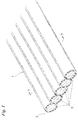
- Fig. 1 which illustrates an embodiment of the present invention, is a partially enlarged perspective view of a strip-shaped steel cord 1.
- Fig. 2 is a sectional view taken along line II-II of Fig. 1 .
- the strip-shaped steel cord 1 has five core wires 2 arrayed in parallel with one another in a plane, and an adhesive (adhesive layer) 3 which fixes the five core wires 2 into a unitary body and maintains the parallel array thereof.
- the core wires 2 are made of steel and contain carbon and iron.
- the adhesive 3 is rubber-based and has styrene-butadiene, nitrile, chloroprene or the like as its main ingredient.
- Each of the core wires 2 constituting the strip-shaped steel cord 1 has a circular cross section with use being made of wire having a wire diameter (the cross-sectional diameter of the core wire 2) of 0.15 to 0.45 mm.
- the core wire 2 is fabricated by subjecting piano wire having a wire diameter of 5.50 mm to dry wire drawing and heat treatment a required number of times, brass-plating the wire and then performing wet wire drawing in the order mentioned.
- the five core wires are arranged in parallel with one another in a plane without being twisted, are coated with the adhesive 3 and shaped to thereby produce the strip-shaped steel cord 1.
- Thickness Ad of the applied adhesive 3 is made less than 15 ⁇ m.
- wire diameter d of the core wire 2 is 0.20 mm, for example, the width of the steel cord 1 will be about 1.00 mm. It should be understood that the perspective view of the strip-shaped steel cord 1 shown in Fig. 1 and the sectional view shown in Fig. 2 are illustrated in considerably enlarged form.
- the adjacent core wires 2 may be made to contact each other along the longitudinal direction (in which case the spacing Gd between the mutually adjacent core wires would be 0).
- the spacing Gd between the mutually adjacent core wires is made less than 20 ⁇ m, as will be described later.
- the five core wires 2 constituting the strip-shaped steel cord 1 are fixed and united into a whole by the adhesive 3, enabling the parallel array to be stably maintained.
- the strip-shaped steel cord 1 is wound upon a reel and shipped to an automobile tire factory or the like.
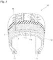
- Fig. 3 is a sectional view illustrating the structure of an automobile tire 10.
- the automobile tire 10 has a carcass 12 that will form the skeletal frame of the tire 10, annular beads situated at both ends of the carcass 12, and a tread portion 14 situated on the outermost layer of the automobile tire 10.
- Two belt layers 11a, 11b are situated between the carcass 12 and tread portion 14.
- the strip-shaped steel cord 1 is used upon being embedded in the belt layers 11a, 11b.
- the carcass 12 is tightened by the belt layers 11a, 11b, whereby the rigidity of the tire 10 is enhanced. Further, the belt layers 11a, 11b alleviate impact from the road surface and also prevent external damage from directly reaching the carcass 12.
- the strip-shaped steel cord 1 described above was subjected to an evaluation test from a variety of standpoints. The evaluation test will be described in detail below.
- Table 1 illustrates results of the evaluation test. Strip-shaped steel cords of multiple types obtained by making various changes in parameters (structure) described below were fabricated and each strip-shaped steel cord was subjected to the evaluation test. TABLE 1 WRAPPING WIRE DIAMETER d FREE COIL DIAMETER D D/d WIRE SPACING ADHESIVE THICKNESS SHAPE STABILITY RUBBER ADHESION DURABILITY FRETTING RESISTANCE AH H COMPARATIVE EXAMPLE 1 STEEL 0.2mm 200mm 1000 3 ⁇ m - ⁇ ⁇ 100 ⁇ 12mm 0mm COMPARATIVE EXAMPLE 2 PA66 0.2 200 1000 5 - ⁇ ⁇ 105 ⁇ 14 0 COMPARATIVE EXAMPLE 3 PET 0.2 200 1000 6 - ⁇ ⁇ 103 ⁇ 14 0 COMPARATIVE EXAMPLE 4 - 0.2 100 500 15 10 ⁇ m ⁇ ⁇ 112 ⁇ 47 9 COMPARATIVE EXAMPLE 5 - 0.2 100 500 15
- Samples of strip-shaped steel cords were fabricated, these being obtained by winding a wrapping wire helically about the periphery of five core wires 2 to unit the wires in the manner of the prior art (for example, see Japanese Patent Application Laid-Open No. 62-149929 ) rather than uniting them by the adhesive 3 (Comparative Examples 1 to 3).
- a steel wrapping wire was used in Comparative Example 1, a PA66 (polyamide 66) wrapping wire in Comparative Example 2, and a PET (polyethylene-terephthalate) wrapping wire in Comparative Example 3. All samples other than Comparative Examples 1 to 3 (namely Comparative Examples 4 to 29 and Embodiments 1 to 12) were strip-shaped steel cords 1 ( Figs. 1 and 2 ) in which the five core wires 2 were united by the adhesive 3 without using wrapping wire.
- Wire diameter is the wire diameter (cross-sectional diameter) of the core wire 2.
- the strip-shaped steel cords 1 were fabricated changing the wire diameter d of the core wire 2 (see Fig. 2 ) over a range of 0.15 to 0.5 mm.
- Free coil diameter refers to the diameter of a coil (a ring-shaped configuration) that forms naturally in the absence of an acting external force when the wire is left at rest on a flat surface.
- the core wire 2 is fabricated through a wire drawing process, as described above, and develop kinks when passing through the die used in the drawing process. As a consequence, the core wire does not necessarily assume a linear shape when not being acted upon by an external force.
- the free coil diameter can be controlled by controlling the shape of the wire-drawing exit of the die and by adjusting the angle of the die. In the evaluation test, the free coil diameter was changed over a range of 100 to 550 mm.
- the adhesive thickness was changed over a range of 10 to 20 ⁇ m.
- the above-mentioned wire spacing Gd and adhesive thickness Ad were measured using sectional photographs obtained by enlarged imaging of the cross section of the fabricated strip-shaped steel cord 1.
- Table 1 illustrates six types of evaluation, namely "SHAPE STABILITY”, “RUBBER ADHESION”, “DURABILITY”, “FRETTING RESISTANCE”, “AH” (curling evaluation value)” and “H” (sheet-flatness evaluation value).
- the strip-shaped steel cord 1 is required to be one that can maintain its shape continuously until the rubber and the strip-shaped steel cord 1 are adhered together in a calendaring process. Evaluation of shape stability was carried out using a testing apparatus shown in Fig. 4 .
- the testing apparatus includes a supply reel 4 for supplying the steel cord 1, a take-up reel 5 for taking up the steel cord 1, five upper-stage guide rolls 6 of diameter 50 mm provided at intervals on a straight line between the two reels 4 and 5, and five lower-stage guide rolls 7 of diameter 50 mm provided at intervals on a straight line between the two reels 4 and 5.
- the height positions of the upper-stage guide rolls 6 and lower-stage guide rolls 7 were adjusted in such a manner that 6 mm of vertical motion (pressing force) was applied to the steel cord 1 when the steel cord 1 passed between the upper-stage guide rolls 6 and lower-stage guide rolls 7.
- the steel cord 1 was supplied from the supply reel 4 at a supply tension of 2 kgf, was passed between the guide rolls 6, 7 at a speed of 30 m/min and was wound up on the take-up reel 5. Thereafter the steel cord 1 was visually inspected.
- an "x” is indicated with regard to samples for which loss of shape of the steel cord 1, such as separation of adhesive (disorder in the parallel array), was confirmed, and an “o” is indicated with regard to samples for which loss of shape was not confirmed.
- the symbols “o” and “x” are used to express a high evaluation (or that the sample is suitable) and a low evaluation (or that the sample is unsuitable), respectively.
- the belt layers 11a, 11b in which the strip-shaped steel cord 1 was embedded were made of rubber. It is required that the steel cord 1 adhere to the belt layers (rubber) 11 a, 11b favorably.
- the surface of the core wires 2 constituting the strip-shaped steel cord 1 were brass-plated. If the core wires 2 and belt layers 11a, 11b are in direct contact, the core wires and belt layers will adhere together favorably because an interfacial reaction occurs at the time of vulcanization (vulcanizing molding performed at the final stage of the tire manufacturing process) owing to copper contained in the brass plating and sulfur contained in the rubber.
- the strip-shaped steel cord 1 was provided on its outermost surface with the adhesive 3, as described above (see Figs.
- the core wires 2 (the brass plating layer on the surface thereof) and the belt layers 11a, 11b (rubber) do not come into direct contact. Accordingly, the adhesion between the strip-shaped steel cord 1 and the belt layers 11a, 11b must be carefully ascertained.
- the evaluation of rubber adhesion means, in other words, evaluation of the adhesion between the strip-shaped steel cord 1 and the belt layers 11a, 11b. The evaluation of rubber adhesion was performed in line with ASTM (American Society of Testing and Materials) D2229.
- the periphery of the strip-shaped steel cord 1 was covered with rubber, the rubber was subjected to vulcanizing molding, the steel cord 1 was pulled out of the vulcanized rubber and the percentage of the area of the surface of the extracted steel cord 1 covered with the rubber (the rubber coverage) was measured.
- the rubber adhesion evaluation column of Table 1 an "o” is indicated with regard to samples for which the rubber coverage was 75% or greater, and an "x” is indicated with regard to samples for which the rubber coverage was less than 75%.
- the strip-shaped steel cord 1 embedded in the belt layers 11 a, 11b of the automobile tire 10 snaps (breaks), the strip-shaped steel cord 1 will no longer function as a reinforcing member for the automobile tire 10. Rubbing between the core wires 2 that constitute the steel cord 1 and mutually sustained wear can cause the strip-shaped steel cord 1 to snap.
- the evaluations of durability and fretting resistance were conducted using a three-roll testing machine shown in Fig. 5 and a test piece 30 shown in Fig. 6 in enlarged form.
- the three-roll testing machine has a driving unit 20 that includes a total of three freely rotatable rolls, namely two freely rotatable rolls 21, 23 disposed on a straight line, and a freely rotatable roll 22 disposed between the freely rotatable rolls 21, 23 at a position offset from the straight line.
- the test piece 30 in which the steel cord 1 was embedded (see Fig. 6 ) was engaged with the rolls 21, 22, 23 of the driving unit 20 and the driving unit 20 (the three rolls 21, 22, 23) were moved back and forth along the direction of the straight line.
- the driving unit 20 was moved back and forth at a speed of 320 cycles/min, and one stroke was 180 mm.
- the test piece 30 was obtained by covering the strip-shaped steel cord 1, which had an overall length of 1200 mm, with rubber in quadrate form having a length of 350 mm, a height of 4.5 mm and a width of 9.5 mm.
- the strip-shaped steel cord 1 was exposed at both ends of the test piece 30.
- One end of the strip-shaped steel cord 1 was screwed securely to a fixture 25 and a weight 24 exerting a load that was 10% of the severance load of strip-shaped steel cord 1 was suspended from the other end.
- the number of reciprocations (the number of total-rupture cycles) of the driving unit 20 obtained at rupture of the entire strip-shaped steel cord 1 embedded in the test piece 30 is indicated by an index with Comparative Example 1 serving as 100.
- the fretting-resistance evaluation column of Table 1 testing was halted at a cycle count that was 80% of the number of total-rupture cycles obtained in the durability evaluation test, the test piece 30 was taken apart and the absence or presence of wear on the surface of the steel cord 1 was observed. The results are shown in the fretting-resistance evaluation column of Table 1. An "x" is indicated with regard to a sample for which wear was confirmed, and an "o” is indicated with regard to samples for which wear was not confirmed.
- the core wire 2 constituting the strip-shaped steel cord 1 is fabricated through a wire drawing process, as described above, the core wire will not necessarily be linear when an external force is not acting upon them. Further, since the strip-shaped steel cord 1 obtained by fixing the five core wires 2 in a state in which they are arranged in parallel is shipped and stored, etc., in a state in which it is wound upon a reel, as mentioned above, the steel cord is imparted with kinks while it is being wound upon the reel. If the strip-shaped steel cord 1 develops a large amount of winding kink, there are instances where curling occurs in a calendar sheet at a preliminary stage for manufacture of the belt layers 11a, 11b.
- the strip-shaped steel cord 1 was wound at a tension of 1.2 kgf upon a reel having a drum diameter of 114 mm, this was left standing for two weeks and the strip-shaped steel cord 1 was then fed from the reel.
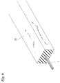
- the amount of curvature of this strip-shaped steel cord 1 is indicated in the AH column of Table 1. With the strip-shaped steel cord 1 cut to 400 mm as shown in Fig.
- the curvature quantity AH is the distance from the intersection between a straight line, which connects both ends of the strip-shaped steel cord 1 and a perpendicular dropped from the apex of the strip-shaped steel cord 1, to the apex.
- AH was measured in compliance with JIS (Japan Industrial Standards) G3510. AH values equal to or greater than 40 mm are indicated by boldface characters in the AH column of Table 1.
- the calendar sheet in which the steel cord has been embedded will curl, as mentioned above.
- the extend of curling of a rubber sheet covering the strip-shaped steel cord 1 (after it was wound upon a reel having a drum diameter of 114 mm and left standing for two weeks).
- An unvulcanized rubber sheet of length 1000 mm x width 100 mm x thickness 0.5 mm was wound upon a drum having a circumference of 1000 mm (and a diameter of about 320 mm), and the strip-shaped steel cord 1 was wound regularly upon the unvulcanized rubber sheet at a tension of 2 kgf.
- An unvulcanized rubber sheet of the same size was further wound upon the steel cord from above to thereby sandwich the strip-shaped steel cord 1. This was followed by crimping at a load of 6 kgf using a roll to thereby fabricate a composite sheet 40.
- the composite sheet 40 was cut in a direction perpendicular to the cord, the composite sheet 40 was taken off the drum and left at rest on a flat surface, then the amount of uplift (distance from the flat surface) at the four corners of the composite sheet 40 was measured.
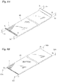
- Fig. 8A is a perspective view of the composite sheet 40.
- Fig. 8B illustrates the composite sheet 40 of Fig. 8A after it has been turned over.
- characters reading "TOP” are shown on the composite sheet 40 of Fig. 8A
- characters reading "BOTTOM” are shown on the composite sheet 40 of Fig. 8B .
- the composite sheet 40 illustrated in Fig. 8A is such that an AB end and a CD end thereof are curled upward (this is somewhat emphasized in the drawing).
- the turned-over composite sheet 40 shown in Fig. 8B is substantially free of curling. The reason for this is that, when the composite sheet 40 with its ends curled upwardly as shown in Fig. 8A is turned over and left at rest on a flat surface, the sheet comes to lie flat along the flat surface owing to dead weight of the composite sheet 40.
- H Ah + Bh + Ch + Dh + Arh + Brh + Crh + Drh /
- fretting resistance was "x" for the strip-shaped steel cord (Comparative Example 1) obtained by helically winding the steel wrapping wire about the periphery of the five core wires 2 arrayed in parallel. It is believed that this is on account of strong tightening of the core wires 2 by the steel wrapping wire, which results in the core wires 2 rubbing strongly against one another.
- fretting resistance was "o" for all of the strip-shaped steel cords (Comparative Examples 2 and 3) obtained by helically winding wrapping wire made of PA66 or PET and strip-shaped steel cords (Comparative Examples 3 to 29 and Embodiments 1 to 12) obtained by fixing the five core wires into a unitary body by adhesive.
- the strip-shaped steel cords 1 (Comparative Examples 3 to 29 and Embodiments 1 to 12) obtained by fixing the five core wires 2 into a unitary body by adhesive exhibit better durability than the strip-shaped steel cords (Comparative Examples 2 and 3) obtained by helically winding wrapping wire made of PA66 or PET.
- the durability and fretting resistance of the strip-shaped steel cord 1 can be improved more by fixing the core wires 2 into a unitary body using adhesive than by fixing the core wires 2 into a unitary body using wrapping wire.
- Fig. 9 illustrates shape stability evaluation (o or x) regarding the Comparative Examples 3 to 29 and Embodiments 1 to 12, which are shown in Table 1, plotted on a graph in which the horizontal axis indicates free coil diameter / wire diameter (D/d) and the vertical axis indicates wire spacing Gd.
- the evaluation of shape stability is "x" when the value of D/d is less than 750. Further, the evaluation of shape stability is "x", even if the value of D/d is equal to or greater than 750, when the wire spacing is equal to or greater than 20 ⁇ m. It was confirmed that when the value of D/d is equal to or greater than 750 (the free coil diameter D of the core wire 2 is greater than the wire diameter d by 750 times or more) and, moreover, the wire spacing is less than 20 ⁇ m, shape stability of the strip-shaped steel cord 1 is achieved.
- Fig. 10 is a plot of evaluation of rubber adhesion (o or x) regarding the Comparative Examples 3 to 29 and Embodiments 1 to 12, which are shown in Table 1, on a graph in which the horizontal axis indicates wire diameter d and the vertical axis indicates thickness Ad of the adhesive 3.
- the evaluation of rubber adhesion is "x" when the thickness of the adhesive 3 is equal to or greater than 15 ⁇ m.
- the evaluation of rubber adhesion is "o" when the thickness of the adhesive 3 is less than 15 ⁇ m.
- Fig. 11 illustrates a graph relating to evaluation of sheet flatness based upon the test results in Table 1.
- the horizontal axis indicates the curvature quantity AH of the strip-shaped steel cord 1 and the vertical axis indicates the sheet uplift quantity
- "x" is plotted with regard to steel cord for which the sheet uplift quantity H exceeds 5 mm
- "o" is plotted with regard to steel cord for which the sheet uplift quantity H is equal to or less than 5 mm.
- Fig. 12 illustrates a graph relating to evaluation of winding kink.
- the sheet uplift quantity H exceeds 5 mm for a composite sheet 40 (see Figs. 8A, 8B ) using the strip-shaped steel cord 1 having a curvature quantity AH (see Fig. 7 ) equal to or greater than 40 mm. Further, it was confirmed that when the curvature quantity AH of the strip-shaped steel cord 1 exceeds 40 mm, the sheet uplift quantity H of the composite sheet 40 starts to increase sharply. The sheet uplift quantity H falls below 5 mm if the curvature quantity AH is less than 40 mm. It was confirmed that the sheet uplift quantity H is strongly dependent the curvature quantity AH of the strip-shaped steel cord 1.
- the curvature quantity AH of the strip-shaped steel cord 1 is equal to or greater than 40 mm when the value of the free coil diameter / wire diameter (D/d) is less than 750 or the wire diameter is equal to or greater than 0.45 mm. It was confirmed that if the value of the free coil diameter / wire diameter (D/d) is equal to or greater than 750 and, moreover, the wire diameter is less than 0.45 mm, then the curvature quantity AH of the strip-shaped steel cord 1 is less than 40 mm.
- the sheet uplift quantity H of the composite sheet 40 is held below 5 mm.
- the value of D/d be made equal to or greater than 750 (that the free coil diameter of the core wire 2 be made greater than the wire diameter d by 750 times or more) and, moreover, that the wire spacing Gd between mutually adjacent core wires 2 be made less than 20 ⁇ m in order to obtain excellent shape stability of the steel cord to be manufactured.
- the thickness Ad of the adhesive 3 be made less than 15 ⁇ m.
- the value of D/d be made equal to or greater than 750 (that the free coil diameter of the core wire 2 be made greater than the wire diameter d by 750 times or more) and, moreover, that the wire diameter d be made less than 0.45 mm.
Landscapes
- Engineering & Computer Science (AREA)
- Mechanical Engineering (AREA)
- Textile Engineering (AREA)
- Ropes Or Cables (AREA)
- Tires In General (AREA)
Abstract
Description
- This invention relates to a strip-shaped steel cord.
- In order to extend the life, improve the kinematic performance, reduce the weight and lower the cost of automobile tires, it is known to embed a steel cord, in which multiple wires made of steel are arrayed in parallel with one another, in the belt layer that constitutes the tire.
-
Patent Document 1 discloses a steel cord in which a steel wrapping wire is wound helically on multiple steel wires arrayed in parallel with one another. Accordingly, if the binding force produced by the steel wrapping wire is too great, a strong contact pressure acts between the multiple steel wires, fretting wear develops at the time of use (when the vehicle is traveling with the tire mounted) and there is the danger of a decline in durability.Patent Document 2 discloses an arrangement in which multiple steel wires are wrapped by an organic fiber rather than by a steel wrapping wire. However, since organic fiber has much less rigidity in comparison with steel, there is the danger that the force that maintains the parallel arrangement of the multiple steel wires will be inadequate. If the number of steel wires to be arrayed in parallel is large, loss of shape is especially likely to occur. - Arrangements in which multiple wires (filaments) are united in parallel with one another using an adhesive rather than a wrapping wire have been proposed (
Patent Documents 3 and 4). - Maintaining multiple steel wires in a mutually parallel state using an adhesive rather than by winding a wrapping wire around them eliminates the need to consider the magnitude of binding force and the like that should be taken into consideration when use is made of a wrapping wire. If an adhesive is used, however, the adhesion between steel wires provided by the adhesive must be taken into account as a matter of course. In addition, since the adhesive lies between the steel cord and the rubber, it is necessary to consider the rubber adhesion with respect to the steel cord when the steel cord is embedded within the rubber (the belt layer). It is of course necessary to also consider the relationship between the adhesive strength afforded by the adhesive and the repulsive force of the steel cord (a force that flexure) in order to assure shape stability.
- Patent Document 1:
Japanese Patent Application Laid-Open No. 62-149929 - Patent Document 2:
Japanese Patent Application Laid-Open No. 2001-55008 - Patent Document 3:
Japanese Patent Application Laid-Open No. 63-240402 - Patent Document 4:
Japanese Patent Application Laid-Open No. 7-304307 - An object of the present invention is to improve the durability and shape stability of steel cord.
- A further object of the present invention is to prevent an extreme decline in rubber adhesion in a steel cord in which multiple steel wires are maintained in parallel with one another using an adhesive.
- Yet another object of the present invention is to suppress, to the maximum extent, the repulsive force of a steel cord in which multiple steel wires are maintained in parallel with one another using an adhesive, and prevent the occurrence of a large amount of curling of a rubber sheet in which the steel cord has been embedded.
- A steel cord in accordance with the present invention has an external form that is strip-shaped overall (a slender, planar shape), in which multiple brass-plated steel core wires arrayed in parallel with one another are bundled together with the parallel array being maintained intact. The strip-shaped steel cord according to the present invention is such that the wire diameter (cross-sectional diameter) of each of the core wires is less than 0.45 mm, the surface thereof is coated with an adhesive to a thickness of less than 15 µm, the multiple core wires are fixed together into a unitary body by the adhesive, the spacing between mutually adjacent core wires is less than 20 µm, and free coil diameter of each of the core wires [the diameter of a coil (a ring-shaped configuration) that forms naturally in the absence of an acting external force when the wire is left at rest on a flat surface] is greater than the wire diameter by 750 times or more.
- In accordance with the present invention, multiple core wires are adhered together by an adhesive, whereby the parallel array of the multiple core wires is maintained. Since the core wires are fixed into a unitary body owing to the adhesion provided by the adhesive, there is no enlargement of contact pressure between the core wires and there is hardly any fretting wear caused by core wires rubbing against each other. A highly durable steel cord is provided.
- The steel cord in accordance with the present invention is used upon being embedded within a rubber sheet. In order to heighten the adhesion between the steel cord and rubber, the surface of the core wires constituting the steel cord is plated with brass. In the steel cord according to the present invention, the thickness of the adhesive applied to the surface in order to fix the multiple core wires into a unitary body is made less than 15 µm. By making the thickness of the adhesive less than 15 µm, it is possible to suppress a decline in adhesion between the steel cord and the rubber that is ascribable to the interposition of the adhesive.
- The steel cord in accordance with the present invention is constituted by core wires each having a wire diameter of less than 0.45 mm and a free coil diameter that is greater than the wire diameter by 750 times or more. When a curved (twisted) steel cord is embedded in a rubber sheet, the rubber sheet curls owing to the embedded steel cord. By using core wires each having a wire diameter of less than 0.45 mm and a free coil diameter that is greater than the wire diameter by 750 times or more, curling produced in the rubber sheet having the embedded steel cord can be made comparatively small.
- The steel cord in accordance with the present invention is such that the spacing between mutually adjacent core wires is made less than 20 µm. By using core wires in which the spacing of the mutually adjacent core wires is less than 20 µm and the free coil diameter thereof is greater than the wire diameter by 750 times or more, separation of the adhered portions hardly occurs, the parallel array of the multiple core wires can be maintained and shape stability is improved.
- It should be noted that if the wire diameter of each of the core wires is too small (the core wire is too slender), there is the possibility that the desired strength will not be attainable. It is preferred, therefore, that the wire diameter of each of the core wires be equal to or greater than 0.15 mm.
- The present invention also provides a belt layer for tires in which the above-described steel cord is embedded, as well as a tire equipped with this belt layer.
-
-
Fig. 1 is a partially enlarged perspective view of a strip-shaped steel cord; -
Fig. 2 is a sectional view of the strip-shaped steel cord taken along line II-II ofFig. 1 ; -
Fig. 3 is a sectional view illustrating the internal structure of a tire for automobiles; -
Fig. 4 schematically illustrates a testing machine used in evaluating shape stability; -
Fig. 5 schematically illustrates a three-roll testing machine; -
Fig. 6 is a perspective view of a test piece in a three-roll test; -
Fig. 7 illustrates a point where amount of curvature is measured in a winding-kink evaluation test; -
Fig. 8A is a perspective view illustrating a composite sheet, which is used in a flatness evaluation test, from a top side; -
Fig. 8B is a perspective view illustrating the composite sheet, which is used in the flatness evaluation test, from a bottom side; -
Fig. 9 is a graph relating to evaluation of shape stability; -
Fig. 10 is a graph relating to evaluation of rubber adhesion; -
Fig. 11 is a graph relating to sheet flatness; and -
Fig. 12 is a graph relating to evaluation of winding kink. -
Fig. 1 , which illustrates an embodiment of the present invention, is a partially enlarged perspective view of a strip-shaped steel cord 1.Fig. 2 is a sectional view taken along line II-II ofFig. 1 . - The strip-
shaped steel cord 1 has fivecore wires 2 arrayed in parallel with one another in a plane, and an adhesive (adhesive layer) 3 which fixes the fivecore wires 2 into a unitary body and maintains the parallel array thereof. Thecore wires 2 are made of steel and contain carbon and iron. Theadhesive 3 is rubber-based and has styrene-butadiene, nitrile, chloroprene or the like as its main ingredient. - Each of the
core wires 2 constituting the strip-shaped steel cord 1 has a circular cross section with use being made of wire having a wire diameter (the cross-sectional diameter of the core wire 2) of 0.15 to 0.45 mm. For example, thecore wire 2 is fabricated by subjecting piano wire having a wire diameter of 5.50 mm to dry wire drawing and heat treatment a required number of times, brass-plating the wire and then performing wet wire drawing in the order mentioned. The five core wires are arranged in parallel with one another in a plane without being twisted, are coated with theadhesive 3 and shaped to thereby produce the strip-shaped steel cord 1. Thickness Ad of the appliedadhesive 3 is made less than 15 µm. If wire diameter d of thecore wire 2 is 0.20 mm, for example, the width of thesteel cord 1 will be about 1.00 mm. It should be understood that the perspective view of the strip-shapedsteel cord 1 shown inFig. 1 and the sectional view shown inFig. 2 are illustrated in considerably enlarged form. - With reference to
Fig. 2 , there is a minute spacing Gd between the fiveadjacent core wires 2 constituting the strip-shapedsteel cord 1, and the adhesive 3 is present in the gaps Gd as well. It should be noted that theadjacent core wires 2 may be made to contact each other along the longitudinal direction (in which case the spacing Gd between the mutually adjacent core wires would be 0). The spacing Gd between the mutually adjacent core wires is made less than 20 µm, as will be described later. In any case, the fivecore wires 2 constituting the strip-shapedsteel cord 1 are fixed and united into a whole by the adhesive 3, enabling the parallel array to be stably maintained. - After the adhesive 3 hardens, the strip-shaped
steel cord 1 is wound upon a reel and shipped to an automobile tire factory or the like. -
Fig. 3 is a sectional view illustrating the structure of anautomobile tire 10. Theautomobile tire 10 has acarcass 12 that will form the skeletal frame of thetire 10, annular beads situated at both ends of thecarcass 12, and atread portion 14 situated on the outermost layer of theautomobile tire 10. Twobelt layers carcass 12 andtread portion 14. The strip-shapedsteel cord 1 is used upon being embedded in the belt layers 11a, 11b. Thecarcass 12 is tightened by the belt layers 11a, 11b, whereby the rigidity of thetire 10 is enhanced. Further, the belt layers 11a, 11b alleviate impact from the road surface and also prevent external damage from directly reaching thecarcass 12. - The strip-shaped
steel cord 1 described above was subjected to an evaluation test from a variety of standpoints. The evaluation test will be described in detail below. - Table 1 illustrates results of the evaluation test. Strip-shaped steel cords of multiple types obtained by making various changes in parameters (structure) described below were fabricated and each strip-shaped steel cord was subjected to the evaluation test.
TABLE 1 WRAPPING WIRE DIAMETER d FREE COIL DIAMETER D D/d WIRE SPACING ADHESIVE THICKNESS SHAPE STABILITY RUBBER ADHESION DURABILITY FRETTING RESISTANCE AH H COMPARATIVE EXAMPLE 1 STEEL 0.2mm 200mm 1000 3µm - ○ ○ 100 × 12mm 0mm COMPARATIVE EXAMPLE 2 PA66 0.2 200 1000 5 - × ○ 105 ○ 14 0 COMPARATIVE EXAMPLE 3 PET 0.2 200 1000 6 - × ○ 103 ○ 14 0 COMPARATIVE EXAMPLE 4 - 0.2 100 500 15 10µm × ○ 112 ○ 47 9 COMPARATIVE EXAMPLE 5 - 0.2 100 500 15 20 × × 112 ○ 47 9 COMPARATIVE EXAMPLE 6 - 0.2 100 500 20 10 × ○ 111 ○ 48 9 COMPARATIVE EXAMPLE 7 - 0.2 100 500 20 20 × × 111 ○ 47 9 COMPARATIVE EXAMPLE 8 - 0.2 140 700 15 10 × ○ 113 ○ 40 6 COMPARATIVE EXAMPLE 9 - 0.2 150 750 20 20 × × 112 ○ 31 3 COMPARATIVE EXAMPLE 10 - 0.2 200 1000 15 15 ○ × 114 ○ 15 1 COMPARATIVE EXAMPLE 11 - 0.2 200 1000 15 20 ○ × 113 ○ 15 1 COMPARATIVE EXAMPLE 12 - 0.2 200 1000 20 10 × ○ 112 ○ 16 1 COMPARATIVE EXAMPLE 13 - 0.2 200 1000 25 10 × ○ 110 ○ 16 1 COMPARATIVE EXAMPLE 14 - 0.3 210 700 5 13 × ○ 114 ○ 41 6 COMPARATIVE EXAMPLE 15 - 0.3 240 800 5 18 ○ × 115 ○ 31 3 COMPARATIVE EXAMPLE 16 - 0.3 330 1100 15 20 ○ × 113 ○ 22 1 COMPARATIVE EXAMPLE 17 - 0.3 330 1100 20 13 × ○ 112 ○ 23 1 COMPARATIVE EXAMPLE 18 - 0.4 280 700 10 13 × ○ 112 ○ 44 7 COMPARATIVE EXAMPLE 19 - 0.4 300 750 10 15 ○ × 1 5 ○ 36 4 COMPARATIVE EXAMPLE 20 - 0.4 480 1200 15 20 ○ × 1 4 ○ 28 1 COMPARATIVE EXAMPLE 21 - 0.4 480 1200 20 20 × × 112 ○ 28 1 COMPARATIVE EXAMPLE 22 - 0.47 400 851 15 10 ○ × 115 ○ 50 10 COMPARATIVE EXAMPLE 23 - 0.47 500 1064 15 15 ○ ○ 115 ○ 49 10 COMPARATIVE EXAMPLE 24 - 0.47 500 1064 20 15 × × 114 ○ 49 10 COMPARATIVE EXAMPLE 25 - 0.5 350 700 20 10 × ○ 113 ○ 54 17 COMPARATIVE EXAMPLE 26 - 0.5 400 800 20 15 × x 113 ○ 53 15 COMPARATIVE EXAMPLE 27 - 0.5 500 1000 15 10 ○ ○ 116 ○ 52 14 COMPARATIVE EXAMPLE 28 - 0.5 550 1100 15 15 ○ × 115 ○ 52 14 COMPARATIVE EXAMPLE 29 - 0.5 550 1100 20 15 × × 113 ○ 52 14 EMBODIMENT 1 - 0.15 200 1333 15 10 ○ ○ 109 ○ 8 0 EMBODIMENT 2 - 0.2 150 750 15 10 ○ ○ 1 3 ○ 31 3 EMBODIMENT 3 - 0.2 160 800 15 10 ○ ○ 1 2 ○ 27 2 EMBODIMENT 4 - 0.2 200 1000 15 10 ○ ○ 113 ○ 15 1 EMBODIMENT 5 - 0.2 200 1000 15 13 ○ ○ 115 ○ 15 1 EMBODIMENT 6 - 0.2 200 1000 15 14 ○ ○ 113 ○ 15 1 EMBODIMENT 7 - 0.2 200 1000 18 10 ○ ○ 112 ○ 16 1 EMBODIMENT 8 - 0.2 200 1000 19 10 ○ ○ 111 ○ 16 1 EMBODIMENT 9 - 0.3 300 1000 15 10 ○ ○ 116 ○ 24 1 EMBODIMENT 10 - 0.4 400 1000 15 10 ○ ○ 116 ○ 34 2 EMBODIMENT 11 - 0.45 340 756 15 10 ○ ○ 114 ○ 39 5 EMBODIMENT 12 - 0 45 400 889 15 10 ○ ○ 114 ○ 39 5 - Samples of strip-shaped steel cords were fabricated, these being obtained by winding a wrapping wire helically about the periphery of five
core wires 2 to unit the wires in the manner of the prior art (for example, seeJapanese Patent Application Laid-Open No. 62-149929 Embodiments 1 to 12) were strip-shaped steel cords 1 (Figs. 1 and2 ) in which the fivecore wires 2 were united by the adhesive 3 without using wrapping wire. - Wire diameter is the wire diameter (cross-sectional diameter) of the
core wire 2. The strip-shapedsteel cords 1 were fabricated changing the wire diameter d of the core wire 2 (seeFig. 2 ) over a range of 0.15 to 0.5 mm. - Free coil diameter refers to the diameter of a coil (a ring-shaped configuration) that forms naturally in the absence of an acting external force when the wire is left at rest on a flat surface. The
core wire 2 is fabricated through a wire drawing process, as described above, and develop kinks when passing through the die used in the drawing process. As a consequence, the core wire does not necessarily assume a linear shape when not being acted upon by an external force. The free coil diameter can be controlled by controlling the shape of the wire-drawing exit of the die and by adjusting the angle of the die. In the evaluation test, the free coil diameter was changed over a range of 100 to 550 mm. - This is a so-called spring index which, in this embodiment, is used to express the repulsive force of the core wire 2 (a force producing flexure and deviating away from the linear state) by a numerical value. This is a value obtained by dividing the above-mentioned free coil diameter D by the wire diameter d.
- This is the spacing Gd between mutually adjacent core wires 2 (see
Fig. 2 ). In the evaluation test, the strip-shapedsteel cords 1 were fabricated changing the wire spacing Gd over a range of 3 to 25 µm. - This is thickness Ad of the adhesive 3 applied to the surface of the core wires 2 (see
Figs. 1 and2 ). The adhesive thickness was changed over a range of 10 to 20 µm. The above-mentioned wire spacing Gd and adhesive thickness Ad were measured using sectional photographs obtained by enlarged imaging of the cross section of the fabricated strip-shapedsteel cord 1. - Table 1 illustrates six types of evaluation, namely "SHAPE STABILITY", "RUBBER ADHESION", "DURABILITY", "FRETTING RESISTANCE", "AH" (curling evaluation value)" and "H" (sheet-flatness evaluation value).
- The strip-shaped
steel cord 1 is required to be one that can maintain its shape continuously until the rubber and the strip-shapedsteel cord 1 are adhered together in a calendaring process. Evaluation of shape stability was carried out using a testing apparatus shown inFig. 4 . The testing apparatus includes asupply reel 4 for supplying thesteel cord 1, a take-upreel 5 for taking up thesteel cord 1, five upper-stage guide rolls 6 ofdiameter 50 mm provided at intervals on a straight line between the tworeels diameter 50 mm provided at intervals on a straight line between the tworeels steel cord 1 when thesteel cord 1 passed between the upper-stage guide rolls 6 and lower-stage guide rolls 7. Thesteel cord 1 was supplied from thesupply reel 4 at a supply tension of 2 kgf, was passed between the guide rolls 6, 7 at a speed of 30 m/min and was wound up on the take-upreel 5. Thereafter thesteel cord 1 was visually inspected. In the shape-stability evaluation column of Table 1, an "x" is indicated with regard to samples for which loss of shape of thesteel cord 1, such as separation of adhesive (disorder in the parallel array), was confirmed, and an "o" is indicated with regard to samples for which loss of shape was not confirmed. In this specification, the symbols "o" and "x" are used to express a high evaluation (or that the sample is suitable) and a low evaluation (or that the sample is unsuitable), respectively. - The belt layers 11a, 11b in which the strip-shaped
steel cord 1 was embedded were made of rubber. It is required that thesteel cord 1 adhere to the belt layers (rubber) 11 a, 11b favorably. As mentioned above, the surface of thecore wires 2 constituting the strip-shapedsteel cord 1 were brass-plated. If thecore wires 2 andbelt layers steel cord 1 was provided on its outermost surface with the adhesive 3, as described above (seeFigs. 1 and2 ), the core wires 2 (the brass plating layer on the surface thereof) and the belt layers 11a, 11b (rubber) do not come into direct contact. Accordingly, the adhesion between the strip-shapedsteel cord 1 and the belt layers 11a, 11b must be carefully ascertained. The evaluation of rubber adhesion means, in other words, evaluation of the adhesion between the strip-shapedsteel cord 1 and the belt layers 11a, 11b. The evaluation of rubber adhesion was performed in line with ASTM (American Society of Testing and Materials) D2229. Specifically, the periphery of the strip-shapedsteel cord 1 was covered with rubber, the rubber was subjected to vulcanizing molding, thesteel cord 1 was pulled out of the vulcanized rubber and the percentage of the area of the surface of the extractedsteel cord 1 covered with the rubber (the rubber coverage) was measured. In the rubber adhesion evaluation column of Table 1, an "o" is indicated with regard to samples for which the rubber coverage was 75% or greater, and an "x" is indicated with regard to samples for which the rubber coverage was less than 75%. - If the strip-shaped
steel cord 1 embedded in the belt layers 11 a, 11b of theautomobile tire 10 snaps (breaks), the strip-shapedsteel cord 1 will no longer function as a reinforcing member for theautomobile tire 10. Rubbing between thecore wires 2 that constitute thesteel cord 1 and mutually sustained wear can cause the strip-shapedsteel cord 1 to snap. The evaluations of durability and fretting resistance were conducted using a three-roll testing machine shown inFig. 5 and atest piece 30 shown inFig. 6 in enlarged form. - The three-roll testing machine has a driving
unit 20 that includes a total of three freely rotatable rolls, namely two freely rotatable rolls 21, 23 disposed on a straight line, and a freelyrotatable roll 22 disposed between the freely rotatable rolls 21, 23 at a position offset from the straight line. Thetest piece 30 in which thesteel cord 1 was embedded (seeFig. 6 ) was engaged with therolls unit 20 and the driving unit 20 (the three rolls 21, 22, 23) were moved back and forth along the direction of the straight line. Therolls central roll 22 and rolls 21, 23 on both sides. The drivingunit 20 was moved back and forth at a speed of 320 cycles/min, and one stroke was 180 mm. Thetest piece 30 was obtained by covering the strip-shapedsteel cord 1, which had an overall length of 1200 mm, with rubber in quadrate form having a length of 350 mm, a height of 4.5 mm and a width of 9.5 mm. The strip-shapedsteel cord 1 was exposed at both ends of thetest piece 30. One end of the strip-shapedsteel cord 1 was screwed securely to afixture 25 and aweight 24 exerting a load that was 10% of the severance load of strip-shapedsteel cord 1 was suspended from the other end. - In the durability evaluation column of Table 1, the number of reciprocations (the number of total-rupture cycles) of the driving
unit 20 obtained at rupture of the entire strip-shapedsteel cord 1 embedded in thetest piece 30 is indicated by an index with Comparative Example 1 serving as 100. With regard to the fretting-resistance evaluation column of Table 1, testing was halted at a cycle count that was 80% of the number of total-rupture cycles obtained in the durability evaluation test, thetest piece 30 was taken apart and the absence or presence of wear on the surface of thesteel cord 1 was observed. The results are shown in the fretting-resistance evaluation column of Table 1. An "x" is indicated with regard to a sample for which wear was confirmed, and an "o" is indicated with regard to samples for which wear was not confirmed. - Since the
core wire 2 constituting the strip-shapedsteel cord 1 is fabricated through a wire drawing process, as described above, the core wire will not necessarily be linear when an external force is not acting upon them. Further, since the strip-shapedsteel cord 1 obtained by fixing the fivecore wires 2 in a state in which they are arranged in parallel is shipped and stored, etc., in a state in which it is wound upon a reel, as mentioned above, the steel cord is imparted with kinks while it is being wound upon the reel. If the strip-shapedsteel cord 1 develops a large amount of winding kink, there are instances where curling occurs in a calendar sheet at a preliminary stage for manufacture of the belt layers 11a, 11b. If the calendar sheet curls, there is the danger that an impediment will occur in the process for manufacturing the belt layers 11a, 11b from the calendar sheet. The strip-shapedsteel cord 1 was wound at a tension of 1.2 kgf upon a reel having a drum diameter of 114 mm, this was left standing for two weeks and the strip-shapedsteel cord 1 was then fed from the reel. The amount of curvature of this strip-shapedsteel cord 1 is indicated in the AH column of Table 1. With the strip-shapedsteel cord 1 cut to 400 mm as shown inFig. 7 placed on a flat surface, the curvature quantity AH is the distance from the intersection between a straight line, which connects both ends of the strip-shapedsteel cord 1 and a perpendicular dropped from the apex of the strip-shapedsteel cord 1, to the apex. AH was measured in compliance with JIS (Japan Industrial Standards) G3510. AH values equal to or greater than 40 mm are indicated by boldface characters in the AH column of Table 1. - If the strip-shaped
steel cord 1 develops a large amount of winding kink, the calendar sheet in which the steel cord has been embedded will curl, as mentioned above. In the evaluation of sheet flatness, what was evaluated was the extend of curling of a rubber sheet covering the strip-shaped steel cord 1 (after it was wound upon a reel having a drum diameter of 114 mm and left standing for two weeks). An unvulcanized rubber sheet oflength 1000mm x width 100 mm x thickness 0.5 mm was wound upon a drum having a circumference of 1000 mm (and a diameter of about 320 mm), and the strip-shapedsteel cord 1 was wound regularly upon the unvulcanized rubber sheet at a tension of 2 kgf. An unvulcanized rubber sheet of the same size was further wound upon the steel cord from above to thereby sandwich the strip-shapedsteel cord 1. This was followed by crimping at a load of 6 kgf using a roll to thereby fabricate acomposite sheet 40. Thecomposite sheet 40 was cut in a direction perpendicular to the cord, thecomposite sheet 40 was taken off the drum and left at rest on a flat surface, then the amount of uplift (distance from the flat surface) at the four corners of thecomposite sheet 40 was measured. -
Fig. 8A is a perspective view of thecomposite sheet 40.Fig. 8B illustrates thecomposite sheet 40 ofFig. 8A after it has been turned over. In order to facilitate understanding, characters reading "TOP" are shown on thecomposite sheet 40 ofFig. 8A and characters reading "BOTTOM" are shown on thecomposite sheet 40 ofFig. 8B . Thecomposite sheet 40 illustrated inFig. 8A is such that an AB end and a CD end thereof are curled upward (this is somewhat emphasized in the drawing). By contrast, the turned-overcomposite sheet 40 shown inFig. 8B is substantially free of curling. The reason for this is that, when thecomposite sheet 40 with its ends curled upwardly as shown inFig. 8A is turned over and left at rest on a flat surface, the sheet comes to lie flat along the flat surface owing to dead weight of thecomposite sheet 40. - Let Ah, Bh, Ch and Dh represent the amounts of uplift (distances from the flat surface) of four corners A, B, C and D, respectively, of the
composite sheet 40 that has not been turned over (Fig. 8A ). Let Arh, Brh, Crh and Drh represent the amounts of uplift of the four corners A, B, C and D, respectively, of thecomposite sheet 40 that has been turned over (Fig. 8B ). A value calculated according to the following equation is used as the uplift quantity H of the composite sheet 40:
- Numerical values of the uplift quantity H calculated according to the above-cited calculation equation are indicated in the H column of Table 1. Further, numerical values of the uplift quantity H that exceed 5 mm are represented by the boldface characters.
- With reference to the evaluation column for fretting resistance in Table 1, it will be seen that the evaluation of fretting resistance was "x" for the strip-shaped steel cord (Comparative Example 1) obtained by helically winding the steel wrapping wire about the periphery of the five
core wires 2 arrayed in parallel. It is believed that this is on account of strong tightening of thecore wires 2 by the steel wrapping wire, which results in thecore wires 2 rubbing strongly against one another. The evaluation of fretting resistance was "o" for all of the strip-shaped steel cords (Comparative Examples 2 and 3) obtained by helically winding wrapping wire made of PA66 or PET and strip-shaped steel cords (Comparative Examples 3 to 29 andEmbodiments 1 to 12) obtained by fixing the five core wires into a unitary body by adhesive. - With reference to the durability evaluation column of Table 1, it is assumed that "100" is the durability of the strip-shaped steel cord obtained by winding steel wrapping wire of Comparative Example 1. It will be seen that the durabilities of the strip-shaped steel cords (Comparative Examples 2 and 3), which were obtained by helically winding wrapping wire made of PA66 or PET, and of the strip-shaped steel cords (Comparative Examples 3 to 29 and
Embodiments 1 to 12), which were obtained by fixing the fivecore wires 2 into a unitary body by adhesive, all exceeded "100". Further, it was confirmed that the strip-shaped steel cords 1 (Comparative Examples 3 to 29 andEmbodiments 1 to 12) obtained by fixing the fivecore wires 2 into a unitary body by adhesive exhibit better durability than the strip-shaped steel cords (Comparative Examples 2 and 3) obtained by helically winding wrapping wire made of PA66 or PET. - It was confirmed that the durability and fretting resistance of the strip-shaped
steel cord 1 can be improved more by fixing thecore wires 2 into a unitary body using adhesive than by fixing thecore wires 2 into a unitary body using wrapping wire. - Next, with reference to the shape-stability evaluation column of Table 1, it will be seen that although the evaluation of shape stability was "o" when steel wire was used as the wrapping wire (Comparative Example 1), the evaluation of shape stability was "x" when PA66 or PET wire was used as the wrapping wire (Comparative Examples 2, 3). It is believed that PA66 and PET exert insufficient force for maintaining the five
core wires 2 in the parallel-arrayed state. - On the other hand, with regard to the strip-shaped steel cords 1 (Comparative Examples 3 to 29 and
Embodiments 1 to 12) obtained by fixing the fivecore wires 2 into a unitary body by adhesive, it was confirmed that the evaluation of shape stability is affected by the values of free coil diameter / wire diameter (D/d) and wire spacing Gd. -
Fig. 9 illustrates shape stability evaluation (o or x) regarding the Comparative Examples 3 to 29 andEmbodiments 1 to 12, which are shown in Table 1, plotted on a graph in which the horizontal axis indicates free coil diameter / wire diameter (D/d) and the vertical axis indicates wire spacing Gd. - With reference to the graph of
Fig. 9 , the evaluation of shape stability is "x" when the value of D/d is less than 750. Further, the evaluation of shape stability is "x", even if the value of D/d is equal to or greater than 750, when the wire spacing is equal to or greater than 20 µm. It was confirmed that when the value of D/d is equal to or greater than 750 (the free coil diameter D of thecore wire 2 is greater than the wire diameter d by 750 times or more) and, moreover, the wire spacing is less than 20 µm, shape stability of the strip-shapedsteel cord 1 is achieved. Specifically, in order to assure the binding force between thecore wires 2 resulting from the adhesive 3 and maintain shape stability, it is required that the repulsive force of the core wires not be made too large (thatcore wire 2 having a small D/d not be used), and it is required that the wire spacing Gd between thecore wires 2 not be made too great. - Next, with reference to the rubber-adhesion evaluation column, it was confirmed that the evaluation of rubber adhesion is influenced by the thickness Ad of the adhesive 3.
-
Fig. 10 is a plot of evaluation of rubber adhesion (o or x) regarding the Comparative Examples 3 to 29 andEmbodiments 1 to 12, which are shown in Table 1, on a graph in which the horizontal axis indicates wire diameter d and the vertical axis indicates thickness Ad of the adhesive 3. The evaluation of rubber adhesion is "x" when the thickness of the adhesive 3 is equal to or greater than 15 µm. On the other hand, the evaluation of rubber adhesion is "o" when the thickness of the adhesive 3 is less than 15 µm. Although it was found that the reaction between the surface (the layer of brass plating) of thecore wires 2 and rubber is impeded by the presence of the adhesive 3, it was confirmed that the impediment to the reaction is comparatively suppressed by limiting the thickness of the adhesive 3 to less than 15 µm. -
Fig. 11 illustrates a graph relating to evaluation of sheet flatness based upon the test results in Table 1. On the graph, in which the horizontal axis indicates the curvature quantity AH of the strip-shapedsteel cord 1 and the vertical axis indicates the sheet uplift quantity, "x" is plotted with regard to steel cord for which the sheet uplift quantity H exceeds 5 mm and "o" is plotted with regard to steel cord for which the sheet uplift quantity H is equal to or less than 5 mm.Fig. 12 illustrates a graph relating to evaluation of winding kink. On the graph, in which the horizontal axis indicates the free coil diameter / wire diameter (D/d) and the vertical axis indicates the wire diameter d, "x" is plotted with regard to steel cord for which the curvature quantity AH is equal to or greater than 40 mm and "o" is plotted with regard to steel cord for which the curvature quantity AH is less than 40 mm. - With reference to
Fig. 11 , the sheet uplift quantity H exceeds 5 mm for a composite sheet 40 (seeFigs. 8A, 8B ) using the strip-shapedsteel cord 1 having a curvature quantity AH (seeFig. 7 ) equal to or greater than 40 mm. Further, it was confirmed that when the curvature quantity AH of the strip-shapedsteel cord 1 exceeds 40 mm, the sheet uplift quantity H of thecomposite sheet 40 starts to increase sharply. The sheet uplift quantity H falls below 5 mm if the curvature quantity AH is less than 40 mm. It was confirmed that the sheet uplift quantity H is strongly dependent the curvature quantity AH of the strip-shapedsteel cord 1. - With reference to
Fig. 12 , the curvature quantity AH of the strip-shapedsteel cord 1 is equal to or greater than 40 mm when the value of the free coil diameter / wire diameter (D/d) is less than 750 or the wire diameter is equal to or greater than 0.45 mm. It was confirmed that if the value of the free coil diameter / wire diameter (D/d) is equal to or greater than 750 and, moreover, the wire diameter is less than 0.45 mm, then the curvature quantity AH of the strip-shapedsteel cord 1 is less than 40 mm. That is, when the value of the free coil diameter / wire diameter (D/d) is equal to or greater than 750 (the free coil diameter D of thecore wire 2 is 750 times the wire diameter d or more) and, moreover, the wire diameter d is less than 0.45 mm, the sheet uplift quantity H of thecomposite sheet 40 is held below 5 mm. - In summary with regard to the above-described results of the evaluation tests, it is required that the value of D/d be made equal to or greater than 750 (that the free coil diameter of the
core wire 2 be made greater than the wire diameter d by 750 times or more) and, moreover, that the wire spacing Gd between mutuallyadjacent core wires 2 be made less than 20 µm in order to obtain excellent shape stability of the steel cord to be manufactured. In order to obtain excellent adhesion between the strip-shapedsteel cord 1 and the belt layers 11 a, 11b, it is required that the thickness Ad of the adhesive 3 be made less than 15 µm. Furthermore, in order to hold curling of thecomposite sheet 40, in which the strip-shapedsteel cord 1 has been embedded, to within 5 mm to thereby assure flatness, it is required that the value of D/d be made equal to or greater than 750 (that the free coil diameter of thecore wire 2 be made greater than the wire diameter d by 750 times or more) and, moreover, that the wire diameter d be made less than 0.45 mm.
Claims (4)
- A strip-shaped steel cord in which multiple brass-plated steel core wires arrayed in parallel with one another are bundled with said parallel array being maintained intact, characterized in that:wire diameter of each of said core wires is less than 0.45 mm;the surface thereof is coated with an adhesive to a thickness of less than 15 µm and the multiple core wires are fixed together into a unitary body by said adhesive;spacing between mutually adjacent core wires is less than 20 µm; andfree coil diameter of each of said core wires is greater than the wire diameter by 750 times of more.
- A strip-shaped steel cord according to claim 1, wherein said wire diameter is equal to or greater than 0.15 mm.
- A belt layer for tires, said belt layer having embedded therein the strip-shaped steel cord set forth in claim 1 or 2.
- A tire having the belt layer for tires set forth in claim 3.
Applications Claiming Priority (2)
| Application Number | Priority Date | Filing Date | Title |
|---|---|---|---|
| JP2013133259A JP5995793B2 (en) | 2013-06-26 | 2013-06-26 | Strip steel cord |
| PCT/JP2014/066508 WO2014208480A1 (en) | 2013-06-26 | 2014-06-23 | Strip-shaped steel cord |
Publications (2)
| Publication Number | Publication Date |
|---|---|
| EP3015599A1 true EP3015599A1 (en) | 2016-05-04 |
| EP3015599A4 EP3015599A4 (en) | 2017-01-25 |
Family
ID=50920467
Family Applications (1)
| Application Number | Title | Priority Date | Filing Date |
|---|---|---|---|
| EP14816602.8A Withdrawn EP3015599A4 (en) | 2013-06-26 | 2014-06-23 | Strip-shaped steel cord |
Country Status (8)
| Country | Link |
|---|---|
| US (1) | US9862234B2 (en) |
| EP (1) | EP3015599A4 (en) |
| JP (1) | JP5995793B2 (en) |
| KR (1) | KR101788994B1 (en) |
| CN (2) | CN203654057U (en) |
| CA (1) | CA2933314C (en) |
| TW (1) | TWI526337B (en) |
| WO (1) | WO2014208480A1 (en) |
Cited By (1)
| Publication number | Priority date | Publication date | Assignee | Title |
|---|---|---|---|---|
| EP4088921A3 (en) * | 2021-05-11 | 2022-11-23 | Sumitomo Rubber Industries, Ltd. | Method of manufacturing rubber composite and method of manufacturing tire |
Families Citing this family (12)
| Publication number | Priority date | Publication date | Assignee | Title |
|---|---|---|---|---|
| JP5995793B2 (en) * | 2013-06-26 | 2016-09-21 | 東京製綱株式会社 | Strip steel cord |
| JP6444192B2 (en) * | 2015-01-30 | 2018-12-26 | 株式会社ブリヂストン | Pneumatic tires for motorcycles |
| US10821690B2 (en) * | 2015-06-29 | 2020-11-03 | Bridgestone Corporation | Tire and method for manufacturing tire |
| JP6681704B2 (en) * | 2015-12-01 | 2020-04-15 | 株式会社ブリヂストン | Steel cord for tire reinforcement and tire using the same |
| JP6830019B2 (en) * | 2017-04-06 | 2021-02-17 | 株式会社ブリヂストン | Resin metal composite members for tires and tires |
| WO2018198240A1 (en) * | 2017-04-26 | 2018-11-01 | 三菱電機株式会社 | Elevator, suspension body therefor, and production method for suspension body |
| JP6993872B2 (en) * | 2017-12-28 | 2022-01-14 | Toyo Tire株式会社 | How to manufacture tire belts |
| WO2020080438A1 (en) * | 2018-10-17 | 2020-04-23 | 株式会社ブリヂストン | Elastomer-metal cord composite body and tire using same |
| US20210379932A1 (en) * | 2018-10-17 | 2021-12-09 | Bridgestone Corporation | Elastomer-metal cord composite body, and tire using same |
| JP7806402B2 (en) * | 2021-06-22 | 2026-01-27 | 住友ゴム工業株式会社 | tire |
| EP4370741A1 (en) * | 2021-07-13 | 2024-05-22 | NV Bekaert SA | A steel cord for rubber reinforcement |
| JP7367899B1 (en) * | 2023-02-24 | 2023-10-24 | 住友電気工業株式会社 | Steel cord, cord-rubber composite, tire |
Family Cites Families (19)
| Publication number | Priority date | Publication date | Assignee | Title |
|---|---|---|---|---|
| GB1400626A (en) * | 1971-06-21 | 1975-07-16 | Bridgestone Tire Co Ltd | Composite of a metallic material and vulcanized rubber and process for production thereof |
| GB1547773A (en) * | 1975-06-05 | 1979-06-27 | Bekaert Sa Nv | Reinforcement of resilient articles |
| US4756970A (en) * | 1985-02-11 | 1988-07-12 | The Goodyear Tire & Rubber Company | Metallic cable |
| JPH0663187B2 (en) | 1985-12-23 | 1994-08-17 | 東京製鋼株式会社 | Steel cord for reinforcing plastics |
| JPS63240402A (en) | 1986-10-10 | 1988-10-06 | エヌ・ヴイ・ベカルト・エス・エイ | Reinforcing strip |
| JP3177382B2 (en) * | 1994-05-09 | 2001-06-18 | 住友ゴム工業株式会社 | Tire reinforcement cord and pneumatic tire using the same |
| JP3838455B2 (en) * | 1997-04-18 | 2006-10-25 | 株式会社ブリヂストン | Pneumatic radial tire |
| ES2257779T3 (en) | 1997-09-25 | 2006-08-01 | Bridgestone Corporation | STEEL ROPE, PROCEDURE FOR THE MANUFACTURE OF THE SAME AND PNEUMATIC. |
| JP4471242B2 (en) | 1999-08-12 | 2010-06-02 | 株式会社ブリヂストン | Pneumatic radial tire |
| JP2001322404A (en) * | 2000-05-12 | 2001-11-20 | Bridgestone Corp | Pneumatic radial tire |
| DE60113006T2 (en) * | 2000-05-12 | 2006-03-16 | Bridgestone Corp. | Radial tire |
| JP4015379B2 (en) | 2001-06-01 | 2007-11-28 | 住友ゴム工業株式会社 | Steel cord for reinforcing rubber, method for producing steel cord for reinforcing rubber, and pneumatic tire |
| DE60238610D1 (en) | 2001-07-19 | 2011-01-27 | Pirelli | TIRES FOR MOTOR VEHICLES WITH WAVY MONOFILAMENTS IN BELT REINFORCEMENT LAYER |
| EP1967645B1 (en) * | 2005-12-01 | 2012-01-11 | Sumitomo Rubber Industries, Ltd. | Metallic cord, rubber/cord composite object, and pneumatic tire obtained using the same |
| JP2008025040A (en) * | 2006-07-18 | 2008-02-07 | Tokyo Seiko Co Ltd | Steel cord and manufacturing method thereof |
| JP2008200737A (en) | 2007-02-22 | 2008-09-04 | Bridgestone Corp | Method of manufacturing reinforcing material for rubber goods |
| CN101457493B (en) * | 2007-12-14 | 2012-05-02 | 上海三菱电梯有限公司 | Flat cables and elevator devices for elevators |
| JP2012121324A (en) * | 2010-11-18 | 2012-06-28 | Bridgestone Corp | Method of manufacturing rubber sheet |
| JP5995793B2 (en) * | 2013-06-26 | 2016-09-21 | 東京製綱株式会社 | Strip steel cord |
-
2013
- 2013-06-26 JP JP2013133259A patent/JP5995793B2/en active Active
- 2013-09-27 CN CN201320604544.XU patent/CN203654057U/en not_active Expired - Lifetime
- 2013-09-27 CN CN201310452914.7A patent/CN104250940B/en active Active
- 2013-10-30 TW TW102139370A patent/TWI526337B/en active
-
2014
- 2014-06-23 EP EP14816602.8A patent/EP3015599A4/en not_active Withdrawn
- 2014-06-23 CA CA2933314A patent/CA2933314C/en active Active
- 2014-06-23 KR KR1020167001858A patent/KR101788994B1/en active Active
- 2014-06-23 US US14/392,312 patent/US9862234B2/en active Active
- 2014-06-23 WO PCT/JP2014/066508 patent/WO2014208480A1/en not_active Ceased
Non-Patent Citations (1)
| Title |
|---|
| See references of WO2014208480A1 * |
Cited By (1)
| Publication number | Priority date | Publication date | Assignee | Title |
|---|---|---|---|---|
| EP4088921A3 (en) * | 2021-05-11 | 2022-11-23 | Sumitomo Rubber Industries, Ltd. | Method of manufacturing rubber composite and method of manufacturing tire |
Also Published As
| Publication number | Publication date |
|---|---|
| CN104250940A (en) | 2014-12-31 |
| TWI526337B (en) | 2016-03-21 |
| JP2015007299A (en) | 2015-01-15 |
| EP3015599A4 (en) | 2017-01-25 |
| KR101788994B1 (en) | 2017-10-20 |
| US20160193878A1 (en) | 2016-07-07 |
| TW201500235A (en) | 2015-01-01 |
| WO2014208480A1 (en) | 2014-12-31 |
| CN104250940B (en) | 2017-10-13 |
| KR20160023836A (en) | 2016-03-03 |
| CA2933314A1 (en) | 2014-12-31 |
| JP5995793B2 (en) | 2016-09-21 |
| US9862234B2 (en) | 2018-01-09 |
| CA2933314C (en) | 2018-02-13 |
| CN203654057U (en) | 2014-06-18 |
Similar Documents
| Publication | Publication Date | Title |
|---|---|---|
| EP3015599A1 (en) | Strip-shaped steel cord | |
| US7870715B2 (en) | Steel cord | |
| WO2007116857A1 (en) | Bead cord and vehicle tire | |
| EP3009560B1 (en) | Method of manufacturing a steel cord for a tire reinforcement | |
| JP2010089727A (en) | Pneumatic tire and its manufacturing method | |
| CN101838873A (en) | Steel cord for reinforcing rubber products and manufacturing method thereof | |
| JP2008260409A (en) | Pneumatic radial tire for large vehicles | |
| JPH08120578A (en) | Steel cord for reinforcing rubber | |
| JP5656346B2 (en) | Method for producing rubber-steel cord composite | |
| JP6077315B2 (en) | Steel cord, manufacturing method thereof, and pneumatic tire using the same | |
| JPH1088488A (en) | Steel cords for rubber reinforcement and radial tires | |
| JP2008025040A (en) | Steel cord and manufacturing method thereof | |
| JP7540621B1 (en) | Steel cord, cord-rubber composite, and tire | |
| WO2024224687A1 (en) | Cord-rubber composite, method for producing cord-rubber composite, and tire | |
| JP4669405B2 (en) | Manufacturing method of rubber sheet as tire reinforcing material and tire using rubber sheet manufactured by the manufacturing method | |
| KR100267283B1 (en) | Steel cord twisted with wire having different flat surface angle periodically | |
| JP2009084727A (en) | Rubber-steel cord composite, method for producing the same, and pneumatic tire using the same | |
| JP4014959B2 (en) | Steel cord for tire reinforcement | |
| WO2024176640A1 (en) | Steel cord, cord-rubber composite, and tire | |
| JP3484626B2 (en) | Steel cord and tire radial tire for tire reinforcement | |
| JP3590690B2 (en) | Steel cord for reinforcing rubber products | |
| JP2013040428A (en) | Rubber-coated steel cord and method for manufacturing steel cord band for rubber crawler | |
| JPH1053982A (en) | Steel cord for reinforcing rubber product | |
| JP2006249636A (en) | Steel cord | |
| JP2006089902A (en) | Metal cord for reinforcing rubber article and method for producing the same cord |
Legal Events
| Date | Code | Title | Description |
|---|---|---|---|
| PUAI | Public reference made under article 153(3) epc to a published international application that has entered the european phase |
Free format text: ORIGINAL CODE: 0009012 |
|
| 17P | Request for examination filed |
Effective date: 20151223 |
|
| AK | Designated contracting states |
Kind code of ref document: A1 Designated state(s): AL AT BE BG CH CY CZ DE DK EE ES FI FR GB GR HR HU IE IS IT LI LT LU LV MC MK MT NL NO PL PT RO RS SE SI SK SM TR |
|
| AX | Request for extension of the european patent |
Extension state: BA ME |
|
| DAX | Request for extension of the european patent (deleted) | ||
| A4 | Supplementary search report drawn up and despatched |
Effective date: 20170103 |
|
| RIC1 | Information provided on ipc code assigned before grant |
Ipc: D07B 1/06 20060101AFI20161221BHEP Ipc: D02G 3/48 20060101ALI20161221BHEP Ipc: B60C 9/00 20060101ALI20161221BHEP Ipc: D02G 3/36 20060101ALI20161221BHEP Ipc: D02G 3/12 20060101ALI20161221BHEP Ipc: B32B 15/01 20060101ALI20161221BHEP Ipc: B60C 9/20 20060101ALI20161221BHEP Ipc: D07B 1/16 20060101ALI20161221BHEP |
|
| 17Q | First examination report despatched |
Effective date: 20170929 |
|
| GRAP | Despatch of communication of intention to grant a patent |
Free format text: ORIGINAL CODE: EPIDOSNIGR1 |
|
| INTG | Intention to grant announced |
Effective date: 20180309 |
|
| STAA | Information on the status of an ep patent application or granted ep patent |
Free format text: STATUS: THE APPLICATION HAS BEEN WITHDRAWN |
|
| 18W | Application withdrawn |
Effective date: 20180530 |