EP3015033B1 - Elektrischer druckkochtopf - Google Patents
Elektrischer druckkochtopf Download PDFInfo
- Publication number
- EP3015033B1 EP3015033B1 EP14818746.1A EP14818746A EP3015033B1 EP 3015033 B1 EP3015033 B1 EP 3015033B1 EP 14818746 A EP14818746 A EP 14818746A EP 3015033 B1 EP3015033 B1 EP 3015033B1
- Authority
- EP
- European Patent Office
- Prior art keywords
- cooker
- electric pressure
- cover
- pressure cooker
- magnetic
- Prior art date
- Legal status (The legal status is an assumption and is not a legal conclusion. Google has not performed a legal analysis and makes no representation as to the accuracy of the status listed.)
- Active
Links
Images


Classifications
-
- A—HUMAN NECESSITIES
- A47—FURNITURE; DOMESTIC ARTICLES OR APPLIANCES; COFFEE MILLS; SPICE MILLS; SUCTION CLEANERS IN GENERAL
- A47J—KITCHEN EQUIPMENT; COFFEE MILLS; SPICE MILLS; APPARATUS FOR MAKING BEVERAGES
- A47J27/00—Cooking-vessels
- A47J27/08—Pressure-cookers; Lids or locking devices specially adapted therefor
- A47J27/0802—Control mechanisms for pressure-cookers
-
- A—HUMAN NECESSITIES
- A47—FURNITURE; DOMESTIC ARTICLES OR APPLIANCES; COFFEE MILLS; SPICE MILLS; SUCTION CLEANERS IN GENERAL
- A47J—KITCHEN EQUIPMENT; COFFEE MILLS; SPICE MILLS; APPARATUS FOR MAKING BEVERAGES
- A47J27/00—Cooking-vessels
- A47J27/08—Pressure-cookers; Lids or locking devices specially adapted therefor
- A47J27/09—Safety devices
Definitions
- the present invention relates to the field of household appliances, and particularly relates to an electric pressure cooker.
- the CN 201 312 728 Y utility model discloses an electric pressure cooker, comprising a surface cover, an inner cover, a shell hood, a shell hood cover board and an outer cooker, wherein the shell hood is fixedly arranged on the outer cooker; the outer shell hood cover board is fixedly arranged on the shell hood; the surface cover and the inner cover are arranged at the upper end of the outer cooker, wherein a magnet or a micro-switch is arranged between the surface cover and the inner cover; the shell hood cover board is provided with a micro-switch or a magnet corresponding to the position of the magnet or the micro-switch when the cover is closed in place.
- a touch part for controlling the power connection or switching off of the micro-switch is arranged between the micro-switch and the magnet.
- the micro-switch is connected with a control circuit for controlling the electric pressure cooker.
- the control circuit is power on and the electric pressure cooker starts working.
- the micro-switch is cut off and the control circuit is power off automatically, thus avoiding accidents caused by cooker cover not in place or displacement during work and ensuring the safe use of the product.
- the present invention aims to at least solve one of the technical problems in the prior art.
- the present invention needs to provide an electric pressure cooker, which is provided with a magnetic sensitive switch and a magnetic member which constitute a detection device for detecting whether a cooker cover is closed in place or not.
- the electric pressure cooker is simple in structure and low in manufacturing cost.
- the electric pressure cooker includes a cooker body and a cooker cover, wherein the cooker body is provided with a magnetic sensitive switch and a magnetic member, and the magnetic member can move between a first position and a second position relative to the magnetic sensitive switch so that a control circuit of the electric pressure cooker can be powered on or powered off; and the cooker cover is arranged on the cooker body, and can rotate relative to the cooker body so that the magnetic member can move between the first position and the second position.
- the magnetic member moves through arrangement of the magnetic sensitive switch and the magnetic member and through rotation of the cooker cover, so that the distance between the magnetic sensitive switch and the magnetic member is changed, and then power-on and power-off of the electric circuit of the electric pressure cooker can be controlled, that is to say, the magnetic sensitive switch and the magnetic member can constitute a detection device of the electric pressure cooker for detecting whether the cover is closed in place; and compared with a cover-closing in-place detection device in the prior art, the combination of the magnetic sensitive switch and the magnetic member is simple in structure and low in manufacturing cost.
- the cooker body includes a housing, an inner cooker and a housing cover, wherein the inner cooker is arranged in the housing, an accommodating cavity is defined between the housing and the inner cooker, and the magnetic sensitive switch is arranged in the accommodating cavity; and the housing cover is sleeved outside the inner cooker and closes the accommodating cavity.
- the electric pressure cooker further includes a mounting member, the magnetic member is arranged on the mounting member, the mounting member can move up and down relative to the housing cover, and according to the invention the upper end of the mounting member penetrates through the housing cover so as to match the cooker cover.
- the electric pressure cooker according to the present invention may also have the following additional technical features.
- a guide post which extends downwards is arranged on the lower surface of the housing cover;
- the mounting member includes a body and a push rod, wherein the body is provided with a positioning hole matched with the guide post, and the magnetic member is arranged in the body;
- the push rod is arranged on the body and the upper end of the push rod penetrates through the housing cover and extends upwards;
- the electric pressure cooker further includes an elastic member, the lower end of the elastic member is positioned on the guide post and the upper end of the elastic member presses against the body.
- the electric pressure cooker further includes a screw, the screw is arranged on the guide post, and the lower end of the elastic member presses against the head end of the screw.
- the elastic member is a spring, and the spring is sleeved outside the guide post.
- An annular convex rib is arranged at the lower part of the cooker cover and provided with a yielding port capable of accommodating the push rod.
- a water retaining part is also arranged in the accommodating cavity, a relatively closed accommodating space is defined between the water retaining part and the wall of the accommodating cavity, and the magnetic sensitive switch is arranged in the accommodating space.
- An accommodating groove for placing the magnetic member is formed in the body, and positioning buckles for positioning the magnetic member are arranged on the accommodating groove.
- the magnetic member is a magnet.
- orientations or positional relations indicated by terms “upper”, “lower”, “inner”, “outer” and the like are the ones shown on the basis of the accompanying drawings, and are merely used for conveniently describing the present invention and simplifying the description, rather than indicating or implying that the indicated devices or components must have specific orientations and are constructed and operated according to the specific orientations, so they can not be understood as limit to the present invention.
- terms “first” and “second” are merely used for the purpose of description, rather than indicating or implying the relative importance or the number of indicated technical features.
- the features defined by “first” and “second” may explicitly or implicitly include one or more features.
- "a plurality of' indicates two or more unless otherwise noted.
- connection may be fixed connection, detachable connection, integral connection, mechanical connection, electrical connection, direct connection, indirect connection by virtue of inter-media or communication between the inner parts of two components.
- connection may be fixed connection, detachable connection, integral connection, mechanical connection, electrical connection, direct connection, indirect connection by virtue of inter-media or communication between the inner parts of two components.
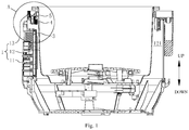
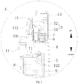
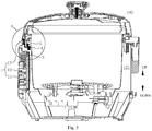
- the electric pressure cooker 100 according to an embodiment of the present invention will be described with reference to Fig. 1 to Fig. 9 .
- the electric pressure cooker 100 according to the embodiment of the present invention includes a cooker body 1 and a cooker cover 2.
- the cooker cover 2 is arranged on the cooker body 1, wherein the cooker cover 2 may be detachably arranged on the cooker body 1, namely the cooker cover 2 may be taken down from the cooker cover 2, and specifically, the cooker cover 2 and the cooker body 1 may be connected with each other through a cover tooth structure (not shown), a buckle, a clamping jaw or the like. Moreover, the cooker cover 2 may also be connected to the cooker body 1 all the time without being detached, e.g. the cooker cover 2 may be connected to the cooker body 1 through a hinge and the like, and when the cover needs to be opened, the cooker cover 2 may be opened in a turnover manner.
- the cooker cover 2 When the cooker cover 2 is arranged on the cooker body 1, the cooker cover 2 may rotate relative to the cooker body 1. Specifically, when the cooker cover 2 and the cooker body 1 are of a detachable structure and a user needs to buckle the cooker cover 2 for cooking, the cooker cover 2 may be first placed on the cooker body 1, and then the cooker cover 2 is rotated to cover the cooker body 1 in place for cooking.
- a hinge may be arranged between the cooker cover 2 and the cooker body 1 for connection; when being opened, the cooker cover 2 may be connected to the cooker body 1 all the time, so that the cooker cover 2 is prevented from being lost or falling from a table top; and the cooker cover 2 may rotate relative to the cooker body 1 during closing through self rotation of the cooker cover. Because this structure belongs to the prior art, it will not be described in detail.
- a magnetic sensitive switch 3 and a magnetic member 4 are arranged on the cooker body 1, and the magnetic member 4 can move between a first position and a second position relative to the magnetic sensitive switch 3 so that a control circuit of the electric pressure cooker 100 can be powered on or powered off, namely an electric circuit of the electric pressure cooker 100 can be powered on or powered off.
- the control circuit of the electric pressure cooker 100 is powered on, and the electric pressure cooker 100 can be used for cooking; and when the magnetic member 4 is at the second position relative to the magnetic sensitive switch 3, as shown in Fig. 3 and Fig. 4 , the control circuit of the electric pressure cooker 100 is powered off, and the electric pressure cooker 100 can not be used for cooking.
- the magnetic sensitive switch 3 detects the change of a magnetic field around it and outputs a level
- a controller detects the high or low level output by the magnetic sensitive switch 3 to control power-on and power-off of the circuit, namely when the magnetic sensitive switch 3 detects that the magnetic field is intensified, the magnetic sensitive switch 3 outputs the high level, and the controller controls the electric circuit of the electric pressure cooker 100 to be powered off; and when the magnetic sensitive switch 3 detects that the magnetic field is weakened, the magnetic sensitive switch 3 outputs the low level, and the controller controls the electric circuit of the electric pressure cooker 100 to be powered on.
- the magnetic sensitive switch 3 detects that the magnetic field is weakened and the magnetic sensitive switch 3 outputs the low level, the electric circuit of the electric pressure cooker 100 is powered on, namely the electric pressure cooker 100 can be electrified to work.
- the magnetic sensitive switch 3 detects that the magnetic field is intensified and the magnetic sensitive switch 3 outputs the high level, the electric circuit of the electric pressure cooker 100 is powered off, namely the electric pressure cooker 100 can not work.
- the distance between the magnetic member 4 and the magnetic sensitive switch 3 may be relatively long; and when the magnetic member 4 is at the second position relative to the magnetic sensitive switch 3, the distance between the magnetic member 4 and the magnetic sensitive switch 3 may be relatively short.
- the purpose that the magnetic sensitive switch 3 can detect the magnetic field with different intensity may be achieved.
- the magnetic member 4 can move between the first position and the second position. Specifically, when the cooker cover 2 rotates and is closed in place, the cooker cover 2 can enable the magnetic member 4 to be at the first position, so the electric circuit of the electric pressure cooker 100 is powered on; and when the cooker cover 2 is not closed in place, the cooker cover 2 can enable the magnetic member 4 to be at the second position, so the electric circuit of the electric pressure cooker 100 is powered off.
- the magnetic member 4 moves through the arrangement of the magnetic sensitive switch 3 and the magnetic member 4 and through the rotation of the cooker cover 2, so that the distance between the magnetic sensitive switch 3 and the magnetic member 4 is changed, and then power-on and power-off of the electric circuit of the electric pressure cooker 100 can be controlled, that is to say, the magnetic sensitive switch 3 and the magnetic member 4 can constitute a detection device of the electric pressure cooker 100 for detecting whether the cover is closed in place; and compared with a cover-closing in-place detection device in the prior art, the combination of the magnetic sensitive switch 3 and the magnetic member 4 is simple in structure and low in manufacturing cost.
- the magnetic member 4 may be a magnet.
- the cooker body 1 may include a housing 11, an inner cooker 12 and a housing cover 13. As shown in Fig. 1 to Fig. 6 , the inner cooker 12 is arranged in the housing 11, an inner container (not shown) may be placed in the inner cooker 12, and food materials may be placed in the inner container for cooking. An accommodating cavity 121 is defined between the housing 11 and the inner cooker 12, and the magnetic sensitive switch 3 is arranged in the accommodating cavity 121. It could be understood that, parts constituting the electric system of the electric pressure cooker 100 may also be arranged in the accommodating cavity 121.
- the housing cover 13 is sleeved outside the inner cooker 12 and closes the accommodating cavity 121, and the cooker cover 2 may be arranged on the housing cover 13 and rotate on the housing cover 13.
- the electric pressure cooker 100 further includes a mounting member 5, the magnetic member 4 is arranged on the mounting member 5, the mounting member 5 can move up and down relative to the housing cover 13 of the cooker body 1, and therefore the magnetic member 4 can move between the first position and the second position through up-and-down movement of the mounting member 5. That is to say, as shown in Fig. 1 to Fig. 6 , when the mounting member 5 moves downwards, the magnetic member 4 also moves downwards, and then the magnetic member 4 moves downwards from the first position to the second position.
- the magnetic sensitive switch 3 is positioned below the magnetic member 4, and the distance between the magnetic sensitive switch 3 and the magnetic member 4 is shortened when the magnetic member 4 moves downwards from the first position to the second position, so that the magnetic sensitive switch 3 detects that the magnetic field is intensified and outputs the high level, and the electric circuit of the electric pressure cooker 100 is powered off.
- the upper end of the mounting member 5 penetrates through the housing cover 13 so as to match the cooker cover 2.
- the upper end of the mounting member 5 penetrates through the housing cover 13, the cooker cover 2 is matched with the upper end of the mounting member 5 when rotating on the housing cover 13, the mounting member 5 can move in the vertical direction, and then the magnetic member 4 can move between the first position and the second position.
- the "vertical direction" is shown by arrows in Fig. 1 to Fig. 9 , for example.
- a guide post 131 which extends downwards is arranged on the lower surface of the housing cover 13, wherein the mounting member 5 may include a body 51 and a push rod 52.
- the body 51 is provided with a positioning hole 511 matched with the guide post 131.
- the guide post 131 penetrates through the positioning hole 511 to position the mounting member 5 below the housing cover 13
- the magnetic member 4 may be arranged in the body 51
- the push rod 52 is arranged on the body 51
- the upper end of the push rod 52 penetrates through the housing cover 13 and extends upwards, so that the cooker cover 2 can be matched with the push rod 52 when rotating on the housing cover 13; and when the cooker cover 2 is matched with the push rod 52 and the push rod 52 moves downwards, the push rod 52 may drive the body 51 to move downwards, then the magnetic member 4 moves downwards from the first position to the second position, and the electric circuit of the electric pressure cooker 100 is powered off, so that the electric pressure cooker can not work.
- the housing cover 13 may be provided with a through hole 132 penetrating through the same, and the upper end of the push rod 52 penetrates through the housing cover 13 via the through hole 132 and extends upwards.
- an accommodating groove 512 for placing the magnetic member 4 is formed in the body 51, and positioning buckles 513 for positioning the magnetic member 4 are arranged on the accommodating groove 512.
- the magnetic member 4 can be firmly arranged in the body 51.
- the body 51 is a plastic part which does not affect the magnetism of the magnetic member 4, thus ensuring the effectiveness of the magnetic member 4 acting on the magnetic sensitive switch 3.
- the positioning buckles 513 may also be plastic parts and are integrally formed on the body 51, and when the magnetic member 4 is arranged on the body 51, the magnetic member 4 can be clamped in the accommodating groove 512 of the body 51 by using the elastic deformation capability of the plastic positioning buckles 513.
- the electric pressure cooker 100 further includes an elastic member 6.
- the lower end of the elastic member 6 is positioned on the guide post 131, and the upper end of the elastic member 6 presses against the body 51, namely the upper end of the elastic member 6 presses against the lower surface of the body 51.
- the elastic member 6 is in a compressed state.
- the elastic member 6 may use its elasticity to drive the body 51 to move upwards, and then the magnetic member 4 moves upwards from the second position to the first position.
- the elastic member 6 may be a spring, and the spring is sleeved outside the guide post 131.
- an annular convex rib 21 is arranged at the lower part of the cooker cover 2 and provided with a yielding port 211 capable of accommodating the push rod 52.
- a user covers the cooker body 1 with the cooker cover 2 and the convex rib 21 is pressed on the push rod 52, e.g. as shown in Fig. 3 and Fig. 4 , the magnetic member 4 is located at the second position, the cooker cover 2 is not covered in place at the moment, and the electric circuit of the electric pressure cooker 100 is powered off, so that the electric pressure cooker can not work.
- the spring can drive the body 51 to move upwards at the moment, the push rod 52 can be accommodated in the yielding port 211, the magnetic member 4 is located at the first position, then the cooker cover 2 is covered in place, and the electric circuit of the electric pressure cooker 100 is powered on, so that the electric pressure cooker can be used for cooking.
- the electric pressure cooker 100 can also be used for cooking when the cover is opened. Compared with the electric pressure cooker which can not be used for cooking when its cover is opened in the prior art, the electric pressure cooker 100 of the present invention can provide more cooking choices for users and meet different requirements of the users, and is more convenient to use.
- the electric pressure cooker further includes a screw 7, the screw 7 is arranged on the guide post 131, and the lower end of the spring presses against the head end 71 of the screw 7. That is to say, the spring is positioned on the guide post 131 through the screw 7.
- an internal thread may be formed in the guide post 131, and the screw 7 may be matched with and fastened on the internal thread.
- the magnetic sensitive switch 3 may be arranged on a control panel 8 of the electric pressure cooker 100. It could be understood that, the control panel 8 is an important part constituting the electric system of the electric pressure cooker 100, and the control panel 8 is arranged in the accommodating cavity 121.
- a water retaining part is also arranged in the accommodating cavity 121, and a relatively closed accommodating space 122 is defined between the water retaining part and the wall of the accommodating cavity 121.
- “relatively closed” indicates that the accommodating space 122 is a part of the accommodating cavity 121, and this part is isolated from the other part of the container, wherein the inner cooker 12 is arranged in the other part.
- the magnetic sensitive switch 3 is arranged in the relatively closed accommodating space 122, and specifically, the control panel 8 may be arranged in the accommodating space 122.
- the relatively closed accommodating space 122 may be used for isolating the control panel 8 therein to achieve a waterproof effect on the control panel 8, the magnetic sensitive switch 3 and the like, so that the use safety of the electric pressure cooker 100 can be improved.
Landscapes
- Engineering & Computer Science (AREA)
- Food Science & Technology (AREA)
- Cookers (AREA)
Claims (8)
- Elektrischer Druckkochtopf (100), umfassend: einen Kochtopfkörper (1), wobei der Kochtopfkörper (1) mit einem magnetischen Schnappschalter (3) und einem magnetischen Element (4) bereitgestellt ist und sich das magnetische Element (4) zwischen einer ersten Position und einer zweiten Position relativ zu dem magnetischen Schnappschalter (3) bewegen kann, sodass eine Steuerschaltung des elektrischen Druckkochtopfs (100) eingeschaltet oder ausgeschaltet werden kann; und
eine Kochtopfabdeckung (2), die an dem Kochtopfkörper (1) angeordnet ist und sich relativ zu dem Kochtopfkörper (1) drehen kann, sodass sich das magnetische Element (4) zwischen der ersten und der zweiten Position drehen kann; mit einem Gehäuse (11);
einem Innenkochtopf (12), wobei der Innenkochtopf (12) in dem Gehäuse (11) angeordnet ist, ein Aufnahmehohlraum (121) zwischen dem Gehäuse (11) und dem Innenkochtopf (12) definiert ist, und der magnetische Schnappschalter (3) in dem Aufnahmehohlraum (121) angeordnet ist; und
einer Gehäuseabdeckung (13), die außerhalb des Innenkochtopfs (12) gemufft ist und den Aufnahmehohlraum (121) schließt; ferner umfassend ein Anbringungselement (5), wobei das magnetische Element (4) an dem Anbringungselement (5) angeordnet ist, wobei sich das Anbringungselement (5) relativ zu der Gehäuseabdeckung (13) nach oben und unten bewegen kann, dadurch gekennzeichnet, dass
das obere Ende des Anbringungselements (5) die Gehäuseabdeckung (13) penetriert, um mit der Kochtopfabdeckung (2) übereinzustimmen. - Elektrischer Druckkochtopf nach Anspruch 1, wobei ein Führungsstab (131), der sich nach unten erstreckt, an der unteren Fläche der Gehäuseabdeckung (13) angeordnet ist,
wobei das Anbringungselement (5) Folgendes umfasst:einen Körper (51), wobei der Körper (51) mit einem Positionierungsloch (511) bereitgestellt ist, das mit dem Führungsstab (131) übereinstimmt, und das magnetische Element (4) in dem Körper (51) angeordnet ist; undeinen Stößel (52), wobei der Stößel (52) an dem Körper (51) angeordnet ist und das obere Ende des Stößels (52) die Gehäuseabdeckung (13) penetriert und sich nach oben erstreckt;wobei der elektrische Druckkochtopf (100) ferner ein elastisches Element (6) umfasst, dessen unteres Ende an dem Führungsstab (131) positioniert ist und dessen oberes Ende gegen den Körper (51) drückt. - Elektrischer Druckkochtopf (100) nach Anspruch 1, ferner umfassend eine Schraube (7), wobei die Schraube (7) an dem Führungsstab (51) angeordnet ist und das untere Ende des elastischen Elements (6) gegen das Kopfende (71) der Schraube (7) drückt.
- Elektrischer Druckkochtopf (100) nach Anspruch 1, wobei das elastische Element (6) eine Feder ist und die Feder außerhalb des Führungsstabes (131) gemufft ist.
- Elektrischer Druckkochtopf (100) nach Anspruch 3, wobei eine ringförmige konvexe Rippe (21) an dem unteren Teil der Kochtopfabdeckung (2) angeordnet und mit einem nachgiebigen Anschluss (211) bereitgestellt ist, der dazu in der Lage ist, den Stößel (52) aufzunehmen.
- Elektrischer Druckkochtopf (100) nach Anspruch 1, wobei ein Wasserrückhalteteil ebenfalls in dem Aufnahmehohlraum (121) angeordnet ist, ein relativ geschlossener Aufnahmeraum (122) zwischen dem Wasserrückhalteteil und der Wand des Aufnahmehohlraums (121) definiert ist und der magnetische Schnappschalter (3) in dem Aufnahmeraum (122) angeordnet ist.
- Elektrischer Druckkochtopf (100) nach Anspruch 1, wobei eine Aufnahmenut (512) zum Platzieren des magnetischen Elements (4) in dem Körper (51) gebildet ist und Positionierungsspangen (513) zum Positionieren des magnetischen Elements (4) an der Aufnahmenut (512) angeordnet sind.
- Elektrischer Druckkochtopf (100) nach Anspruch 1, wobei das magnetische Element (4) ein Magnet ist.
Applications Claiming Priority (2)
| Application Number | Priority Date | Filing Date | Title |
|---|---|---|---|
| CN201320384029.5U CN203369757U (zh) | 2013-06-28 | 2013-06-28 | 电压力锅 |
| PCT/CN2014/080369 WO2014206246A1 (zh) | 2013-06-28 | 2014-06-20 | 电压力锅 |
Publications (3)
| Publication Number | Publication Date |
|---|---|
| EP3015033A1 EP3015033A1 (de) | 2016-05-04 |
| EP3015033A4 EP3015033A4 (de) | 2017-03-08 |
| EP3015033B1 true EP3015033B1 (de) | 2019-08-07 |
Family
ID=49832315
Family Applications (1)
| Application Number | Title | Priority Date | Filing Date |
|---|---|---|---|
| EP14818746.1A Active EP3015033B1 (de) | 2013-06-28 | 2014-06-20 | Elektrischer druckkochtopf |
Country Status (6)
| Country | Link |
|---|---|
| US (1) | US10231565B2 (de) |
| EP (1) | EP3015033B1 (de) |
| CN (1) | CN203369757U (de) |
| BR (1) | BR112015020475B1 (de) |
| RU (1) | RU2612849C2 (de) |
| WO (1) | WO2014206246A1 (de) |
Families Citing this family (21)
| Publication number | Priority date | Publication date | Assignee | Title |
|---|---|---|---|---|
| CN203369757U (zh) * | 2013-06-28 | 2014-01-01 | 美的集团股份有限公司 | 电压力锅 |
| WO2015010660A1 (en) * | 2013-07-26 | 2015-01-29 | Midea Group Co., Ltd. | Electric pressure cooker |
| KR101985479B1 (ko) * | 2017-07-10 | 2019-09-03 | 쿠쿠전자 주식회사 | 전기조리기 |
| CN110200516A (zh) | 2017-08-09 | 2019-09-06 | 沙克忍者运营有限责任公司 | 烹饪系统 |
| CN109965666B (zh) * | 2017-12-27 | 2021-03-02 | 佛山市顺德区美的电热电器制造有限公司 | 烹饪器具 |
| CN110115533B (zh) * | 2018-02-07 | 2021-12-24 | 浙江绍兴苏泊尔生活电器有限公司 | 一种料理机 |
| USD914436S1 (en) | 2018-06-19 | 2021-03-30 | Sharkninja Operating Llc | Air diffuser with food preparation pot |
| USD903413S1 (en) | 2018-08-09 | 2020-12-01 | Sharkninja Operating Llc | Cooking basket |
| USD883014S1 (en) | 2018-08-09 | 2020-05-05 | Sharkninja Operating Llc | Food preparation device |
| USD934027S1 (en) | 2018-08-09 | 2021-10-26 | Sharkninja Operating Llc | Reversible cooking rack |
| USD883015S1 (en) | 2018-08-09 | 2020-05-05 | Sharkninja Operating Llc | Food preparation device and parts thereof |
| JP7171400B2 (ja) * | 2018-12-05 | 2022-11-15 | シャープ株式会社 | 加熱調理器 |
| JP7214453B2 (ja) * | 2018-12-05 | 2023-01-30 | シャープ株式会社 | 加熱調理器 |
| US12251043B2 (en) | 2018-12-29 | 2025-03-18 | Foshan Shunde Midea Electrical Heating Appliances Manufacturing Co., Ltd. | Cooking appliance |
| CN111374527A (zh) * | 2018-12-29 | 2020-07-07 | 佛山市顺德区美的电热电器制造有限公司 | 烹饪器具 |
| US11033146B2 (en) | 2019-02-25 | 2021-06-15 | Sharkninja Operating Llc | Cooking device and components thereof |
| WO2020176477A1 (en) | 2019-02-25 | 2020-09-03 | Sharkninja Operating Llc | Cooking system with guard |
| USD982375S1 (en) | 2019-06-06 | 2023-04-04 | Sharkninja Operating Llc | Food preparation device |
| USD918654S1 (en) | 2019-06-06 | 2021-05-11 | Sharkninja Operating Llc | Grill plate |
| CN113116163B (zh) * | 2019-12-31 | 2023-10-03 | 浙江苏泊尔家电制造有限公司 | 烹饪器具及其控制方法 |
| US11647861B2 (en) | 2020-03-30 | 2023-05-16 | Sharkninja Operating Llc | Cooking device and components thereof |
Family Cites Families (11)
| Publication number | Priority date | Publication date | Assignee | Title |
|---|---|---|---|---|
| US4629131A (en) * | 1981-02-25 | 1986-12-16 | Cuisinarts, Inc. | Magnetic safety interlock for a food processor utilizing vertically oriented, quadrant coded magnets |
| KR200409240Y1 (ko) | 2005-12-06 | 2006-02-22 | 쿠쿠전자주식회사 | 전기 압력 밥솥의 뚜껑 체결 감지 장치 |
| KR100793926B1 (ko) | 2007-05-31 | 2008-01-16 | 주식회사 노비타 | 전기압력보온밥솥 및 그 뚜껑 개폐 감지장치 |
| CN201312732Y (zh) | 2008-11-21 | 2009-09-23 | 何日英 | 带有合盖安全加热装置的电压力锅 |
| CN201312728Y (zh) * | 2008-12-02 | 2009-09-23 | 美的集团有限公司 | 一种电压力锅 |
| CN201295139Y (zh) * | 2008-12-05 | 2009-08-26 | 黄振雄 | 一种电压力锅合盖到位开关 |
| CN201375404Y (zh) * | 2009-04-09 | 2010-01-06 | 董志强 | 一种电压力锅 |
| CN201612499U (zh) * | 2009-11-26 | 2010-10-27 | 江苏通达威鹏电气有限公司 | 一种用于电压力锅的开关 |
| CN201557969U (zh) * | 2009-11-26 | 2010-08-25 | 江苏通达威鹏电气有限公司 | 一种用于电压力锅的开关 |
| CN202515396U (zh) | 2011-12-02 | 2012-11-07 | 美的集团有限公司 | 一种压力检测装置及采用该装置的电压力锅 |
| CN203369757U (zh) | 2013-06-28 | 2014-01-01 | 美的集团股份有限公司 | 电压力锅 |
-
2013
- 2013-06-28 CN CN201320384029.5U patent/CN203369757U/zh not_active Expired - Lifetime
-
2014
- 2014-06-20 WO PCT/CN2014/080369 patent/WO2014206246A1/zh not_active Ceased
- 2014-06-20 RU RU2015132000A patent/RU2612849C2/ru active
- 2014-06-20 BR BR112015020475-9A patent/BR112015020475B1/pt active IP Right Grant
- 2014-06-20 EP EP14818746.1A patent/EP3015033B1/de active Active
- 2014-06-20 US US14/764,829 patent/US10231565B2/en active Active
Non-Patent Citations (1)
| Title |
|---|
| None * |
Also Published As
| Publication number | Publication date |
|---|---|
| WO2014206246A1 (zh) | 2014-12-31 |
| BR112015020475B1 (pt) | 2020-12-29 |
| US20150351578A1 (en) | 2015-12-10 |
| US10231565B2 (en) | 2019-03-19 |
| BR112015020475A2 (pt) | 2020-01-28 |
| RU2015132000A (ru) | 2017-02-02 |
| EP3015033A4 (de) | 2017-03-08 |
| CN203369757U (zh) | 2014-01-01 |
| EP3015033A1 (de) | 2016-05-04 |
| RU2612849C2 (ru) | 2017-03-13 |
Similar Documents
| Publication | Publication Date | Title |
|---|---|---|
| US10231565B2 (en) | Electric pressure cooker | |
| EP3690169B1 (de) | Beckensteuerungssystem | |
| CN206059208U (zh) | 一种智能开关罩 | |
| CN203631438U (zh) | 一种带分励脱扣的辅助触头 | |
| US10231539B1 (en) | Table cabinet having power-driven lifting socket and power-driven lifting socket | |
| KR101439996B1 (ko) | 도어 스토퍼 | |
| CN205688978U (zh) | 保险箱用控制盒 | |
| CN202492744U (zh) | 防火电熨斗 | |
| CN215733556U (zh) | 一种自动升降型充电装置 | |
| CN208173967U (zh) | 一种遥控电动插座 | |
| CN106214005B (zh) | 一种锅具的非侵入式防水按键结构 | |
| CN210050361U (zh) | 一种用于阀门执行器保护装置 | |
| CN104367213A (zh) | 一种带有组合式保险开关的面条和面机 | |
| JP2011211272A5 (de) | ||
| CN201594652U (zh) | 安全插线板 | |
| CN109276126B (zh) | 一种电压力锅开合盖检测机构 | |
| CN206324663U (zh) | 一种锅具的非侵入式防水按键结构 | |
| CN202788377U (zh) | 铰链装置 | |
| CN203911063U (zh) | 桌面电源控制系统 | |
| CN214799453U (zh) | 一种防误触的触控面板开关 | |
| CN216901931U (zh) | 牙科低压电动马达专用无线脚踏开关 | |
| CN201375404Y (zh) | 一种电压力锅 | |
| CN201987289U (zh) | 带合盖不到位保护装置的电压力锅 | |
| CN210152932U (zh) | 一种具有无线控制系统的潜水泵 | |
| CN208255687U (zh) | 一种触摸屏开关 |
Legal Events
| Date | Code | Title | Description |
|---|---|---|---|
| PUAI | Public reference made under article 153(3) epc to a published international application that has entered the european phase |
Free format text: ORIGINAL CODE: 0009012 |
|
| 17P | Request for examination filed |
Effective date: 20150730 |
|
| AK | Designated contracting states |
Kind code of ref document: A1 Designated state(s): AL AT BE BG CH CY CZ DE DK EE ES FI FR GB GR HR HU IE IS IT LI LT LU LV MC MK MT NL NO PL PT RO RS SE SI SK SM TR |
|
| AX | Request for extension of the european patent |
Extension state: BA ME |
|
| DAX | Request for extension of the european patent (deleted) | ||
| A4 | Supplementary search report drawn up and despatched |
Effective date: 20170207 |
|
| RIC1 | Information provided on ipc code assigned before grant |
Ipc: A47J 27/09 20060101ALI20170201BHEP Ipc: A47J 27/08 20060101AFI20170201BHEP |
|
| GRAP | Despatch of communication of intention to grant a patent |
Free format text: ORIGINAL CODE: EPIDOSNIGR1 |
|
| STAA | Information on the status of an ep patent application or granted ep patent |
Free format text: STATUS: GRANT OF PATENT IS INTENDED |
|
| RIC1 | Information provided on ipc code assigned before grant |
Ipc: A47J 27/08 20060101AFI20181210BHEP Ipc: A47J 27/09 20060101ALI20181210BHEP |
|
| INTG | Intention to grant announced |
Effective date: 20190111 |
|
| GRAS | Grant fee paid |
Free format text: ORIGINAL CODE: EPIDOSNIGR3 |
|
| GRAJ | Information related to disapproval of communication of intention to grant by the applicant or resumption of examination proceedings by the epo deleted |
Free format text: ORIGINAL CODE: EPIDOSDIGR1 |
|
| GRAL | Information related to payment of fee for publishing/printing deleted |
Free format text: ORIGINAL CODE: EPIDOSDIGR3 |
|
| STAA | Information on the status of an ep patent application or granted ep patent |
Free format text: STATUS: REQUEST FOR EXAMINATION WAS MADE |
|
| INTC | Intention to grant announced (deleted) | ||
| GRAR | Information related to intention to grant a patent recorded |
Free format text: ORIGINAL CODE: EPIDOSNIGR71 |
|
| STAA | Information on the status of an ep patent application or granted ep patent |
Free format text: STATUS: GRANT OF PATENT IS INTENDED |
|
| INTG | Intention to grant announced |
Effective date: 20190514 |
|
| GRAA | (expected) grant |
Free format text: ORIGINAL CODE: 0009210 |
|
| STAA | Information on the status of an ep patent application or granted ep patent |
Free format text: STATUS: THE PATENT HAS BEEN GRANTED |
|
| AK | Designated contracting states |
Kind code of ref document: B1 Designated state(s): AL AT BE BG CH CY CZ DE DK EE ES FI FR GB GR HR HU IE IS IT LI LT LU LV MC MK MT NL NO PL PT RO RS SE SI SK SM TR |
|
| REG | Reference to a national code |
Ref country code: GB Ref legal event code: FG4D |
|
| REG | Reference to a national code |
Ref country code: CH Ref legal event code: EP Ref country code: AT Ref legal event code: REF Ref document number: 1162534 Country of ref document: AT Kind code of ref document: T Effective date: 20190815 |
|
| REG | Reference to a national code |
Ref country code: DE Ref legal event code: R096 Ref document number: 602014051458 Country of ref document: DE |
|
| REG | Reference to a national code |
Ref country code: IE Ref legal event code: FG4D |
|
| REG | Reference to a national code |
Ref country code: NL Ref legal event code: MP Effective date: 20190807 |
|
| REG | Reference to a national code |
Ref country code: LT Ref legal event code: MG4D |
|
| PG25 | Lapsed in a contracting state [announced via postgrant information from national office to epo] |
Ref country code: NL Free format text: LAPSE BECAUSE OF FAILURE TO SUBMIT A TRANSLATION OF THE DESCRIPTION OR TO PAY THE FEE WITHIN THE PRESCRIBED TIME-LIMIT Effective date: 20190807 Ref country code: SE Free format text: LAPSE BECAUSE OF FAILURE TO SUBMIT A TRANSLATION OF THE DESCRIPTION OR TO PAY THE FEE WITHIN THE PRESCRIBED TIME-LIMIT Effective date: 20190807 Ref country code: NO Free format text: LAPSE BECAUSE OF FAILURE TO SUBMIT A TRANSLATION OF THE DESCRIPTION OR TO PAY THE FEE WITHIN THE PRESCRIBED TIME-LIMIT Effective date: 20191107 Ref country code: HR Free format text: LAPSE BECAUSE OF FAILURE TO SUBMIT A TRANSLATION OF THE DESCRIPTION OR TO PAY THE FEE WITHIN THE PRESCRIBED TIME-LIMIT Effective date: 20190807 Ref country code: LT Free format text: LAPSE BECAUSE OF FAILURE TO SUBMIT A TRANSLATION OF THE DESCRIPTION OR TO PAY THE FEE WITHIN THE PRESCRIBED TIME-LIMIT Effective date: 20190807 Ref country code: BG Free format text: LAPSE BECAUSE OF FAILURE TO SUBMIT A TRANSLATION OF THE DESCRIPTION OR TO PAY THE FEE WITHIN THE PRESCRIBED TIME-LIMIT Effective date: 20191107 Ref country code: PT Free format text: LAPSE BECAUSE OF FAILURE TO SUBMIT A TRANSLATION OF THE DESCRIPTION OR TO PAY THE FEE WITHIN THE PRESCRIBED TIME-LIMIT Effective date: 20191209 Ref country code: FI Free format text: LAPSE BECAUSE OF FAILURE TO SUBMIT A TRANSLATION OF THE DESCRIPTION OR TO PAY THE FEE WITHIN THE PRESCRIBED TIME-LIMIT Effective date: 20190807 |
|
| REG | Reference to a national code |
Ref country code: AT Ref legal event code: MK05 Ref document number: 1162534 Country of ref document: AT Kind code of ref document: T Effective date: 20190807 |
|
| PG25 | Lapsed in a contracting state [announced via postgrant information from national office to epo] |
Ref country code: LV Free format text: LAPSE BECAUSE OF FAILURE TO SUBMIT A TRANSLATION OF THE DESCRIPTION OR TO PAY THE FEE WITHIN THE PRESCRIBED TIME-LIMIT Effective date: 20190807 Ref country code: GR Free format text: LAPSE BECAUSE OF FAILURE TO SUBMIT A TRANSLATION OF THE DESCRIPTION OR TO PAY THE FEE WITHIN THE PRESCRIBED TIME-LIMIT Effective date: 20191108 Ref country code: ES Free format text: LAPSE BECAUSE OF FAILURE TO SUBMIT A TRANSLATION OF THE DESCRIPTION OR TO PAY THE FEE WITHIN THE PRESCRIBED TIME-LIMIT Effective date: 20190807 Ref country code: RS Free format text: LAPSE BECAUSE OF FAILURE TO SUBMIT A TRANSLATION OF THE DESCRIPTION OR TO PAY THE FEE WITHIN THE PRESCRIBED TIME-LIMIT Effective date: 20190807 Ref country code: IS Free format text: LAPSE BECAUSE OF FAILURE TO SUBMIT A TRANSLATION OF THE DESCRIPTION OR TO PAY THE FEE WITHIN THE PRESCRIBED TIME-LIMIT Effective date: 20191207 Ref country code: AL Free format text: LAPSE BECAUSE OF FAILURE TO SUBMIT A TRANSLATION OF THE DESCRIPTION OR TO PAY THE FEE WITHIN THE PRESCRIBED TIME-LIMIT Effective date: 20190807 |
|
| PG25 | Lapsed in a contracting state [announced via postgrant information from national office to epo] |
Ref country code: TR Free format text: LAPSE BECAUSE OF FAILURE TO SUBMIT A TRANSLATION OF THE DESCRIPTION OR TO PAY THE FEE WITHIN THE PRESCRIBED TIME-LIMIT Effective date: 20190807 |
|
| PG25 | Lapsed in a contracting state [announced via postgrant information from national office to epo] |
Ref country code: AT Free format text: LAPSE BECAUSE OF FAILURE TO SUBMIT A TRANSLATION OF THE DESCRIPTION OR TO PAY THE FEE WITHIN THE PRESCRIBED TIME-LIMIT Effective date: 20190807 Ref country code: EE Free format text: LAPSE BECAUSE OF FAILURE TO SUBMIT A TRANSLATION OF THE DESCRIPTION OR TO PAY THE FEE WITHIN THE PRESCRIBED TIME-LIMIT Effective date: 20190807 Ref country code: IT Free format text: LAPSE BECAUSE OF FAILURE TO SUBMIT A TRANSLATION OF THE DESCRIPTION OR TO PAY THE FEE WITHIN THE PRESCRIBED TIME-LIMIT Effective date: 20190807 Ref country code: DK Free format text: LAPSE BECAUSE OF FAILURE TO SUBMIT A TRANSLATION OF THE DESCRIPTION OR TO PAY THE FEE WITHIN THE PRESCRIBED TIME-LIMIT Effective date: 20190807 Ref country code: RO Free format text: LAPSE BECAUSE OF FAILURE TO SUBMIT A TRANSLATION OF THE DESCRIPTION OR TO PAY THE FEE WITHIN THE PRESCRIBED TIME-LIMIT Effective date: 20190807 Ref country code: PL Free format text: LAPSE BECAUSE OF FAILURE TO SUBMIT A TRANSLATION OF THE DESCRIPTION OR TO PAY THE FEE WITHIN THE PRESCRIBED TIME-LIMIT Effective date: 20190807 |
|
| PG25 | Lapsed in a contracting state [announced via postgrant information from national office to epo] |
Ref country code: CZ Free format text: LAPSE BECAUSE OF FAILURE TO SUBMIT A TRANSLATION OF THE DESCRIPTION OR TO PAY THE FEE WITHIN THE PRESCRIBED TIME-LIMIT Effective date: 20190807 Ref country code: SK Free format text: LAPSE BECAUSE OF FAILURE TO SUBMIT A TRANSLATION OF THE DESCRIPTION OR TO PAY THE FEE WITHIN THE PRESCRIBED TIME-LIMIT Effective date: 20190807 Ref country code: IS Free format text: LAPSE BECAUSE OF FAILURE TO SUBMIT A TRANSLATION OF THE DESCRIPTION OR TO PAY THE FEE WITHIN THE PRESCRIBED TIME-LIMIT Effective date: 20200224 Ref country code: SM Free format text: LAPSE BECAUSE OF FAILURE TO SUBMIT A TRANSLATION OF THE DESCRIPTION OR TO PAY THE FEE WITHIN THE PRESCRIBED TIME-LIMIT Effective date: 20190807 |
|
| REG | Reference to a national code |
Ref country code: DE Ref legal event code: R097 Ref document number: 602014051458 Country of ref document: DE |
|
| PLBE | No opposition filed within time limit |
Free format text: ORIGINAL CODE: 0009261 |
|
| STAA | Information on the status of an ep patent application or granted ep patent |
Free format text: STATUS: NO OPPOSITION FILED WITHIN TIME LIMIT |
|
| PG2D | Information on lapse in contracting state deleted |
Ref country code: IS |
|
| 26N | No opposition filed |
Effective date: 20200603 |
|
| PG25 | Lapsed in a contracting state [announced via postgrant information from national office to epo] |
Ref country code: SI Free format text: LAPSE BECAUSE OF FAILURE TO SUBMIT A TRANSLATION OF THE DESCRIPTION OR TO PAY THE FEE WITHIN THE PRESCRIBED TIME-LIMIT Effective date: 20190807 |
|
| REG | Reference to a national code |
Ref country code: DE Ref legal event code: R119 Ref document number: 602014051458 Country of ref document: DE |
|
| PG25 | Lapsed in a contracting state [announced via postgrant information from national office to epo] |
Ref country code: MC Free format text: LAPSE BECAUSE OF FAILURE TO SUBMIT A TRANSLATION OF THE DESCRIPTION OR TO PAY THE FEE WITHIN THE PRESCRIBED TIME-LIMIT Effective date: 20190807 |
|
| REG | Reference to a national code |
Ref country code: CH Ref legal event code: PL |
|
| GBPC | Gb: european patent ceased through non-payment of renewal fee |
Effective date: 20200620 |
|
| PG25 | Lapsed in a contracting state [announced via postgrant information from national office to epo] |
Ref country code: LU Free format text: LAPSE BECAUSE OF NON-PAYMENT OF DUE FEES Effective date: 20200620 |
|
| REG | Reference to a national code |
Ref country code: BE Ref legal event code: MM Effective date: 20200630 |
|
| PG25 | Lapsed in a contracting state [announced via postgrant information from national office to epo] |
Ref country code: IE Free format text: LAPSE BECAUSE OF NON-PAYMENT OF DUE FEES Effective date: 20200620 Ref country code: GB Free format text: LAPSE BECAUSE OF NON-PAYMENT OF DUE FEES Effective date: 20200620 Ref country code: CH Free format text: LAPSE BECAUSE OF NON-PAYMENT OF DUE FEES Effective date: 20200630 Ref country code: LI Free format text: LAPSE BECAUSE OF NON-PAYMENT OF DUE FEES Effective date: 20200630 |
|
| PG25 | Lapsed in a contracting state [announced via postgrant information from national office to epo] |
Ref country code: BE Free format text: LAPSE BECAUSE OF NON-PAYMENT OF DUE FEES Effective date: 20200630 Ref country code: DE Free format text: LAPSE BECAUSE OF NON-PAYMENT OF DUE FEES Effective date: 20210101 |
|
| PG25 | Lapsed in a contracting state [announced via postgrant information from national office to epo] |
Ref country code: MT Free format text: LAPSE BECAUSE OF FAILURE TO SUBMIT A TRANSLATION OF THE DESCRIPTION OR TO PAY THE FEE WITHIN THE PRESCRIBED TIME-LIMIT Effective date: 20190807 Ref country code: CY Free format text: LAPSE BECAUSE OF FAILURE TO SUBMIT A TRANSLATION OF THE DESCRIPTION OR TO PAY THE FEE WITHIN THE PRESCRIBED TIME-LIMIT Effective date: 20190807 |
|
| PG25 | Lapsed in a contracting state [announced via postgrant information from national office to epo] |
Ref country code: MK Free format text: LAPSE BECAUSE OF FAILURE TO SUBMIT A TRANSLATION OF THE DESCRIPTION OR TO PAY THE FEE WITHIN THE PRESCRIBED TIME-LIMIT Effective date: 20190807 |
|
| PGFP | Annual fee paid to national office [announced via postgrant information from national office to epo] |
Ref country code: FR Payment date: 20250620 Year of fee payment: 12 |