EP3014522B1 - Stereoskopische objekterkennung unter nutzung des geschätzten abstandes - Google Patents
Stereoskopische objekterkennung unter nutzung des geschätzten abstandes Download PDFInfo
- Publication number
- EP3014522B1 EP3014522B1 EP14747170.0A EP14747170A EP3014522B1 EP 3014522 B1 EP3014522 B1 EP 3014522B1 EP 14747170 A EP14747170 A EP 14747170A EP 3014522 B1 EP3014522 B1 EP 3014522B1
- Authority
- EP
- European Patent Office
- Prior art keywords
- offset
- confidence
- image
- machine
- right images
- Prior art date
- Legal status (The legal status is an assumption and is not a legal conclusion. Google has not performed a legal analysis and makes no representation as to the accuracy of the status listed.)
- Active
Links
Images




Classifications
-
- G—PHYSICS
- G06—COMPUTING OR CALCULATING; COUNTING
- G06F—ELECTRIC DIGITAL DATA PROCESSING
- G06F3/00—Input arrangements for transferring data to be processed into a form capable of being handled by the computer; Output arrangements for transferring data from processing unit to output unit, e.g. interface arrangements
- G06F3/01—Input arrangements or combined input and output arrangements for interaction between user and computer
- G06F3/017—Gesture based interaction, e.g. based on a set of recognized hand gestures
-
- G—PHYSICS
- G06—COMPUTING OR CALCULATING; COUNTING
- G06F—ELECTRIC DIGITAL DATA PROCESSING
- G06F18/00—Pattern recognition
- G06F18/20—Analysing
- G06F18/21—Design or setup of recognition systems or techniques; Extraction of features in feature space; Blind source separation
- G06F18/214—Generating training patterns; Bootstrap methods, e.g. bagging or boosting
-
- G—PHYSICS
- G06—COMPUTING OR CALCULATING; COUNTING
- G06F—ELECTRIC DIGITAL DATA PROCESSING
- G06F18/00—Pattern recognition
- G06F18/20—Analysing
- G06F18/25—Fusion techniques
- G06F18/254—Fusion techniques of classification results, e.g. of results related to same input data
-
- G—PHYSICS
- G06—COMPUTING OR CALCULATING; COUNTING
- G06F—ELECTRIC DIGITAL DATA PROCESSING
- G06F3/00—Input arrangements for transferring data to be processed into a form capable of being handled by the computer; Output arrangements for transferring data from processing unit to output unit, e.g. interface arrangements
- G06F3/01—Input arrangements or combined input and output arrangements for interaction between user and computer
- G06F3/011—Arrangements for interaction with the human body, e.g. for user immersion in virtual reality
-
- G—PHYSICS
- G06—COMPUTING OR CALCULATING; COUNTING
- G06F—ELECTRIC DIGITAL DATA PROCESSING
- G06F3/00—Input arrangements for transferring data to be processed into a form capable of being handled by the computer; Output arrangements for transferring data from processing unit to output unit, e.g. interface arrangements
- G06F3/01—Input arrangements or combined input and output arrangements for interaction between user and computer
- G06F3/03—Arrangements for converting the position or the displacement of a member into a coded form
- G06F3/0304—Detection arrangements using opto-electronic means
-
- G—PHYSICS
- G06—COMPUTING OR CALCULATING; COUNTING
- G06T—IMAGE DATA PROCESSING OR GENERATION, IN GENERAL
- G06T7/00—Image analysis
- G06T7/70—Determining position or orientation of objects or cameras
- G06T7/73—Determining position or orientation of objects or cameras using feature-based methods
-
- G—PHYSICS
- G06—COMPUTING OR CALCULATING; COUNTING
- G06V—IMAGE OR VIDEO RECOGNITION OR UNDERSTANDING
- G06V10/00—Arrangements for image or video recognition or understanding
- G06V10/70—Arrangements for image or video recognition or understanding using pattern recognition or machine learning
- G06V10/77—Processing image or video features in feature spaces; using data integration or data reduction, e.g. principal component analysis [PCA] or independent component analysis [ICA] or self-organising maps [SOM]; Blind source separation
- G06V10/80—Fusion, i.e. combining data from various sources at the sensor level, preprocessing level, feature extraction level or classification level
- G06V10/809—Fusion, i.e. combining data from various sources at the sensor level, preprocessing level, feature extraction level or classification level of classification results, e.g. where the classifiers operate on the same input data
-
- G—PHYSICS
- G06—COMPUTING OR CALCULATING; COUNTING
- G06V—IMAGE OR VIDEO RECOGNITION OR UNDERSTANDING
- G06V40/00—Recognition of biometric, human-related or animal-related patterns in image or video data
- G06V40/10—Human or animal bodies, e.g. vehicle occupants or pedestrians; Body parts, e.g. hands
- G06V40/107—Static hand or arm
-
- G—PHYSICS
- G06—COMPUTING OR CALCULATING; COUNTING
- G06F—ELECTRIC DIGITAL DATA PROCESSING
- G06F2218/00—Aspects of pattern recognition specially adapted for signal processing
- G06F2218/12—Classification; Matching
Definitions
- Computing systems utilize a variety of different input mechanisms for receiving commands from users. For example, many computing systems utilize keyboards and computer mice that allow a user to control the computing system. More natural input mechanisms may be beneficial but have been difficult to implement.
- Multi-Camera Object Detection for Robotics discloses a method of multi-camera objection detection comprising the steps of 1) determining the correspondence between pairs of detections. I.e., which detections in both cameras actually correspond to the same object in the scene. 2) For each pair of corresponding detections, computing the posterior probability for the class label. 3) Performing non-maximum suppression on the detections jointly between the cameras to find the most probable locations of the objects considering all observations.
- JP2011/243025 A discloses a stereoscopic imaging digital camera capturing a left and right image, object detection applied to each of the left and right image and detecting the object image using the image having the higher score of object detection.
- the invention provides a method of detecting a target object as defined by the appended claims
- the methods and systems described herein may be used for accurate finger detection using stereo images.
- the present disclosure leverages an assumed distance (e.g., the length of a user's typical reach) to accurately detect a finger using stereo cameras having a known distance between the cameras.
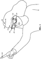
- FIG. 1 shows an example head mounted display 100 configured to detect finger gestures and/or other objects.
- the example head mounted display 100 includes a first stereo camera 102 configured to capture a first image of finger 104 and a second stereo camera 106 configured to capture a second image of finger 104.
- the first stereo camera 102 has a distance 108 from the second stereo camera 106.
- the head mounted display 100 may also include a see-through display 110 configured to display augmented reality images to the user 112.
- augmented reality images may include interactive targets that may be activated or otherwise engaged by finger gestures from user 112.
- FIG. 2 shows an example method 200 of finger detection using stereo images.
- Method 200 may be used for finger detection by head mounted display 100 or by any device that receives images from and/or includes a first stereo camera and a second stereo camera. Further, method 200 may be used to detect virtually any type of object. Finger detection is provided as a non-limiting example.
- method 200 includes receiving a first image taken by a first stereo camera, and at 204, method 200 includes receiving a second image taken by a second stereo camera.
- the first stereo camera 102 is a left stereo camera
- the second stereo camera 106 is a right stereo camera.
- FIG. 3A shows an example of a left image 300 and a right image 302 respectively captured by first stereo camera 102 and second stereo camera 106 of FIG. 1 .
- Objects in the relative location of the first image and second image depict a same object locus when the objects are at an assumed distance and the first and second images are offset by an amount derived from this distance.
- the assumed distance is the approximate length of the user's reach and the target object is the user's finger 104.
- the left image 300 and the right image 302 may be offset by offset distance 304 so as to depict finger 104 in the same region in offset left image 300' and offset right image 302'.
- FIG. 3B shows the offset left image 300' and offset right image 302' being cropped by an offset distance 304 that allows the same object locus to be depicted in the same region of the offset images.
- a left portion of offset left image 300' is cropped, while a right portion of offset right image 302' is cropped.
- finger 104 is depicted in the same region 306 in the offset left and right images 300' and 302'.
- the background tree 308 is not at or near the assumed distance, the background tree 308 is not depicted in the same region in the offset left and right images.
- the disparity between objects in the left image and the right image is inversely related to the distance between the stereo cameras and the target object. For example, objects that are relatively near to the stereo cameras will appear to have a greater disparity between depicted objects than objects that are relatively far from the stereo cameras.
- region 306 may be a corresponding pixel in the offset left and right images 300' and 302'.
- region 306 may be the same pixel (e.g., pixel N x , N y ) in the left image and the right image after cropping the images by the offset distance 304.
- method 200 of FIG. 2 includes offsetting the first image relative to the second image by an offset distance selected such that each corresponding pixel of offset first and second images depict a same object locus if the object locus is at an assumed distance from the first and second stereo cameras.
- the assume distance is the approximate length of the user's reach when performing finger gestures.
- the assumed distance may be the apparent distance to such an augmented reality interactive target.
- method 200 includes locating a target object in the offset first and second images.
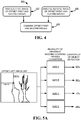
- FIG. 4 shows an example method 400 of locating a target object in the offset first and second images. Locating a target object may include several operations in which the offset first and second images are analyzed independently. Therefore, at 402, method 400 includes analyzing the first image of the offset first and second images, and at 404, method 400 includes analyzing the second image of the offset first and second images.
- Analysis of the offset first and second images may include application of a plurality of different machine-learning trained classifiers trained for object detection using training objects (i.e., a plurality of different fingers).
- the machine-learning trained classifier may be configured to analyze an image and output a heat map that includes a relative confidence of object detection for each pixel correlated to the corresponding pixel in the analyzed image.
- a high confidence results.
- objects that are different from the training object in shape, size, and orientation may result in low confidences.
- the same image may be input to each of a plurality of different machine-learning trained classifiers trained for detecting an object of a different size than other of the plurality of machine-learning trained classifiers.
- FIG. 5A shows offset left image 300' input into a plurality of different machine-learning trained classifiers trained for detecting various finger sizes (e.g., sizes A-D).
- FIG. 5A also shows the plurality of different machine learning trained classifiers each outputting a confidence of object detection (e.g., 82%, 96%, 72%, and 69%) for the region of offset left image 300' that is 34% from the left edge of the image in the x-direction and 36% from the top edge of the image in the y direction.
- a confidence of object detection e.g. 82%, 96%, 72%, and 69%
- the highest confidence of object detection for the region at 34%, 36% is calculated by the machine-learning trained classifier trained to detect fingers of size B.
- a confidence may be output for each region of the analyzed image.
- a heat map may record the highest confidence for each pixel or region of the analyzed image.
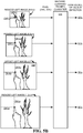
- a source image may be scaled to a plurality of different resolutions, and the same machine-learning trained classifier may be applied to each image in the scaled set of offset first and second images.
- FIG. 5B shows an example of resizing the offset left image 300' (shown as resolution J in offset left image (J)) to produce three other corresponding images of varying resolution (resized left image (1.2xJ), resized left image (0.8xJ), and resized left image (0.6xJ)). All four images may be analyzed by the same machine-learning trained classifier 500. As shown, the highest confidence of object detection for the region at 34%, 36% is calculated based on analysis of left image (1.2xJ). Such a confidence may be output for each region of the analyzed image. For example, a heat map may record the highest confidence for each pixel or region of the analyzed images.
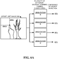
- the same image may be input to each of a plurality of different machine-learning trained classifiers trained for detecting an object of a different orientation than other of the plurality of machine-learning trained classifiers.
- FIG. 6A shows offset left image 300' input into a plurality of different machine-learning trained classifiers trained for detecting fingers having different orientations.
- the highest confidence of object detection for the region at 34%, 36% is calculated by the machine-learning trained classifier trained to detect fingers having orientation C.
- Such a confidence may be output for each region of the analyzed image.
- a heat map may record the highest confidence for each pixel or region of the analyzed image.
- a sister heat map may be generated to identify, for each pixel or region, which orientation resulted in the highest confidence for that pixel or region.
- a source image may be rotated to a plurality of different orientations, and the same machine-learning trained classifier may be applied to each member in the rotated set of offset first and second images.
- FIG. 6B shows an original orientation for the offset left image, and two rotated orientations (e.g., rotated orientation (+35°) and rotated orientation (-35°)) being input into machine-learning trained classifier 502.
- the highest confidence of object detection for an analyzed region is calculated based on analysis of the original image.
- Such a confidence may be output for each region of the analyzed image.
- a heat map may record the highest confidence for each pixel or region of the analyzed images.
- One or more of the above described analysis may be performed to estimate a likelihood of object detection for each region of an analyzed image.
- two or more different corresponding confidences may be produced.
- the highest confidence for that pixel or region is correlated to that pixel or region. For example, using the examples discussed above, the confidence of 96% corresponding to the machine-learning trained classifier trained to detect objects of size B (of FIG. 5A ) would be correlated to the pixel at 34%, 36%.
- Correlated confidences may be used in combination with adjacent correlated confidences to smooth correlated confidences for each of the offset first and second images. For example, the confidence value of 96% for the pixel at 34%, 36% of FIG. 5B may be smoothed with the correlated confidences of the eight nearest neighbor pixels around the pixel at 34%, 36% using a Gaussian smoothing operation.
- Smoothing correlated confidences may also occur across different resolutions. For example, the correlated confidence from the offset left image (J) of 78% may be smoothed with the resized left image (0.8xJ) correlated confidence of 64% and the resized left image (1.2xJ) correlated confidence of 92% using a Gaussian smoothing operation. Smoothing correlated confidences across resolutions may include using all eighteen nearest neighbor pixels in the smaller and larger resolution images.
- method 400 includes combining offset first and second images. For example the correlated confidence of object detection in the first image may be combined with the correlated confidence of object detection in the second image to yield a combined confidence of object detection for each corresponding pixel or region in the offset first and second images.
- FIG. 7 shows an example method 700 of combining correlated confidences of the first image and the second image.
- method 700 includes combining the correlated confidence in the offset first image and the correlated confidence in the offset second image (e.g., offset left image 300' and offset right image 302' of FIG. 3B ).
- combining may include averaging the correlated confidence of object detection in the offset first image and the correlated confidence of object detection in the offset second image.
- other combining techniques may also be used without departing from the scope of this disclosure.
- method 700 includes determining if a given pixel has a combined confidence that is less than a combined confidence of any neighboring pixels. If the combined confidence is less than the combined confidence of one or more neighboring pixels, the combined confidence may be set to zero, as shown at 706 in method 700. However, if the combined confidence is greater than the combined confidence of all neighboring pixels, the combined confidence may be used in further analysis.
- method 700 includes determining if the combined confidence is less than a threshold confidence. As shown at 710, if the combined confidence is less than the threshold confidence, method 700 includes discarding combined confidences that are less than the threshold. For example, if the threshold confidence is 75%, the correlated confidence in the first image is 80%, and the correlated confidence in the second image is 65%, the averaged combined confidence of 72.5% does not meet the threshold confidence and may be discarded. However, if the combined confidence is greater than the threshold confidence, the combined confidence may be used for further analysis.
- method 700 includes determining if the difference between correlated confidences of object detection in the first and second images is greater than a threshold.
- a threshold may describe the maximum allowable disparity between the correlated confidence in the first image and the correlated confidence in the second image.
- method 700 includes discarding the combined confidence.
- the threshold may be 25%
- the correlated confidence in the first image may be 99%
- the correlated confidence in the second image may be 70%. Therefore, the disparity between correlated confidences of 29% is greater than the threshold and the combined confidence may be discarded.
- the combined confidence may be used for further analysis.
- method 700 includes using the combined confidence to identify candidate regions in one or both of the first image or the second image that may include a target object.
- a finger location may be recognized based upon the confidence of finger detection from the image compared to the combined confidence heat map.
- the methods and processes described herein may be tied to a computing system of one or more computing devices.
- such methods and processes may be implemented as a computer-application program or service, an application-programming interface (API), a library, and/or other computer-program product.
- API application-programming interface
- FIG. 8 schematically shows a non-limiting embodiment of a computing system 800 that can enact one or more of the methods and processes described above.
- Computing system 800 is shown in simplified form.
- Computing system 800 may take the form of one or more personal computers, server computers, tablet computers, home-entertainment computers, network computing devices, gaming devices, mobile computing devices, mobile communication devices (e.g., smart phone), and/or other computing devices.
- Computing system 800 includes a logic machine 802 and a storage machine 804, and a display subsystem 806 (e.g., see-through display 110 of FIG. 1 ).
- Computing system 800 may optionally include an input subsystem 808, communication subsystem 810, and/or other components not shown in FIG. 8 .
- Logic machine 802 includes one or more physical devices configured to execute instructions.
- the logic machine may be configured to execute instructions that are part of one or more applications, services, programs, routines, libraries, objects, components, data structures, or other logical constructs.
- Such instructions may be implemented to perform a task, implement a data type, transform the state of one or more components, achieve a technical effect, or otherwise arrive at a desired result.
- the logic machine may include one or more processors configured to execute software instructions. Additionally or alternatively, the logic machine may include one or more hardware or firmware logic machines configured to execute hardware or firmware instructions. Processors of the logic machine may be single-core or multi-core, and the instructions executed thereon may be configured for sequential, parallel, and/or distributed processing. Individual components of the logic machine optionally may be distributed among two or more separate devices, which may be remotely located and/or configured for coordinated processing. Aspects of the logic machine may be virtualized and executed by remotely accessible, networked computing devices configured in a cloud-computing configuration.
- Storage machine 804 includes one or more physical devices configured to hold instructions executable by the logic machine to implement the methods and processes described herein. When such methods and processes are implemented, the state of storage machine 804 may be transformed-e.g., to hold different data.
- Storage machine 804 may include removable and/or built-in devices.
- Storage machine 804 may include optical memory (e.g., CD, DVD, HD-DVD, Blu-Ray Disc, etc.), semiconductor memory (e.g., RAM, EPROM, EEPROM, etc.), and/or magnetic memory (e.g., hard-disk drive, floppy-disk drive, tape drive, MRAM, etc.), among others.
- Storage machine 804 may include volatile, nonvolatile, dynamic, static, read/write, read-only, random-access, sequential-access, location-addressable, file-addressable, and/or content-addressable devices.
- storage machine 804 includes one or more physical devices.
- aspects of the instructions described herein alternatively may be propagated by a communication medium (e.g., an electromagnetic signal, an optical signal, etc.) that is not held by a physical device for a finite duration.
- a communication medium e.g., an electromagnetic signal, an optical signal, etc.
- logic machine 802 and storage machine 804 may be integrated together into one or more hardware-logic components.
- Such hardware-logic components may include field-programmable gate arrays (FPGAs), program- and application-specific integrated circuits (PASIC / ASICs), program- and application-specific standard products (PSSP / ASSPs), system-on-a-chip (SOC), and complex programmable logic devices (CPLDs), for example.
- FPGAs field-programmable gate arrays
- PASIC / ASICs program- and application-specific integrated circuits
- PSSP / ASSPs program- and application-specific standard products
- SOC system-on-a-chip
- CPLDs complex programmable logic devices
- display subsystem 806 may be used to present a visual representation of data held by storage machine 804.
- This visual representation may take the form of a graphical user interface (GUI).
- GUI graphical user interface
- Display subsystem 806 may include one or more display devices utilizing virtually any type of virtual or augmented reality display technology. Such display devices may be combined with logic machine 802 and/or storage machine 804 in a shared enclosure, or such display devices may be peripheral display devices.
- input subsystem 808 may comprise or interface with one or more user-input devices.
- the input subsystem may comprise or interface with selected natural user input (NUI) componentry.
- NUI natural user input
- Such componentry may be integrated or peripheral, and the transduction and/or processing of input actions may be handled on- or off-board.
- NUI componentry may include a microphone for speech and/or voice recognition; an infrared, color, stereoscopic, and/or depth camera for machine vision and/or gesture recognition; a head tracker, eye tracker, accelerometer, and/or gyroscope for motion detection and/or intent recognition; as well as electric-field sensing componentry for assessing brain activity.
- communication subsystem 810 may be configured to communicatively couple computing system 800 with one or more other computing devices.
- Communication subsystem 810 may include wired and/or wireless communication devices compatible with one or more different communication protocols.
- the communication subsystem may be configured for communication via a wireless telephone network, or a wired or wireless local- or wide-area network.
- the communication subsystem may allow computing system 800 to send and/or receive messages to and/or from other devices via a network such as the Internet.
Landscapes
- Engineering & Computer Science (AREA)
- Theoretical Computer Science (AREA)
- General Engineering & Computer Science (AREA)
- Physics & Mathematics (AREA)
- General Physics & Mathematics (AREA)
- Computer Vision & Pattern Recognition (AREA)
- Human Computer Interaction (AREA)
- Data Mining & Analysis (AREA)
- Artificial Intelligence (AREA)
- Evolutionary Computation (AREA)
- Multimedia (AREA)
- Life Sciences & Earth Sciences (AREA)
- Bioinformatics & Cheminformatics (AREA)
- Bioinformatics & Computational Biology (AREA)
- Evolutionary Biology (AREA)
- Software Systems (AREA)
- Medical Informatics (AREA)
- General Health & Medical Sciences (AREA)
- Databases & Information Systems (AREA)
- Computing Systems (AREA)
- Health & Medical Sciences (AREA)
- Image Analysis (AREA)
- User Interface Of Digital Computer (AREA)
Claims (8)
- Verfahren zum Erkennen eines Zielobjekts, wobei das Verfahren umfasst:Empfangen (202) eines linken Bildes (300), das von einer Stereokamera (102, 106) aufgenommen wurde; undEmpfangen (204) eines rechten Bildes (302), das von der Stereokamera aufgenommen wurde; gekennzeichnet durchVersetzen (206) des linken Bildes und des rechten Bildes relativ zueinander um eine Versatzdisparität, um versetzte linke und rechte Bilder (300', 302') zu erzeugen, wobei die Versatzdisparität aus einer angenommenen Entfernung zwischen der Stereokamera und dem Zielobjekt abgeleitet wird, um die Disparität in den versetzten linken und rechten Bildern zwischen Darstellungen eines Objekts, das in der angenommenen Entfernung von der Stereokamera erscheint, zu entfernen; undLokalisieren (208) des Zielobjekts (104) in den versetzten linken und rechten Bildern, wobei das Lokalisieren des Zielobjekts umfasst:Anwenden (402/404) eines maschinenlerngeschulten Klassifizierers (500; 502) auf das versetzte linke Bild (300'), um eine erste Sicherheit der Objekterkennung für jeden Pixel in dem versetzten linken Bild zu bestimmen;Anwenden (404/402) des maschinenlerngeschulten Klassifizierers (500; 502) auf das versetzte rechte Bild (302'), um eine zweite Sicherheit der Objekterkennung für jeden Pixel in dem versetzten rechten Bild zu bestimmen;Kombinieren (406; 700) der korrelierten Sicherheiten der Objekterkennung in den versetzten linken und rechten Bildern, um eine kombinierte Sicherheit der Objekterkennung für jeden entsprechenden Pixel in den versetzten ersten und zweiten Bildern zu erhalten; undBestimmen (716) eines Kandidatenbereichs in einem oder beiden der versetzten linken und rechten Bilder, der das Zielobjekt beinhaltet, wobei die Pixel in dem Kandidatenbereich die folgenden Bedingungen erfüllen:die kombinierte Sicherheit ist nicht kleiner als eine Schwellenwertsicherheit und die Differenz zwischen korrelierten Sicherheiten des ersten und des zweiten Bildes ist nicht größer als ein Schwellenwert.
- Verfahren nach Anspruch 1, wobei das Lokalisieren (208) Anwenden einer Vielzahl unterschiedlicher maschinenlerngeschulter Klassifizierer auf die versetzten linken und rechten Bilder (300', 302') beinhaltet, wobei jeder der Vielzahl unterschiedlicher maschinenlerngeschulter Klassifizierer die Sicherheit der Objekterkennung für jeden Pixel in den versetzten linken und rechten Bildern bestimmt, und wobei eine höchste Sicherheit für jeden Pixel mit diesem Pixel korreliert;wobei i) jeder der Vielzahl unterschiedlicher maschinenlerngeschulter Klassifizierer (AUSRICHTUNG A-D) für Erkennen eines Objekts in einer Ausrichtung geschult ist, die sich von der anderer der Vielzahl unterschiedlicher maschinenlerngeschulter Klassifizierer unterscheidet; und/oderwobei ii) jeder der Vielzahl unterschiedlicher maschinenlerngeschulter Klassifizierer (GRÖSSE A-D) für Erkennen eines Objekts mit einer unterschiedlichen Größe als andere der Vielzahl unterschiedlicher maschinenlerngeschulter Klassifizierer geschult ist.
- Verfahren nach Anspruch 2, weiter Verwendung korrelierter Sicherheiten benachbarter Pixel umfassend, um die korrelierten Sicherheiten für jedes der versetzten linken und rechten Bilder (300', 302') zu glätten.
- Verfahren nach Anspruch 1, wobei das Lokalisieren (208) Anwenden eines maschinenlerngeschulten Klassifizierers auf einen Satz von versetzten linken und rechten Bildern beinhaltet, wobei jedes versetzte linke und rechte Bild des Satzes auf eine unterschiedliche Auflösung skaliert ist.
- Verfahren nach Anspruch 4, weiter Korrelieren der Sicherheit der Objekterkennung mit jedem Bereich der versetzten linken und rechten Bilder umfassend, wobei die Sicherheit, die aus den skalierten versetzten linken und rechten Bilder der Auflösung abgeleitet wird, eine höchste Sicherheit der Objekterkennung für diesen Bereich aufweist.
- Verfahren nach Anspruch 5, weiter Glätten der korrelierten Sicherheit über unterschiedliche Auflösungen umfassend.
- Verfahren nach Anspruch 1, wobei Lokalisieren Anwenden eines maschinenlerngeschulten Klassifizierers (502) auf einen Satz versetzter linker und rechter Bilder (300', 302') beinhaltet, wobei jedes Element des Satzes in eine unterschiedliche Ausrichtung dreht.
- Verfahren nach Anspruch 1, wobei die Pixel in dem Kandidatenbereich weiter die Bedingung erfüllen, dass die kombinierte Sicherheit nicht kleiner als eine benachbarte kombinierte Sicherheit ist.
Applications Claiming Priority (2)
| Application Number | Priority Date | Filing Date | Title |
|---|---|---|---|
| US13/926,882 US9934451B2 (en) | 2013-06-25 | 2013-06-25 | Stereoscopic object detection leveraging assumed distance |
| PCT/US2014/043545 WO2014209817A1 (en) | 2013-06-25 | 2014-06-23 | Stereoscopic object detection leveraging assumed distance |
Publications (2)
| Publication Number | Publication Date |
|---|---|
| EP3014522A1 EP3014522A1 (de) | 2016-05-04 |
| EP3014522B1 true EP3014522B1 (de) | 2019-12-11 |
Family
ID=51263472
Family Applications (1)
| Application Number | Title | Priority Date | Filing Date |
|---|---|---|---|
| EP14747170.0A Active EP3014522B1 (de) | 2013-06-25 | 2014-06-23 | Stereoskopische objekterkennung unter nutzung des geschätzten abstandes |
Country Status (4)
| Country | Link |
|---|---|
| US (2) | US9934451B2 (de) |
| EP (1) | EP3014522B1 (de) |
| CN (1) | CN105378754B (de) |
| WO (1) | WO2014209817A1 (de) |
Families Citing this family (11)
| Publication number | Priority date | Publication date | Assignee | Title |
|---|---|---|---|---|
| WO2013052025A1 (en) * | 2011-10-03 | 2013-04-11 | Hewlett-Packard Development Company, L.P. | Region selection for counterfeit determinations |
| US10442025B2 (en) * | 2014-10-22 | 2019-10-15 | Illinois Tool Works Inc. | Virtual reality controlled mobile robot |
| JP2016115965A (ja) * | 2014-12-11 | 2016-06-23 | ソニー株式会社 | 医療用眼鏡型表示装、情報処理装置及び情報処理方法 |
| JP6646361B2 (ja) * | 2015-04-27 | 2020-02-14 | ソニーセミコンダクタソリューションズ株式会社 | 画像処理装置、撮像装置、画像処理方法およびプログラム |
| WO2017104272A1 (ja) * | 2015-12-18 | 2017-06-22 | ソニー株式会社 | 情報処理装置、情報処理方法、及びプログラム |
| US20190066385A1 (en) * | 2017-08-31 | 2019-02-28 | Canon Kabushiki Kaisha | Image processing apparatus, image processing method, and non-transitory computer-readable storage medium |
| US10799183B2 (en) * | 2018-11-07 | 2020-10-13 | General Electric Company | Methods and systems for whole body imaging |
| FR3100357B1 (fr) * | 2019-08-27 | 2021-09-17 | Thales Sa | Procédé d'aide à la détection d'éléments, dispositif et plateforme associés |
| EP3901817A1 (de) * | 2020-04-22 | 2021-10-27 | Continental Automotive GmbH | Verfahren und system zur schlüsselpunkterkennung basierend auf neuronalen netzen |
| US20250078238A1 (en) * | 2023-08-31 | 2025-03-06 | Exfo Inc. | Enhanced optical fiber inspection using image segmentation |
| US20250199606A1 (en) * | 2023-12-19 | 2025-06-19 | Apple Inc. | Screenless Object Selection with Head Pose and Hand Gestures |
Family Cites Families (29)
| Publication number | Priority date | Publication date | Assignee | Title |
|---|---|---|---|---|
| JP3192875B2 (ja) * | 1994-06-30 | 2001-07-30 | キヤノン株式会社 | 画像合成方法および画像合成装置 |
| US6426745B1 (en) | 1997-04-28 | 2002-07-30 | Computer Associates Think, Inc. | Manipulating graphic objects in 3D scenes |
| JP3707259B2 (ja) * | 1998-09-10 | 2005-10-19 | コニカミノルタフォトイメージング株式会社 | 画像合成方法及びこの方法を用いた画像合成装置 |
| US7099510B2 (en) | 2000-11-29 | 2006-08-29 | Hewlett-Packard Development Company, L.P. | Method and system for object detection in digital images |
| US7248968B2 (en) | 2004-10-29 | 2007-07-24 | Deere & Company | Obstacle detection using stereo vision |
| US7512262B2 (en) | 2005-02-25 | 2009-03-31 | Microsoft Corporation | Stereo-based image processing |
| JP4177826B2 (ja) | 2005-03-23 | 2008-11-05 | 株式会社東芝 | 画像処理装置および画像処理方法 |
| JP4744918B2 (ja) | 2005-04-19 | 2011-08-10 | 富士フイルム株式会社 | 顔検出方法および装置並びにプログラム |
| JP2007066010A (ja) | 2005-08-31 | 2007-03-15 | Fujifilm Corp | 判別器学習方法および対象判別装置ならびにプログラム |
| US8094928B2 (en) | 2005-11-14 | 2012-01-10 | Microsoft Corporation | Stereo video for gaming |
| KR100745981B1 (ko) | 2006-01-13 | 2007-08-06 | 삼성전자주식회사 | 보상적 특징에 기반한 확장형 얼굴 인식 방법 및 장치 |
| JP4640825B2 (ja) | 2006-02-23 | 2011-03-02 | 富士フイルム株式会社 | 特定向き顔判定方法および装置並びにプログラム |
| KR100762670B1 (ko) | 2006-06-07 | 2007-10-01 | 삼성전자주식회사 | 스테레오 이미지로부터 디스패리티 맵을 생성하는 방법 및장치와 그를 위한 스테레오 매칭 방법 및 장치 |
| KR101311896B1 (ko) * | 2006-11-14 | 2013-10-14 | 삼성전자주식회사 | 입체 영상의 변위 조정방법 및 이를 적용한 입체 영상장치 |
| GB2477333B (en) | 2010-01-29 | 2014-12-03 | Sony Corp | A method and apparatus for creating a stereoscopic image |
| US8861842B2 (en) | 2010-02-05 | 2014-10-14 | Sri International | Method and apparatus for real-time pedestrian detection for urban driving |
| US20150309316A1 (en) * | 2011-04-06 | 2015-10-29 | Microsoft Technology Licensing, Llc | Ar glasses with predictive control of external device based on event input |
| WO2011121818A1 (ja) * | 2010-03-30 | 2011-10-06 | 富士フイルム株式会社 | 複眼撮像装置、その視差調整方法及びプログラム |
| US8509526B2 (en) | 2010-04-13 | 2013-08-13 | International Business Machines Corporation | Detection of objects in digital images |
| JP2011243025A (ja) | 2010-05-19 | 2011-12-01 | Fujifilm Corp | 対象画像の追尾装置およびその動作制御方法 |
| EP2389004B1 (de) * | 2010-05-20 | 2013-07-24 | Sony Computer Entertainment Europe Ltd. | 3D-Kamera und Abbildungsverfahren |
| US20110316972A1 (en) * | 2010-06-29 | 2011-12-29 | Broadcom Corporation | Displaying graphics with three dimensional video |
| US20120113223A1 (en) | 2010-11-05 | 2012-05-10 | Microsoft Corporation | User Interaction in Augmented Reality |
| US9380285B2 (en) * | 2010-12-20 | 2016-06-28 | Samsung Display Co., Ltd. | Stereo image processing method, stereo image processing device and display device |
| US8811663B2 (en) | 2011-01-05 | 2014-08-19 | International Business Machines Corporation | Object detection in crowded scenes |
| US8565482B2 (en) | 2011-02-28 | 2013-10-22 | Seiko Epson Corporation | Local difference pattern based local background modeling for object detection |
| US8897491B2 (en) | 2011-06-06 | 2014-11-25 | Microsoft Corporation | System for finger recognition and tracking |
| WO2013034294A1 (de) | 2011-09-08 | 2013-03-14 | Daimler Ag | Bedienvorrichtung für ein kraftfahrzeug und verfahren zum bedienen der bedienvorrichtung für ein kraftfahrzeug |
| US8995772B2 (en) | 2012-11-09 | 2015-03-31 | Microsoft Technology Licensing, Llc | Real-time face detection using pixel pairs |
-
2013
- 2013-06-25 US US13/926,882 patent/US9934451B2/en active Active
-
2014
- 2014-06-23 WO PCT/US2014/043545 patent/WO2014209817A1/en not_active Ceased
- 2014-06-23 CN CN201480036556.4A patent/CN105378754B/zh active Active
- 2014-06-23 EP EP14747170.0A patent/EP3014522B1/de active Active
-
2018
- 2018-03-06 US US15/913,118 patent/US10592778B2/en active Active
Non-Patent Citations (1)
| Title |
|---|
| None * |
Also Published As
| Publication number | Publication date |
|---|---|
| US20180197047A1 (en) | 2018-07-12 |
| WO2014209817A1 (en) | 2014-12-31 |
| CN105378754A (zh) | 2016-03-02 |
| US10592778B2 (en) | 2020-03-17 |
| US20140376770A1 (en) | 2014-12-25 |
| EP3014522A1 (de) | 2016-05-04 |
| US9934451B2 (en) | 2018-04-03 |
| CN105378754B (zh) | 2019-08-02 |
Similar Documents
| Publication | Publication Date | Title |
|---|---|---|
| US10592778B2 (en) | Stereoscopic object detection leveraging expected object distance | |
| EP2912659B1 (de) | Erweiterung der spracherkennung mit tiefenbildgebung | |
| EP3268897B1 (de) | Unterscheidung von vorder- und hintergrund mit infrarotbildgebung | |
| US9807342B2 (en) | Collaborative presentation system | |
| US9251427B1 (en) | False face representation identification | |
| US9454699B2 (en) | Handling glare in eye tracking | |
| US20170085790A1 (en) | High-resolution imaging of regions of interest | |
| US20140357369A1 (en) | Group inputs via image sensor system | |
| JP6731097B2 (ja) | 人体行動分析方法、人体行動分析装置、機器及びコンピュータ可読記憶媒体 | |
| US9087402B2 (en) | Augmenting images with higher resolution data | |
| US9972091B2 (en) | System and method for detecting object from depth image | |
| US11106949B2 (en) | Action classification based on manipulated object movement | |
| US10649536B2 (en) | Determination of hand dimensions for hand and gesture recognition with a computing interface | |
| US9165180B2 (en) | Illumination sensitive face recognition | |
| WO2017165332A1 (en) | 2d video analysis for 3d modeling | |
| CN108701376A (zh) | 三维图像的基于识别的对象分割 | |
| WO2014197283A1 (en) | Edge preserving depth filtering | |
| EP3035242B1 (de) | Verfahren und elektronische vorrichtung zur objektverfolgung in einer lichtfelderfassung | |
| US20140098246A1 (en) | Method, Apparatus and Computer-Readable Recording Medium for Refocusing Photographed Image | |
| EP3286689B1 (de) | Klassifizierung von mehrdeutigen bilddaten | |
| US20180096195A1 (en) | Probabilistic face detection | |
| WO2023007730A1 (ja) | 情報処理システム、情報処理装置、情報処理方法、及び記録媒体 |
Legal Events
| Date | Code | Title | Description |
|---|---|---|---|
| PUAI | Public reference made under article 153(3) epc to a published international application that has entered the european phase |
Free format text: ORIGINAL CODE: 0009012 |
|
| 17P | Request for examination filed |
Effective date: 20151130 |
|
| AK | Designated contracting states |
Kind code of ref document: A1 Designated state(s): AL AT BE BG CH CY CZ DE DK EE ES FI FR GB GR HR HU IE IS IT LI LT LU LV MC MK MT NL NO PL PT RO RS SE SI SK SM TR |
|
| AX | Request for extension of the european patent |
Extension state: BA ME |
|
| DAX | Request for extension of the european patent (deleted) | ||
| STAA | Information on the status of an ep patent application or granted ep patent |
Free format text: STATUS: EXAMINATION IS IN PROGRESS |
|
| 17Q | First examination report despatched |
Effective date: 20180216 |
|
| GRAP | Despatch of communication of intention to grant a patent |
Free format text: ORIGINAL CODE: EPIDOSNIGR1 |
|
| STAA | Information on the status of an ep patent application or granted ep patent |
Free format text: STATUS: GRANT OF PATENT IS INTENDED |
|
| INTG | Intention to grant announced |
Effective date: 20190705 |
|
| GRAS | Grant fee paid |
Free format text: ORIGINAL CODE: EPIDOSNIGR3 |
|
| GRAA | (expected) grant |
Free format text: ORIGINAL CODE: 0009210 |
|
| STAA | Information on the status of an ep patent application or granted ep patent |
Free format text: STATUS: THE PATENT HAS BEEN GRANTED |
|
| AK | Designated contracting states |
Kind code of ref document: B1 Designated state(s): AL AT BE BG CH CY CZ DE DK EE ES FI FR GB GR HR HU IE IS IT LI LT LU LV MC MK MT NL NO PL PT RO RS SE SI SK SM TR |
|
| REG | Reference to a national code |
Ref country code: GB Ref legal event code: FG4D |
|
| REG | Reference to a national code |
Ref country code: CH Ref legal event code: EP |
|
| REG | Reference to a national code |
Ref country code: AT Ref legal event code: REF Ref document number: 1212912 Country of ref document: AT Kind code of ref document: T Effective date: 20191215 |
|
| REG | Reference to a national code |
Ref country code: DE Ref legal event code: R096 Ref document number: 602014058240 Country of ref document: DE |
|
| REG | Reference to a national code |
Ref country code: IE Ref legal event code: FG4D |
|
| REG | Reference to a national code |
Ref country code: NL Ref legal event code: MP Effective date: 20191211 |
|
| REG | Reference to a national code |
Ref country code: LT Ref legal event code: MG4D |
|
| PG25 | Lapsed in a contracting state [announced via postgrant information from national office to epo] |
Ref country code: LV Free format text: LAPSE BECAUSE OF FAILURE TO SUBMIT A TRANSLATION OF THE DESCRIPTION OR TO PAY THE FEE WITHIN THE PRESCRIBED TIME-LIMIT Effective date: 20191211 Ref country code: SE Free format text: LAPSE BECAUSE OF FAILURE TO SUBMIT A TRANSLATION OF THE DESCRIPTION OR TO PAY THE FEE WITHIN THE PRESCRIBED TIME-LIMIT Effective date: 20191211 Ref country code: LT Free format text: LAPSE BECAUSE OF FAILURE TO SUBMIT A TRANSLATION OF THE DESCRIPTION OR TO PAY THE FEE WITHIN THE PRESCRIBED TIME-LIMIT Effective date: 20191211 Ref country code: NO Free format text: LAPSE BECAUSE OF FAILURE TO SUBMIT A TRANSLATION OF THE DESCRIPTION OR TO PAY THE FEE WITHIN THE PRESCRIBED TIME-LIMIT Effective date: 20200311 Ref country code: GR Free format text: LAPSE BECAUSE OF FAILURE TO SUBMIT A TRANSLATION OF THE DESCRIPTION OR TO PAY THE FEE WITHIN THE PRESCRIBED TIME-LIMIT Effective date: 20200312 Ref country code: FI Free format text: LAPSE BECAUSE OF FAILURE TO SUBMIT A TRANSLATION OF THE DESCRIPTION OR TO PAY THE FEE WITHIN THE PRESCRIBED TIME-LIMIT Effective date: 20191211 Ref country code: BG Free format text: LAPSE BECAUSE OF FAILURE TO SUBMIT A TRANSLATION OF THE DESCRIPTION OR TO PAY THE FEE WITHIN THE PRESCRIBED TIME-LIMIT Effective date: 20200311 |
|
| PG25 | Lapsed in a contracting state [announced via postgrant information from national office to epo] |
Ref country code: RS Free format text: LAPSE BECAUSE OF FAILURE TO SUBMIT A TRANSLATION OF THE DESCRIPTION OR TO PAY THE FEE WITHIN THE PRESCRIBED TIME-LIMIT Effective date: 20191211 Ref country code: HR Free format text: LAPSE BECAUSE OF FAILURE TO SUBMIT A TRANSLATION OF THE DESCRIPTION OR TO PAY THE FEE WITHIN THE PRESCRIBED TIME-LIMIT Effective date: 20191211 |
|
| PG25 | Lapsed in a contracting state [announced via postgrant information from national office to epo] |
Ref country code: AL Free format text: LAPSE BECAUSE OF FAILURE TO SUBMIT A TRANSLATION OF THE DESCRIPTION OR TO PAY THE FEE WITHIN THE PRESCRIBED TIME-LIMIT Effective date: 20191211 |
|
| PG25 | Lapsed in a contracting state [announced via postgrant information from national office to epo] |
Ref country code: RO Free format text: LAPSE BECAUSE OF FAILURE TO SUBMIT A TRANSLATION OF THE DESCRIPTION OR TO PAY THE FEE WITHIN THE PRESCRIBED TIME-LIMIT Effective date: 20191211 Ref country code: EE Free format text: LAPSE BECAUSE OF FAILURE TO SUBMIT A TRANSLATION OF THE DESCRIPTION OR TO PAY THE FEE WITHIN THE PRESCRIBED TIME-LIMIT Effective date: 20191211 Ref country code: PT Free format text: LAPSE BECAUSE OF FAILURE TO SUBMIT A TRANSLATION OF THE DESCRIPTION OR TO PAY THE FEE WITHIN THE PRESCRIBED TIME-LIMIT Effective date: 20200506 Ref country code: CZ Free format text: LAPSE BECAUSE OF FAILURE TO SUBMIT A TRANSLATION OF THE DESCRIPTION OR TO PAY THE FEE WITHIN THE PRESCRIBED TIME-LIMIT Effective date: 20191211 Ref country code: NL Free format text: LAPSE BECAUSE OF FAILURE TO SUBMIT A TRANSLATION OF THE DESCRIPTION OR TO PAY THE FEE WITHIN THE PRESCRIBED TIME-LIMIT Effective date: 20191211 Ref country code: ES Free format text: LAPSE BECAUSE OF FAILURE TO SUBMIT A TRANSLATION OF THE DESCRIPTION OR TO PAY THE FEE WITHIN THE PRESCRIBED TIME-LIMIT Effective date: 20191211 |
|
| PG25 | Lapsed in a contracting state [announced via postgrant information from national office to epo] |
Ref country code: SM Free format text: LAPSE BECAUSE OF FAILURE TO SUBMIT A TRANSLATION OF THE DESCRIPTION OR TO PAY THE FEE WITHIN THE PRESCRIBED TIME-LIMIT Effective date: 20191211 Ref country code: SK Free format text: LAPSE BECAUSE OF FAILURE TO SUBMIT A TRANSLATION OF THE DESCRIPTION OR TO PAY THE FEE WITHIN THE PRESCRIBED TIME-LIMIT Effective date: 20191211 Ref country code: IS Free format text: LAPSE BECAUSE OF FAILURE TO SUBMIT A TRANSLATION OF THE DESCRIPTION OR TO PAY THE FEE WITHIN THE PRESCRIBED TIME-LIMIT Effective date: 20200411 |
|
| REG | Reference to a national code |
Ref country code: DE Ref legal event code: R097 Ref document number: 602014058240 Country of ref document: DE |
|
| REG | Reference to a national code |
Ref country code: AT Ref legal event code: MK05 Ref document number: 1212912 Country of ref document: AT Kind code of ref document: T Effective date: 20191211 |
|
| PLBE | No opposition filed within time limit |
Free format text: ORIGINAL CODE: 0009261 |
|
| STAA | Information on the status of an ep patent application or granted ep patent |
Free format text: STATUS: NO OPPOSITION FILED WITHIN TIME LIMIT |
|
| PG25 | Lapsed in a contracting state [announced via postgrant information from national office to epo] |
Ref country code: DK Free format text: LAPSE BECAUSE OF FAILURE TO SUBMIT A TRANSLATION OF THE DESCRIPTION OR TO PAY THE FEE WITHIN THE PRESCRIBED TIME-LIMIT Effective date: 20191211 |
|
| 26N | No opposition filed |
Effective date: 20200914 |
|
| PG25 | Lapsed in a contracting state [announced via postgrant information from national office to epo] |
Ref country code: SI Free format text: LAPSE BECAUSE OF FAILURE TO SUBMIT A TRANSLATION OF THE DESCRIPTION OR TO PAY THE FEE WITHIN THE PRESCRIBED TIME-LIMIT Effective date: 20191211 Ref country code: AT Free format text: LAPSE BECAUSE OF FAILURE TO SUBMIT A TRANSLATION OF THE DESCRIPTION OR TO PAY THE FEE WITHIN THE PRESCRIBED TIME-LIMIT Effective date: 20191211 |
|
| PG25 | Lapsed in a contracting state [announced via postgrant information from national office to epo] |
Ref country code: IT Free format text: LAPSE BECAUSE OF FAILURE TO SUBMIT A TRANSLATION OF THE DESCRIPTION OR TO PAY THE FEE WITHIN THE PRESCRIBED TIME-LIMIT Effective date: 20191211 Ref country code: MC Free format text: LAPSE BECAUSE OF FAILURE TO SUBMIT A TRANSLATION OF THE DESCRIPTION OR TO PAY THE FEE WITHIN THE PRESCRIBED TIME-LIMIT Effective date: 20191211 |
|
| REG | Reference to a national code |
Ref country code: CH Ref legal event code: PL |
|
| PG25 | Lapsed in a contracting state [announced via postgrant information from national office to epo] |
Ref country code: PL Free format text: LAPSE BECAUSE OF FAILURE TO SUBMIT A TRANSLATION OF THE DESCRIPTION OR TO PAY THE FEE WITHIN THE PRESCRIBED TIME-LIMIT Effective date: 20191211 |
|
| PG25 | Lapsed in a contracting state [announced via postgrant information from national office to epo] |
Ref country code: LU Free format text: LAPSE BECAUSE OF NON-PAYMENT OF DUE FEES Effective date: 20200623 |
|
| REG | Reference to a national code |
Ref country code: BE Ref legal event code: MM Effective date: 20200630 |
|
| PG25 | Lapsed in a contracting state [announced via postgrant information from national office to epo] |
Ref country code: CH Free format text: LAPSE BECAUSE OF NON-PAYMENT OF DUE FEES Effective date: 20200630 Ref country code: IE Free format text: LAPSE BECAUSE OF NON-PAYMENT OF DUE FEES Effective date: 20200623 Ref country code: LI Free format text: LAPSE BECAUSE OF NON-PAYMENT OF DUE FEES Effective date: 20200630 |
|
| PG25 | Lapsed in a contracting state [announced via postgrant information from national office to epo] |
Ref country code: BE Free format text: LAPSE BECAUSE OF NON-PAYMENT OF DUE FEES Effective date: 20200630 |
|
| REG | Reference to a national code |
Ref country code: DE Ref legal event code: R079 Ref document number: 602014058240 Country of ref document: DE Free format text: PREVIOUS MAIN CLASS: G06K0009000000 Ipc: G06V0010000000 |
|
| PG25 | Lapsed in a contracting state [announced via postgrant information from national office to epo] |
Ref country code: TR Free format text: LAPSE BECAUSE OF FAILURE TO SUBMIT A TRANSLATION OF THE DESCRIPTION OR TO PAY THE FEE WITHIN THE PRESCRIBED TIME-LIMIT Effective date: 20191211 Ref country code: MT Free format text: LAPSE BECAUSE OF FAILURE TO SUBMIT A TRANSLATION OF THE DESCRIPTION OR TO PAY THE FEE WITHIN THE PRESCRIBED TIME-LIMIT Effective date: 20191211 Ref country code: CY Free format text: LAPSE BECAUSE OF FAILURE TO SUBMIT A TRANSLATION OF THE DESCRIPTION OR TO PAY THE FEE WITHIN THE PRESCRIBED TIME-LIMIT Effective date: 20191211 |
|
| PG25 | Lapsed in a contracting state [announced via postgrant information from national office to epo] |
Ref country code: MK Free format text: LAPSE BECAUSE OF FAILURE TO SUBMIT A TRANSLATION OF THE DESCRIPTION OR TO PAY THE FEE WITHIN THE PRESCRIBED TIME-LIMIT Effective date: 20191211 |
|
| P01 | Opt-out of the competence of the unified patent court (upc) registered |
Effective date: 20230502 |
|
| PGFP | Annual fee paid to national office [announced via postgrant information from national office to epo] |
Ref country code: FR Payment date: 20240522 Year of fee payment: 11 |
|
| PGFP | Annual fee paid to national office [announced via postgrant information from national office to epo] |
Ref country code: DE Payment date: 20250520 Year of fee payment: 12 |
|
| PGFP | Annual fee paid to national office [announced via postgrant information from national office to epo] |
Ref country code: GB Payment date: 20250520 Year of fee payment: 12 |
|
| PG25 | Lapsed in a contracting state [announced via postgrant information from national office to epo] |
Ref country code: FR Free format text: LAPSE BECAUSE OF NON-PAYMENT OF DUE FEES Effective date: 20250630 |