US9934451B2 - Stereoscopic object detection leveraging assumed distance - Google Patents
Stereoscopic object detection leveraging assumed distance Download PDFInfo
- Publication number
- US9934451B2 US9934451B2 US13/926,882 US201313926882A US9934451B2 US 9934451 B2 US9934451 B2 US 9934451B2 US 201313926882 A US201313926882 A US 201313926882A US 9934451 B2 US9934451 B2 US 9934451B2
- Authority
- US
- United States
- Prior art keywords
- offset
- image
- confidence
- images
- machine
- Prior art date
- Legal status (The legal status is an assumption and is not a legal conclusion. Google has not performed a legal analysis and makes no representation as to the accuracy of the status listed.)
- Active, expires
Links
Images


Classifications
-
- G—PHYSICS
- G06—COMPUTING OR CALCULATING; COUNTING
- G06F—ELECTRIC DIGITAL DATA PROCESSING
- G06F3/00—Input arrangements for transferring data to be processed into a form capable of being handled by the computer; Output arrangements for transferring data from processing unit to output unit, e.g. interface arrangements
- G06F3/01—Input arrangements or combined input and output arrangements for interaction between user and computer
- G06F3/017—Gesture based interaction, e.g. based on a set of recognized hand gestures
-
- G06K9/6256—
-
- G—PHYSICS
- G06—COMPUTING OR CALCULATING; COUNTING
- G06F—ELECTRIC DIGITAL DATA PROCESSING
- G06F18/00—Pattern recognition
- G06F18/20—Analysing
- G06F18/21—Design or setup of recognition systems or techniques; Extraction of features in feature space; Blind source separation
- G06F18/214—Generating training patterns; Bootstrap methods, e.g. bagging or boosting
-
- G—PHYSICS
- G06—COMPUTING OR CALCULATING; COUNTING
- G06F—ELECTRIC DIGITAL DATA PROCESSING
- G06F18/00—Pattern recognition
- G06F18/20—Analysing
- G06F18/25—Fusion techniques
- G06F18/254—Fusion techniques of classification results, e.g. of results related to same input data
-
- G—PHYSICS
- G06—COMPUTING OR CALCULATING; COUNTING
- G06F—ELECTRIC DIGITAL DATA PROCESSING
- G06F3/00—Input arrangements for transferring data to be processed into a form capable of being handled by the computer; Output arrangements for transferring data from processing unit to output unit, e.g. interface arrangements
- G06F3/01—Input arrangements or combined input and output arrangements for interaction between user and computer
- G06F3/011—Arrangements for interaction with the human body, e.g. for user immersion in virtual reality
-
- G—PHYSICS
- G06—COMPUTING OR CALCULATING; COUNTING
- G06F—ELECTRIC DIGITAL DATA PROCESSING
- G06F3/00—Input arrangements for transferring data to be processed into a form capable of being handled by the computer; Output arrangements for transferring data from processing unit to output unit, e.g. interface arrangements
- G06F3/01—Input arrangements or combined input and output arrangements for interaction between user and computer
- G06F3/03—Arrangements for converting the position or the displacement of a member into a coded form
- G06F3/0304—Detection arrangements using opto-electronic means
-
- G06K9/00375—
-
- G06K9/00536—
-
- G06K9/6292—
-
- G—PHYSICS
- G06—COMPUTING OR CALCULATING; COUNTING
- G06T—IMAGE DATA PROCESSING OR GENERATION, IN GENERAL
- G06T7/00—Image analysis
- G06T7/70—Determining position or orientation of objects or cameras
- G06T7/73—Determining position or orientation of objects or cameras using feature-based methods
-
- G—PHYSICS
- G06—COMPUTING OR CALCULATING; COUNTING
- G06V—IMAGE OR VIDEO RECOGNITION OR UNDERSTANDING
- G06V10/00—Arrangements for image or video recognition or understanding
- G06V10/70—Arrangements for image or video recognition or understanding using pattern recognition or machine learning
- G06V10/77—Processing image or video features in feature spaces; using data integration or data reduction, e.g. principal component analysis [PCA] or independent component analysis [ICA] or self-organising maps [SOM]; Blind source separation
- G06V10/80—Fusion, i.e. combining data from various sources at the sensor level, preprocessing level, feature extraction level or classification level
- G06V10/809—Fusion, i.e. combining data from various sources at the sensor level, preprocessing level, feature extraction level or classification level of classification results, e.g. where the classifiers operate on the same input data
-
- G—PHYSICS
- G06—COMPUTING OR CALCULATING; COUNTING
- G06V—IMAGE OR VIDEO RECOGNITION OR UNDERSTANDING
- G06V40/00—Recognition of biometric, human-related or animal-related patterns in image or video data
- G06V40/10—Human or animal bodies, e.g. vehicle occupants or pedestrians; Body parts, e.g. hands
- G06V40/107—Static hand or arm
-
- G—PHYSICS
- G06—COMPUTING OR CALCULATING; COUNTING
- G06F—ELECTRIC DIGITAL DATA PROCESSING
- G06F2218/00—Aspects of pattern recognition specially adapted for signal processing
- G06F2218/12—Classification; Matching
Definitions
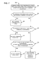
- FIG. 2 shows an example method of object detection.
- FIG. 5A shows a plurality of different machine-learning trained classifiers trained for detecting objects of different sizes in the offset first and second images.
- the disparity between objects in the left image and the right image is inversely related to the distance between the stereo cameras and the target object. For example, objects that are relatively near to the stereo cameras will appear to have a greater disparity between depicted objects than objects that are relatively far from the stereo cameras.
- a source image may be rotated to a plurality of different orientations, and the same machine-learning trained classifier may be applied to each member in the rotated set of offset first and second images.
- FIG. 6B shows an original orientation for the offset left image, and two rotated orientations (e.g., rotated orientation (+35°) and rotated orientation ( ⁇ 35°)) being input into machine-learning trained classifier 502 .
- the highest confidence of object detection for an analyzed region is calculated based on analysis of the original image.
- Such a confidence may be output for each region of the analyzed image.
- a heat map may record the highest confidence for each pixel or region of the analyzed images.
- Correlated confidences may be used in combination with adjacent correlated confidences to smooth correlated confidences for each of the offset first and second images. For example, the confidence value of 96% for the pixel at 34%, 36% of FIG. 5B may be smoothed with the correlated confidences of the eight nearest neighbor pixels around the pixel at 34%, 36% using a Gaussian smoothing operation.
- Smoothing correlated confidences may also occur across different resolutions. For example, the correlated confidence from the offset left image (J) of 78% may be smoothed with the resized left image (0.8xJ) correlated confidence of 64% and the resized left image (1.2xJ) correlated confidence of 92% using a Gaussian smoothing operation. Smoothing correlated confidences across resolutions may include using all eighteen nearest neighbor pixels in the smaller and larger resolution images.
- method 400 includes combining offset first and second images. For example the correlated confidence of object detection in the first image may be combined with the correlated confidence of object detection in the second image to yield a combined confidence of object detection for each corresponding pixel or region in the offset first and second images.
- the methods and processes described herein may be tied to a computing system of one or more computing devices.
- such methods and processes may be implemented as a computer-application program or service, an application-programming interface (API), a library, and/or other computer-program product.
- API application-programming interface
- FIG. 8 schematically shows a non-limiting embodiment of a computing system 800 that can enact one or more of the methods and processes described above.
- Computing system 800 is shown in simplified form.
- Computing system 800 may take the form of one or more personal computers, server computers, tablet computers, home-entertainment computers, network computing devices, gaming devices, mobile computing devices, mobile communication devices (e.g., smart phone), and/or other computing devices.
- Storage machine 804 includes one or more physical devices configured to hold instructions executable by the logic machine to implement the methods and processes described herein. When such methods and processes are implemented, the state of storage machine 804 may be transformed—e.g., to hold different data.
- Storage machine 804 may include removable and/or built-in devices.
- Storage machine 804 may include optical memory (e.g., CD, DVD, HD-DVD, Blu-Ray Disc, etc.), semiconductor memory (e.g., RAM, EPROM, EEPROM, etc.), and/or magnetic memory (e.g., hard-disk drive, floppy-disk drive, tape drive, MRAM, etc.), among others.
- Storage machine 804 may include volatile, nonvolatile, dynamic, static, read/write, read-only, random-access, sequential-access, location-addressable, file-addressable, and/or content-addressable devices.
- storage machine 804 includes one or more physical devices.
- aspects of the instructions described herein alternatively may be propagated by a communication medium (e.g., an electromagnetic signal, an optical signal, etc.) that is not held by a physical device for a finite duration.
- a communication medium e.g., an electromagnetic signal, an optical signal, etc.
- logic machine 802 and storage machine 804 may be integrated together into one or more hardware-logic components.
- Such hardware-logic components may include field-programmable gate arrays (FPGAs), program- and application-specific integrated circuits (PASIC/ASICs), program- and application-specific standard products (PSSP/ASSPs), system-on-a-chip (SOC), and complex programmable logic devices (CPLDs), for example.
- FPGAs field-programmable gate arrays
- PASIC/ASICs program- and application-specific integrated circuits
- PSSP/ASSPs program- and application-specific standard products
- SOC system-on-a-chip
- CPLDs complex programmable logic devices
- input subsystem 808 may comprise or interface with one or more user-input devices.
- the input subsystem may comprise or interface with selected natural user input (NUI) componentry.
- NUI natural user input
- Such componentry may be integrated or peripheral, and the transduction and/or processing of input actions may be handled on- or off-board.
- NUI componentry may include a microphone for speech and/or voice recognition; an infrared, color, steroscopic, and/or depth camera for machine vision and/or gesture recognition; a head tracker, eye tracker, accelerometer, and/or gyroscope for motion detection and/or intent recognition; as well as electric-field sensing componentry for assessing brain activity.
- communication subsystem 810 may be configured to communicatively couple computing system 800 with one or more other computing devices.
- Communication subsystem 810 may include wired and/or wireless communication devices compatible with one or more different communication protocols.
- the communication subsystem may be configured for communication via a wireless telephone network, or a wired or wireless local- or wide-area network.
- the communication subsystem may allow computing system 800 to send and/or receive messages to and/or from other devices via a network such as the Internet.
Landscapes
- Engineering & Computer Science (AREA)
- Theoretical Computer Science (AREA)
- General Engineering & Computer Science (AREA)
- Physics & Mathematics (AREA)
- General Physics & Mathematics (AREA)
- Computer Vision & Pattern Recognition (AREA)
- Human Computer Interaction (AREA)
- Data Mining & Analysis (AREA)
- Artificial Intelligence (AREA)
- Evolutionary Computation (AREA)
- Multimedia (AREA)
- Life Sciences & Earth Sciences (AREA)
- Bioinformatics & Cheminformatics (AREA)
- Bioinformatics & Computational Biology (AREA)
- Evolutionary Biology (AREA)
- Software Systems (AREA)
- Medical Informatics (AREA)
- General Health & Medical Sciences (AREA)
- Databases & Information Systems (AREA)
- Computing Systems (AREA)
- Health & Medical Sciences (AREA)
- Image Analysis (AREA)
- User Interface Of Digital Computer (AREA)
Abstract
Description
Claims (19)
Priority Applications (5)
| Application Number | Priority Date | Filing Date | Title |
|---|---|---|---|
| US13/926,882 US9934451B2 (en) | 2013-06-25 | 2013-06-25 | Stereoscopic object detection leveraging assumed distance |
| CN201480036556.4A CN105378754B (en) | 2013-06-25 | 2014-06-23 | Stereo Object Detection Using Assumed Distances |
| PCT/US2014/043545 WO2014209817A1 (en) | 2013-06-25 | 2014-06-23 | Stereoscopic object detection leveraging assumed distance |
| EP14747170.0A EP3014522B1 (en) | 2013-06-25 | 2014-06-23 | Stereoscopic object detection leveraging assumed distance |
| US15/913,118 US10592778B2 (en) | 2013-06-25 | 2018-03-06 | Stereoscopic object detection leveraging expected object distance |
Applications Claiming Priority (1)
| Application Number | Priority Date | Filing Date | Title |
|---|---|---|---|
| US13/926,882 US9934451B2 (en) | 2013-06-25 | 2013-06-25 | Stereoscopic object detection leveraging assumed distance |
Related Child Applications (1)
| Application Number | Title | Priority Date | Filing Date |
|---|---|---|---|
| US15/913,118 Continuation US10592778B2 (en) | 2013-06-25 | 2018-03-06 | Stereoscopic object detection leveraging expected object distance |
Publications (2)
| Publication Number | Publication Date |
|---|---|
| US20140376770A1 US20140376770A1 (en) | 2014-12-25 |
| US9934451B2 true US9934451B2 (en) | 2018-04-03 |
Family
ID=51263472
Family Applications (2)
| Application Number | Title | Priority Date | Filing Date |
|---|---|---|---|
| US13/926,882 Active 2033-10-30 US9934451B2 (en) | 2013-06-25 | 2013-06-25 | Stereoscopic object detection leveraging assumed distance |
| US15/913,118 Active US10592778B2 (en) | 2013-06-25 | 2018-03-06 | Stereoscopic object detection leveraging expected object distance |
Family Applications After (1)
| Application Number | Title | Priority Date | Filing Date |
|---|---|---|---|
| US15/913,118 Active US10592778B2 (en) | 2013-06-25 | 2018-03-06 | Stereoscopic object detection leveraging expected object distance |
Country Status (4)
| Country | Link |
|---|---|
| US (2) | US9934451B2 (en) |
| EP (1) | EP3014522B1 (en) |
| CN (1) | CN105378754B (en) |
| WO (1) | WO2014209817A1 (en) |
Families Citing this family (10)
| Publication number | Priority date | Publication date | Assignee | Title |
|---|---|---|---|---|
| WO2013052025A1 (en) * | 2011-10-03 | 2013-04-11 | Hewlett-Packard Development Company, L.P. | Region selection for counterfeit determinations |
| US10442025B2 (en) * | 2014-10-22 | 2019-10-15 | Illinois Tool Works Inc. | Virtual reality controlled mobile robot |
| JP2016115965A (en) * | 2014-12-11 | 2016-06-23 | ソニー株式会社 | Medical spectacle type display device, information processing device, and information processing method |
| JP6646361B2 (en) * | 2015-04-27 | 2020-02-14 | ソニーセミコンダクタソリューションズ株式会社 | Image processing apparatus, imaging apparatus, image processing method, and program |
| KR20180094875A (en) * | 2015-12-18 | 2018-08-24 | 소니 주식회사 | Information processing apparatus, information processing method, and program |
| US20190066385A1 (en) * | 2017-08-31 | 2019-02-28 | Canon Kabushiki Kaisha | Image processing apparatus, image processing method, and non-transitory computer-readable storage medium |
| US10799183B2 (en) * | 2018-11-07 | 2020-10-13 | General Electric Company | Methods and systems for whole body imaging |
| FR3100357B1 (en) * | 2019-08-27 | 2021-09-17 | Thales Sa | Method for assisting in the detection of elements, associated device and platform |
| EP3901817A1 (en) * | 2020-04-22 | 2021-10-27 | Continental Automotive GmbH | Method and system for keypoint detection based on neural networks |
| US20250199606A1 (en) * | 2023-12-19 | 2025-06-19 | Apple Inc. | Screenless Object Selection with Head Pose and Hand Gestures |
Citations (27)
| Publication number | Priority date | Publication date | Assignee | Title |
|---|---|---|---|---|
| US5646679A (en) * | 1994-06-30 | 1997-07-08 | Canon Kabushiki Kaisha | Image combining method and apparatus |
| US6426745B1 (en) | 1997-04-28 | 2002-07-30 | Computer Associates Think, Inc. | Manipulating graphic objects in 3D scenes |
| US6813040B1 (en) * | 1998-09-10 | 2004-11-02 | Minolta Co., Ltd. | Image processor, image combining method, image pickup apparatus, and computer-readable storage medium storing image combination program |
| US7099510B2 (en) | 2000-11-29 | 2006-08-29 | Hewlett-Packard Development Company, L.P. | Method and system for object detection in digital images |
| US20070047822A1 (en) | 2005-08-31 | 2007-03-01 | Fuji Photo Film Co., Ltd. | Learning method for classifiers, apparatus, and program for discriminating targets |
| US7248968B2 (en) | 2004-10-29 | 2007-07-24 | Deere & Company | Obstacle detection using stereo vision |
| US20070172099A1 (en) | 2006-01-13 | 2007-07-26 | Samsung Electronics Co., Ltd. | Scalable face recognition method and apparatus based on complementary features of face image |
| US7366330B2 (en) | 2005-04-19 | 2008-04-29 | Fujifilm Corporation | Method, apparatus, and program for detecting faces |
| US7512262B2 (en) | 2005-02-25 | 2009-03-31 | Microsoft Corporation | Stereo-based image processing |
| US7729512B2 (en) | 2005-03-23 | 2010-06-01 | Kabushiki Kaisha Toshiba | Stereo image processing to detect moving objects |
| US7876954B2 (en) | 2006-06-07 | 2011-01-25 | Samsung Electronics Co., Ltd | Method and device for generating a disparity map from stereo images and stereo matching method and device therefor |
| US7957567B2 (en) | 2006-02-23 | 2011-06-07 | Fujifilm Corporation | Method, apparatus, and program for judging faces facing specific directions |
| GB2477333A (en) | 2010-01-29 | 2011-08-03 | Sony Corp | Stereoscopic camera system with image processor to transform one of stereoscopic pair to give effect of increased stereo base |
| US20110255741A1 (en) | 2010-02-05 | 2011-10-20 | Sang-Hack Jung | Method and apparatus for real-time pedestrian detection for urban driving |
| US20110255743A1 (en) | 2010-04-13 | 2011-10-20 | International Business Machines Corporation | Object recognition using haar features and histograms of oriented gradients |
| US20110285826A1 (en) * | 2010-05-20 | 2011-11-24 | D Young & Co Llp | 3d camera and imaging method |
| JP2011243025A (en) | 2010-05-19 | 2011-12-01 | Fujifilm Corp | Tracking device of object image and operation control method thereof |
| US20110316972A1 (en) * | 2010-06-29 | 2011-12-29 | Broadcom Corporation | Displaying graphics with three dimensional video |
| US8094928B2 (en) | 2005-11-14 | 2012-01-10 | Microsoft Corporation | Stereo video for gaming |
| US20120113223A1 (en) | 2010-11-05 | 2012-05-10 | Microsoft Corporation | User Interaction in Augmented Reality |
| US20120170805A1 (en) | 2011-01-05 | 2012-07-05 | International Business Machines Corporation | Object detection in crowded scenes |
| US20120219210A1 (en) | 2011-02-28 | 2012-08-30 | Yuanyuan Ding | Multi-Scale, Perspective Context, and Cascade Features for Object Detection |
| US20120309532A1 (en) | 2011-06-06 | 2012-12-06 | Microsoft Corporation | System for finger recognition and tracking |
| WO2013034294A1 (en) | 2011-09-08 | 2013-03-14 | Daimler Ag | Control device for a motor vehicle and method for operating the control device for a motor vehicle |
| US20140133758A1 (en) | 2012-11-09 | 2014-05-15 | Microsoft Corporation | Real-time face detection using pixel pairs |
| US9071759B2 (en) * | 2010-03-30 | 2015-06-30 | Fujifilm Corporation | Compound-eye imaging device, and parallax adjusting method and program thereof |
| US20150309316A1 (en) * | 2011-04-06 | 2015-10-29 | Microsoft Technology Licensing, Llc | Ar glasses with predictive control of external device based on event input |
Family Cites Families (2)
| Publication number | Priority date | Publication date | Assignee | Title |
|---|---|---|---|---|
| KR101311896B1 (en) * | 2006-11-14 | 2013-10-14 | 삼성전자주식회사 | Displacement adjustment method of stereoscopic image and stereoscopic image device applying the same |
| US9380285B2 (en) * | 2010-12-20 | 2016-06-28 | Samsung Display Co., Ltd. | Stereo image processing method, stereo image processing device and display device |
-
2013
- 2013-06-25 US US13/926,882 patent/US9934451B2/en active Active
-
2014
- 2014-06-23 WO PCT/US2014/043545 patent/WO2014209817A1/en not_active Ceased
- 2014-06-23 CN CN201480036556.4A patent/CN105378754B/en active Active
- 2014-06-23 EP EP14747170.0A patent/EP3014522B1/en active Active
-
2018
- 2018-03-06 US US15/913,118 patent/US10592778B2/en active Active
Patent Citations (27)
| Publication number | Priority date | Publication date | Assignee | Title |
|---|---|---|---|---|
| US5646679A (en) * | 1994-06-30 | 1997-07-08 | Canon Kabushiki Kaisha | Image combining method and apparatus |
| US6426745B1 (en) | 1997-04-28 | 2002-07-30 | Computer Associates Think, Inc. | Manipulating graphic objects in 3D scenes |
| US6813040B1 (en) * | 1998-09-10 | 2004-11-02 | Minolta Co., Ltd. | Image processor, image combining method, image pickup apparatus, and computer-readable storage medium storing image combination program |
| US7099510B2 (en) | 2000-11-29 | 2006-08-29 | Hewlett-Packard Development Company, L.P. | Method and system for object detection in digital images |
| US7248968B2 (en) | 2004-10-29 | 2007-07-24 | Deere & Company | Obstacle detection using stereo vision |
| US7512262B2 (en) | 2005-02-25 | 2009-03-31 | Microsoft Corporation | Stereo-based image processing |
| US7729512B2 (en) | 2005-03-23 | 2010-06-01 | Kabushiki Kaisha Toshiba | Stereo image processing to detect moving objects |
| US7366330B2 (en) | 2005-04-19 | 2008-04-29 | Fujifilm Corporation | Method, apparatus, and program for detecting faces |
| US20070047822A1 (en) | 2005-08-31 | 2007-03-01 | Fuji Photo Film Co., Ltd. | Learning method for classifiers, apparatus, and program for discriminating targets |
| US8094928B2 (en) | 2005-11-14 | 2012-01-10 | Microsoft Corporation | Stereo video for gaming |
| US20070172099A1 (en) | 2006-01-13 | 2007-07-26 | Samsung Electronics Co., Ltd. | Scalable face recognition method and apparatus based on complementary features of face image |
| US7957567B2 (en) | 2006-02-23 | 2011-06-07 | Fujifilm Corporation | Method, apparatus, and program for judging faces facing specific directions |
| US7876954B2 (en) | 2006-06-07 | 2011-01-25 | Samsung Electronics Co., Ltd | Method and device for generating a disparity map from stereo images and stereo matching method and device therefor |
| GB2477333A (en) | 2010-01-29 | 2011-08-03 | Sony Corp | Stereoscopic camera system with image processor to transform one of stereoscopic pair to give effect of increased stereo base |
| US20110255741A1 (en) | 2010-02-05 | 2011-10-20 | Sang-Hack Jung | Method and apparatus for real-time pedestrian detection for urban driving |
| US9071759B2 (en) * | 2010-03-30 | 2015-06-30 | Fujifilm Corporation | Compound-eye imaging device, and parallax adjusting method and program thereof |
| US20110255743A1 (en) | 2010-04-13 | 2011-10-20 | International Business Machines Corporation | Object recognition using haar features and histograms of oriented gradients |
| JP2011243025A (en) | 2010-05-19 | 2011-12-01 | Fujifilm Corp | Tracking device of object image and operation control method thereof |
| US20110285826A1 (en) * | 2010-05-20 | 2011-11-24 | D Young & Co Llp | 3d camera and imaging method |
| US20110316972A1 (en) * | 2010-06-29 | 2011-12-29 | Broadcom Corporation | Displaying graphics with three dimensional video |
| US20120113223A1 (en) | 2010-11-05 | 2012-05-10 | Microsoft Corporation | User Interaction in Augmented Reality |
| US20120170805A1 (en) | 2011-01-05 | 2012-07-05 | International Business Machines Corporation | Object detection in crowded scenes |
| US20120219210A1 (en) | 2011-02-28 | 2012-08-30 | Yuanyuan Ding | Multi-Scale, Perspective Context, and Cascade Features for Object Detection |
| US20150309316A1 (en) * | 2011-04-06 | 2015-10-29 | Microsoft Technology Licensing, Llc | Ar glasses with predictive control of external device based on event input |
| US20120309532A1 (en) | 2011-06-06 | 2012-12-06 | Microsoft Corporation | System for finger recognition and tracking |
| WO2013034294A1 (en) | 2011-09-08 | 2013-03-14 | Daimler Ag | Control device for a motor vehicle and method for operating the control device for a motor vehicle |
| US20140133758A1 (en) | 2012-11-09 | 2014-05-15 | Microsoft Corporation | Real-time face detection using pixel pairs |
Non-Patent Citations (52)
| Title |
|---|
| apin, et al. "Camera-based virtual environment interaction on mobile devices.", Computer and Information Sciences-ISCIS, Nov. 2006, Springer Berlin Heidelberg, 9 pages. |
| apin, et al. "Camera-based virtual environment interaction on mobile devices.", Computer and Information Sciences—ISCIS, Nov. 2006, Springer Berlin Heidelberg, 9 pages. |
| Appenrodt, et al., "Multi Stereo Camera Data Fusion for Fingertip Detection in Gesture Recognition Systems", Retrieved at <<http://ieeexplore.ieee.org/stamp/stamp.jsp?tp=&arnumber=5685854>>, In International Conference of Soft Computing and Pattern Recognition, Dec. 7, 2010, pp. 6. |
| Benenson, et al., "Pedestrian Detection at 100 Frames Per Second", Retrieved at <<http://ieeexplore.ieee.org/stamp/stamp.jsp?tp=&arnumber=6248017>>, In IEEE Conference on Computer Vision and Pattern Recognition, Jun. 16, 2012, 8 Pages. |
| Bourdev, et al., "Robust Object Detection Via Soft Cascade", Retrieved at <<http://ieeexplore.ieee.org/stamp/stamp.jsp?tp=&arnumber=1467448>>, In Proceedings of the IEEE Computer Society Conference on Computer Vision and Pattern Recognition, vol. 2, Jun. 20, 2005, 8 Pages. |
| Breitenstein, et al., "Robust Tracking-by-Detection using a Detector Confidence Particle Filter", Retrieved at <<http://www.mmp.rwth-aachen.de/publications/pdf/breitenstein-detectorconfidencefilter-iccv09.pdf>>, In the proceeding IEEE 12th International Conference on Computer Vision, Sep. 29, 2009, 8 Pages. |
| Buchmann, et al., "FingARtips-Gesture Based Direct Manipulation in Augmented Reality", In Proceedings of the 2nd international conference on Computer graphics and interactive techniques in Australasia and South East Asia; Jun. 2004, 10 pages. |
| Buchmann, et al., "FingARtips—Gesture Based Direct Manipulation in Augmented Reality", In Proceedings of the 2nd international conference on Computer graphics and interactive techniques in Australasia and South East Asia; Jun. 2004, 10 pages. |
| Butko, et al., "Optimal Scanning for Faster Object Detection", Retrieved at <<http://ieeexplore.ieee.org/stamp/stamp.jsp?tp=&arnumber=5206540>>, In IEEE Conference on Computer Vision and Pattern Recognition, Jun. 20, 2009, 8 Pages. |
| Carl, "Meta's 3d Gesture-controlled Augmented Reality Glasses", http://www.kitguru.net/channel/generaltech/carl/metas-3d-gesture-controlled-augmented-reality-glasses/, KitGuru, Feb. 2, 2013, 4 pages. |
| Coates, et al., "Multi-Camera Object Detection for Robotics", In IEEE International Conference on Robotics and Automation, May 3, 2010, pp. 412-419. |
| Dalal, et al., "Histograms of Oriented Gradients for Human Detection", Retrieved at <<http://ieeexplore.ieee.org/stamp/stamp.jsp?tp=&arnumber=1467360>>, In IEEE Computer Society Conference on Computer Vision and Pattern Recognition, vol. 1, Jun. 25, 2005, 8 Pages. |
| Dollar, et al., "Crosstalk cascades for frame-rate pedestrian detection." Computer Vision-ECCV 2012. Springer Berlin Heidelberg, Oct. 2012, 14 pages. |
| Dollar, et al., "Integral Channel Features", Retrieved at <<http://www.loni.ucla.edu/˜ztu/publication/dollarBMVC09ChnFtrs_0.pdf>>, In British Machine Vision Conference, Sep. 7, 2009, 11 Pages. |
| Dollar, et al., "Pedestrian Detection: An Evaluation of the State of the Art", Retrieved at <<http://ieeexplore.ieee.org/stamp/stamp.jsp?arnumber=05975165>>, In Journal of IEEE Transactions on Pattern Analysis and Machine Intelligence, vol. 34, Issue 4, Apr. 2012, 19 Pages. |
| Dollar, et al., "The Fastest Pedestrian Detector In the West", Retrieved at <<http://www.bmva.org/bmvc/2010/conference/paper68/paper68.pdf>>, In Proceedings of the British Machine Vision Conference, Aug. 31, 2010, 11 Pages. |
| Dollar, et al., "Crosstalk cascades for frame-rate pedestrian detection." Computer Vision—ECCV 2012. Springer Berlin Heidelberg, Oct. 2012, 14 pages. |
| Everingham, et al., "The PASCAL Visual Object Classes (VOC) Challenge", Retrieved at <<http://citeseerx.ist.psu.edu/viewdoc/download?doi=10.1.1.167.6629&rep=rep1&type=pdf>>, In International Journal of Computer Vision, vol. 88, Issue 2, Jun. 2010, 36 Pages. |
| Felzenszwalb, et al., "Cascade Object Detection with Deformable Part Models", Retrieved at <<http://ieeexplore.ieee.org/stamp/stamp.jsp?tp=&arnumber=5539906>>, In IEEE Conference on Computer Vision and Pattern Recognition, Jun. 13, 2010, 8 Pages. |
| Felzenszwalb, et al., "Efficient Matching of Pictorial Structures", Retrieved at <<http://ieeexplore.ieee.org/stamp/stamp.jsp?tp=&arnumber=854739>>, In Proceedings of the IEEE Conference on Computer Vision and Pattern Recognition, vol. 2, Jun. 13, 2000, 8 Pages. |
| Felzenszwalb, et al., "Object Detection with Discriminatively Trained Part Based Models", Retrieved at <<http://citeseerx.ist.psu.edu/viewdoc/download?doi=10.1.1.160.9889&rep=rep1&type=pdf>>, In IEEE Transactions on Pattern Analysis and Machine Intelligence, Jun. 4, 2009, 38 Pages. |
| Fleuret, et al., "Coarse-to-Fine Face Detection", Retrieved at <<http://citeseerx.ist.psu.edu/viewdoc/download;jsessionid=0A933FD584DE9636190CEF8169557816?doi=10.1.1.169.5548&rep=rep1&type=pdf>>, In International Journal of Computer Vision-Special Issue on Statistical and Computational Theories of Vision, vol. 41, Issue 1-2, Jan. 2001, 23 Pages. |
| Fleuret, et al., "Coarse-to-Fine Face Detection", Retrieved at <<http://citeseerx.ist.psu.edu/viewdoc/download;jsessionid=0A933FD584DE9636190CEF8169557816?doi=10.1.1.169.5548&rep=rep1&type=pdf>>, In International Journal of Computer Vision—Special Issue on Statistical and Computational Theories of Vision, vol. 41, Issue 1-2, Jan. 2001, 23 Pages. |
| Friedman, et al., "Additive Logistic Regression: A Statistical View of Boosting", Retrieved at <<http://www.stanford.edu/-hastie/Papers/AdditiveLogisticRegression/alr.pdf>>, The Annual of Statistics, vol. 28, Issue 2, Apr. 2000, 38 Pages. |
| Friedman, et al., "Additive Logistic Regression: A Statistical View of Boosting", Retrieved at <<http://www.stanford.edu/—hastie/Papers/AdditiveLogisticRegression/alr.pdf>>, The Annual of Statistics, vol. 28, Issue 2, Apr. 2000, 38 Pages. |
| Frome, et al., "Large-scale Privacy Protection in Google Street View", Retrieved at <<http://static.googleusercontent.com/external_content/untrusted_dlcp/research.google.com/en//archive/papers/cbprivacy_iccv09.pdf>>, In the IEEE 12th International Conference on Computer Vision, Sep. 29, 2009, 8 Pages. |
| Gould, et al., "Region-based Segmentation and Object Detection", Retrieved at <<http://www.stanford.edu/˜tianshig/papers/nips09-sceneObject.pdf>>, In the Twenty-Fourth Annual Conference on Neural Information Processing Systems, Dec. 9, 2009, 9 Pages. |
| Gualdi, et al., "A Multi-Stage Pedestrian Detection Using Monolithic Classifiers", Retrieved at <<http://ieeexplore.ieee.org/stamp/stamp.jsp?tp=&arnumber=6027335>>, In 8th IEEE International Conference on Advanced Video and Signal-Based Surveillance, Aug. 30, 2011, 6 Pages. |
| Gualdi, et al., "Multi-Stage Sampling with Boosting Cascades for Pedestrian Detection in Images and Videos", Retrieved at <<http://www.cvpapers.com/papers/ECCV2010.pdf>>, In Proceedings of the 11th European Conference on Computer Vision, vol. 6316, Sep. 5, 2010, 14 Pages. |
| Ha, et al., "An interactive 3D movement path manipulation method in an augmented reality environment." Interacting with Computers 24.1, Jan. 2012, 15 pages. |
| Hungy, et al., "Free-Hand Pointer by Use of an Active Stereo Vision System", Retrieved at <<http://people.cs.nctu.edu.tw/˜yschen/papers/ICPR98-pointer.pdf>>, In 14th International Conference on Pattern Recognition, vol. 2, Aug. 16, 1998, pp. 3. |
| Hürst, et al, "Gesture-based interaction via finger tracking for mobile augmented reality." Multimedia Tools and Applications 62.1, Jan. 2012, 26 pages. |
| IPEA European Patent Office, International Preliminary Report on Patentability Issued in PCT Application No. PCT/US2014/043545, dated Sep. 7, 2015, WIPO, 9 Pages. |
| IPEA European Patent Office, Written Opinion Issued in Application No. PCT/US2014/043545, dated May 13, 2015, WIPO, 8 pages. |
| ISA European Patent Office, International Search Report & Written Opinion for PCT Application No. PCT/US2014/043545, dated Oct. 6, 2014, 12 Pages. |
| Kondori, et al., "Real 3D interaction behind mobile phones for augmented environments." 2011 IEEE International Conference on Multimedia and Expo (ICME), Jul. 2011, 6 pages. |
| Lampert, et al., "Efficient Subwindow Search: A Branch and Bound Framework for Object Localization", Retrieved at <<http://ieeexplore.ieee.org/stamp/stamp.jsp?tp=&arnumber=5166448>>, In Journal of IEEE Transactions on Pattern Analysis and Machine Intelligence, vol. 31, Issue 12, Dec. 2009, 14 Pages. |
| Liat Clark, "Nasa's augmented reality app lets you control curiosity Mars rover", http://www.wired.co.uk/news/archive/2012-07/12/nasa-augmented-reality-app#viewgallery/285867, Jul. 12, 2012, 6 pages. |
| Masnadi-Shirazi, et al., "High Detection-Rate Cascades for Real-Time Object Detection", Retrieved at <<http://ieeexplore.ieee.org/stamp/stamp.jsp?tp=&arnumber=4408860>>, In IEEE 11th International Conference on Computer Vision, Oct. 14, 2007, 6 Pages. |
| Mossel et al., "DrillSample: Precise Selection in Dense Handheld Augmented Reality Environments." Laval Virtual VRIC'13, Mar. 2013, 10 pages. |
| Mossel, et al., "3DTouch and HOMER-S: Intuitive Manipulation Techniques for One-Handed Handheld Augmented Reality." 15th International Conference on Virtual Reality and Converging Technologies, Laval, France; Mar. 2013, 10 pages. |
| Osaki et al., "Direct-manipulation interface for collaborative 3D drawing in the real world. In Robot and Human" The 15th IEEE International Symposium on Interactive Communication, Sep. 2006, 6 pages. |
| Pedersoli, et al., "A Coarse-to-Fine Approach for Fast Deformable Object Detection", Retrieved at <<http://eprints.pascal-network.org/archive/00008320/01/pedersoli11.pdf>>, In 24th IEEE Conference on Computer Vision and Pattern Recognition, Jun. 20, 2011, 8 pages. |
| Radkowski et al., "Interactive hand gesture-based assembly for augmented reality applications." The Fifth International Conference on Advances in Computer-Human Interactions, Jan. 2012, 6 pages. |
| Sochman, et al., "Waldboost-Learning for Time Constrained Sequential Detection", Retrieved at <<http://ieeexplore.ieee.org/stamp/stamp.jsp?tp=&arnumber=1467435>>, In Proceedings of the IEEE Computer Society Conference on Computer Vision and Pattern Recognition, vol. 2, Jun. 20, 2005, 7 Pages. |
| Sochman, et al., "Waldboost—Learning for Time Constrained Sequential Detection", Retrieved at <<http://ieeexplore.ieee.org/stamp/stamp.jsp?tp=&arnumber=1467435>>, In Proceedings of the IEEE Computer Society Conference on Computer Vision and Pattern Recognition, vol. 2, Jun. 20, 2005, 7 Pages. |
| Vempati, et al., "Generalized RBF Feature Maps for Efficient Detection", Retrieved at <<http://www.vlfeat.org/˜vedaldi/assets/pubs/sreekanth10generalized.pdf>>, In Proceedings of the British Machine Vision Conference, Aug. 31, 2010, 11 Pages. |
| Viola, et al., "Rapid Object Detection Using a Boosted Cascade of Simple Features", Retrieved at <<http://ieeexplore.ieee.org/stamp/stamp.jsp?tp=&arnumber=990517>>, Proceedings of the IEEE Computer Society Conference on Computer Vision and Pattern Recognition, vol. 1, Dec. 8, 2001, 8 Pages. |
| Wei, et al., "Efficient Histogram-Based Sliding Window", Retrieved at <<http://research.microsoft.com/en-us/people/yichenw/cvpr10_ehsw.pdf>>, In the 2010 IEEE Conference on Computer Vision and Pattern Recognition (CVPR), Jun. 13, 2010, 8 Pages. |
| Xiao, et al., "Boosting Chain Learning for Object Detection", Retrieved at <<http://ieeexplore.ieee.org/stamp/stamp.jsp?tp=&arnumber=1238417>>, In Proceedings of the Ninth IEEE International Conference on Computer Vision, Oct. 13, 2003, 7 Pages. |
| Zhang, et al., "Multiple-Instance Pruning for Learning Efficient Cascade Detectors", Retrieved at <<http://sdpy.googlecode.com/svn/tags/temp/unsorted3/to_delete/tmp/unsorted/to_remove/research/my_papers/tag/phdthesis_1st_submission_in_May/review/survey/cascade/NIPS2007_0575.pdf>>, In Advances in Neural Information Processing Systems, Dec. 3, 2007, 8 Pages. |
| Zhu, et al., "Fast Human Detection Using a Cascade of Histograms of Oriented Gradients", Retrieved at <<http://ieeexplore.ieee.org/stamp/stamp.jsp?tp=&arnumber=1640933>>, In IEEE Computer Society Conference on Computer Vision and Pattern Recognition, vol. 2, Jun. 17, 2006, 8 Pages. |
Also Published As
| Publication number | Publication date |
|---|---|
| US20140376770A1 (en) | 2014-12-25 |
| WO2014209817A1 (en) | 2014-12-31 |
| CN105378754B (en) | 2019-08-02 |
| CN105378754A (en) | 2016-03-02 |
| US20180197047A1 (en) | 2018-07-12 |
| EP3014522A1 (en) | 2016-05-04 |
| EP3014522B1 (en) | 2019-12-11 |
| US10592778B2 (en) | 2020-03-17 |
Similar Documents
| Publication | Publication Date | Title |
|---|---|---|
| US10592778B2 (en) | Stereoscopic object detection leveraging expected object distance | |
| US10650226B2 (en) | False face representation identification | |
| US9454699B2 (en) | Handling glare in eye tracking | |
| EP2912659B1 (en) | Augmenting speech recognition with depth imaging | |
| US20140357290A1 (en) | Device localization using camera and wireless signal | |
| US20140357369A1 (en) | Group inputs via image sensor system | |
| US10649536B2 (en) | Determination of hand dimensions for hand and gesture recognition with a computing interface | |
| US11106949B2 (en) | Action classification based on manipulated object movement | |
| US9747519B2 (en) | Classifying ambiguous image data | |
| US20180096195A1 (en) | Probabilistic face detection |
Legal Events
| Date | Code | Title | Description |
|---|---|---|---|
| AS | Assignment |
Owner name: MICROSOFT TECHNOLOGY LICENSING, LLC, WASHINGTON Free format text: ASSIGNMENT OF ASSIGNORS INTEREST;ASSIGNOR:MICROSOFT CORPORATION;REEL/FRAME:039025/0454 Effective date: 20141014 Owner name: MICROSOFT TECHNOLOGY LICENSING, LLC, WASHINGTON Free format text: ASSIGNMENT OF ASSIGNORS INTEREST;ASSIGNOR:MICROSOFT CORPORATION;REEL/FRAME:034747/0417 Effective date: 20141014 |
|
| AS | Assignment |
Owner name: MICROSOFT CORPORATION, WASHINGTON Free format text: ASSIGNMENT OF ASSIGNORS INTEREST;ASSIGNORS:NISTER, DAVID;DOLLAR, PIOTR;KIENZLE, WOLF;AND OTHERS;SIGNING DATES FROM 20130624 TO 20140219;REEL/FRAME:036736/0729 |
|
| AS | Assignment |
Owner name: MICROSOFT CORPORATION, WASHINGTON Free format text: CORRECTIVE ASSIGNMENT TO CORRECT THE ASSIGNOR NAME, PREVIOUSLY RECORDED AT REEL: 036736 FRAME: 0729. ASSIGNOR(S) HEREBY CONFIRMS THE ASSGIGNMENT;ASSIGNORS:NISTER, DAVID;DOLLAR, PIOTR;KIENZLE, WOLF;AND OTHERS;SIGNING DATES FROM 20130624 TO 20140219;REEL/FRAME:037359/0353 |
|
| STCF | Information on status: patent grant |
Free format text: PATENTED CASE |
|
| MAFP | Maintenance fee payment |
Free format text: PAYMENT OF MAINTENANCE FEE, 4TH YEAR, LARGE ENTITY (ORIGINAL EVENT CODE: M1551); ENTITY STATUS OF PATENT OWNER: LARGE ENTITY Year of fee payment: 4 |
|
| MAFP | Maintenance fee payment |
Free format text: PAYMENT OF MAINTENANCE FEE, 8TH YEAR, LARGE ENTITY (ORIGINAL EVENT CODE: M1552); ENTITY STATUS OF PATENT OWNER: LARGE ENTITY Year of fee payment: 8 |