EP3014391B1 - Adaptive event recognition - Google Patents
Adaptive event recognition Download PDFInfo
- Publication number
- EP3014391B1 EP3014391B1 EP14740039.4A EP14740039A EP3014391B1 EP 3014391 B1 EP3014391 B1 EP 3014391B1 EP 14740039 A EP14740039 A EP 14740039A EP 3014391 B1 EP3014391 B1 EP 3014391B1
- Authority
- EP
- European Patent Office
- Prior art keywords
- user
- related information
- event
- events
- polling rate
- Prior art date
- Legal status (The legal status is an assumption and is not a legal conclusion. Google has not performed a legal analysis and makes no representation as to the accuracy of the status listed.)
- Active
Links
- 230000003044 adaptive effect Effects 0.000 title claims description 55
- 238000000034 method Methods 0.000 claims description 44
- 230000033001 locomotion Effects 0.000 claims description 19
- 230000001934 delay Effects 0.000 claims description 2
- 238000004891 communication Methods 0.000 description 12
- 238000001514 detection method Methods 0.000 description 11
- 230000000875 corresponding effect Effects 0.000 description 10
- 230000003287 optical effect Effects 0.000 description 10
- 210000003811 finger Anatomy 0.000 description 8
- 210000003813 thumb Anatomy 0.000 description 8
- 238000005070 sampling Methods 0.000 description 6
- 210000003128 head Anatomy 0.000 description 5
- 238000005286 illumination Methods 0.000 description 5
- 230000003190 augmentative effect Effects 0.000 description 4
- 230000006870 function Effects 0.000 description 4
- 230000004044 response Effects 0.000 description 4
- 239000008186 active pharmaceutical agent Substances 0.000 description 3
- 230000008859 change Effects 0.000 description 3
- 238000005516 engineering process Methods 0.000 description 3
- 238000005259 measurement Methods 0.000 description 3
- 230000001133 acceleration Effects 0.000 description 2
- 230000009471 action Effects 0.000 description 2
- 230000001276 controlling effect Effects 0.000 description 2
- 230000007423 decrease Effects 0.000 description 2
- 230000000694 effects Effects 0.000 description 2
- 230000002093 peripheral effect Effects 0.000 description 2
- 230000002085 persistent effect Effects 0.000 description 2
- 230000000644 propagated effect Effects 0.000 description 2
- 101000822695 Clostridium perfringens (strain 13 / Type A) Small, acid-soluble spore protein C1 Proteins 0.000 description 1
- 101000655262 Clostridium perfringens (strain 13 / Type A) Small, acid-soluble spore protein C2 Proteins 0.000 description 1
- 102000001554 Hemoglobins Human genes 0.000 description 1
- 108010054147 Hemoglobins Proteins 0.000 description 1
- 241000699666 Mus <mouse, genus> Species 0.000 description 1
- 241000699670 Mus sp. Species 0.000 description 1
- 101000655256 Paraclostridium bifermentans Small, acid-soluble spore protein alpha Proteins 0.000 description 1
- 101000655264 Paraclostridium bifermentans Small, acid-soluble spore protein beta Proteins 0.000 description 1
- 238000003491 array Methods 0.000 description 1
- 230000007177 brain activity Effects 0.000 description 1
- 238000006243 chemical reaction Methods 0.000 description 1
- 238000004883 computer application Methods 0.000 description 1
- 238000004590 computer program Methods 0.000 description 1
- 210000004087 cornea Anatomy 0.000 description 1
- 230000002596 correlated effect Effects 0.000 description 1
- 230000005684 electric field Effects 0.000 description 1
- 239000011521 glass Substances 0.000 description 1
- 230000003993 interaction Effects 0.000 description 1
- 230000002452 interceptive effect Effects 0.000 description 1
- 238000010295 mobile communication Methods 0.000 description 1
- 230000035790 physiological processes and functions Effects 0.000 description 1
- 230000008569 process Effects 0.000 description 1
- 230000004439 pupillary reactions Effects 0.000 description 1
- 230000029058 respiratory gaseous exchange Effects 0.000 description 1
- 238000013515 script Methods 0.000 description 1
- 239000004065 semiconductor Substances 0.000 description 1
- 230000003068 static effect Effects 0.000 description 1
- 230000002123 temporal effect Effects 0.000 description 1
- 230000026683 transduction Effects 0.000 description 1
- 238000010361 transduction Methods 0.000 description 1
- 238000001429 visible spectrum Methods 0.000 description 1
- 230000000007 visual effect Effects 0.000 description 1
Images


Classifications
-
- G—PHYSICS
- G06—COMPUTING; CALCULATING OR COUNTING
- G06F—ELECTRIC DIGITAL DATA PROCESSING
- G06F1/00—Details not covered by groups G06F3/00 - G06F13/00 and G06F21/00
- G06F1/26—Power supply means, e.g. regulation thereof
- G06F1/32—Means for saving power
- G06F1/3203—Power management, i.e. event-based initiation of a power-saving mode
- G06F1/3234—Power saving characterised by the action undertaken
- G06F1/325—Power saving in peripheral device
- G06F1/3259—Power saving in cursor control device, e.g. mouse, joystick, trackball
-
- G—PHYSICS
- G06—COMPUTING; CALCULATING OR COUNTING
- G06F—ELECTRIC DIGITAL DATA PROCESSING
- G06F1/00—Details not covered by groups G06F3/00 - G06F13/00 and G06F21/00
- G06F1/16—Constructional details or arrangements
- G06F1/1613—Constructional details or arrangements for portable computers
- G06F1/163—Wearable computers, e.g. on a belt
-
- G—PHYSICS
- G06—COMPUTING; CALCULATING OR COUNTING
- G06F—ELECTRIC DIGITAL DATA PROCESSING
- G06F1/00—Details not covered by groups G06F3/00 - G06F13/00 and G06F21/00
- G06F1/16—Constructional details or arrangements
- G06F1/1613—Constructional details or arrangements for portable computers
- G06F1/1633—Constructional details or arrangements of portable computers not specific to the type of enclosures covered by groups G06F1/1615 - G06F1/1626
- G06F1/1684—Constructional details or arrangements related to integrated I/O peripherals not covered by groups G06F1/1635 - G06F1/1675
- G06F1/1694—Constructional details or arrangements related to integrated I/O peripherals not covered by groups G06F1/1635 - G06F1/1675 the I/O peripheral being a single or a set of motion sensors for pointer control or gesture input obtained by sensing movements of the portable computer
-
- G—PHYSICS
- G06—COMPUTING; CALCULATING OR COUNTING
- G06F—ELECTRIC DIGITAL DATA PROCESSING
- G06F1/00—Details not covered by groups G06F3/00 - G06F13/00 and G06F21/00
- G06F1/26—Power supply means, e.g. regulation thereof
- G06F1/32—Means for saving power
- G06F1/3203—Power management, i.e. event-based initiation of a power-saving mode
- G06F1/3234—Power saving characterised by the action undertaken
- G06F1/325—Power saving in peripheral device
-
- G—PHYSICS
- G06—COMPUTING; CALCULATING OR COUNTING
- G06F—ELECTRIC DIGITAL DATA PROCESSING
- G06F3/00—Input arrangements for transferring data to be processed into a form capable of being handled by the computer; Output arrangements for transferring data from processing unit to output unit, e.g. interface arrangements
- G06F3/01—Input arrangements or combined input and output arrangements for interaction between user and computer
- G06F3/011—Arrangements for interaction with the human body, e.g. for user immersion in virtual reality
-
- G—PHYSICS
- G06—COMPUTING; CALCULATING OR COUNTING
- G06F—ELECTRIC DIGITAL DATA PROCESSING
- G06F3/00—Input arrangements for transferring data to be processed into a form capable of being handled by the computer; Output arrangements for transferring data from processing unit to output unit, e.g. interface arrangements
- G06F3/01—Input arrangements or combined input and output arrangements for interaction between user and computer
- G06F3/017—Gesture based interaction, e.g. based on a set of recognized hand gestures
-
- G—PHYSICS
- G06—COMPUTING; CALCULATING OR COUNTING
- G06F—ELECTRIC DIGITAL DATA PROCESSING
- G06F3/00—Input arrangements for transferring data to be processed into a form capable of being handled by the computer; Output arrangements for transferring data from processing unit to output unit, e.g. interface arrangements
- G06F3/01—Input arrangements or combined input and output arrangements for interaction between user and computer
- G06F3/03—Arrangements for converting the position or the displacement of a member into a coded form
- G06F3/0304—Detection arrangements using opto-electronic means
-
- G—PHYSICS
- G06—COMPUTING; CALCULATING OR COUNTING
- G06F—ELECTRIC DIGITAL DATA PROCESSING
- G06F3/00—Input arrangements for transferring data to be processed into a form capable of being handled by the computer; Output arrangements for transferring data from processing unit to output unit, e.g. interface arrangements
- G06F3/05—Digital input using the sampling of an analogue quantity at regular intervals of time, input from a/d converter or output to d/a converter
-
- G—PHYSICS
- G06—COMPUTING; CALCULATING OR COUNTING
- G06T—IMAGE DATA PROCESSING OR GENERATION, IN GENERAL
- G06T7/00—Image analysis
- G06T7/70—Determining position or orientation of objects or cameras
-
- G—PHYSICS
- G06—COMPUTING; CALCULATING OR COUNTING
- G06V—IMAGE OR VIDEO RECOGNITION OR UNDERSTANDING
- G06V10/00—Arrangements for image or video recognition or understanding
- G06V10/10—Image acquisition
-
- G—PHYSICS
- G06—COMPUTING; CALCULATING OR COUNTING
- G06V—IMAGE OR VIDEO RECOGNITION OR UNDERSTANDING
- G06V10/00—Arrangements for image or video recognition or understanding
- G06V10/10—Image acquisition
- G06V10/12—Details of acquisition arrangements; Constructional details thereof
- G06V10/14—Optical characteristics of the device performing the acquisition or on the illumination arrangements
- G06V10/141—Control of illumination
-
- G—PHYSICS
- G06—COMPUTING; CALCULATING OR COUNTING
- G06V—IMAGE OR VIDEO RECOGNITION OR UNDERSTANDING
- G06V10/00—Arrangements for image or video recognition or understanding
- G06V10/10—Image acquisition
- G06V10/12—Details of acquisition arrangements; Constructional details thereof
- G06V10/14—Optical characteristics of the device performing the acquisition or on the illumination arrangements
- G06V10/145—Illumination specially adapted for pattern recognition, e.g. using gratings
-
- G—PHYSICS
- G06—COMPUTING; CALCULATING OR COUNTING
- G06V—IMAGE OR VIDEO RECOGNITION OR UNDERSTANDING
- G06V20/00—Scenes; Scene-specific elements
-
- G—PHYSICS
- G06—COMPUTING; CALCULATING OR COUNTING
- G06V—IMAGE OR VIDEO RECOGNITION OR UNDERSTANDING
- G06V40/00—Recognition of biometric, human-related or animal-related patterns in image or video data
- G06V40/10—Human or animal bodies, e.g. vehicle occupants or pedestrians; Body parts, e.g. hands
- G06V40/18—Eye characteristics, e.g. of the iris
- G06V40/19—Sensors therefor
-
- G—PHYSICS
- G06—COMPUTING; CALCULATING OR COUNTING
- G06V—IMAGE OR VIDEO RECOGNITION OR UNDERSTANDING
- G06V40/00—Recognition of biometric, human-related or animal-related patterns in image or video data
- G06V40/20—Movements or behaviour, e.g. gesture recognition
-
- Y—GENERAL TAGGING OF NEW TECHNOLOGICAL DEVELOPMENTS; GENERAL TAGGING OF CROSS-SECTIONAL TECHNOLOGIES SPANNING OVER SEVERAL SECTIONS OF THE IPC; TECHNICAL SUBJECTS COVERED BY FORMER USPC CROSS-REFERENCE ART COLLECTIONS [XRACs] AND DIGESTS
- Y02—TECHNOLOGIES OR APPLICATIONS FOR MITIGATION OR ADAPTATION AGAINST CLIMATE CHANGE
- Y02D—CLIMATE CHANGE MITIGATION TECHNOLOGIES IN INFORMATION AND COMMUNICATION TECHNOLOGIES [ICT], I.E. INFORMATION AND COMMUNICATION TECHNOLOGIES AIMING AT THE REDUCTION OF THEIR OWN ENERGY USE
- Y02D10/00—Energy efficient computing, e.g. low power processors, power management or thermal management
Definitions
- minimizing latency experienced by the user between a user input and the system's response to the input creates a more natural and enjoyable user experience.
- reducing such latency provides a higher quality and more realistic augmented reality experience.
- one or more sensors may receive user input that triggers a system response. To monitor for such user input the system may periodically poll the sensors for input. Sampling latency corresponding to the polling frequency can be a significant source of user perceived latency.
- WO2013/021385A2 describes a user interface apparatus for controlling any kind of device. Images obtained by an image sensor in a region adjacent to the device are input to a gesture recognition system which analyzes the images to identify one or more gestures.
- a message decision maker generates a message based upon an identified gesture and a recognition mode of the gesture recognition system.
- the recognition mode is changed under one or more various conditions.
- US5784601 describes a data processor that gives necessary and sufficient precision of analog-to-digital (A/D) conversion results according to the processing contents and the processing mode.
- US2013/114380A1 describes an acoustic system that operates in a power efficient idle mode thereby reducing the power consumption required by high frequency sampling and processing.
- US2008/126284A1 describes technologies for recognizing sequences of events or patterns of behavior, of predicting intent, need, objectives, purpose, aim, or the like, and responding to the predicted intent.
- conserving power usage and corresponding battery life may also be considerations. While utilizing high sensor sampling rates at all times may reduce sampling latency, this also undesirably consumes more power and reduces battery life. On the other hand, while utilizing low sampling rates may reduce power usage and increase battery life, such low sampling rates also increase latency.
- one disclosed embodiment provides a method that includes, in a display device comprising a plurality of sensors, operating a selected sensor at a first polling rate corresponding to a higher potential latency. Initial user-related information from the selected sensor is received. The method includes determining whether the initial user-related information matches one of a plurality of pre-events, wherein each of the pre-events corresponds to one or more different patterns of pre-events, and each of the patterns leads to a different possible target event.
- the method includes operating the selected sensor at a second polling rate that is faster than the first polling rate and that corresponds to a lower potential latency that is less than the higher potential latency. Subsequent user-related information from the selected sensor is received. Where the subsequent user-related information matches the selected target event from among the different possible target events, feedback associated with the selected target event is provided to the user via the display device.
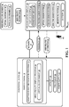
- FIG. 1 shows a schematic view of one aspect of an adaptive event recognition system 10.
- the adaptive event recognition system 10 includes an adaptive event recognition program 14 that may be stored in mass storage 18 of a computing device 22.
- the adaptive event recognition program 14 may be loaded into memory 26 and executed by a processor 30 of the computing device 22 to perform one or more of the methods and processes described in more detail below.
- the computing device 22 may further include a power supply 32, such as a battery, for supplying power to components of the computing device.
- the adaptive event recognition system 10 includes a mixed reality display program 34 that may generate a virtual environment 38 for display via a display device, such as the head-mounted display (HMD) device 42, to create a mixed reality environment 44.
- the mixed reality environment includes the virtual environment 38 displayed within a physical environment 48.
- user-related information 52 may be received from the physical environment 48 via the HMD device 42.
- the computing device 22 may take the form of a desktop computing device, a mobile computing device such as a smart phone, laptop, notebook or tablet computer, network computer, home entertainment computer, interactive television, gaming system, or other suitable type of computing device. Additional details regarding the components and computing aspects of the computing device 22 are described in more detail below with reference to FIG. 7 .
- the computing device 22 may be operatively connected with the HMD device 42 using a wired connection, or may employ a wireless connection via WiFi, Bluetooth, or any other suitable wireless communication protocol.
- the computing device 22 may be communicatively coupled to a network 16.
- the network 16 may take the form of a local area network (LAN), wide area network (WAN), wired network, wireless network, personal area network, or a combination thereof, and may include the Internet.
- the computing device 22 may also communicate with one or more other computing devices via network 16. Additionally, the example illustrated in FIG. 1 shows the computing device 22 as a separate component from the HMD device 42. It will be appreciated that in other examples the computing device 22 may be integrated into the HMD device 42.
- an HMD device 200 in the form of a pair of wearable glasses with a transparent display 54 is provided.
- the HMD device 200 may take other suitable forms in which a transparent, semi-transparent or non-transparent display is supported in front of a viewer's eye or eyes.
- the HMD device 42 shown in FIG. 1 may take the form of the HMD device 200, as described in more detail below, or any other suitable HMD device.
- display devices may include hand-held smart phones, tablet computers, and other suitable display devices.
- the HMD device 42 includes a display system 56 and transparent display 54 that enable images such as holographic objects to be delivered to the eyes of a user 46.
- the transparent display 54 may be configured to visually augment an appearance of a physical environment 48 to a user 46 viewing the physical environment through the transparent display.
- the appearance of the physical environment 48 may be augmented by graphical content (e.g., one or more pixels each having a respective color and brightness) that is presented via the transparent display 54 to create a mixed reality environment.
- the transparent display 54 may also be configured to enable a user to view a physical, real-world object in the physical environment 48 through one or more partially transparent pixels that are displaying a virtual object representation.
- the transparent display 54 may include image-producing elements located within lenses 204 (such as, for example, a see-through Organic Light-Emitting Diode (OLED) display).
- the transparent display 54 may include a light modulator on an edge of the lenses 204.
- the lenses 204 may serve as a light guide for delivering light from the light modulator to the eyes of a user. Such a light guide may enable a user to perceive a 3D holographic image located within the physical environment 48 that the user is viewing, while also allowing the user to view physical objects in the physical environment, thus creating a mixed reality environment 44.
- the HMD device 42 may also include various sensors and related systems.
- the HMD device 42 may include an eye-tracking system 60 that utilizes at least one inward facing sensor 208.
- the inward facing sensor 208 may be an image sensor that is configured to acquire image data in the form of eye-tracking data from a user's eyes.
- the eye-tracking system 60 may use this information to track a position and/or movement of the user's eyes.
- the eye-tracking system 60 includes a gaze detection subsystem configured to detect a direction of gaze of each eye of a user.
- the gaze detection subsystem may be configured to determine gaze directions of each of a user's eyes in any suitable manner.
- the gaze detection subsystem may comprise one or more light sources, such as infrared light sources, configured to cause a glint of light to reflect from the cornea of each eye of a user.
- One or more image sensors may then be configured to capture an image of the user's eyes.
- eye-tracking system 60 may also be employed as a user input device for providing user-related information 52, such that a user may interact with the HMD device 42 via movements of the user's eyes.
- the HMD device 42 may also include sensor systems that receive physical environment data, such as user-related information 52, from the physical environment 48.
- the HMD device 42 may include an optical sensor system 62 that utilizes at least one outward facing sensor 212, such as an optical sensor, to capture image data from the physical environment 48.
- Outward facing sensor 212 may detect movements within its field of view, such as gesture-based inputs or other movements performed by a user 46 or by a person or physical object within the field of view.
- Outward facing sensor 212 may also capture two-dimensional image information and depth information from physical environment 48 and physical objects within the environment.
- outward facing sensor 212 may include a depth camera, a visible light camera, an infrared light camera, and/or a position tracking camera.
- the HMD device 42 may include depth sensing via one or more depth cameras.
- each depth camera may include left and right cameras of a stereoscopic vision system. Time-resolved images from one or more of these depth cameras may be registered to each other and/or to images from another optical sensor such as a visible spectrum camera, and may be combined to yield depth-resolved video.
- a structured light depth camera may be configured to project a structured infrared illumination, and to image the illumination reflected from a scene onto which the illumination is projected.
- a depth map of the scene may be constructed based on spacings between adjacent features in the various regions of an imaged scene.
- a depth camera may take the form of a time-of-flight depth camera configured to project a pulsed infrared illumination onto a scene and detect the illumination reflected from the scene. It will be appreciated that any other suitable depth camera may be used.
- Outward facing sensor 212 may capture images of the physical environment 48 in which a user 46 is situated.
- the mixed reality display program 34 may include a 3D modeling system that uses such input to generate a virtual environment 38 that models the physical environment 48 surrounding the user 46.
- the HMD device 42 may also include a position sensor system 66 that utilizes one or more motion sensors 220 to capture position data, and thereby enable motion detection, position tracking and/or orientation sensing of the HMD device.
- the position sensor system 66 may be utilized to determine a direction, velocity and/or acceleration of a user's head.
- the position sensor system 66 may also be utilized to determine a head pose orientation of a user's head.
- position sensor system 66 may comprise an inertial measurement unit configured as a six-axis or six-degree of freedom position sensor system.
- This example position sensor system may, for example, include three accelerometers and three gyroscopes to indicate or measure a change in location of the HMD device 42 within three-dimensional space along three orthogonal axes (e.g., x, y, z), and a change in an orientation of the HMD device about the three orthogonal axes (e.g., roll, pitch, yaw).
- three accelerometers and three gyroscopes to indicate or measure a change in location of the HMD device 42 within three-dimensional space along three orthogonal axes (e.g., x, y, z), and a change in an orientation of the HMD device about the three orthogonal axes (e.g., roll, pitch, yaw).
- Position sensor system 66 may also support other suitable positioning techniques, such as GPS or other global navigation systems. Further, while specific examples of position sensor systems have been described, it will be appreciated that other suitable position sensor systems may be used. In some examples, motion sensors 220 may also be employed as user input devices for providing user-related information 52, such that a user may interact with the HMD device 42 via gestures of the neck and head, or even of the body.
- the HMD device 42 may also include a biometric sensor system 70 that utilizes one or more biometric sensors 232 to capture user biometric data.
- the biometric sensor system 70 may be utilized to measure or determine user biometric data including, for example, heart rate, pupillary response, hemoglobin saturation, skin conductivity, respiration, perspiration, and brainwave activity.
- the HMD device 42 may also include a microphone system 72 that includes one or more microphones 224 that capture audio data. In other examples, audio may be presented to the user via one or more speakers 228 on the HMD device 42.
- the first HMD device 42 may also include a battery 74 or other suitable portable power supply that provides power to the various components of the HMD device.
- the HMD device 42 may also include a processor 236 having a logic subsystem and a storage subsystem, as discussed in more detail below with respect to FIG. 7 , that are in communication with the various sensors and systems of the HMD device.
- the storage subsystem may include instructions that are executable by the logic subsystem to receive signal inputs from the sensors and forward such inputs to computing device 22 (in unprocessed or processed form), and to present images to a user via the transparent display 54.
- the HMD device 42 and related sensors and other components described above and illustrated in FIGS. 1 and 2 are provided by way of example. These examples are not intended to be limiting in any manner, as any other suitable sensors, components, and/or combination of sensors and components may be utilized. Therefore it is to be understood that the HMD device 42 may include additional and/or alternative sensors, cameras, microphones, input devices, output devices, etc. Further, the physical configuration of the HMD device 42 and its various sensors and subcomponents may take a variety of different forms.
- the various sensor systems and related components may be operated at various polling rates or frequencies to monitor for user-related information 52 provided by user 46.
- the polling rates of one or more sensors may be controlled in response to determining whether user-related information 52 matches a pre-event.
- user-related information 52 in the form of hand movements and corresponding gestures are received by the optical sensor system 62. It will be appreciated that in other examples many other forms of user-related information 52 may be received and utilized by the adaptive event recognition system 10 to control sensor operation as described in more detail below. Such other forms of user-related information 52 include, but are not limited to, other user movement data, eye-tracking data, position data, biometric data and audio data.
- FIG. 3 is a schematic illustration of pre-events in the form of hand movements leading to a selected target event comprising a target gesture.
- one or more optical sensors in the optical sensor system 62 of HMD device 42 may capture image data of a user's hand 304 executing a hand gesture.
- the index finger 308 and thumb 312 make a pinching gesture in which the user begins with the finger and thumb forming an open, generally U-shaped pose 316. From this pose 316 the user closes the gap between the index finger 308 and thumb 312 until the finger and thumb meet to make a pinching pose 330.
- the adaptive event recognition system 10 may provide feedback 78 to the user 46 via the HMD device 42.
- Feedback 78 may comprise, for example, the execution of a command with respect to a program running via the HMD device 42.
- the pinching gesture illustrated in FIG. 3 may be used by a photography application to capture a photo of the physical environment 48.
- the feedback 78 may also include an indication to the user that a photo has been captured, such as providing a shutter release sound, a flashing icon, etc., via the HMD device 42.
- feedback 78 may comprise any other command utilized in a user input context, such as selecting, copying or pasting an element displayed to the user via HMD device 42.
- the command may control an operational aspect of the HMD device 42 or other electronic device. It will be appreciated that the foregoing examples are merely illustrative, and that feedback 78 may comprise any command, action, notification, or other event that is associated with a selected target event, such as a target gesture, and is provided to a user.
- any latency between a user input such as a target gesture and the associated feedback is desirably minimized.
- minimizing latency may include continually operating sensors at a high polling rates that use more power, impose greater computational burdens and correspondingly reduce battery life.
- the adaptive event recognition system 10 may reduce latency while also minimizing power usage and computational burden, thereby enabling enhanced battery life.
- the adaptive event recognition program 14 may be configured to receive user-related information 52 comprising image data from the optical sensor system 62 showing the user's hand 304 in a variety of poses, including the poses shown in FIG. 3 .
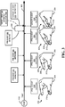
- the adaptive event recognition program 14 may be configured to operate a selected sensor from the optical sensor system 62 at a default polling rate that corresponds to a highest potential latency.
- the default polling rate may be, for example, 0.5 Hz., 1.0 Hz., 5.0 Hz., or any other suitable frequency. Such default polling rate may also correspond to a lowest power consumption state of the selected sensor.
- the selected sensor operating at the default polling rate may receive user-related information 52, such as image data of the user's hand 304, and provide such information to the adaptive event recognition program 14.
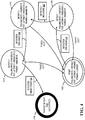
- the adaptive event recognition program 14 may then determine whether such information matches one of a plurality of pre-events (PE).
- PE pre-events
- the adaptive event recognition program 14 may determine whether user-related information 52 matches PE 506, PE 510, PE 514 or PE 518.
- each of the pre-events PE 506, PE 510, PE 514 and PE 518 corresponds to one or more different patterns of pre-events, and each of the patterns leads to a different possible target event (TE).
- PE 510 corresponds to 3 different patterns, indicated at 522, 526 and 530, that lead to 3 different target events TE 534, TE 538 and TE 542, respectively.
- a polling rate of a selected sensor may be increased to reduce latency. Further, until a subsequent pre-event is detected, the polling rate of a selected sensor may remain at a relatively lower rate to thereby conserve power and enhance battery life.
- the adaptive event recognition program 14 may receive image data of the user's hand 304 making the generally U-shaped pose 316.
- the adaptive event recognition program 14 may determine that the generally U-shaped pose 316 matches PE 510 in FIG. 5 .
- PE 510 is a member of patterns 522, 526 and 530.
- the adaptive event recognition program 14 may advance to a Detect1 state 406 in which the polling rate of the selected sensor is increased to operate at a Faster F1 polling rate that is faster than the default polling rate of the Start state 402.
- the default polling rate is 1.0 Hz.
- the Faster F1 polling rate may be 10 Hz.
- the increased Faster F1 polling rate of the Detect1 state 406 also corresponds to increased power usage by the selected sensor, indicated as Higher P1, as compared to power usage of the Start state 402.
- the Faster F1 polling rate of the Detect1 state 406 also corresponds to a reduced potential latency, indicated as Reduced L1, that is less than the highest potential latency of the Start state 402.
- a potential latency of a sensor operating at a given polling rate is defined as a maximum potential time period between the occurrence of an event, such as a pre-event or a target event, and the detection of the event occurrence by the sensor.
- a potential latency associated with this polling rate may be approximately 0.99 secs. In other words, approximately 0.99 secs would be the maximum potential elapsed time between the occurrence of an event, such as a pre-event or a target event, and the detection of the event occurrence by the sensor. Accordingly, increasing a sensor's polling rate correspondingly decreases the potential latency of that sensor. It will also be appreciated that in some examples, the actual latency between the occurrence of an event and the detection of the event occurrence by the sensor will be less than the potential latency of that sensor operating.
- the adaptive event recognition program 14 may receive image data of the user's hand 304 making a modified U-shaped pose 320 in which the index finger 308 and thumb 312 are closer together than in previous pose 316.
- the adaptive event recognition program 14 may determine that the modified U-shaped pose 320 matches PE 550 in FIG. 5 .
- PE 550 is a member of patterns 522 and 526. Thus, the possible target events have been reduced to TE 534 and TE 538.
- the adaptive event recognition program 14 may advance to a Detect2 state 410 in which the polling rate of the selected sensor is increased to operate at a Faster F2 polling rate that is faster than the Faster F1 polling rate of the Detect1 state 406.
- a Faster F2 polling rate that is faster than the Faster F1 polling rate of the Detect1 state 406.
- the increased Faster F2 polling rate of the Detect2 state 410 also corresponds to increased power usage by the selected sensor, indicated as Higher P2, as compared to the Higher P1 power usage of the Detect1 state 406.
- the Faster F2 polling rate of the Detect2 state 410 also corresponds to a further reduced potential latency, indicated as Reduced L2, that is less than the Reduced L1 potential latency of the Detect1 state 406.
- the adaptive event recognition program 14 may receive image data of the user's hand 304 making a near-pinching pose 324 in which the index finger 308 and thumb 312 are separated by a smaller distance, such as approximately 2 mm., as compared to the modified U-shaped pose 320.
- the adaptive event recognition program 14 may determine that the near-pinching pose 324 matches PE 554 in FIG. 5 .
- PE 554 is a member of pattern 522.
- the adaptive event recognition program 14 may advance to a Detect3 state 414 in which the polling rate of the selected sensor is increased to operate at a Faster F3 polling rate that is faster than the Faster F2 polling rate of the Detect2 state 410.
- the Faster F3 polling rate may be 120 Hz.
- the increased Faster F3 polling rate of the Detect3 state 414 also corresponds to increased power usage by the selected sensor, indicated as Higher P3, as compared to the Higher P2 power usage of the Detect2 state 410.
- the Faster F3 polling rate of the Detect3 state 414 also corresponds to a further reduced potential latency, indicated as Reduced L3, that is less than the Reduced L2 potential latency of the Detect2 state 410.
- the adaptive event recognition program 14 may receive image data of the user's hand 304 making the pinching pose 330 in which the index finger 308 and thumb 312 are touching, as indicated by the Target Event 534 Occurred state 418.
- the adaptive event recognition program 14 may determine that the pinching pose 330 matches selected target event TE 534 in FIG. 5 .
- the adaptive event recognition program 14 may then provide feedback associated with the selected target event TE 534 to the user via the HMD device 42.
- the adaptive event recognition program 14 may be configured to reduce the polling rate of the selected sensor where user-related information 52 corresponding to a pre-event is not received within a predetermined timeframe. For example, when the Detect1 state is initiated the adaptive event recognition program 14 may start a timer. If user-related information 52 corresponding to one of the next possible pre-events PE 550 and PE 552 is not received within a predetermined timeframe, then the adaptive event recognition program 14 may effect a timed out condition and revert to the Start state 402 corresponding to the slower, Default polling rate and lowest power usage.
- Similar time out conditions may be utilized for the Detect2 and/or Detect3 states.
- power consumption may be reduced when a probability of receiving a next possible pre-event falls below a predetermined threshold that corresponds to the predetermined timeframe.
- the predetermined timeframes for a time out condition may be 3 secs. for the Detect1 state, 2 secs for the Detect2 state, and 1.0 sec for the Detect3 state. It will be appreciated that any suitable predetermined timeframes and predetermined probability thresholds may be utilized.
- the adaptive event recognition system 10 minimizes power usage by the sensor as well as bandwidth consumption of sensor signals. For example, by waiting to operate the sensor at the highest Faster F3 polling until PE 554 is detected, the highest Higher P3 power usage state may be avoided until a probability of the selected target event occurring exceeds a predetermined threshold.
- the adaptive event recognition system 10 sequentially increases the polling rate of the selected sensor as additional pre-events are detected. In this manner and as illustrated in FIG. 3 , the corresponding potential latencies between the occurrence and detection of a pre-event are sequentially reduced. Furthermore, by operating the sensor at the highest Faster F3 polling rate upon detecting PE 554, the adaptive event recognition system 10 also minimizes potential latency between the occurrence of the selected target event TE 534 and detecting the event.
- the adaptive event recognition program 14 may pre-fetch at least a portion of the feedback 78 associated with one or more target events. For example, at the Detect2 state 410, which corresponds to PE 550 in FIG. 5 , there are two possible patterns 522 and 526 and two possible target events TE 534 and TE 538, respectively, remaining. In this example, at the Detect2 state 410 the adaptive event recognition program 14 may pre-fetch a portion of the feedback 78 associated with both TE 534 and TE 538. In one example, 50% of the feedback 78 associated with both TE 534 and TE 538 may be pre-fetched. It will be appreciated that any suitable portion of feedback may be pre-fetched. In some examples, 100% of the feedback may be pre-fetched.
- the adaptive event recognition program 14 may pre-fetch 50% of the data associated with the command and 50% of the image data that will be provided to the user via the HMD device 42 to indicate that an image has been captured.
- the adaptive event recognition program 14 may pre-fetch 50% of the data associated with the zoom command and 50% of the image data that will be provided to the user via the HMD device 42 to indicate that the camera is zooming.
- the adaptive event recognition program 14 may pre-fetch at least a portion of the feedback 78 associated with one or more target events at other points in time that temporally precede the one or more target events along timeline 302.
- the adaptive event recognition program 14 may pre-fetch at least a portion of feedback at the Detect3 state 414, which corresponds to PE 554 in FIG. 5 , or at the Detect1 state 406, which corresponds to PE 510 in FIG. 5 .
- the adaptive event recognition program 14 may be configured to determine an estimated execution time at which the selected target event will occur. For example, from the Detect2 state 410 the adaptive event recognition program 14 may receive user-related information 52 that matches PE 554. PE 554 may be a predictive pre-event that corresponds to a predetermined likelihood that target event TE 534 will subsequently occur.
- the adaptive event recognition program 14 may determine a Target Event 534 Estimated Execution Time at which the target event 534 will occur.
- the Target Event 534 Estimated Execution Time may be determined by accessing a predetermined estimated time gap, illustrated at 340 in FIG. 3 , between the detection of PE 554 and the occurrence of the target event 534. As shown in FIG. 3 , by adding the estimated time gap 340 to the actual time at which the pre-event 554 was detected, the Target Event 534 Estimated Execution Time may be determined.
- the adaptive event recognition program 14 may provide feedback 78 associated with the selected target event to the user either at the Target Event 534 Estimated Execution Time or prior to the Target Event 534 Estimated Execution Time.
- the feedback 78 may be provided at the Target Event 534 Estimated Execution Time which may closely correspond to the actual time that the target event TE 534 occurs.
- the user may experience a perceived latency that is effectively zero or perhaps negligible.
- the feedback 78 may be provided prior to the Target Event 534 Estimated Execution Time by a predetermined time period.
- the user may experience a negative perceived latency in which the feedback 78 is perceived by the user before the target event TE 534 is completed. In some examples, this may provide the user with a heightened experience of real-time interaction with the HMD device 42 and adaptive event recognition system 10.
- providing the feedback 78 prior to the Target Event 534 Estimated Execution Time may also be utilized to offset processing and/or other system delays and latencies that may be associated with providing the feedback to the user via the HMD device 42. In this manner, the latency associated with the feedback 78 that is perceived by the user may be minimized.
- any suitable sensor polling rates and temporal progression of increased polling rates may be utilized.
- any suitable poses, gestures, or other hand movements may be designated as pre-events and target events.
- HMD device 42 may provide such information to the adaptive event recognition program 14. Such information may be correlated with other pre-events, patterns, and associated target events that relate to the information.
- pre-events and patterns of FIG. 5 may be determined empirically through laboratory studies, user studies or any other suitable methods. Estimated time gaps between the occurrence of pre-events and the execution of target events may be similarly determined through laboratory studies, user studies or any other suitable methods. Where a selected target event is predicted, a threshold probability of the selected target event occurring following a penultimate pre-event may be utilized to decrease the occurrence of prediction errors. In some examples, pre-events, target events, patterns, and estimated time gaps may be stored in mass storage 18 of computing device 22 or at a remote source that is accessed via network 16.
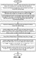
- FIGS. 6A and 6B illustrate a flow chart of a method 600 for recognizing a selected target event according to an aspect of the present disclosure.
- the following description of method 600 is provided with reference to the software and hardware components of the adaptive event recognition system 10 described above and shown in FIGS. 1 and 2 . It will be appreciated that method 600 may also be performed in other contexts using other suitable hardware and software components.
- the method 600 includes, in a display device comprising a plurality of sensors, operating a selected sensor of the plurality of sensors at a first polling rate corresponding to a higher potential latency.
- the plurality of input sensors may be selected from image sensors, position sensors, microphones, eye-tracking sensors, and biometric sensors.
- the display device is a head-mounted display device.
- the method 600 may include receiving initial user-related information from the selected sensor.
- the method 600 may include controlling the selected sensor to operate at a timed out polling rate that is slower than the first polling rate.
- the method 600 may include determining whether the initial user-related information matches one of a plurality of pre-events, wherein each of the pre-events corresponds to one or more different patterns of pre-events, and each of the patterns leads to a different possible target event.
- each of the patterns may comprise a different sequence of the pre-events.
- the method 600 may include operating the selected sensor at a second polling rate that is faster than the first polling rate and that corresponds to a lower potential latency that is less than the higher potential latency.
- the method 600 may include pre-fetching at least a portion of the feedback associated with the selected target event.
- the method 600 may include receiving intermediate user-related information from the selected sensor.
- the method 600 may include determining whether the intermediate user-related information matches a pre-event from a subset of the plurality of pre-events.
- the method 600 may include operating the selected sensor at a third polling rate that is faster than the first polling rate and is slower than the second polling rate.
- the method 600 may include receiving subsequent user-related information from the selected sensor.
- the method 600 may include providing feedback associated with the selected target event to the user via the display device.
- the selected target event may comprise a hand gesture.
- the method 600 may include determining an estimated execution time at which the selected target event will occur.
- the method may include providing the feedback associated with the selected target event to the user either at the estimated execution time or prior to the estimated execution time.
- method 600 is provided by way of example and is not meant to be limiting. Therefore, it is to be understood that method 600 may include additional and/or alternative steps than those illustrated in FIGS. 6A and 6B . Further, it is to be understood that method 600 may be performed in any suitable order. Further still, it is to be understood that one or more steps may be omitted from method 600.
- FIG. 7 schematically shows a nonlimiting aspect of a computing system 700 that may perform one or more of the above described methods and processes.
- Computing device 22 may take the form of computing system 700.
- Computing system 700 is shown in simplified form. It is to be understood that virtually any computer architecture may be used.
- computing system 700 may take the form of a mainframe computer, server computer, desktop computer, laptop computer, tablet computer, home entertainment computer, network computing device, mobile computing device, mobile communication device, gaming device, etc.
- the computing system 700 may be integrated into an HMD device.
- computing system 700 includes a logic subsystem 704 and a storage subsystem 708.
- Computing system 700 may optionally include a display subsystem 712, a communication subsystem 716, a sensor subsystem 720, an input subsystem 722 and/or other subsystems and components not shown in FIG. 7 .
- Computing system 700 may also include computer readable media, with the computer readable media including computer readable storage media and computer readable communication media.
- Computing system 700 may also optionally include other user input devices such as keyboards, mice, game controllers, and/or touch screens, for example.
- the methods and processes described herein may be implemented as a computer application, computer service, computer API, computer library, and/or other computer program product in a computing system that includes one or more computers.
- Logic subsystem 704 may include one or more physical devices configured to execute one or more instructions.
- the logic subsystem 704 may be configured to execute one or more instructions that are part of one or more applications, services, programs, routines, libraries, objects, components, data structures, or other logical constructs. Such instructions may be implemented to perform a task, implement a data type, transform the state of one or more devices, or otherwise arrive at a desired result.
- the logic subsystem 704 may include one or more processors that are configured to execute software instructions. Additionally or alternatively, the logic subsystem may include one or more hardware or firmware logic machines configured to execute hardware or firmware instructions. Processors of the logic subsystem may be single core or multicore, and the programs executed thereon may be configured for parallel or distributed processing. The logic subsystem may optionally include individual components that are distributed throughout two or more devices, which may be remotely located and/or configured for coordinated processing. One or more aspects of the logic subsystem may be virtualized and executed by remotely accessible networked computing devices configured in a cloud computing configuration.
- Storage subsystem 708 may include one or more physical, persistent devices configured to hold data and/or instructions executable by the logic subsystem 704 to implement the herein described methods and processes. When such methods and processes are implemented, the state of storage subsystem 708 may be transformed (e.g., to hold different data).
- Storage subsystem 708 may include removable media and/or built-in devices.
- Storage subsystem 708 may include optical memory devices (e.g., CD, DVD, HD-DVD, Blu-Ray Disc, etc.), semiconductor memory devices (e.g., RAM, EPROM, EEPROM, etc.) and/or magnetic memory devices (e.g., hard disk drive, floppy disk drive, tape drive, MRAM, etc.), among others.
- Storage subsystem 708 may include devices with one or more of the following characteristics: volatile, nonvolatile, dynamic, static, read/write, read-only, random access, sequential access, location addressable, file addressable, and content addressable.
- aspects of logic subsystem 704 and storage subsystem 708 may be integrated into one or more common devices through which the functionally described herein may be enacted, at least in part.
- Such hardware-logic components may include field-programmable gate arrays (FPGAs), program- and application-specific integrated circuits (PASIC / ASICs), program- and application-specific standard products (PSSP / ASSPs), system-on-a-chip (SOC) systems, and complex programmable logic devices (CPLDs), for example.
- FIG. 7 also shows an aspect of the storage subsystem 708 in the form of removable computer readable storage media 724, which may be used to store data and/or instructions executable to implement the methods and processes described herein.
- Removable computer-readable storage media 724 may take the form of CDs, DVDs, HD-DVDs, Blu-Ray Discs, EEPROMs, and/or floppy disks, among others.
- storage subsystem 708 includes one or more physical, persistent devices.
- aspects of the instructions described herein may be propagated in a transitory fashion by a pure signal (e.g., an electromagnetic signal, an optical signal, etc.) that is not held by a physical device for at least a finite duration.
- a pure signal e.g., an electromagnetic signal, an optical signal, etc.
- data and/or other forms of information pertaining to the present disclosure may be propagated by a pure signal via computer-readable communication media.
- display subsystem 712 may be used to present a visual representation of data held by storage subsystem 708. As the above described methods and processes change the data held by the storage subsystem 708, and thus transform the state of the storage subsystem, the state of the display subsystem 712 may likewise be transformed to visually represent changes in the underlying data.
- the display subsystem 712 may include one or more display devices utilizing virtually any type of technology. Such display devices may be combined with logic subsystem 704 and/or storage subsystem 708 in a shared enclosure, or such display devices may be peripheral display devices.
- the display subsystem 712 may include, for example, the display system 56 and transparent display 54 of the HMD device 42.
- communication subsystem 716 may be configured to communicatively couple computing system 700 with one or more networks and/or one or more other computing devices.
- Communication subsystem 716 may include wired and/or wireless communication devices compatible with one or more different communication protocols.
- the communication subsystem 716 may be configured for communication via a wireless telephone network, a wireless local area network, a wired local area network, a wireless wide area network, a wired wide area network, etc.
- the communication subsystem may allow computing system 700 to send and/or receive messages to and/or from other devices via a network such as the Internet.
- Sensor subsystem 720 may include one or more sensors configured to sense different physical phenomenon (e.g., visible light, infrared light, sound, acceleration, orientation, position, etc.) and/or physiological processes, functions, measurements, and/or states as described above.
- the sensor subsystem 720 may comprise one or more eye-tracking sensors, image sensors, microphones, motion sensors such as accelerometers, compasses, touch pads, touch screens, heart rate monitors, pulse oximeters, electrodermal response sensors, electroencephalographic (EEG) monitors, and/or any other suitable sensors.
- EEG electroencephalographic
- sensor subsystem 720 may include a depth camera.
- the depth camera may include left and right cameras of a stereoscopic vision system, for example. Time-resolved images from both cameras may be registered to each other and combined to yield depth-resolved video.
- the depth camera may be a structured light depth camera or a time-of-flight camera, as described above.
- sensor subsystem 720 may include a visible light camera, such as a digital camera. Virtually any type of digital camera technology may be used.
- the visible light camera may include a charge coupled device image sensor.
- Sensor subsystem 720 may be configured to provide sensor data to logic subsystem 704, for example.
- data may include eye-tracking information, image information, audio information, ambient lighting information, depth information, position information, motion information, user location information, biometric parameter information, and/or any other suitable sensor data that may be used to perform the methods and processes described above.
- input subsystem 722 may comprise or interface with one or more sensors or user-input devices such as a game controller, gesture input detection device, voice recognizer, inertial measurement unit, keyboard, mouse, or touch screen.
- the input subsystem 722 may comprise or interface with selected natural user input (NUI) componentry.
- NUI natural user input
- Such componentry may be integrated or peripheral, and the transduction and/or processing of input actions may be handled on- or off-board.
- Example NUI componentry may include a microphone for speech and/or voice recognition; an infrared, color, stereoscopic, and/or depth camera for machine vision and/or gesture recognition; a head tracker, eye tracker, accelerometer, and/or gyroscope for motion detection and/or intent recognition; as well as electric-field sensing componentry for assessing brain activity.
- program may be used to describe an aspect of the adaptive event recognition system 10 that is implemented to perform one or more particular functions. In some cases, such a program may be instantiated via logic subsystem 704 executing instructions held by storage subsystem 708. It is to be understood that different programs may be instantiated from the same application, service, code block, object, library, routine, API, function, etc. Likewise, the same program may be instantiated by different applications, services, code blocks, objects, routines, APIs, functions, etc.
- program is meant to encompass individual or groups of executable files, data files, libraries, drivers, scripts, database records, etc.
Landscapes
- Engineering & Computer Science (AREA)
- Theoretical Computer Science (AREA)
- Physics & Mathematics (AREA)
- General Physics & Mathematics (AREA)
- General Engineering & Computer Science (AREA)
- Human Computer Interaction (AREA)
- Multimedia (AREA)
- Computer Hardware Design (AREA)
- Computer Vision & Pattern Recognition (AREA)
- Artificial Intelligence (AREA)
- Health & Medical Sciences (AREA)
- General Health & Medical Sciences (AREA)
- Ophthalmology & Optometry (AREA)
- User Interface Of Digital Computer (AREA)
- Digital Computer Display Output (AREA)
- Optics & Photonics (AREA)
- Measuring Pulse, Heart Rate, Blood Pressure Or Blood Flow (AREA)
- Control Of Indicators Other Than Cathode Ray Tubes (AREA)
Applications Claiming Priority (2)
| Application Number | Priority Date | Filing Date | Title |
|---|---|---|---|
| US13/927,051 US8988345B2 (en) | 2013-06-25 | 2013-06-25 | Adaptive event recognition |
| PCT/US2014/043307 WO2014209773A1 (en) | 2013-06-25 | 2014-06-20 | Adaptive event recognition |
Publications (2)
| Publication Number | Publication Date |
|---|---|
| EP3014391A1 EP3014391A1 (en) | 2016-05-04 |
| EP3014391B1 true EP3014391B1 (en) | 2019-06-05 |
Family
ID=51210776
Family Applications (1)
| Application Number | Title | Priority Date | Filing Date |
|---|---|---|---|
| EP14740039.4A Active EP3014391B1 (en) | 2013-06-25 | 2014-06-20 | Adaptive event recognition |
Country Status (11)
| Country | Link |
|---|---|
| US (1) | US8988345B2 (pt) |
| EP (1) | EP3014391B1 (pt) |
| JP (1) | JP6348176B2 (pt) |
| KR (1) | KR102272968B1 (pt) |
| CN (1) | CN105393191B (pt) |
| AU (1) | AU2014302875B2 (pt) |
| BR (1) | BR112015032026B1 (pt) |
| CA (1) | CA2914061C (pt) |
| MX (1) | MX352773B (pt) |
| RU (1) | RU2684189C2 (pt) |
| WO (1) | WO2014209773A1 (pt) |
Families Citing this family (83)
| Publication number | Priority date | Publication date | Assignee | Title |
|---|---|---|---|---|
| US9158116B1 (en) | 2014-04-25 | 2015-10-13 | Osterhout Group, Inc. | Temple and ear horn assembly for headworn computer |
| US9400390B2 (en) | 2014-01-24 | 2016-07-26 | Osterhout Group, Inc. | Peripheral lighting for head worn computing |
| US9952664B2 (en) | 2014-01-21 | 2018-04-24 | Osterhout Group, Inc. | Eye imaging in head worn computing |
| US9715112B2 (en) | 2014-01-21 | 2017-07-25 | Osterhout Group, Inc. | Suppression of stray light in head worn computing |
| US9298007B2 (en) | 2014-01-21 | 2016-03-29 | Osterhout Group, Inc. | Eye imaging in head worn computing |
| US9229233B2 (en) | 2014-02-11 | 2016-01-05 | Osterhout Group, Inc. | Micro Doppler presentations in head worn computing |
| US9965681B2 (en) | 2008-12-16 | 2018-05-08 | Osterhout Group, Inc. | Eye imaging in head worn computing |
| US9814426B2 (en) | 2012-06-14 | 2017-11-14 | Medibotics Llc | Mobile wearable electromagnetic brain activity monitor |
| US10234942B2 (en) | 2014-01-28 | 2019-03-19 | Medibotics Llc | Wearable and mobile brain computer interface (BCI) device and method |
| US9968297B2 (en) | 2012-06-14 | 2018-05-15 | Medibotics Llc | EEG glasses (electroencephalographic eyewear) |
| US11662819B2 (en) | 2015-05-12 | 2023-05-30 | Medibotics | Method for interpreting a word, phrase, and/or command from electromagnetic brain activity |
| US11172859B2 (en) | 2014-01-28 | 2021-11-16 | Medibotics | Wearable brain activity device with auditory interface |
| US10130277B2 (en) | 2014-01-28 | 2018-11-20 | Medibotics Llc | Willpower glasses (TM)—a wearable food consumption monitor |
| US9428072B2 (en) * | 2014-01-09 | 2016-08-30 | Ford Global Technologies, Llc | Method and system for extending battery life |
| US10254856B2 (en) | 2014-01-17 | 2019-04-09 | Osterhout Group, Inc. | External user interface for head worn computing |
| US9841599B2 (en) | 2014-06-05 | 2017-12-12 | Osterhout Group, Inc. | Optical configurations for head-worn see-through displays |
| US20160019715A1 (en) | 2014-07-15 | 2016-01-21 | Osterhout Group, Inc. | Content presentation in head worn computing |
| US10684687B2 (en) | 2014-12-03 | 2020-06-16 | Mentor Acquisition One, Llc | See-through computer display systems |
| US9810906B2 (en) | 2014-06-17 | 2017-11-07 | Osterhout Group, Inc. | External user interface for head worn computing |
| US9529195B2 (en) | 2014-01-21 | 2016-12-27 | Osterhout Group, Inc. | See-through computer display systems |
| US9575321B2 (en) | 2014-06-09 | 2017-02-21 | Osterhout Group, Inc. | Content presentation in head worn computing |
| US11227294B2 (en) | 2014-04-03 | 2022-01-18 | Mentor Acquisition One, Llc | Sight information collection in head worn computing |
| US10191279B2 (en) | 2014-03-17 | 2019-01-29 | Osterhout Group, Inc. | Eye imaging in head worn computing |
| US9594246B2 (en) | 2014-01-21 | 2017-03-14 | Osterhout Group, Inc. | See-through computer display systems |
| US9939934B2 (en) | 2014-01-17 | 2018-04-10 | Osterhout Group, Inc. | External user interface for head worn computing |
| US9299194B2 (en) | 2014-02-14 | 2016-03-29 | Osterhout Group, Inc. | Secure sharing in head worn computing |
| US11103122B2 (en) | 2014-07-15 | 2021-08-31 | Mentor Acquisition One, Llc | Content presentation in head worn computing |
| US9671613B2 (en) | 2014-09-26 | 2017-06-06 | Osterhout Group, Inc. | See-through computer display systems |
| US10649220B2 (en) | 2014-06-09 | 2020-05-12 | Mentor Acquisition One, Llc | Content presentation in head worn computing |
| US9829707B2 (en) | 2014-08-12 | 2017-11-28 | Osterhout Group, Inc. | Measuring content brightness in head worn computing |
| US9746686B2 (en) | 2014-05-19 | 2017-08-29 | Osterhout Group, Inc. | Content position calibration in head worn computing |
| US9753288B2 (en) | 2014-01-21 | 2017-09-05 | Osterhout Group, Inc. | See-through computer display systems |
| US9523856B2 (en) | 2014-01-21 | 2016-12-20 | Osterhout Group, Inc. | See-through computer display systems |
| US9836122B2 (en) | 2014-01-21 | 2017-12-05 | Osterhout Group, Inc. | Eye glint imaging in see-through computer display systems |
| US11892644B2 (en) | 2014-01-21 | 2024-02-06 | Mentor Acquisition One, Llc | See-through computer display systems |
| US9532714B2 (en) | 2014-01-21 | 2017-01-03 | Osterhout Group, Inc. | Eye imaging in head worn computing |
| US9766463B2 (en) | 2014-01-21 | 2017-09-19 | Osterhout Group, Inc. | See-through computer display systems |
| US9651784B2 (en) | 2014-01-21 | 2017-05-16 | Osterhout Group, Inc. | See-through computer display systems |
| US11669163B2 (en) | 2014-01-21 | 2023-06-06 | Mentor Acquisition One, Llc | Eye glint imaging in see-through computer display systems |
| US9494800B2 (en) | 2014-01-21 | 2016-11-15 | Osterhout Group, Inc. | See-through computer display systems |
| US11737666B2 (en) | 2014-01-21 | 2023-08-29 | Mentor Acquisition One, Llc | Eye imaging in head worn computing |
| US20150205135A1 (en) | 2014-01-21 | 2015-07-23 | Osterhout Group, Inc. | See-through computer display systems |
| US11487110B2 (en) | 2014-01-21 | 2022-11-01 | Mentor Acquisition One, Llc | Eye imaging in head worn computing |
| US9811159B2 (en) | 2014-01-21 | 2017-11-07 | Osterhout Group, Inc. | Eye imaging in head worn computing |
| US9846308B2 (en) | 2014-01-24 | 2017-12-19 | Osterhout Group, Inc. | Haptic systems for head-worn computers |
| US20150241964A1 (en) | 2014-02-11 | 2015-08-27 | Osterhout Group, Inc. | Eye imaging in head worn computing |
| US9401540B2 (en) | 2014-02-11 | 2016-07-26 | Osterhout Group, Inc. | Spatial location presentation in head worn computing |
| US20160187651A1 (en) | 2014-03-28 | 2016-06-30 | Osterhout Group, Inc. | Safety for a vehicle operator with an hmd |
| US9423842B2 (en) | 2014-09-18 | 2016-08-23 | Osterhout Group, Inc. | Thermal management for head-worn computer |
| US9672210B2 (en) | 2014-04-25 | 2017-06-06 | Osterhout Group, Inc. | Language translation with head-worn computing |
| US20150309534A1 (en) | 2014-04-25 | 2015-10-29 | Osterhout Group, Inc. | Ear horn assembly for headworn computer |
| US9651787B2 (en) | 2014-04-25 | 2017-05-16 | Osterhout Group, Inc. | Speaker assembly for headworn computer |
| US10853589B2 (en) | 2014-04-25 | 2020-12-01 | Mentor Acquisition One, Llc | Language translation with head-worn computing |
| US10663740B2 (en) | 2014-06-09 | 2020-05-26 | Mentor Acquisition One, Llc | Content presentation in head worn computing |
| KR20160014418A (ko) * | 2014-07-29 | 2016-02-11 | 삼성전자주식회사 | 유저 인터페이스 장치 및 유저 인터페이스 방법 |
| US20160131904A1 (en) * | 2014-11-07 | 2016-05-12 | Osterhout Group, Inc. | Power management for head worn computing |
| US9684172B2 (en) | 2014-12-03 | 2017-06-20 | Osterhout Group, Inc. | Head worn computer display systems |
| US10317672B2 (en) * | 2014-12-11 | 2019-06-11 | AdHawk Microsystems | Eye-tracking system and method therefor |
| US10213105B2 (en) | 2014-12-11 | 2019-02-26 | AdHawk Microsystems | Eye-tracking system and method therefor |
| USD751552S1 (en) | 2014-12-31 | 2016-03-15 | Osterhout Group, Inc. | Computer glasses |
| USD753114S1 (en) | 2015-01-05 | 2016-04-05 | Osterhout Group, Inc. | Air mouse |
| US11119565B2 (en) | 2015-01-19 | 2021-09-14 | Samsung Electronics Company, Ltd. | Optical detection and analysis of bone |
| US20160239985A1 (en) | 2015-02-17 | 2016-08-18 | Osterhout Group, Inc. | See-through computer display systems |
| WO2017090298A1 (ja) * | 2015-11-26 | 2017-06-01 | 株式会社コロプラ | 仮想空間内オブジェクトへの動作指示方法、及びプログラム |
| US9880441B1 (en) | 2016-09-08 | 2018-01-30 | Osterhout Group, Inc. | Electrochromic systems for head-worn computer systems |
| US10824253B2 (en) | 2016-05-09 | 2020-11-03 | Mentor Acquisition One, Llc | User interface systems for head-worn computers |
| US10466491B2 (en) | 2016-06-01 | 2019-11-05 | Mentor Acquisition One, Llc | Modular systems for head-worn computers |
| US10684478B2 (en) | 2016-05-09 | 2020-06-16 | Mentor Acquisition One, Llc | User interface systems for head-worn computers |
| US10289196B2 (en) * | 2016-07-01 | 2019-05-14 | North Inc. | Techniques for ocular control |
| CN106027802B (zh) * | 2016-07-06 | 2020-01-03 | 捷开通讯(深圳)有限公司 | 移动终端及其参数设置方法 |
| US10690936B2 (en) | 2016-08-29 | 2020-06-23 | Mentor Acquisition One, Llc | Adjustable nose bridge assembly for headworn computer |
| USD840395S1 (en) | 2016-10-17 | 2019-02-12 | Osterhout Group, Inc. | Head-worn computer |
| WO2018106220A1 (en) * | 2016-12-06 | 2018-06-14 | Vuelosophy Inc. | Systems and methods for tracking motion and gesture of heads and eyes |
| USD864959S1 (en) | 2017-01-04 | 2019-10-29 | Mentor Acquisition One, Llc | Computer glasses |
| WO2018137767A1 (en) * | 2017-01-26 | 2018-08-02 | Telefonaktiebolaget Lm Ericsson (Publ) | Detection systems and methods |
| US20180235540A1 (en) | 2017-02-21 | 2018-08-23 | Bose Corporation | Collecting biologically-relevant information using an earpiece |
| US10213157B2 (en) * | 2017-06-09 | 2019-02-26 | Bose Corporation | Active unipolar dry electrode open ear wireless headset and brain computer interface |
| US10228899B2 (en) * | 2017-06-21 | 2019-03-12 | Motorola Mobility Llc | Monitoring environmental noise and data packets to display a transcription of call audio |
| US10921883B2 (en) * | 2019-01-17 | 2021-02-16 | International Business Machines Corporation | Eye tracking for management of mobile device |
| US11595462B2 (en) | 2019-09-09 | 2023-02-28 | Motorola Mobility Llc | In-call feedback to far end device of near end device constraints |
| US11425317B2 (en) * | 2020-01-22 | 2022-08-23 | Sling Media Pvt. Ltd. | Method and apparatus for interactive replacement of character faces in a video device |
| WO2022055475A1 (en) * | 2020-09-08 | 2022-03-17 | Hewlett-Packard Development Company, L.P. | Determinations of characteristics from biometric signals |
| WO2024059680A1 (en) * | 2022-09-15 | 2024-03-21 | Google Llc | Wearable device don/doff determination |
Family Cites Families (15)
| Publication number | Priority date | Publication date | Assignee | Title |
|---|---|---|---|---|
| US6359601B1 (en) * | 1993-09-14 | 2002-03-19 | Francis J. Maguire, Jr. | Method and apparatus for eye tracking |
| JPH0981323A (ja) | 1995-09-18 | 1997-03-28 | Toshiba Corp | A/d変換処理装置及びデータ処理装置 |
| US6127900A (en) * | 1998-09-30 | 2000-10-03 | Conexant Systems, Inc. | Dual frequency synthesis system |
| RU2370817C2 (ru) * | 2004-07-29 | 2009-10-20 | Самсунг Электроникс Ко., Лтд. | Система и способ отслеживания объекта |
| US7849041B2 (en) | 2006-09-18 | 2010-12-07 | Microsoft Corporation | Intent prediction and response employing sensing, networking, and communication among distributed devices |
| US7971156B2 (en) | 2007-01-12 | 2011-06-28 | International Business Machines Corporation | Controlling resource access based on user gesturing in a 3D captured image stream of the user |
| JP2008269174A (ja) * | 2007-04-18 | 2008-11-06 | Fujifilm Corp | 制御装置、方法およびプログラム |
| US8874129B2 (en) * | 2010-06-10 | 2014-10-28 | Qualcomm Incorporated | Pre-fetching information based on gesture and/or location |
| JP5601045B2 (ja) | 2010-06-24 | 2014-10-08 | ソニー株式会社 | ジェスチャ認識装置、ジェスチャ認識方法およびプログラム |
| US9122307B2 (en) * | 2010-09-20 | 2015-09-01 | Kopin Corporation | Advanced remote control of host application using motion and voice commands |
| US9619035B2 (en) | 2011-03-04 | 2017-04-11 | Microsoft Technology Licensing, Llc | Gesture detection and recognition |
| CN107643828B (zh) | 2011-08-11 | 2021-05-25 | 视力移动技术有限公司 | 车辆、控制车辆的方法 |
| US20130077820A1 (en) | 2011-09-26 | 2013-03-28 | Microsoft Corporation | Machine learning gesture detection |
| US9575544B2 (en) | 2011-11-07 | 2017-02-21 | Qualcomm Incorporated | Ultrasound based mobile receivers in idle mode |
| JP2013115649A (ja) * | 2011-11-29 | 2013-06-10 | Toshiba Corp | 制御装置、電力量制御方法 |
-
2013
- 2013-06-25 US US13/927,051 patent/US8988345B2/en active Active
-
2014
- 2014-06-20 RU RU2015155534A patent/RU2684189C2/ru active
- 2014-06-20 WO PCT/US2014/043307 patent/WO2014209773A1/en active Application Filing
- 2014-06-20 CN CN201480036651.4A patent/CN105393191B/zh active Active
- 2014-06-20 KR KR1020167002113A patent/KR102272968B1/ko active IP Right Grant
- 2014-06-20 AU AU2014302875A patent/AU2014302875B2/en active Active
- 2014-06-20 MX MX2015017625A patent/MX352773B/es active IP Right Grant
- 2014-06-20 BR BR112015032026-0A patent/BR112015032026B1/pt active IP Right Grant
- 2014-06-20 CA CA2914061A patent/CA2914061C/en active Active
- 2014-06-20 JP JP2016523811A patent/JP6348176B2/ja active Active
- 2014-06-20 EP EP14740039.4A patent/EP3014391B1/en active Active
Non-Patent Citations (1)
| Title |
|---|
| None * |
Also Published As
| Publication number | Publication date |
|---|---|
| JP6348176B2 (ja) | 2018-06-27 |
| MX2015017625A (es) | 2016-04-15 |
| RU2684189C2 (ru) | 2019-04-04 |
| BR112015032026A2 (pt) | 2017-07-25 |
| US20140375545A1 (en) | 2014-12-25 |
| CN105393191A (zh) | 2016-03-09 |
| BR112015032026B1 (pt) | 2022-04-26 |
| BR112015032026A8 (pt) | 2019-12-31 |
| CA2914061C (en) | 2021-01-12 |
| RU2015155534A (ru) | 2017-06-30 |
| EP3014391A1 (en) | 2016-05-04 |
| JP2016528604A (ja) | 2016-09-15 |
| RU2015155534A3 (pt) | 2018-05-22 |
| CN105393191B (zh) | 2018-11-23 |
| KR20160025578A (ko) | 2016-03-08 |
| AU2014302875B2 (en) | 2019-05-16 |
| WO2014209773A1 (en) | 2014-12-31 |
| CA2914061A1 (en) | 2014-12-31 |
| US8988345B2 (en) | 2015-03-24 |
| AU2014302875A1 (en) | 2015-12-17 |
| MX352773B (es) | 2017-12-07 |
| KR102272968B1 (ko) | 2021-07-02 |
Similar Documents
| Publication | Publication Date | Title |
|---|---|---|
| EP3014391B1 (en) | Adaptive event recognition | |
| US10222981B2 (en) | Holographic keyboard display | |
| US10510190B2 (en) | Mixed reality interactions | |
| US9977492B2 (en) | Mixed reality presentation | |
| US9851787B2 (en) | Display resource management | |
| US9244539B2 (en) | Target positioning with gaze tracking | |
| US10613642B2 (en) | Gesture parameter tuning | |
| US20160025971A1 (en) | Eyelid movement as user input | |
| US9473764B2 (en) | Stereoscopic image display | |
| WO2014116467A1 (en) | Mixed reality experience sharing | |
| EP2887639A1 (en) | Augmented reality information detail | |
| US20230333645A1 (en) | Method and device for processing user input for multiple devices |
Legal Events
| Date | Code | Title | Description |
|---|---|---|---|
| PUAI | Public reference made under article 153(3) epc to a published international application that has entered the european phase |
Free format text: ORIGINAL CODE: 0009012 |
|
| 17P | Request for examination filed |
Effective date: 20151221 |
|
| AK | Designated contracting states |
Kind code of ref document: A1 Designated state(s): AL AT BE BG CH CY CZ DE DK EE ES FI FR GB GR HR HU IE IS IT LI LT LU LV MC MK MT NL NO PL PT RO RS SE SI SK SM TR |
|
| AX | Request for extension of the european patent |
Extension state: BA ME |
|
| DAX | Request for extension of the european patent (deleted) | ||
| STAA | Information on the status of an ep patent application or granted ep patent |
Free format text: STATUS: EXAMINATION IS IN PROGRESS |
|
| 17Q | First examination report despatched |
Effective date: 20180813 |
|
| RIC1 | Information provided on ipc code assigned before grant |
Ipc: G06F 3/01 20060101AFI20181123BHEP Ipc: G06F 1/16 20060101ALI20181123BHEP Ipc: G06F 3/05 20060101ALI20181123BHEP Ipc: G06K 9/20 20060101ALI20181123BHEP Ipc: G06F 1/32 20060101ALI20181123BHEP Ipc: G06K 9/00 20060101ALI20181123BHEP Ipc: G06F 3/03 20060101ALI20181123BHEP |
|
| GRAP | Despatch of communication of intention to grant a patent |
Free format text: ORIGINAL CODE: EPIDOSNIGR1 |
|
| STAA | Information on the status of an ep patent application or granted ep patent |
Free format text: STATUS: GRANT OF PATENT IS INTENDED |
|
| INTG | Intention to grant announced |
Effective date: 20190109 |
|
| RIN1 | Information on inventor provided before grant (corrected) |
Inventor name: HODGE, ANDREW BERT Inventor name: ACKERMAN, NATHAN Inventor name: FINOCCHIO, MARK J. |
|
| GRAS | Grant fee paid |
Free format text: ORIGINAL CODE: EPIDOSNIGR3 |
|
| GRAA | (expected) grant |
Free format text: ORIGINAL CODE: 0009210 |
|
| STAA | Information on the status of an ep patent application or granted ep patent |
Free format text: STATUS: THE PATENT HAS BEEN GRANTED |
|
| AK | Designated contracting states |
Kind code of ref document: B1 Designated state(s): AL AT BE BG CH CY CZ DE DK EE ES FI FR GB GR HR HU IE IS IT LI LT LU LV MC MK MT NL NO PL PT RO RS SE SI SK SM TR |
|
| REG | Reference to a national code |
Ref country code: GB Ref legal event code: FG4D |
|
| REG | Reference to a national code |
Ref country code: CH Ref legal event code: EP |
|
| REG | Reference to a national code |
Ref country code: AT Ref legal event code: REF Ref document number: 1140644 Country of ref document: AT Kind code of ref document: T Effective date: 20190615 |
|
| REG | Reference to a national code |
Ref country code: IE Ref legal event code: FG4D |
|
| REG | Reference to a national code |
Ref country code: DE Ref legal event code: R096 Ref document number: 602014047846 Country of ref document: DE |
|
| REG | Reference to a national code |
Ref country code: NL Ref legal event code: FP |
|
| REG | Reference to a national code |
Ref country code: LT Ref legal event code: MG4D |
|
| PG25 | Lapsed in a contracting state [announced via postgrant information from national office to epo] |
Ref country code: NO Free format text: LAPSE BECAUSE OF FAILURE TO SUBMIT A TRANSLATION OF THE DESCRIPTION OR TO PAY THE FEE WITHIN THE PRESCRIBED TIME-LIMIT Effective date: 20190905 Ref country code: LT Free format text: LAPSE BECAUSE OF FAILURE TO SUBMIT A TRANSLATION OF THE DESCRIPTION OR TO PAY THE FEE WITHIN THE PRESCRIBED TIME-LIMIT Effective date: 20190605 Ref country code: ES Free format text: LAPSE BECAUSE OF FAILURE TO SUBMIT A TRANSLATION OF THE DESCRIPTION OR TO PAY THE FEE WITHIN THE PRESCRIBED TIME-LIMIT Effective date: 20190605 Ref country code: HR Free format text: LAPSE BECAUSE OF FAILURE TO SUBMIT A TRANSLATION OF THE DESCRIPTION OR TO PAY THE FEE WITHIN THE PRESCRIBED TIME-LIMIT Effective date: 20190605 Ref country code: SE Free format text: LAPSE BECAUSE OF FAILURE TO SUBMIT A TRANSLATION OF THE DESCRIPTION OR TO PAY THE FEE WITHIN THE PRESCRIBED TIME-LIMIT Effective date: 20190605 Ref country code: AL Free format text: LAPSE BECAUSE OF FAILURE TO SUBMIT A TRANSLATION OF THE DESCRIPTION OR TO PAY THE FEE WITHIN THE PRESCRIBED TIME-LIMIT Effective date: 20190605 Ref country code: FI Free format text: LAPSE BECAUSE OF FAILURE TO SUBMIT A TRANSLATION OF THE DESCRIPTION OR TO PAY THE FEE WITHIN THE PRESCRIBED TIME-LIMIT Effective date: 20190605 |
|
| PG25 | Lapsed in a contracting state [announced via postgrant information from national office to epo] |
Ref country code: RS Free format text: LAPSE BECAUSE OF FAILURE TO SUBMIT A TRANSLATION OF THE DESCRIPTION OR TO PAY THE FEE WITHIN THE PRESCRIBED TIME-LIMIT Effective date: 20190605 Ref country code: LV Free format text: LAPSE BECAUSE OF FAILURE TO SUBMIT A TRANSLATION OF THE DESCRIPTION OR TO PAY THE FEE WITHIN THE PRESCRIBED TIME-LIMIT Effective date: 20190605 Ref country code: GR Free format text: LAPSE BECAUSE OF FAILURE TO SUBMIT A TRANSLATION OF THE DESCRIPTION OR TO PAY THE FEE WITHIN THE PRESCRIBED TIME-LIMIT Effective date: 20190906 Ref country code: BG Free format text: LAPSE BECAUSE OF FAILURE TO SUBMIT A TRANSLATION OF THE DESCRIPTION OR TO PAY THE FEE WITHIN THE PRESCRIBED TIME-LIMIT Effective date: 20190905 |
|
| REG | Reference to a national code |
Ref country code: DE Ref legal event code: R082 Ref document number: 602014047846 Country of ref document: DE |
|
| REG | Reference to a national code |
Ref country code: AT Ref legal event code: MK05 Ref document number: 1140644 Country of ref document: AT Kind code of ref document: T Effective date: 20190605 |
|
| PG25 | Lapsed in a contracting state [announced via postgrant information from national office to epo] |
Ref country code: CZ Free format text: LAPSE BECAUSE OF FAILURE TO SUBMIT A TRANSLATION OF THE DESCRIPTION OR TO PAY THE FEE WITHIN THE PRESCRIBED TIME-LIMIT Effective date: 20190605 Ref country code: RO Free format text: LAPSE BECAUSE OF FAILURE TO SUBMIT A TRANSLATION OF THE DESCRIPTION OR TO PAY THE FEE WITHIN THE PRESCRIBED TIME-LIMIT Effective date: 20190605 Ref country code: SK Free format text: LAPSE BECAUSE OF FAILURE TO SUBMIT A TRANSLATION OF THE DESCRIPTION OR TO PAY THE FEE WITHIN THE PRESCRIBED TIME-LIMIT Effective date: 20190605 Ref country code: PT Free format text: LAPSE BECAUSE OF FAILURE TO SUBMIT A TRANSLATION OF THE DESCRIPTION OR TO PAY THE FEE WITHIN THE PRESCRIBED TIME-LIMIT Effective date: 20191007 Ref country code: AT Free format text: LAPSE BECAUSE OF FAILURE TO SUBMIT A TRANSLATION OF THE DESCRIPTION OR TO PAY THE FEE WITHIN THE PRESCRIBED TIME-LIMIT Effective date: 20190605 Ref country code: EE Free format text: LAPSE BECAUSE OF FAILURE TO SUBMIT A TRANSLATION OF THE DESCRIPTION OR TO PAY THE FEE WITHIN THE PRESCRIBED TIME-LIMIT Effective date: 20190605 |
|
| REG | Reference to a national code |
Ref country code: CH Ref legal event code: PL |
|
| PG25 | Lapsed in a contracting state [announced via postgrant information from national office to epo] |
Ref country code: IS Free format text: LAPSE BECAUSE OF FAILURE TO SUBMIT A TRANSLATION OF THE DESCRIPTION OR TO PAY THE FEE WITHIN THE PRESCRIBED TIME-LIMIT Effective date: 20191005 Ref country code: SM Free format text: LAPSE BECAUSE OF FAILURE TO SUBMIT A TRANSLATION OF THE DESCRIPTION OR TO PAY THE FEE WITHIN THE PRESCRIBED TIME-LIMIT Effective date: 20190605 Ref country code: IT Free format text: LAPSE BECAUSE OF FAILURE TO SUBMIT A TRANSLATION OF THE DESCRIPTION OR TO PAY THE FEE WITHIN THE PRESCRIBED TIME-LIMIT Effective date: 20190605 |
|
| REG | Reference to a national code |
Ref country code: DE Ref legal event code: R097 Ref document number: 602014047846 Country of ref document: DE |
|
| REG | Reference to a national code |
Ref country code: BE Ref legal event code: MM Effective date: 20190630 |
|
| PG25 | Lapsed in a contracting state [announced via postgrant information from national office to epo] |
Ref country code: MC Free format text: LAPSE BECAUSE OF FAILURE TO SUBMIT A TRANSLATION OF THE DESCRIPTION OR TO PAY THE FEE WITHIN THE PRESCRIBED TIME-LIMIT Effective date: 20190605 Ref country code: TR Free format text: LAPSE BECAUSE OF FAILURE TO SUBMIT A TRANSLATION OF THE DESCRIPTION OR TO PAY THE FEE WITHIN THE PRESCRIBED TIME-LIMIT Effective date: 20190605 |
|
| PLBE | No opposition filed within time limit |
Free format text: ORIGINAL CODE: 0009261 |
|
| STAA | Information on the status of an ep patent application or granted ep patent |
Free format text: STATUS: NO OPPOSITION FILED WITHIN TIME LIMIT |
|
| PG25 | Lapsed in a contracting state [announced via postgrant information from national office to epo] |
Ref country code: IE Free format text: LAPSE BECAUSE OF NON-PAYMENT OF DUE FEES Effective date: 20190620 Ref country code: DK Free format text: LAPSE BECAUSE OF FAILURE TO SUBMIT A TRANSLATION OF THE DESCRIPTION OR TO PAY THE FEE WITHIN THE PRESCRIBED TIME-LIMIT Effective date: 20190605 Ref country code: PL Free format text: LAPSE BECAUSE OF FAILURE TO SUBMIT A TRANSLATION OF THE DESCRIPTION OR TO PAY THE FEE WITHIN THE PRESCRIBED TIME-LIMIT Effective date: 20190605 |
|
| 26N | No opposition filed |
Effective date: 20200306 |
|
| PG25 | Lapsed in a contracting state [announced via postgrant information from national office to epo] |
Ref country code: SI Free format text: LAPSE BECAUSE OF FAILURE TO SUBMIT A TRANSLATION OF THE DESCRIPTION OR TO PAY THE FEE WITHIN THE PRESCRIBED TIME-LIMIT Effective date: 20190605 Ref country code: LI Free format text: LAPSE BECAUSE OF NON-PAYMENT OF DUE FEES Effective date: 20190630 Ref country code: LU Free format text: LAPSE BECAUSE OF NON-PAYMENT OF DUE FEES Effective date: 20190620 Ref country code: CH Free format text: LAPSE BECAUSE OF NON-PAYMENT OF DUE FEES Effective date: 20190630 Ref country code: BE Free format text: LAPSE BECAUSE OF NON-PAYMENT OF DUE FEES Effective date: 20190630 |
|
| PG25 | Lapsed in a contracting state [announced via postgrant information from national office to epo] |
Ref country code: CY Free format text: LAPSE BECAUSE OF FAILURE TO SUBMIT A TRANSLATION OF THE DESCRIPTION OR TO PAY THE FEE WITHIN THE PRESCRIBED TIME-LIMIT Effective date: 20190605 |
|
| PG25 | Lapsed in a contracting state [announced via postgrant information from national office to epo] |
Ref country code: MT Free format text: LAPSE BECAUSE OF FAILURE TO SUBMIT A TRANSLATION OF THE DESCRIPTION OR TO PAY THE FEE WITHIN THE PRESCRIBED TIME-LIMIT Effective date: 20190605 Ref country code: HU Free format text: LAPSE BECAUSE OF FAILURE TO SUBMIT A TRANSLATION OF THE DESCRIPTION OR TO PAY THE FEE WITHIN THE PRESCRIBED TIME-LIMIT; INVALID AB INITIO Effective date: 20140620 |
|
| PG25 | Lapsed in a contracting state [announced via postgrant information from national office to epo] |
Ref country code: MK Free format text: LAPSE BECAUSE OF FAILURE TO SUBMIT A TRANSLATION OF THE DESCRIPTION OR TO PAY THE FEE WITHIN THE PRESCRIBED TIME-LIMIT Effective date: 20190605 |
|
| P01 | Opt-out of the competence of the unified patent court (upc) registered |
Effective date: 20230502 |
|
| PGFP | Annual fee paid to national office [announced via postgrant information from national office to epo] |
Ref country code: NL Payment date: 20230523 Year of fee payment: 10 Ref country code: FR Payment date: 20230523 Year of fee payment: 10 Ref country code: DE Payment date: 20230523 Year of fee payment: 10 |
|
| PGFP | Annual fee paid to national office [announced via postgrant information from national office to epo] |
Ref country code: GB Payment date: 20230523 Year of fee payment: 10 |