EP3014170B1 - Led h4 retrofit lamp unit - Google Patents
Led h4 retrofit lamp unit Download PDFInfo
- Publication number
- EP3014170B1 EP3014170B1 EP14732541.9A EP14732541A EP3014170B1 EP 3014170 B1 EP3014170 B1 EP 3014170B1 EP 14732541 A EP14732541 A EP 14732541A EP 3014170 B1 EP3014170 B1 EP 3014170B1
- Authority
- EP
- European Patent Office
- Prior art keywords
- lamp unit
- headlamp
- support member
- led
- retrofit lamp
- Prior art date
- Legal status (The legal status is an assumption and is not a legal conclusion. Google has not performed a legal analysis and makes no representation as to the accuracy of the status listed.)
- Active
Links
Images


Classifications
-
- F—MECHANICAL ENGINEERING; LIGHTING; HEATING; WEAPONS; BLASTING
- F21—LIGHTING
- F21S—NON-PORTABLE LIGHTING DEVICES; SYSTEMS THEREOF; VEHICLE LIGHTING DEVICES SPECIALLY ADAPTED FOR VEHICLE EXTERIORS
- F21S41/00—Illuminating devices specially adapted for vehicle exteriors, e.g. headlamps
- F21S41/10—Illuminating devices specially adapted for vehicle exteriors, e.g. headlamps characterised by the light source
- F21S41/14—Illuminating devices specially adapted for vehicle exteriors, e.g. headlamps characterised by the light source characterised by the type of light source
- F21S41/141—Light emitting diodes [LED]
- F21S41/147—Light emitting diodes [LED] the main emission direction of the LED being angled to the optical axis of the illuminating device
-
- F—MECHANICAL ENGINEERING; LIGHTING; HEATING; WEAPONS; BLASTING
- F21—LIGHTING
- F21K—NON-ELECTRIC LIGHT SOURCES USING LUMINESCENCE; LIGHT SOURCES USING ELECTROCHEMILUMINESCENCE; LIGHT SOURCES USING CHARGES OF COMBUSTIBLE MATERIAL; LIGHT SOURCES USING SEMICONDUCTOR DEVICES AS LIGHT-GENERATING ELEMENTS; LIGHT SOURCES NOT OTHERWISE PROVIDED FOR
- F21K9/00—Light sources using semiconductor devices as light-generating elements, e.g. using light-emitting diodes [LED] or lasers
- F21K9/20—Light sources comprising attachment means
- F21K9/23—Retrofit light sources for lighting devices with a single fitting for each light source, e.g. for substitution of incandescent lamps with bayonet or threaded fittings
- F21K9/232—Retrofit light sources for lighting devices with a single fitting for each light source, e.g. for substitution of incandescent lamps with bayonet or threaded fittings specially adapted for generating an essentially omnidirectional light distribution, e.g. with a glass bulb
-
- F—MECHANICAL ENGINEERING; LIGHTING; HEATING; WEAPONS; BLASTING
- F21—LIGHTING
- F21S—NON-PORTABLE LIGHTING DEVICES; SYSTEMS THEREOF; VEHICLE LIGHTING DEVICES SPECIALLY ADAPTED FOR VEHICLE EXTERIORS
- F21S41/00—Illuminating devices specially adapted for vehicle exteriors, e.g. headlamps
- F21S41/10—Illuminating devices specially adapted for vehicle exteriors, e.g. headlamps characterised by the light source
- F21S41/14—Illuminating devices specially adapted for vehicle exteriors, e.g. headlamps characterised by the light source characterised by the type of light source
- F21S41/141—Light emitting diodes [LED]
- F21S41/151—Light emitting diodes [LED] arranged in one or more lines
- F21S41/153—Light emitting diodes [LED] arranged in one or more lines arranged in a matrix
-
- F—MECHANICAL ENGINEERING; LIGHTING; HEATING; WEAPONS; BLASTING
- F21—LIGHTING
- F21S—NON-PORTABLE LIGHTING DEVICES; SYSTEMS THEREOF; VEHICLE LIGHTING DEVICES SPECIALLY ADAPTED FOR VEHICLE EXTERIORS
- F21S45/00—Arrangements within vehicle lighting devices specially adapted for vehicle exteriors, for purposes other than emission or distribution of light
- F21S45/40—Cooling of lighting devices
- F21S45/42—Forced cooling
- F21S45/43—Forced cooling using gas
-
- F—MECHANICAL ENGINEERING; LIGHTING; HEATING; WEAPONS; BLASTING
- F21—LIGHTING
- F21S—NON-PORTABLE LIGHTING DEVICES; SYSTEMS THEREOF; VEHICLE LIGHTING DEVICES SPECIALLY ADAPTED FOR VEHICLE EXTERIORS
- F21S45/00—Arrangements within vehicle lighting devices specially adapted for vehicle exteriors, for purposes other than emission or distribution of light
- F21S45/40—Cooling of lighting devices
- F21S45/47—Passive cooling, e.g. using fins, thermal conductive elements or openings
-
- F—MECHANICAL ENGINEERING; LIGHTING; HEATING; WEAPONS; BLASTING
- F21—LIGHTING
- F21W—INDEXING SCHEME ASSOCIATED WITH SUBCLASSES F21K, F21L, F21S and F21V, RELATING TO USES OR APPLICATIONS OF LIGHTING DEVICES OR SYSTEMS
- F21W2102/00—Exterior vehicle lighting devices for illuminating purposes
-
- F—MECHANICAL ENGINEERING; LIGHTING; HEATING; WEAPONS; BLASTING
- F21—LIGHTING
- F21W—INDEXING SCHEME ASSOCIATED WITH SUBCLASSES F21K, F21L, F21S and F21V, RELATING TO USES OR APPLICATIONS OF LIGHTING DEVICES OR SYSTEMS
- F21W2102/00—Exterior vehicle lighting devices for illuminating purposes
- F21W2102/10—Arrangement or contour of the emitted light
- F21W2102/13—Arrangement or contour of the emitted light for high-beam region or low-beam region
-
- Y—GENERAL TAGGING OF NEW TECHNOLOGICAL DEVELOPMENTS; GENERAL TAGGING OF CROSS-SECTIONAL TECHNOLOGIES SPANNING OVER SEVERAL SECTIONS OF THE IPC; TECHNICAL SUBJECTS COVERED BY FORMER USPC CROSS-REFERENCE ART COLLECTIONS [XRACs] AND DIGESTS
- Y02—TECHNOLOGIES OR APPLICATIONS FOR MITIGATION OR ADAPTATION AGAINST CLIMATE CHANGE
- Y02B—CLIMATE CHANGE MITIGATION TECHNOLOGIES RELATED TO BUILDINGS, e.g. HOUSING, HOUSE APPLIANCES OR RELATED END-USER APPLICATIONS
- Y02B20/00—Energy efficient lighting technologies, e.g. halogen lamps or gas discharge lamps
- Y02B20/30—Semiconductor lamps, e.g. solid state lamps [SSL] light emitting diodes [LED] or organic LED [OLED]
Definitions
- the present invention relates to a LED lamp unit comprising at least two LED light sources arranged on two opposing sides of a support member to emit in opposed half-spaces, a heat sink in thermal contact with said support member of the LED light sources and an electrical connector socket for electrically connecting the LED light sources.
- the invention also relates to a headlamp at least comprising a reflector, a H4 lamp holder and such a LED lamp unit.
- Automotive H4 halogen bulbs provide low and high beam from a single light source having two filaments.
- the corresponding headlamp is designed to provide a low beam reflector and a high beam reflector as well as the corresponding lamp holder for mounting the H4 bulb in the appropriate position and orientation. Due to the cost efficient H4 headlamp concept this technology is still the most popular light sources technology for low and medium car segments.
- halogen bulb technology The main drawback of halogen bulb technology is its inefficiency and limited lifetime. Additionally it is often extremely difficult to exchange the bulb without the help of a garage. In order to provide an acceptable light distribution which is compliant to the corresponding legal regulations a H4 bulb requires a power of 60W to generate a flux of 1000 lumen. The corresponding typical lifetime is on the order of 500 hours.
- LED technology is much more energy efficient and provides a lifetime which is equal to a car life.
- a few years ago the first Full-LED-headlamps were launched mainly in the high end car segments. All these headlamps had to be equipped with optics which are optimized to the corresponding LED light emission pattern in order to fulfill the legal beam pattern requirement.
- LED retrofits which may simply replace the known H4 halogen bulbs in an automotive headlamp without any change in the design of the optics of the headlamp.
- LED retrofits for nearly every automotive halogen bulb type a available in the market which fit into the corresponding lamp holder of the halogen headlamps.
- These commercially available LED retrofits however, at least in case of H4 LED retrofits, provide excessive glare and only 10% of the illumination values required for a legal beam pattern.
- DE 10 2007 044 628 A1 proposed an LED lamp with LED light sources having their light surfaces at the position and with the spatial extent of the H4 filaments.
- the LED light sources are arranged on two opposing sides of a support member and may emit light in two opposing half-spaces.
- thermal conducting elements are provided.
- the retrofit LED lamp is further provided with a connector for mounting the lamp in the holder of a headlamp. But such closely mimicking extent and position of the H4 filaments with LED light sources is rather complex.
- Claim 7 relates to a corresponding headlamp including a LED lamp unit.
- Advantageous embodiments of the LED lamp unit and headlamp are subject matter of the dependent claims or are disclosed in the subsequent portions of the description and preferred embodiment.
- the proposed LED lamp unit at least comprises two LED light sources arranged on two opposing sides of a support member to emit in opposed half-spaces, a heat sink in thermal contact with the support member of the LED light sources and an electrical connector socket for electrically connecting the LED light sources.
- the heat sink is also in thermal contact with connector socket.
- one or several fans may be attached to the heat sink.
- the electrical connector socket for electrical connecting the LED light sources is designed to fit in a lamp holder of a H4 headlamp.
- the electrical connector socket is designed such that the plane separating the opposed half-spaces is tilted around the optical axis of the headlamp or headlamp reflector by an angle of between 5° and 30° against the horizontal plane when the connector socket is correctly mounted in the lamp holder.
- the plane separating the two half-spaces is the symmetry plane between the LED light sources mounted on one side of the support member and the LED light sources mounted on the other, opposing side of the support member. In case of a plate-like support member, this plane coincides with the symmetry plane of the plate-like support member.
- glare shields may be arranged on the LED lamp unit. Such glare shields then avoid that light emitted from the LED light sources on the lower side of the support member impinges on the low beam reflector portion and that light emitted from the LED light sources arranged on the upper side of the support member impinges on the high beam reflector portion.
- the upper and lower sides of the support member refer to the position of the two sides of the support member when the lamp unit is correctly mounted in the headlamp.
- the electrical connector socket is designed such that the plane separating the opposed half-spaces is additionally tilted downwards from the horizontal plane including the optical axis of the headlamp by an angle of between 1° and 10° when the connector socket is mounted in the lamp holder.
- the tilting direction is such that the plane intersects the emission face of the headlamp at a position lower than the optical axis.
- the lamp socket has to be appropriately oriented in the lamp unit with respect to the support member carrying the LED light sources. Since the lamp socket can only be mounted in the lamp holder of a H4 headlamp in one single defined position and orientation, the tilting is then automatically achieved when correctly mounting the LED lamp unit in the headlamp.
- LED H4 retrofit lamp unit in the following also called LED H4 retrofit lamp unit, preferably in maximum 6 LEDs for generating the low beam pattern are arranged on the upper side of the support member and in maximum 6 LEDs for generating the high beam pattern are arranged at the lower side of the support member.
- an array of LEDs forms the low beam configuration and another array of LEDs forms the high beam configuration. The number of LEDs in each array may vary.
- the corresponding headlamp including such a LED lamp unit comprises at least a reflector, a H4 lamp holder and the LED lamp unit.
- the LED lamp unit is according to the invention designed such that the above tilting angle is achieved when mounting the LED lamp unit in the H4 lamp holder of a H4 headlamp, it would also be possible (not according to the invention) to adapt the lamp holder in such a headlamp to achieve the desired tilting angle with a LED lamp unit which is not specially designed to achieve such an angle.
- the LED lamp unit at least comprises two LED light sources arranged on two opposing sides of a support member to emit in opposed half-spaces, a heat sink in thermal contact with the support member of the LED light sources and an electrical connector socket for electrical connecting the LED light sources which fits in the H4 lamp holder.
- the electrical connector socket in such a case would be designed without taking care of any tilting angle, e.g. without any tilting when mounted in a conventional headlamp.
- the headlamp itself would be adapted by appropriately orienting the lamp holder in order to achieve the above tilting angle(s) when the LED lamp unit is mounted in the holder.
- Such an example requires a modification of the known H4 headlamps with respect to the spatial orientation of the lamp holder.
- the construction of the LED lamp unit with LED light sources arranged on two opposing sides of a support member allows an illumination into both opposing half-spheres similar to the illumination of a H4 halogen bulb.
- the heat sink With the arrangement of the heat sink on the side opposite to the electrical connection socket according to an embodiment of the invention, an elongated shape and dimensions similar to those of known H4 bulbs for automotive lamps are achieved.
- two separate heat sinks are arranged at two opposing edges of the support member in thermal contact with the support member. One of these heat sinks is thus arranged between the electrical connector socket and the support member.
- the heat sinks may comprise several cooling fins.
- an electrically operated fan can be arranged at one or both of the heat sinks such the fan generates a flow of cooling gas, in particular cooling air, through gaps between the cooling fins of the heat sink towards the LED light sources.
- the whole LED lamp unit has a dimension in a longitudinal direction, i.e. the direction between the connector socket and the heat sink, of less than 80 mm, more preferably of ⁇ 50 mm, and a diameter perpendicular to this longitudinal direction of less than 20 mm, more preferably ⁇ 15 mm.
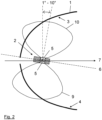
- Figure 1 shows a schematic front view of a H4 headlamp reflector 1 in which a LED lamp unit 2 according to an embodiment of the present invention is mounted.
- the reflector 1 comprises a low beam reflector portion 3 and a high beam reflector portion 4 separated by the dashed lines in the figure.
- the LED light sources 5 of the LED lamp unit arranged on two opposing sides of a support member are schematically indicated in the figure.
- the two opposing half-spaces, into which the LED light sources 5 emit, are separated by the indicated plane 6.
- this plane 6 is tilted by an angle of between 5° to 30° to the horizontal plane around the optical axis 7 of the headlamp.
- This optical axis 7 extends perpendicular to the paper plane at the center of the reflector 1.
- Additional glare shields 8 are arranged on the lamp unit in order to ensure that the light beam 9 emitted from the LEDs at the lower side of the support member only impinges on the high beam reflector portion 4 and that light beam 10 emitted from the LEDs arranged at the upper side of the support member only impinges on the low beam reflector portion 3.
- the LED lamp unit 2 is additionally tilted by an angle of between 1° and 10° downwards against the horizontal plane including the optical axis 7. This significantly increases the intensity in the distance area in such a H4 headlamp.
- the proposed LED H4 retrofit lamp unit preferably comprises in maximum six LEDs, each having an emission area of approx. 1 ⁇ 1mm 2 , for generating the low beam pattern and in maximum six LEDs with the same emission area for generating the high beam pattern.
- Figure 3a shows a preferred low beam LED configuration having four LEDs 5 arranged in a line and occupying an area of 5 mm in length and 1 mm in width.
- Figure 3 b shows a preferred high beam LED configuration with a total of six LEDs 5 in two rows. The six LEDs occupy an area of 4 mm x 2 mm as can be recognized in the figure.
- FIG 4 shows an example of a lamp unit according to the present invention in a sectional view.
- the LED lamp unit 1 comprises the LEDs 5 mounted back to back on a thin metal plate representing the support member 11.
- the LEDs 5 emit in opposite directions or half-spaces.
- Two heat sinks 12, 13 are mounted perpendicular to the metal plate on opposite sides at the edges of the metal plate.
- the heat sinks 12, 13 comprise several cooling fins 14 extending between the LEDs 5 and the fans 15, 16 mounted at the back sides of the heat sinks 12, 13. Gaps 17 formed between the cooling fins 14 of the heat sinks 12, 13 are opened towards the fans 15, 16 and towards the LED light sources 5. With such an arrangement, a maximum cooling effect can be achieved by blowing air in opposite directions toward the LEDs 5.
- the heat sinks 12, 13 are tapered at their ends facing the LEDs 5 in order to achieve the emission of the LED light in a large solid angle.
- the electrical connections to the LEDs and the fans and the corresponding electrical connector socket are not shown in the figure.
- This electrical connector socket is arranged on one side of the lamp unit and is designed to fit in a corresponding H4 lamp holder and to achieve the desired tilting of the metal plate forming the support member 11 with respect to the horizontal plane when mounted in the lamp holder.
Landscapes
- Engineering & Computer Science (AREA)
- General Engineering & Computer Science (AREA)
- Physics & Mathematics (AREA)
- Microelectronics & Electronic Packaging (AREA)
- Optics & Photonics (AREA)
- Mathematical Physics (AREA)
- Non-Portable Lighting Devices Or Systems Thereof (AREA)
- Arrangement Of Elements, Cooling, Sealing, Or The Like Of Lighting Devices (AREA)
- Led Device Packages (AREA)
Description
- The present invention relates to a LED lamp unit comprising at least two LED light sources arranged on two opposing sides of a support member to emit in opposed half-spaces, a heat sink in thermal contact with said support member of the LED light sources and an electrical connector socket for electrically connecting the LED light sources. The invention also relates to a headlamp at least comprising a reflector, a H4 lamp holder and such a LED lamp unit.
- Automotive H4 halogen bulbs provide low and high beam from a single light source having two filaments. The corresponding headlamp is designed to provide a low beam reflector and a high beam reflector as well as the corresponding lamp holder for mounting the H4 bulb in the appropriate position and orientation. Due to the cost efficient H4 headlamp concept this technology is still the most popular light sources technology for low and medium car segments.
- The main drawback of halogen bulb technology is its inefficiency and limited lifetime. Additionally it is often extremely difficult to exchange the bulb without the help of a garage. In order to provide an acceptable light distribution which is compliant to the corresponding legal regulations a H4 bulb requires a power of 60W to generate a flux of 1000 lumen. The corresponding typical lifetime is on the order of 500 hours.
- On the other hand LED technology is much more energy efficient and provides a lifetime which is equal to a car life. A few years ago the first Full-LED-headlamps were launched mainly in the high end car segments. All these headlamps had to be equipped with optics which are optimized to the corresponding LED light emission pattern in order to fulfill the legal beam pattern requirement.
- It is desirable to provide so called LED retrofits which may simply replace the known H4 halogen bulbs in an automotive headlamp without any change in the design of the optics of the headlamp. At present LED retrofits for nearly every automotive halogen bulb type a available in the market which fit into the corresponding lamp holder of the halogen headlamps. These commercially available LED retrofits however, at least in case of H4 LED retrofits, provide excessive glare and only 10% of the illumination values required for a legal beam pattern.
- These known H4 retrofit LED lamps do not fulfill the legal beam pattern requirement without a change of the optics of the headlamp.
- Instead, for providing a true legal H4 retrofit,
DE 10 2007 044 628 A1 - It is an object of the present invention to provide a LED H4 retrofit lamp unit which fulfills the legal beam pattern requirement without any design change of the optics of the headlamp.
- The object is achieved with the LED lamp unit according to
claim 1.Claim 7 relates to a corresponding headlamp including a LED lamp unit. Advantageous embodiments of the LED lamp unit and headlamp are subject matter of the dependent claims or are disclosed in the subsequent portions of the description and preferred embodiment. - The proposed LED lamp unit at least comprises two LED light sources arranged on two opposing sides of a support member to emit in opposed half-spaces, a heat sink in thermal contact with the support member of the LED light sources and an electrical connector socket for electrically connecting the LED light sources. Preferably the heat sink is also in thermal contact with connector socket. Furthermore, one or several fans may be attached to the heat sink. The electrical connector socket for electrical connecting the LED light sources is designed to fit in a lamp holder of a H4 headlamp. In order to fulfill the legal beam pattern requirements when mounted in such a headlamp, the electrical connector socket is designed such that the plane separating the opposed half-spaces is tilted around the optical axis of the headlamp or headlamp reflector by an angle of between 5° and 30° against the horizontal plane when the connector socket is correctly mounted in the lamp holder.
- By this tilting of the plane separating the two opposed half-spaces against the horizontal in a headlamp, the legal beam pattern is achieved without any further adaptation of the optics of the headlamp. The plane separating the two half-spaces is the symmetry plane between the LED light sources mounted on one side of the support member and the LED light sources mounted on the other, opposing side of the support member. In case of a plate-like support member, this plane coincides with the symmetry plane of the plate-like support member.
- In order to avoid glare, appropriate glare shields may be arranged on the LED lamp unit. Such glare shields then avoid that light emitted from the LED light sources on the lower side of the support member impinges on the low beam reflector portion and that light emitted from the LED light sources arranged on the upper side of the support member impinges on the high beam reflector portion. The upper and lower sides of the support member refer to the position of the two sides of the support member when the lamp unit is correctly mounted in the headlamp.
- In a preferred embodiment, the electrical connector socket is designed such that the plane separating the opposed half-spaces is additionally tilted downwards from the horizontal plane including the optical axis of the headlamp by an angle of between 1° and 10° when the connector socket is mounted in the lamp holder. The tilting direction is such that the plane intersects the emission face of the headlamp at a position lower than the optical axis. With such an additional tilting it has been discovered that the light intensity in the distance area, i.e. in a distance of between 20 m to 80 m from the headlamp, in most known H4 headlamps in increased significantly.
- In order to achieve the above tilting of the plane separating the opposed half-spaces, the lamp socket has to be appropriately oriented in the lamp unit with respect to the support member carrying the LED light sources. Since the lamp socket can only be mounted in the lamp holder of a H4 headlamp in one single defined position and orientation, the tilting is then automatically achieved when correctly mounting the LED lamp unit in the headlamp.
- In the proposed LED lamp unit, in the following also called LED H4 retrofit lamp unit, preferably in maximum 6 LEDs for generating the low beam pattern are arranged on the upper side of the support member and in maximum 6 LEDs for generating the high beam pattern are arranged at the lower side of the support member. In a preferred configuration an array of LEDs forms the low beam configuration and another array of LEDs forms the high beam configuration. The number of LEDs in each array may vary.
- The corresponding headlamp including such a LED lamp unit comprises at least a reflector, a H4 lamp holder and the LED lamp unit. Although the LED lamp unit is according to the invention designed such that the above tilting angle is achieved when mounting the LED lamp unit in the H4 lamp holder of a H4 headlamp, it would also be possible (not according to the invention) to adapt the lamp holder in such a headlamp to achieve the desired tilting angle with a LED lamp unit which is not specially designed to achieve such an angle. This means that the LED lamp unit at least comprises two LED light sources arranged on two opposing sides of a support member to emit in opposed half-spaces, a heat sink in thermal contact with the support member of the LED light sources and an electrical connector socket for electrical connecting the LED light sources which fits in the H4 lamp holder. The electrical connector socket in such a case would be designed without taking care of any tilting angle, e.g. without any tilting when mounted in a conventional headlamp. In such a case, the headlamp itself would be adapted by appropriately orienting the lamp holder in order to achieve the above tilting angle(s) when the LED lamp unit is mounted in the holder. Such an example however requires a modification of the known H4 headlamps with respect to the spatial orientation of the lamp holder.
- The construction of the LED lamp unit with LED light sources arranged on two opposing sides of a support member allows an illumination into both opposing half-spheres similar to the illumination of a H4 halogen bulb. With the arrangement of the heat sink on the side opposite to the electrical connection socket according to an embodiment of the invention, an elongated shape and dimensions similar to those of known H4 bulbs for automotive lamps are achieved. In a preferred embodiment, two separate heat sinks are arranged at two opposing edges of the support member in thermal contact with the support member. One of these heat sinks is thus arranged between the electrical connector socket and the support member. The heat sinks may comprise several cooling fins. In order to improve the cooling power, also an electrically operated fan can be arranged at one or both of the heat sinks such the fan generates a flow of cooling gas, in particular cooling air, through gaps between the cooling fins of the heat sink towards the LED light sources. Preferably the whole LED lamp unit has a dimension in a longitudinal direction, i.e. the direction between the connector socket and the heat sink, of less than 80 mm, more preferably of ≤ 50 mm, and a diameter perpendicular to this longitudinal direction of less than 20 mm, more preferably ≤ 15 mm.
- This and another aspects of the invention will be apparent from and elucidated with reference to the embodiment described herein after. In the drawings:
-
Fig. 1 shows a front view of a H4 reflector in which the proposed LED lamp unit according to an embodiment of the invention is mounted; -
Fig. 2 shows a side view of the H4 reflector offigure 1 with the mounted LED lamp unit; -
Fig. 3 shows an exemplary arrangement of the LED light sources on the lower side of the support member (3a) and of the LED light sources on the upper side of the support member (3b); and -
Fig. 4 shows a sectional view of an example of the LED lamp unit according to the invention. -
Figure 1 shows a schematic front view of aH4 headlamp reflector 1 in which aLED lamp unit 2 according to an embodiment of the present invention is mounted. Thereflector 1 comprises a lowbeam reflector portion 3 and a highbeam reflector portion 4 separated by the dashed lines in the figure. TheLED light sources 5 of the LED lamp unit arranged on two opposing sides of a support member are schematically indicated in the figure. The two opposing half-spaces, into which theLED light sources 5 emit, are separated by the indicatedplane 6. As can be seen from the figure, thisplane 6 is tilted by an angle of between 5° to 30° to the horizontal plane around theoptical axis 7 of the headlamp. Thisoptical axis 7 extends perpendicular to the paper plane at the center of thereflector 1.Additional glare shields 8 are arranged on the lamp unit in order to ensure that thelight beam 9 emitted from the LEDs at the lower side of the support member only impinges on the highbeam reflector portion 4 and thatlight beam 10 emitted from the LEDs arranged at the upper side of the support member only impinges on the lowbeam reflector portion 3. - As can be seen from the side view shown in
figure 2 , theLED lamp unit 2 is additionally tilted by an angle of between 1° and 10° downwards against the horizontal plane including theoptical axis 7. This significantly increases the intensity in the distance area in such a H4 headlamp. - The proposed LED H4 retrofit lamp unit preferably comprises in maximum six LEDs, each having an emission area of approx. 1×1mm2, for generating the low beam pattern and in maximum six LEDs with the same emission area for generating the high beam pattern. Figure 3a shows a preferred low beam LED configuration having four
LEDs 5 arranged in a line and occupying an area of 5 mm in length and 1 mm in width. Figure 3 b shows a preferred high beam LED configuration with a total of sixLEDs 5 in two rows. The six LEDs occupy an area of 4 mm x 2 mm as can be recognized in the figure. -
Figure 4 shows an example of a lamp unit according to the present invention in a sectional view. In this example theLED lamp unit 1 comprises theLEDs 5 mounted back to back on a thin metal plate representing thesupport member 11. TheLEDs 5 emit in opposite directions or half-spaces. Twoheat sinks several cooling fins 14 extending between theLEDs 5 and thefans Gaps 17 formed between the coolingfins 14 of the heat sinks 12, 13 are opened towards thefans LED light sources 5. With such an arrangement, a maximum cooling effect can be achieved by blowing air in opposite directions toward theLEDs 5. The heat sinks 12, 13 are tapered at their ends facing theLEDs 5 in order to achieve the emission of the LED light in a large solid angle. The electrical connections to the LEDs and the fans and the corresponding electrical connector socket are not shown in the figure. This electrical connector socket is arranged on one side of the lamp unit and is designed to fit in a corresponding H4 lamp holder and to achieve the desired tilting of the metal plate forming thesupport member 11 with respect to the horizontal plane when mounted in the lamp holder. - While the invention has been illustrated and described in detail in the drawings and forgoing description, such illustration and description are to be considered illustrative or exemplary and not restrictive. The invention is not limited to the disclosed embodiments. Only the appended claims are limiting the invention. Other variations to the disclosed embodiments can be understood and effected by those skilled in the art in practicing the claimed invention, from a study of the drawings, the disclosure, and the appended claims. The heat sinks may also be formed different than in the figure. Also the design of the lamp unit may substantially deviate from the example of
figure 4 . In the claims, the word "comprising" does not exclude other elements or steps and the indefinite article "a" or "an" does not exclude a plurality. The mere fact that certain measures are recited in mutually different dependent claims does not indicate that a combination of these measures cannot be used to advantage. In particular, the features ofclaims 1 to 5 can be freely combined. Any reference signs in the claims should not be construed as limiting the scope of the claims. -
- 1
- headlamp reflector
- 2
- LED lamp unit
- 3
- low beam reflector portion
- 4
- high beam reflector portion
- 5
- LEDs
- 6
- plane separating opposing half-spaces
- 7
- optical axis
- 8
- glare shield
- 9
- light beam
- 10
- light beam
- 11
- support member
- 12
- heat sink
- 13
- heat sink
- 14
- cooling fin
- 15
- fan
- 16
- fan
- 17
- gap
Claims (8)
- A LED retrofit lamp unit suitable for use in a H4 headlamp for providing a low and a high beam, at least comprising- two LED light sources (5) arranged on two opposing sides of a support member (11) to emit in opposed half-spaces,- a heat sink (12, 13) in thermal contact with said support member (11) of the LED light sources (5), and- an electrical connector socket for mounting the LED retrofit lamp unit in a lamp holder of the H4 headlamp,characterized in that,the electrical connector socket is designed such that when the LED retrofit lamp unit is correctly mounted in the H4 headlamp, a symmetry plane (6) between the two light sources (5) separating the opposed half-spaces is tilted around an optical axis (7) of the H4 headlamp by an angle of between 5° and 30° against a horizontal plane,wherein the tilting angle of between 5° and 30° is achieved due to a tilted orientation between the electrical connector socket and the support member (11) of the LED retrofit lamp unit.
- The LED retrofit lamp unit according to claim 1,wherein said electrical connector socket is designed and arranged such that, when the LED retrofit lamp unit is correctly mounted in the H4 headlamp, the plane (6) separating the opposed half-spaces is additionally tilted downwards from the horizontal plane including the optical axis (7) of the H4 headlamp by an angle of between 1° and 10°,wherein the tilting angle of between 1° and 10° is achieved due to a tilted orientation between the electrical connector socket and the support member (11) of the LED retrofit lamp unit.
- The LED retrofit lamp unit according to claim 1 or 2,
wherein, as seen when the LED retrofit lamp unit is correctly mounted in the H4 headlamp, an array of LED light sources (5) is arranged on the upper of the two opposing sides of the support member (11) and another array of LED light sources (5) is arranged on the lower of the two opposing sides of the support member (11). - The LED retrofit lamp unit according to claim 1 or 2,
comprising glare shields (8) to avoid, when the LED retrofit lamp unit is correctly mounted in the H4 headlamp- impinging of light of the LED light sources (5) arranged on the lower of the two opposing sides of the support member (11) on a low beam reflector portion of a reflector of the H4 headlamp, and/or- impinging of light of the LED light sources (5) arranged on the upper of the two opposing sides of the support member (11) on a high beam reflector portion of the reflector of the H4 headlamp. - The LED retrofit lamp unit according to claim 1 or 2,
wherein said support member (11) is arranged between at least a portion of said heat sink (13) and said electrical connector socket. - The LED retrofit lamp unit according to claim 5,
wherein a second heat sink (12) is arranged in thermal contact with the support member (11) between the electrical connector socket and the support member (11). - A headlamp for providing a low and a high beam at least comprising a reflector (1), a H4 lamp holder and a LED retrofit lamp unit (2), said LED retrofit lamp unit (2) at least comprising- two LED light sources (5) arranged on two opposing sides of a support member (11) to emit in opposed half-spaces,- a heat sink (12, 13) in thermal contact with said support member (11) of the LED light sources (5), and- an electrical connector socket for electrically connecting the LED light sources (5),which LED retrofit lamp unit (2) fits in said H4 lamp holder,characterized in thatsaid LED retrofit lamp unit (2) is correctly mounted in said lamp holder such that a symmetry plane (6) between the two light sources (5) separating the opposed half-spaces is tilted around an optical axis (7) of the headlamp by an angle of between 5° and 30° against a horizontal plane such that the legal beam pattern is achieved without anyfurther adaptation of the optics of the headlamp,wherein the tilting angle of between 5° and 30° is achieved due to a tilted orientation between the electrical connector socket and the support member (11) of the LED retrofit lamp unit (2).
- The headlamp according to claim 7,wherein said LED retrofit lamp unit (2) is correctly mounted in said lamp holder such that the plane (6) separating the opposed half-spaces is additionally tilted downwards from the horizontal plane including the optical axis (7) of the headlamp by an angle of between 1° and 10°,wherein the tilting angle of between 1° and 10° is achieved due to a tilted orientation between the electrical connector socket and the support member (11) of the LED retrofit lamp unit (2).
Priority Applications (1)
| Application Number | Priority Date | Filing Date | Title |
|---|---|---|---|
| EP14732541.9A EP3014170B1 (en) | 2013-06-27 | 2014-06-18 | Led h4 retrofit lamp unit |
Applications Claiming Priority (3)
| Application Number | Priority Date | Filing Date | Title |
|---|---|---|---|
| EP13173998 | 2013-06-27 | ||
| PCT/EP2014/062782 WO2014206821A1 (en) | 2013-06-27 | 2014-06-18 | Led h4 retrofit lamp unit |
| EP14732541.9A EP3014170B1 (en) | 2013-06-27 | 2014-06-18 | Led h4 retrofit lamp unit |
Publications (2)
| Publication Number | Publication Date |
|---|---|
| EP3014170A1 EP3014170A1 (en) | 2016-05-04 |
| EP3014170B1 true EP3014170B1 (en) | 2023-05-03 |
Family
ID=48700371
Family Applications (1)
| Application Number | Title | Priority Date | Filing Date |
|---|---|---|---|
| EP14732541.9A Active EP3014170B1 (en) | 2013-06-27 | 2014-06-18 | Led h4 retrofit lamp unit |
Country Status (6)
| Country | Link |
|---|---|
| US (1) | US9857043B2 (en) |
| EP (1) | EP3014170B1 (en) |
| JP (1) | JP6272470B2 (en) |
| CN (1) | CN105308386B (en) |
| BR (1) | BR112015032626B1 (en) |
| WO (1) | WO2014206821A1 (en) |
Families Citing this family (3)
| Publication number | Priority date | Publication date | Assignee | Title |
|---|---|---|---|---|
| TWI572811B (en) * | 2016-08-15 | 2017-03-01 | Chun-Hsien Kuo | To light bulb type light bulb headlights |
| US10415787B2 (en) | 2018-01-11 | 2019-09-17 | Osram Sylvania Inc. | Vehicle LED lamp having recirculating air channels |
| EP3907428B1 (en) * | 2020-05-07 | 2023-09-27 | Lumileds LLC | Retrofit lighting device with improved thermal properties |
Citations (2)
| Publication number | Priority date | Publication date | Assignee | Title |
|---|---|---|---|---|
| US4225903A (en) * | 1977-05-10 | 1980-09-30 | Bayerische Motoren Werke Aktiengesellschaft | Motor vehicle headlight for low and high beams |
| DE19616037A1 (en) * | 1996-04-23 | 1997-10-30 | Bosch Gmbh Robert | Vehicle headlamp with dipped and beam |
Family Cites Families (7)
| Publication number | Priority date | Publication date | Assignee | Title |
|---|---|---|---|---|
| JP2002109915A (en) | 2000-09-27 | 2002-04-12 | Koito Mfg Co Ltd | Vehicle headlights |
| CN200972620Y (en) * | 2006-11-23 | 2007-11-07 | 番禺得意精密电子工业有限公司 | Back plate |
| JP4556942B2 (en) * | 2006-11-27 | 2010-10-06 | 市光工業株式会社 | Vehicle headlamp |
| US7824076B2 (en) | 2007-05-31 | 2010-11-02 | Koester George H | LED reflector lamp |
| WO2009037053A1 (en) * | 2007-09-19 | 2009-03-26 | Osram Gesellschaft mit beschränkter Haftung | Headlamp and its use |
| DE102007044628A1 (en) * | 2007-09-19 | 2009-04-02 | Osram Gesellschaft mit beschränkter Haftung | Headlamp i.e. H4 retrofit lamp, for use as e.g. gas-discharge lamp, in motor vehicle, has lamp base and light emission predefined by international standards with respect to distance and position in relation to reference plane of base |
| DE102011007123B4 (en) * | 2011-04-11 | 2022-02-17 | Osram Gmbh | Semiconductor incandescent lamp retrofit lamp |
-
2014
- 2014-06-18 EP EP14732541.9A patent/EP3014170B1/en active Active
- 2014-06-18 BR BR112015032626-9A patent/BR112015032626B1/en not_active IP Right Cessation
- 2014-06-18 JP JP2016522394A patent/JP6272470B2/en active Active
- 2014-06-18 WO PCT/EP2014/062782 patent/WO2014206821A1/en not_active Ceased
- 2014-06-18 US US14/901,061 patent/US9857043B2/en active Active
- 2014-06-18 CN CN201480036596.9A patent/CN105308386B/en active Active
Patent Citations (2)
| Publication number | Priority date | Publication date | Assignee | Title |
|---|---|---|---|---|
| US4225903A (en) * | 1977-05-10 | 1980-09-30 | Bayerische Motoren Werke Aktiengesellschaft | Motor vehicle headlight for low and high beams |
| DE19616037A1 (en) * | 1996-04-23 | 1997-10-30 | Bosch Gmbh Robert | Vehicle headlamp with dipped and beam |
Also Published As
| Publication number | Publication date |
|---|---|
| CN105308386B (en) | 2019-03-29 |
| JP2016527669A (en) | 2016-09-08 |
| EP3014170A1 (en) | 2016-05-04 |
| US9857043B2 (en) | 2018-01-02 |
| BR112015032626A2 (en) | 2021-08-17 |
| CN105308386A (en) | 2016-02-03 |
| WO2014206821A1 (en) | 2014-12-31 |
| US20160169466A1 (en) | 2016-06-16 |
| JP6272470B2 (en) | 2018-01-31 |
| BR112015032626B1 (en) | 2021-11-30 |
Similar Documents
| Publication | Publication Date | Title |
|---|---|---|
| US10415762B2 (en) | LED lamp unit, in particular for automotive lamps | |
| EP3169930B1 (en) | Retrofit lamp for automotive headlights | |
| JP7116076B2 (en) | LED lamp | |
| US9964260B2 (en) | LED lighting device with improved light distribution | |
| US20170234521A1 (en) | Omnidirectional light emission led lamp | |
| US9857043B2 (en) | LED H4 retrofit lamp unit | |
| CN106855187B (en) | A kind of LED light device | |
| KR20130027759A (en) | Led headlamp of vehicle | |
| JP3097333U (en) | LED lamp | |
| JP3173289U (en) | Spotlight | |
| CN111288309A (en) | LED bulb lamp connecting heat dissipation lamp holder | |
| TWM504024U (en) | Light-bulb | |
| TW201718290A (en) | Light device | |
| TWM500064U (en) | LED lamp having triple-facet structure for motocycle use | |
| CN105782847A (en) | Substitutional LED automotive headlight light source |
Legal Events
| Date | Code | Title | Description |
|---|---|---|---|
| PUAI | Public reference made under article 153(3) epc to a published international application that has entered the european phase |
Free format text: ORIGINAL CODE: 0009012 |
|
| 17P | Request for examination filed |
Effective date: 20160127 |
|
| AK | Designated contracting states |
Kind code of ref document: A1 Designated state(s): AL AT BE BG CH CY CZ DE DK EE ES FI FR GB GR HR HU IE IS IT LI LT LU LV MC MK MT NL NO PL PT RO RS SE SI SK SM TR |
|
| AX | Request for extension of the european patent |
Extension state: BA ME |
|
| DAX | Request for extension of the european patent (deleted) | ||
| RAP1 | Party data changed (applicant data changed or rights of an application transferred) |
Owner name: LUMILEDS HOLDING B.V. |
|
| RAP1 | Party data changed (applicant data changed or rights of an application transferred) |
Owner name: LUMILEDS HOLDING B.V. |
|
| STAA | Information on the status of an ep patent application or granted ep patent |
Free format text: STATUS: EXAMINATION IS IN PROGRESS |
|
| 17Q | First examination report despatched |
Effective date: 20200626 |
|
| RAP1 | Party data changed (applicant data changed or rights of an application transferred) |
Owner name: LUMILEDS LLC |
|
| REG | Reference to a national code |
Ref country code: DE Ref legal event code: R079 Ref document number: 602014086830 Country of ref document: DE Free format text: PREVIOUS MAIN CLASS: F21S0008100000 Ipc: F21S0041147000 |
|
| RIC1 | Information provided on ipc code assigned before grant |
Ipc: F21W 102/13 20180101ALN20221013BHEP Ipc: F21K 9/232 20160101ALI20221013BHEP Ipc: F21S 45/47 20180101ALI20221013BHEP Ipc: F21S 45/43 20180101ALI20221013BHEP Ipc: F21S 41/153 20180101ALI20221013BHEP Ipc: F21S 41/147 20180101AFI20221013BHEP |
|
| GRAP | Despatch of communication of intention to grant a patent |
Free format text: ORIGINAL CODE: EPIDOSNIGR1 |
|
| STAA | Information on the status of an ep patent application or granted ep patent |
Free format text: STATUS: GRANT OF PATENT IS INTENDED |
|
| INTG | Intention to grant announced |
Effective date: 20221124 |
|
| GRAS | Grant fee paid |
Free format text: ORIGINAL CODE: EPIDOSNIGR3 |
|
| GRAA | (expected) grant |
Free format text: ORIGINAL CODE: 0009210 |
|
| STAA | Information on the status of an ep patent application or granted ep patent |
Free format text: STATUS: THE PATENT HAS BEEN GRANTED |
|
| AK | Designated contracting states |
Kind code of ref document: B1 Designated state(s): AL AT BE BG CH CY CZ DE DK EE ES FI FR GB GR HR HU IE IS IT LI LT LU LV MC MK MT NL NO PL PT RO RS SE SI SK SM TR |
|
| REG | Reference to a national code |
Ref country code: GB Ref legal event code: FG4D |
|
| REG | Reference to a national code |
Ref country code: DE Ref legal event code: R096 Ref document number: 602014086830 Country of ref document: DE |
|
| REG | Reference to a national code |
Ref country code: AT Ref legal event code: REF Ref document number: 1564872 Country of ref document: AT Kind code of ref document: T Effective date: 20230515 Ref country code: CH Ref legal event code: EP |
|
| REG | Reference to a national code |
Ref country code: IE Ref legal event code: FG4D |
|
| REG | Reference to a national code |
Ref country code: LT Ref legal event code: MG9D |
|
| REG | Reference to a national code |
Ref country code: NL Ref legal event code: MP Effective date: 20230503 |
|
| REG | Reference to a national code |
Ref country code: AT Ref legal event code: MK05 Ref document number: 1564872 Country of ref document: AT Kind code of ref document: T Effective date: 20230503 |
|
| PG25 | Lapsed in a contracting state [announced via postgrant information from national office to epo] |
Ref country code: SE Free format text: LAPSE BECAUSE OF FAILURE TO SUBMIT A TRANSLATION OF THE DESCRIPTION OR TO PAY THE FEE WITHIN THE PRESCRIBED TIME-LIMIT Effective date: 20230503 Ref country code: PT Free format text: LAPSE BECAUSE OF FAILURE TO SUBMIT A TRANSLATION OF THE DESCRIPTION OR TO PAY THE FEE WITHIN THE PRESCRIBED TIME-LIMIT Effective date: 20230904 Ref country code: NO Free format text: LAPSE BECAUSE OF FAILURE TO SUBMIT A TRANSLATION OF THE DESCRIPTION OR TO PAY THE FEE WITHIN THE PRESCRIBED TIME-LIMIT Effective date: 20230803 Ref country code: NL Free format text: LAPSE BECAUSE OF FAILURE TO SUBMIT A TRANSLATION OF THE DESCRIPTION OR TO PAY THE FEE WITHIN THE PRESCRIBED TIME-LIMIT Effective date: 20230503 Ref country code: ES Free format text: LAPSE BECAUSE OF FAILURE TO SUBMIT A TRANSLATION OF THE DESCRIPTION OR TO PAY THE FEE WITHIN THE PRESCRIBED TIME-LIMIT Effective date: 20230503 Ref country code: AT Free format text: LAPSE BECAUSE OF FAILURE TO SUBMIT A TRANSLATION OF THE DESCRIPTION OR TO PAY THE FEE WITHIN THE PRESCRIBED TIME-LIMIT Effective date: 20230503 |
|
| PG25 | Lapsed in a contracting state [announced via postgrant information from national office to epo] |
Ref country code: RS Free format text: LAPSE BECAUSE OF FAILURE TO SUBMIT A TRANSLATION OF THE DESCRIPTION OR TO PAY THE FEE WITHIN THE PRESCRIBED TIME-LIMIT Effective date: 20230503 Ref country code: PL Free format text: LAPSE BECAUSE OF FAILURE TO SUBMIT A TRANSLATION OF THE DESCRIPTION OR TO PAY THE FEE WITHIN THE PRESCRIBED TIME-LIMIT Effective date: 20230503 Ref country code: LV Free format text: LAPSE BECAUSE OF FAILURE TO SUBMIT A TRANSLATION OF THE DESCRIPTION OR TO PAY THE FEE WITHIN THE PRESCRIBED TIME-LIMIT Effective date: 20230503 Ref country code: LT Free format text: LAPSE BECAUSE OF FAILURE TO SUBMIT A TRANSLATION OF THE DESCRIPTION OR TO PAY THE FEE WITHIN THE PRESCRIBED TIME-LIMIT Effective date: 20230503 Ref country code: IS Free format text: LAPSE BECAUSE OF FAILURE TO SUBMIT A TRANSLATION OF THE DESCRIPTION OR TO PAY THE FEE WITHIN THE PRESCRIBED TIME-LIMIT Effective date: 20230903 Ref country code: HR Free format text: LAPSE BECAUSE OF FAILURE TO SUBMIT A TRANSLATION OF THE DESCRIPTION OR TO PAY THE FEE WITHIN THE PRESCRIBED TIME-LIMIT Effective date: 20230503 Ref country code: GR Free format text: LAPSE BECAUSE OF FAILURE TO SUBMIT A TRANSLATION OF THE DESCRIPTION OR TO PAY THE FEE WITHIN THE PRESCRIBED TIME-LIMIT Effective date: 20230804 |
|
| PG25 | Lapsed in a contracting state [announced via postgrant information from national office to epo] |
Ref country code: FI Free format text: LAPSE BECAUSE OF FAILURE TO SUBMIT A TRANSLATION OF THE DESCRIPTION OR TO PAY THE FEE WITHIN THE PRESCRIBED TIME-LIMIT Effective date: 20230503 |
|
| PG25 | Lapsed in a contracting state [announced via postgrant information from national office to epo] |
Ref country code: SK Free format text: LAPSE BECAUSE OF FAILURE TO SUBMIT A TRANSLATION OF THE DESCRIPTION OR TO PAY THE FEE WITHIN THE PRESCRIBED TIME-LIMIT Effective date: 20230503 |
|
| PG25 | Lapsed in a contracting state [announced via postgrant information from national office to epo] |
Ref country code: SM Free format text: LAPSE BECAUSE OF FAILURE TO SUBMIT A TRANSLATION OF THE DESCRIPTION OR TO PAY THE FEE WITHIN THE PRESCRIBED TIME-LIMIT Effective date: 20230503 Ref country code: SK Free format text: LAPSE BECAUSE OF FAILURE TO SUBMIT A TRANSLATION OF THE DESCRIPTION OR TO PAY THE FEE WITHIN THE PRESCRIBED TIME-LIMIT Effective date: 20230503 Ref country code: RO Free format text: LAPSE BECAUSE OF FAILURE TO SUBMIT A TRANSLATION OF THE DESCRIPTION OR TO PAY THE FEE WITHIN THE PRESCRIBED TIME-LIMIT Effective date: 20230503 Ref country code: EE Free format text: LAPSE BECAUSE OF FAILURE TO SUBMIT A TRANSLATION OF THE DESCRIPTION OR TO PAY THE FEE WITHIN THE PRESCRIBED TIME-LIMIT Effective date: 20230503 Ref country code: DK Free format text: LAPSE BECAUSE OF FAILURE TO SUBMIT A TRANSLATION OF THE DESCRIPTION OR TO PAY THE FEE WITHIN THE PRESCRIBED TIME-LIMIT Effective date: 20230503 Ref country code: CZ Free format text: LAPSE BECAUSE OF FAILURE TO SUBMIT A TRANSLATION OF THE DESCRIPTION OR TO PAY THE FEE WITHIN THE PRESCRIBED TIME-LIMIT Effective date: 20230503 |
|
| REG | Reference to a national code |
Ref country code: CH Ref legal event code: PL |
|
| REG | Reference to a national code |
Ref country code: DE Ref legal event code: R097 Ref document number: 602014086830 Country of ref document: DE |
|
| REG | Reference to a national code |
Ref country code: BE Ref legal event code: MM Effective date: 20230630 |
|
| PG25 | Lapsed in a contracting state [announced via postgrant information from national office to epo] |
Ref country code: MC Free format text: LAPSE BECAUSE OF FAILURE TO SUBMIT A TRANSLATION OF THE DESCRIPTION OR TO PAY THE FEE WITHIN THE PRESCRIBED TIME-LIMIT Effective date: 20230503 |
|
| PG25 | Lapsed in a contracting state [announced via postgrant information from national office to epo] |
Ref country code: MC Free format text: LAPSE BECAUSE OF FAILURE TO SUBMIT A TRANSLATION OF THE DESCRIPTION OR TO PAY THE FEE WITHIN THE PRESCRIBED TIME-LIMIT Effective date: 20230503 |
|
| PG25 | Lapsed in a contracting state [announced via postgrant information from national office to epo] |
Ref country code: LU Free format text: LAPSE BECAUSE OF NON-PAYMENT OF DUE FEES Effective date: 20230618 |
|
| PLBE | No opposition filed within time limit |
Free format text: ORIGINAL CODE: 0009261 |
|
| STAA | Information on the status of an ep patent application or granted ep patent |
Free format text: STATUS: NO OPPOSITION FILED WITHIN TIME LIMIT |
|
| REG | Reference to a national code |
Ref country code: IE Ref legal event code: MM4A |
|
| PG25 | Lapsed in a contracting state [announced via postgrant information from national office to epo] |
Ref country code: LU Free format text: LAPSE BECAUSE OF NON-PAYMENT OF DUE FEES Effective date: 20230618 |
|
| 26N | No opposition filed |
Effective date: 20240206 |
|
| PG25 | Lapsed in a contracting state [announced via postgrant information from national office to epo] |
Ref country code: IE Free format text: LAPSE BECAUSE OF NON-PAYMENT OF DUE FEES Effective date: 20230618 |
|
| PG25 | Lapsed in a contracting state [announced via postgrant information from national office to epo] |
Ref country code: IE Free format text: LAPSE BECAUSE OF NON-PAYMENT OF DUE FEES Effective date: 20230618 Ref country code: CH Free format text: LAPSE BECAUSE OF NON-PAYMENT OF DUE FEES Effective date: 20230630 |
|
| PG25 | Lapsed in a contracting state [announced via postgrant information from national office to epo] |
Ref country code: SI Free format text: LAPSE BECAUSE OF FAILURE TO SUBMIT A TRANSLATION OF THE DESCRIPTION OR TO PAY THE FEE WITHIN THE PRESCRIBED TIME-LIMIT Effective date: 20230503 |
|
| PG25 | Lapsed in a contracting state [announced via postgrant information from national office to epo] |
Ref country code: SI Free format text: LAPSE BECAUSE OF FAILURE TO SUBMIT A TRANSLATION OF THE DESCRIPTION OR TO PAY THE FEE WITHIN THE PRESCRIBED TIME-LIMIT Effective date: 20230503 Ref country code: IT Free format text: LAPSE BECAUSE OF FAILURE TO SUBMIT A TRANSLATION OF THE DESCRIPTION OR TO PAY THE FEE WITHIN THE PRESCRIBED TIME-LIMIT Effective date: 20230503 Ref country code: BE Free format text: LAPSE BECAUSE OF NON-PAYMENT OF DUE FEES Effective date: 20230630 |
|
| PG25 | Lapsed in a contracting state [announced via postgrant information from national office to epo] |
Ref country code: BG Free format text: LAPSE BECAUSE OF FAILURE TO SUBMIT A TRANSLATION OF THE DESCRIPTION OR TO PAY THE FEE WITHIN THE PRESCRIBED TIME-LIMIT Effective date: 20230503 |
|
| PG25 | Lapsed in a contracting state [announced via postgrant information from national office to epo] |
Ref country code: BG Free format text: LAPSE BECAUSE OF FAILURE TO SUBMIT A TRANSLATION OF THE DESCRIPTION OR TO PAY THE FEE WITHIN THE PRESCRIBED TIME-LIMIT Effective date: 20230503 |
|
| PGFP | Annual fee paid to national office [announced via postgrant information from national office to epo] |
Ref country code: DE Payment date: 20250627 Year of fee payment: 12 |
|
| PGFP | Annual fee paid to national office [announced via postgrant information from national office to epo] |
Ref country code: GB Payment date: 20250627 Year of fee payment: 12 |
|
| PGFP | Annual fee paid to national office [announced via postgrant information from national office to epo] |
Ref country code: FR Payment date: 20250625 Year of fee payment: 12 |
|
| PG25 | Lapsed in a contracting state [announced via postgrant information from national office to epo] |
Ref country code: CY Free format text: LAPSE BECAUSE OF FAILURE TO SUBMIT A TRANSLATION OF THE DESCRIPTION OR TO PAY THE FEE WITHIN THE PRESCRIBED TIME-LIMIT; INVALID AB INITIO Effective date: 20140618 |
|
| PG25 | Lapsed in a contracting state [announced via postgrant information from national office to epo] |
Ref country code: HU Free format text: LAPSE BECAUSE OF FAILURE TO SUBMIT A TRANSLATION OF THE DESCRIPTION OR TO PAY THE FEE WITHIN THE PRESCRIBED TIME-LIMIT; INVALID AB INITIO Effective date: 20140618 |
|
| PG25 | Lapsed in a contracting state [announced via postgrant information from national office to epo] |
Ref country code: TR Free format text: LAPSE BECAUSE OF FAILURE TO SUBMIT A TRANSLATION OF THE DESCRIPTION OR TO PAY THE FEE WITHIN THE PRESCRIBED TIME-LIMIT Effective date: 20230503 |