EP3012980A1 - Method for managing the operation, in particular the load modulation, of an object able to contactless communicate with a reader, and corresponding device and object - Google Patents
Method for managing the operation, in particular the load modulation, of an object able to contactless communicate with a reader, and corresponding device and object Download PDFInfo
- Publication number
- EP3012980A1 EP3012980A1 EP15184275.4A EP15184275A EP3012980A1 EP 3012980 A1 EP3012980 A1 EP 3012980A1 EP 15184275 A EP15184275 A EP 15184275A EP 3012980 A1 EP3012980 A1 EP 3012980A1
- Authority
- EP
- European Patent Office
- Prior art keywords
- reader
- distance
- antenna
- impedance
- voltage
- Prior art date
- Legal status (The legal status is an assumption and is not a legal conclusion. Google has not performed a legal analysis and makes no representation as to the accuracy of the status listed.)
- Granted
Links
- 238000000034 method Methods 0.000 title claims abstract description 10
- 238000004891 communication Methods 0.000 claims description 15
- 230000000694 effects Effects 0.000 claims description 14
- 230000005540 biological transmission Effects 0.000 claims description 13
- 239000003990 capacitor Substances 0.000 claims description 10
- 238000012545 processing Methods 0.000 claims description 7
- 230000006870 function Effects 0.000 description 8
- 238000005516 engineering process Methods 0.000 description 7
- 230000008878 coupling Effects 0.000 description 5
- 238000010168 coupling process Methods 0.000 description 5
- 238000005859 coupling reaction Methods 0.000 description 5
- 230000001413 cellular effect Effects 0.000 description 4
- 230000009467 reduction Effects 0.000 description 3
- 102100036285 25-hydroxyvitamin D-1 alpha hydroxylase, mitochondrial Human genes 0.000 description 2
- 101000875403 Homo sapiens 25-hydroxyvitamin D-1 alpha hydroxylase, mitochondrial Proteins 0.000 description 2
- 230000007423 decrease Effects 0.000 description 2
- 230000005672 electromagnetic field Effects 0.000 description 2
- 208000019300 CLIPPERS Diseases 0.000 description 1
- 230000008859 change Effects 0.000 description 1
- 208000021930 chronic lymphocytic inflammation with pontine perivascular enhancement responsive to steroids Diseases 0.000 description 1
- 238000001514 detection method Methods 0.000 description 1
- 230000004048 modification Effects 0.000 description 1
- 238000012986 modification Methods 0.000 description 1
- 238000012546 transfer Methods 0.000 description 1
Images


Classifications
-
- H04B5/24—
-
- G—PHYSICS
- G06—COMPUTING; CALCULATING OR COUNTING
- G06K—GRAPHICAL DATA READING; PRESENTATION OF DATA; RECORD CARRIERS; HANDLING RECORD CARRIERS
- G06K7/00—Methods or arrangements for sensing record carriers, e.g. for reading patterns
- G06K7/10—Methods or arrangements for sensing record carriers, e.g. for reading patterns by electromagnetic radiation, e.g. optical sensing; by corpuscular radiation
- G06K7/10009—Methods or arrangements for sensing record carriers, e.g. for reading patterns by electromagnetic radiation, e.g. optical sensing; by corpuscular radiation sensing by radiation using wavelengths larger than 0.1 mm, e.g. radio-waves or microwaves
-
- H04B5/72—
-
- H04B5/77—
Abstract
Le procédé de gestion du fonctionnement d'un objet capable de communiquer sans contact avec un lecteur magnétiquement couplé audit objet, comprend au moins une phase de transmission d'informations depuis ledit objet vers le lecteur comportant une modulation de l'impédance d'une charge connectée aux bornes de l'antenne dudit objet. Il comprend en outre une phase de contrôle (S30) comportant une estimation (S300) de la distance entre ledit objet et le lecteur et un ajustement (S301) de l'impédance de ladite charge en fonction de la distance estimée.

Description
Des modes de mise en oeuvre et de réalisation de l'invention concernent la communication sans fil entre un lecteur et un objet, par exemple un transpondeur du type étiquette (« tag » en langue anglaise), une carte à puce sans contact ou encore un téléphone mobile émulé en mode carte sans que ces exemples ne soient limitatifs, et plus particulièrement la gestion de la modulation de charge effectuée au sein d'un tel objet, en particulier un objet NFC (« Near Field Communication »).Embodiments and embodiments of the invention relate to the wireless communication between a reader and an object, for example a tag-type transponder ("tag" in English), a contactless smart card or a mobile phone emulated in card mode without these examples being limiting, and more particularly the management of the charge modulation performed within such an object, in particular an object NFC ("Near Field Communication").
La communication champ proche, plus connue par l'homme du métier sous la dénomination anglosaxonne NFC (« Near Field Communication ») est une technologie de connectivité sans fil qui permet une communication sur une courte distance, par exemple 10 cm, entre des dispositifs électroniques, comme par exemple des cartes à puce sans contact ou des téléphones mobiles émulés en mode carte, et des lecteurs.Near field communication, better known to those skilled in the art under the Anglo-Saxon NFC (Near Field Communication) designation, is a wireless connectivity technology that allows communication over a short distance, for example 10 cm, between electronic devices. such as contactless smart cards or card-emulated smartphones, and readers.
La technologie NFC est particulièrement adaptée pour connecter tout type de dispositif utilisateur et permet des communications rapides et faciles.NFC technology is particularly suitable for connecting any type of user device and allows for quick and easy communications.
Un objet sans contact est un objet capable d'échanger des informations via une antenne avec un autre objet sans contact, par exemple un lecteur, selon un protocole de communication sans contact.A non-contact object is an object capable of exchanging information via an antenna with another non-contact object, for example a reader, according to a contactless communication protocol.
Un objet NFC, qui est un objet sans contact, est un objet compatible avec la technologie NFC.An NFC object, which is a contactless object, is an object compatible with NFC technology.
La technologie NFC est une plate-forme technologique ouverte normalisée dans la norme ISO/IEC 18092 et ISO/IEC 21481 mais incorpore de nombreuses normes déjà existantes comme par exemple les protocoles type A et type B définis dans la norme ISO-14443 qui peuvent être des protocoles de communication utilisables dans la technologie NFC.NFC technology is an open standard technology platform in ISO / IEC 18092 and ISO / IEC 21481, but incorporates many existing standards such as the Type A and Type B protocols defined in ISO-14443. can be communication protocols that can be used in NFC technology.
Outre sa fonction classique de téléphone, un téléphone mobile cellulaire peut être utilisé (s'il est équipé de moyens spécifiques) pour échanger des informations avec un autre dispositif sans contact, par exemple un lecteur sans contact, en utilisant un protocole de communication sans contact utilisable dans la technologie NFC.In addition to its traditional telephone function, a cellular mobile phone may be used (if equipped with specific means) to exchange information with another contactless device, for example a contactless reader, using a contactless communication protocol usable in NFC technology.
Ceci permet d'échanger des informations entre le lecteur sans contact et des éléments sécurisés situés dans le téléphone mobile. De nombreuses applications sont ainsi possibles comme la billetterie mobile dans les transports publics (le téléphone mobile se comporte comme un ticket de transport) ou bien le paiement mobile (le téléphone mobile se comporte comme une carte de paiement).This makes it possible to exchange information between the contactless reader and secure elements located in the mobile phone. Many applications are possible such as mobile ticketing in public transport (the mobile phone behaves like a transport ticket) or mobile payment (the mobile phone behaves like a payment card).
Lors d'une transmission d'information entre un lecteur et un objet émulé en mode étiquette ou carte, le lecteur génère un champ magnétique par l'intermédiaire de son antenne qui est généralement dans les normes classiquement utilisées, une onde sinusoïdale à 13,56MHz. La force du champ magnétique est comprise entre 0,5 et 7,5 ampères/mètre RMS (« Root Mean Square » en anglais).When transmitting information between a reader and an emulated object in label or card mode, the reader generates a magnetic field via its antenna which is generally in the standards conventionally used, a sine wave at 13.56MHz . The strength of the magnetic field is between 0.5 and 7.5 amps / meter RMS ("Root Mean Square" in English).
De l'autre côté, l'antenne de l'objet émulant l'étiquette module le champ généré par le lecteur.On the other side, the antenna of the object emulating the label modulates the field generated by the reader.
Cette modulation est effectuée en modifiant la charge connectée aux bornes de l'antenne de l'objet.This modulation is performed by modifying the load connected to the terminals of the antenna of the object.
En modifiant la charge aux bornes de l'antenne de l'objet, l'impédance de sortie de l'antenne du lecteur change en raison du couplage magnétique entre les deux antennes. Il en résulte un changement dans les amplitudes et/ou les phases des tensions et courants présents au niveau des antennes du lecteur et de l'objet. Et, de cette façon, les informations à transmettre depuis l'objet vers le lecteur sont transmises par modulation de charge au courant d'antenne du lecteur.By changing the load across the antenna of the object, the output impedance of the antenna of the reader changes due to the magnetic coupling between the two antennas. This results in a change in the amplitudes and / or the phases of the voltages and currents present at the antennas of the reader and the object. And, in this way, the information to be transmitted from the object to the reader is transmitted by charge modulation to the antenna current of the reader.
La variation de charge effectuée lors de la modulation de charge se traduit par une modulation d'amplitude et/ou de phase du signal (tension ou courant) au niveau de l'antenne du lecteur. Une copie du courant d'antenne est générée et injectée dans la chaîne de réception du lecteur où il est démodulé et traité de façon à extraire les informations transmises.The load variation performed during the load modulation results in an amplitude and / or phase modulation of the signal (voltage or current) at the antenna of the reader. A copy of the antenna current is generated and injected into the reception channel of the reader where it is demodulated and processed so as to extract the transmitted information.
Le meilleur transfert de puissance entre le lecteur et l'étiquette est obtenu lorsque l'étiquette est équipée d'un circuit apparié avec le circuit résonant du lecteur, et résonant lui-même à la fréquence du signal transmis par le lecteur, par exemple 13,56 MHz.The best power transfer between the reader and the label is obtained when the label is equipped with a circuit matched with the resonant circuit of the reader, and resonating itself with the frequency of the signal transmitted by the reader, for example 13 , 56 MHz.
Cela étant, lorsque l'étiquette est trop près du lecteur, la fréquence de résonance du circuit résonant du lecteur va se décaler vers une autre valeur de fréquence en raison du couplage magnétique entre les deux circuits résonants du lecteur et de l'étiquette. Il en résulte par conséquent une réduction de l'efficacité et donc de la puissance transmise par le lecteur qui peut dans certains cas conduire à une perte du lien entre le lecteur et l'étiquette.However, when the label is too close to the reader, the resonance frequency of the resonant circuit of the reader will shift to another frequency value due to the magnetic coupling between the two resonant circuits of the reader and the label. As a result, there is a reduction in the efficiency and therefore in the power transmitted by the reader which can in certain cases lead to a loss of the link between the reader and the label.
De même, lorsque l'étiquette est très éloignée du lecteur et même si la fréquence de résonance du circuit résonant de l'étiquette est égale à la fréquence d'émissions (13,56 MHz par exemple) il va en résulter une modification de la fréquence de résonance du circuit résonant du lecteur, certes dans une moins grande mesure, en raison de la réduction du couplage magnétique entre le lecteur et l'étiquette.Similarly, when the label is very far from the reader and even if the resonant frequency of the resonant circuit of the label is equal to the frequency of emissions (13.56 MHz for example) it will result in a modification of the resonance frequency of the resonant circuit of the reader, certainly to a lesser extent, due to the reduction of the magnetic coupling between the reader and the label.
Selon un mode de mise en oeuvre et de réalisation, il est proposé de limiter autant que possible, voire de supprimer, la réduction de puissance transmise par le lecteur résultant de certaines positions relatives entre le lecteur et l'étiquette.According to an embodiment and implementation, it is proposed to limit as much as possible, or even to eliminate, the power reduction transmitted by the reader resulting from certain relative positions between the reader and the label.
Selon un aspect, il est proposé un procédé de gestion du fonctionnement d'un objet capable de communiquer sans contact avec un lecteur magnétiquement couplé au dit objet, comprenant au moins une phase de transmission d'informations depuis ledit objet vers le lecteur comportant une modulation de l'impédance d'une charge connectée aux bornes de l'antenne dudit objet.According to one aspect, there is provided a method of managing the operation of an object capable of communicating without contact with a reader magnetically coupled to said object, comprising at least one phase of transmitting information from said object to the reader comprising a modulation the impedance of a load connected to the terminals of the antenna of said object.
Selon une caractéristique générale de cet aspect, le procédé comprend en outre une phase de contrôle comportant une estimation de la distance entre ledit objet et le lecteur et un ajustement de l'impédance de ladite charge en fonction de la distance estimée.According to a general characteristic of this aspect, the method further comprises a control phase comprising an estimate of the distance between said object and the reader and an adjustment of the impedance of said load as a function of the estimated distance.
Ainsi, l'ajustement de l'impédance de la charge en fonction de la distance estimée entre le lecteur et l'étiquette permet de s'affranchir des variations éventuelles de puissance transmise par le lecteur évoqué ci-avant et résultant du couplage magnétique entre les antennes respectives du lecteur et de l'étiquette.Thus, the adjustment of the impedance of the charge as a function of the estimated distance between the reader and the label makes it possible to overcome any variations in power transmitted by the reader mentioned above and resulting from the magnetic coupling between the respective antennas of the reader and the label.
La phase de contrôle peut être effectuée préalablement à la phase de transmission ou créée éventuellement au cours de cette phase de transmission pour prendre en compte un éventuel déplacement de l'objet pendant la phase de transmission.The control phase may be performed prior to the transmission phase or possibly created during this transmission phase to take into account a possible movement of the object during the transmission phase.
Et lorsqu'il est prévu plusieurs phases de transmission d'informations entre l'objet et le lecteur, il est préférable de procéder à une phase de contrôle préalablement à chaque phase de transmission, de façon à pouvoir ainsi prendre en compte une variation éventuelle de distance entre l'objet et le lecteur entre deux phases de transmission.And when there are several phases of information transmission between the object and the reader, it is preferable to carry out a control phase prior to each transmission phase, so as to take into account a possible variation of distance between the object and the reader between two transmission phases.
L'ajustement de l'impédance de la charge comprend avantageusement une variation de l'impédance de charge dans le même sens que celui de la variation de la distance. En d'autres termes, plus la distance entre le lecteur et l'objet diminue, plus l'impédance va diminuer. A contrario, plus la distance va augmenter, plus l'impédance va augmenter.The impedance adjustment of the load advantageously comprises a variation of the load impedance in the same direction as that of the variation of the distance. In other words, the more the distance between the reader and the object decreases, the more the impedance will decrease. On the other hand, the more the distance will increase, the more the impedance will increase.
Plusieurs solutions sont possibles pour estimer la distance entre l'objet et le lecteur.Several solutions are possible to estimate the distance between the object and the reader.
Ainsi, selon une première possibilité, l'estimation de la distance comprend une estimation de l'énergie reçue par ledit objet et résultant du champ magnétique irradié par le lecteur et une comparaison du niveau de cette énergie, avec au moins un seuil.Thus, according to a first possibility, the estimate of the distance comprises an estimate of the energy received by said object and resulting from the magnetic field irradiated by the reader and a comparison of the level of this energy, with at least one threshold.
Dans ce cas, selon un mode de mise en oeuvre dans lequel ledit objet comprend un circuit de traitement connecté à l'antenne via un élément redresseur, l'estimation de l'énergie comprend la détermination d'une tension aux bornes d'un condensateur agissant comme réservoir d'énergie et connecté entre l'élément redresseur et le circuit de traitement.In this case, according to an embodiment in which said object comprises a processing circuit connected to the antenna via a rectifier element, the estimation of the energy comprises the determination of a voltage across a capacitor. acting as an energy reservoir and connected between the rectifier element and the treatment circuit.
En général, ledit objet comprend également un circuit commandable de limitation de tension (plus connu par l'homme du métier sous la dénomination anglo-saxonne de « clipping device » ou « clipper ») connecté aux bornes de l'antenne et destiné à absorber les surtensions éventuelles.In general, said object also comprises a controllable voltage limiting circuit (better known by the man of the trade under the name Anglo-Saxon "clipping device" or "clipper") connected to the terminals of the antenna and intended to absorb any overvoltages.
Dans ce cas, selon une autre possibilité, l'estimation de ladite distance comprend une détermination du niveau d'activité du circuit de limitation de tension et une comparaison de ce niveau d'activité avec au moins un seuil.In this case, according to another possibility, the estimation of said distance comprises a determination of the activity level of the voltage limiting circuit and a comparison of this level of activity with at least one threshold.
La communication peut être par exemple une communication champ proche du type NFC (« Near Field Communication »).The communication may for example be a near-field communication type NFC ("Near Field Communication").
Selon un autre aspect, il est proposé un dispositif de gestion du fonctionnement d'un objet capable de communiquer sans contact avec un lecteur magnétiquement couplé audit objet, comprenant des premiers moyens configurés pour effectuer une modulation de l'impédance d'une charge connectée aux bornes de l'antenne lors d'une phase de transmission d'informations depuis ledit objet vers le lecteur.In another aspect, there is provided a device for managing the operation of an object capable of communicating without contact with a reader magnetically coupled to said object, comprising first means configured to effect a modulation of the impedance of a load connected to the terminals of the antenna during a phase of transmitting information from said object to the reader.
Selon une caractéristique générale de cet autre aspect, le dispositif comprend en outre des moyens de contrôle comportant un module d'estimation configuré pour effectuer une estimation de la distance entre ledit objet et le lecteur et un module d'ajustement configuré pour effectuer un ajustement de l'impédance de ladite charge en fonction de la distance estimée.According to a general characteristic of this other aspect, the device further comprises control means comprising an estimation module configured to make an estimation of the distance between said object and the reader and an adjustment module configured to perform a calibration adjustment. the impedance of said load as a function of the estimated distance.
Les premiers moyens (étape de rétro-modulation) et le module d'ajustement comportent avantageusement des éléments communs.The first means (retro-modulation step) and the adjustment module advantageously comprise common elements.
Selon un mode de mise en oeuvre, le module d'ajustement est configuré pour faire varier l'impédance de charge dans le même sens que celui de la variation de la distance.According to one embodiment, the adjustment module is configured to vary the load impedance in the same direction as that of the variation of the distance.
Selon un mode de réalisation, le module d'ajustement comprend un réseau résistif et/ou capacitif, connecté aux bornes de l'antenne, sélectivement commandable par une information de commande représentative de ladite distance estimée.According to one embodiment, the adjustment module comprises a resistive and / or capacitive network connected to the terminals of the antenna, selectively controllable by control information representative of said estimated distance.
Selon une variante possible, le module d'estimation est configuré pour effectuer une estimation de l'énergie reçue par ledit objet et résultant du champ magnétique irradié par le lecteur et une comparaison du niveau de cette énergie avec au moins un seuil.According to a possible variant, the estimation module is configured to make an estimate of the energy received by said object and resulting from the magnetic field irradiated by the reader and a comparison of the level of this energy with at least one threshold.
Dans une telle variante, et selon un mode de mise en oeuvre dans lequel ledit objet comprend un circuit de traitement connecté à l'antenne via un élément redresseur, le module d'estimation comprend un condensateur agissant comme réservoir d'énergie et connecté entre l'élément redresseur et ledit circuit de traitement, des moyens configurés pour comparer ladite tension au dit au moins un seuil.In such a variant, and according to an embodiment in which said object comprises a processing circuit connected to the antenna via a rectifying element, the estimation module comprises a capacitor acting as a reservoir of energy and connected between the rectifying element and said processing circuit, means configured to compare said voltage with said at least one threshold.
Selon une autre variante possible, ledit module d'estimation comprend un circuit commandable de limitation de tension, connecté aux bornes de l'antenne, des moyens configurés pour déterminer le niveau d'activité du circuit de limitation de tension et un étage de comparaison configuré pour comparer ce niveau d'activité à au moins un seuil.According to another possible variant, said estimation module comprises a controllable voltage limiting circuit connected to the terminals of the antenna, means configured to determine the activity level of the voltage limiting circuit and a configured comparison stage. to compare this level of activity to at least one threshold.
Le dispositif tel que défini ci-avant peut être avantageusement réalisé de façon intégrée.The device as defined above can advantageously be implemented in an integrated manner.
Selon un autre aspect, il est proposé un objet, par exemple une carte à puce, une étiquette, un téléphone mobile cellulaire pouvant être émulé en mode carte, incorporant un dispositif tel que défini ci-avant.In another aspect, there is provided an object, for example a smart card, a label, a cellular mobile phone that can be emulated in card mode, incorporating a device as defined above.
D'autres avantages et caractéristiques de l'invention apparaîtront à l'examen de la description détaillée de modes de mise en oeuvre et de réalisation, nullement limitatifs, et des dessins annexés sur lesquels :
- Les
figures 1 à 10 illustrent schématiquement des modes de mise en oeuvre et de réalisation de l'invention.
- The
Figures 1 to 10 schematically illustrate modes of implementation and embodiment of the invention.
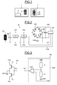
Sur la
La référence 2 désigne un objet, par exemple un téléphone mobile cellulaire émulé en mode carte, et plus généralement un transpondeur électromagnétique (Tag) telle qu'une étiquette ou un badge.The
Cet objet 2 comporte ici un circuit intégré 20 connecté ici à une antenne 200 externe au circuit intégré et magnétiquement couplée à l'antenne 10 du lecteur 1.This
Sur la
Quand l'objet entre dans le champ magnétique du lecteur, une tension haute-fréquence est générée aux bornes du circuit résonant 200-201. Cette tension redressée par le pont redresseur 204 fournit une tension d'alimentation VDD à un circuit électronique 206 de l'objet pouvant par exemple contenir au moins une mémoire et un processeur.When the object enters the magnetic field of the reader, a high-frequency voltage is generated across the resonant circuit 200-201. This voltage rectified by the
Par ailleurs, un condensateur 205 servant de réservoir d'énergie (« buffer capacitor ») est également connecté entre la tension d'alimentation VDD et la masse GND en parallèle sur le circuit électronique 206.Furthermore, a
Généralement, le circuit intégré comporte également un circuit de limitation de tension 203 dont les deux bornes PN3 et PN4 sont reliées aux deux bornes du circuit résonant 200-201. Ce circuit de limitation de tension (également connu par l'homme du métier sous la dénomination anglo-saxonne de « clipping circuit ») est commandable par un signal de commande SCT émanant, dans ce mode de réalisation, du circuit électronique 206.Generally, the integrated circuit also comprises a
Pour permettre la transmission de données depuis l'objet vers le lecteur 1, le circuit électronique 206 commande, par l'intermédiaire d'un signal de commande SCM, l'étage 202 de rétro-modulation du circuit résonant 200-201. Cet étage 202 comporte, comme on le verra plus en détail ci-après, un ensemble de commutateurs électroniques commandés par le signal SCM et un circuit résistif et/ou capacitif, sélectivement commandable par l'intermédiaire des commutateurs, de façon à modifier la charge connectée aux bornes de l'antenne 200 et permettre ainsi d'une part la détection côté lecteur, et d'autre part l'ajustement de l'impédance de cette charge en fonction de la distance entre le lecteur et l'objet.To enable the transmission of data from the object to the
On se réfère maintenant plus particulièrement à la
Comme indiqué ci-avant, lorsque le lecteur génère un champ électromagnétique, par exemple à 13,56MHz, ce champ va induire une tension aux bornes de l'inductance 200 de l'antenne de l'objet. La valeur de cette tension induite dépend du coefficient de couplage entre les antennes du lecteur et de l'objet, de l'intensité du courant utilisé par le lecteur pour générer le champ électromagnétique et de la valeur de l'inductance L.As indicated above, when the reader generates an electromagnetic field, for example at 13.56 MHz, this field will induce a voltage across the
Lorsque l'objet est placé très près du lecteur, la tension induite peut devenir si importante qu'elle peut détruire notamment le circuit électronique 206 si aucune précaution n'est prise.When the object is placed very close to the reader, the induced voltage can become so important that it can destroy in particular the
C'est pourquoi on équipe généralement le circuit intégré du circuit de limitation de tension 203 (« clipping circuit »). Fonctionnellement, dès que la tension induite aux bornes de l'antenne de l'objet atteint une valeur prédéfinie, le circuit de limitation de tension va commuter dans un mode où il va modifier l'impédance de l'antenne de façon à limiter la tension induite. En pratique, l'impédance du circuit de limitation de tension va chuter.This is why we generally equip the integrated circuit of the voltage limiting circuit 203 ("clipping circuit"). Functionally, as soon as the voltage induced across the antenna of the object reaches a predefined value, the voltage limiting circuit will switch in a mode where it will modify the impedance of the antenna so as to limit the voltage induced. In practice, the impedance of the voltage limiting circuit will drop.
Sur la
Ce module de commande 2060 comporte ici un pont diviseur formé de deux résistances R connectées en série entre la tension VDD et la masse GND et dont le point milieu est connecté à l'entrée positive d'un comparateur CMP, l'entrée négative de ce comparateur CMP recevant une tension de référence prédéfinie VRF, par exemple 1,2Volts.This
Si, la tension VDD a valeur inférieure à deux fois la valeur de la tension de référence VRF, le signal SCT aura toujours le niveau logique « 0 », les transistors NMOS T1 et T2 étant alors bloqués.If, the voltage VDD is less than twice the value of the reference voltage VRF, the signal SCT will always have the logic level "0", the NMOS transistors T1 and T2 then being blocked.
Par contre, si la tension VDD excède deux fois la valeur de la tension de référence, les transistors T1 et T2 seront passants ce qui aura pour effet de faire chuter l'impédance vue de l'antenne et par conséquent de réduire la tension induite.On the other hand, if the voltage VDD exceeds twice the value of the reference voltage, the transistors T1 and T2 will pass, which will have the effect of dropping the impedance seen from the antenna and consequently reduce the induced voltage.
Bien que l'on ait décrit ici un dispositif du type « bloqué-passant », à des fins de simplification, la boucle de commande peut être en réalité plus du type « analogique » en ce sens que si la tension VDD a une valeur légèrement supérieure à deux fois la valeur VRF, l'impédance présentée par les transistors T1 et T2 en parallèle sur l'inductance 200 aura une valeur relativement élevée alors que si la tension VDD est significativement plus élevée que deux fois VRF, l'impédance des transistors T1 et T2 sera bien plus faible.Although a "blocked-on" type device has been described here, for purposes of simplification, the control loop may actually be more of the "analog" type in that if the VDD voltage has a value slightly greater than twice the VRF value, the impedance presented by the transistors T1 and T2 in parallel on the
En conclusion, la tension VDD aux bornes du condensateur 205 formant réservoir d'énergie, aura une valeur inférieure ou égale à deux fois la valeur de la tension VRF.In conclusion, the voltage VDD across the
Et, lorsque l'objet est très proche du lecteur, la tension VDD sera limitée à 2VRF. Lorsque la distance entre le lecteur et l'objet augmente, cette tension VDD va rester à la valeur 2VRF jusqu'à ce que sa valeur soit suffisamment basse pour que les transistors du circuit de limitation de tension soient constamment bloqués. Et à partir de là, lorsque la distance augmente encore, la tension VDD va commencer à chuter.And, when the object is very close to the reader, the VDD voltage will be limited to 2VRF. When the distance between the reader and the object increases, this voltage VDD will remain at the value 2VRF until its value is sufficiently low so that the transistors of the voltage limiting circuit are constantly blocked. And from there, when the distance increases further, the VDD voltage will start to drop.
La valeur de la tension VDD peut donc servir ici d'indicateur de la distance entre le lecteur et l'objet.The value of the voltage VDD can thus serve here as an indicator of the distance between the reader and the object.
Le dispositif de gestion du fonctionnement de l'objet comprend des moyens de contrôle, incorporés au moins en partie au sein du circuit électronique 206, configurés pour effectuer une phase de contrôle comportant une estimation de la distance entre l'objet et le lecteur et un ajustement de l'impédance de la charge connectée aux bornes de l'antenne, en fonction de la distance estimée.The device for managing the operation of the object comprises control means, incorporated at least in part within the
Sur la
S'il existe plusieurs phases de transmission successives, une phase de contrôle S30 sera par exemple effectuée avant chaque phase de transmission S31 de façon à prendre en compte un déplacement éventuel de l'objet par rapport au lecteur entre chaque phase de transmission de données.If there are several successive transmission phases, a control phase S30 will for example be performed before each transmission phase S31 so as to take into account any movement of the object relative to the reader between each data transmission phase.
Comme illustré schématiquement sur la
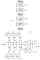
On se réfère maintenant plus particulièrement à la
Dans cet exemple, l'étage de rétro-modulation est purement résistif. Cela étant, dans d'autres cas il pourrait être à la fois résistif et capacitif ou bien purement capacitif.In this example, the retro-modulation stage is purely resistive. However, in other cases it could be both resistive and capacitive or purely capacitive.
Dans cet exemple de réalisation, l'étage de rétro-modulation 202 comporte un réseau résistif R1, R2, R3 connecté et sélectivement commandable par une information de commande SCM dont on verra qu'elle est représentative de la distance estimée. Ce réseau résistif sélectivement commandable fait ainsi partie d'un module d'ajustement configuré pour effectuer un ajustement de l'impédance de la charge connectée aux bornes de l'antenne 200 de l'objet, en fonction de la distance estimée entre l'objet et le lecteur.In this exemplary embodiment, the retro-
Plus précisément, le réseau résistif comporte une première paire de résistances R1 connectées en série entre les bornes PN1 et PN2 par l'intermédiaire d'une paire de commutateurs SW1, par exemple des transistors. Le point milieu de cette structure est connecté à la masse.More specifically, the resistive network comprises a first pair of resistors R1 connected in series between the terminals PN1 and PN2 via a pair of switches SW1, for example transistors. The midpoint of this structure is connected to the ground.
Le réseau résistif comporte également une deuxième paire de résistances R2 également connectées en série entre les bornes PN1 et PN2 par l'intermédiaire d'une paire de deuxième commutateur SW2. Là encore, le point milieu de cette structure est connecté à la masse.The resistive network also comprises a second pair of resistors R2 also connected in series between the terminals PN1 and PN2 via a pair of second switch SW2. Again, the midpoint of this structure is connected to the mass.
Enfin, le module d'ajustement comporte une troisième paire de résistance R3 connectée en série entre les bornes PN1 et PN2 par l'intermédiaire d'une troisième paire de commutateurs SW3. Là encore, le point milieu de cette structure est connecté à la masse.Finally, the adjustment module comprises a third pair of resistor R3 connected in series between the terminals PN1 and PN2 via a third pair of switches SW3. Again, the midpoint of this structure is connected to the mass.
Le module d'ajustement comporte par ailleurs ici un ensemble de trois portes logiques PL1, PL2, PL3, ici des portes logiques ET dont les sorties respectives fournissent trois signaux de commande SC1, SC2, SC3 commandant respectivement les commutateurs SW1, SW2 et SW3.The adjustment module further comprises here a set of three logic gates PL1, PL2, PL3, here logic gates AND whose respective outputs provide three control signals SC1, SC2, SC3 respectively controlling the switches SW1, SW2 and SW3.
Les trois portes logiques PL1-PL3 sont commandées par le signal de commande SCM qui comporte un signal logique élémentaire LM délivré par le circuit électronique et destiné à rétro-moduler l'impédance de la charge en fonction des données à transmettre. Ce signal élémentaire LM est délivré sur chacune des premières entrées des portes logiques PL1-PL3.The three logic gates PL1-PL3 are controlled by the control signal SCM which comprises a logic elementary signal LM delivered by the electronic circuit and intended to retro-modulate the impedance of the load as a function of the data to be transmitted. This elementary signal LM is delivered on each of the first inputs of the logic gates PL1-PL3.
Le signal de commande SCM comporte par ailleurs trois autres signaux élémentaires b0, b1 et b2 délivrés respectivement sur les deuxièmes entrées des trois portes logiques PL1-PL3.The control signal SCM also comprises three other elementary signals b0, b1 and b2 respectively delivered on the second inputs of the three logic gates PL1-PL3.
Chacun des signaux élémentaires LM, b0, b1 et b2 est susceptible de prendre un niveau logique « 0 » ou un niveau logique « 1 ».Each of the elementary signals LM, b0, b1 and b2 is capable of taking a logical level "0" or a logic level "1".
En fonction de la valeur logique des signaux élémentaires b0, b1 et b2, l'une des paires de résistance sera sélectionnée.Depending on the logic value of the elementary signals b0, b1 and b2, one of the resistance pairs will be selected.
Dans cet exemple de réalisation, la valeur des résistances R1 est plus faible que celle des résistances R2 elle-même plus faible que celle des résistances R3. A titre indicatif, on peut prendre par exemple une valeur de 80 Ohms pour les résistances R1, une valeur de 110 Ohms pour les résistances R2 et une valeur de 140 Ohms pour les résistances R3.In this embodiment, the value of the resistors R1 is lower than that of the resistors R2 itself lower than that of the resistors R3. As an indication, one can take for example a value of 80 ohms for the resistors R1, a value of 110 ohms for the resistors R2 and a value of 140 ohms for the resistors R3.
Et, comme on peut le voir maintenant plus en détail, pour une courte distance entre le lecteur et l'objet, c'est la paire de résistances R1 qui va être sélectionnée pour effectuer la rétro-modulation tandis que pour une distance plus grande ce sera la paire de résistances R2 qui va être sélectionnée pour effectuer la rétro-modulation et pour une distance encore plus grande c'est cette fois-ci la paire de résistances R3 qui va être sélectionnée pour effectuer la rétro-modulation.And, as we can see now in more detail, for a short distance between the reader and the object, it is the pair of resistors R1 that will be selected to perform the retro-modulation while for a greater distance this will be the pair of resistors R2 that will be selected to perform the retro-modulation and for an even greater distance this time it is the pair of resistors R3 will be selected to perform the retro-modulation.
Ainsi, pour une distance ou une plage de distance donnée, deux des commutateurs, par exemple les commutateurs SW2 et SW3 seront constamment ouverts tandis que les autres commutateurs SW1 seront ouverts et fermés en fonction de la valeur logique du signal élémentaire LM.Thus, for a given distance or range of distance, two of the switches, for example the switches SW2 and SW3 will be constantly open while the other switches SW1 will be opened and closed according to the logic value of the elementary signal LM.
On se réfère maintenant plus particulièrement à la
Dans ce mode de réalisation, le module d'estimation 2061 est configuré pour effectuer une estimation de l'énergie reçue par l'objet et résultant du champ magnétique irradié par le lecteur et pour comparer cette énergie avec au moins un seuil, en l'espèce deux seuils.In this embodiment, the
Et, à cet égard, le module d'estimation 2061 va utiliser la tension VDD présente aux bornes du condensateur 205 formant un réservoir d'énergie.And, in this regard, the
Deux seuils de tension VR1 et VR2, par exemple égaux à 2,5Volts et 3,5Volts, sont utilisés ici.Two voltage thresholds VR1 and VR2, for example equal to 2.5Volts and 3.5Volts, are used here.
Un étage de comparaison 20610 compare alors la tension VDD à ces deux seuils VR1 et VR2 pour délivrer les signaux élémentaires de commande b0, b1 et b2.A
Plus particulièrement, si la tension VDD est inférieure ou égale à VR1, alors le signal élémentaire b0 et le signal élémentaire b1 prennent la valeur logique « 0 » tandis que le signal élémentaire b2 prend la valeur logique « 1 ».More particularly, if the voltage VDD is less than or equal to VR1, then the elementary signal b0 and the elementary signal b1 take the logical value "0" while the elementary signal b2 takes the logical value "1".
Si la tension VDD est supérieure à VR1 et inférieure ou égale à VR2, alors c'est cette fois-ci le signal logique b1 qui prend la valeur 1 tandis que les signaux logiques b0 et b2 ont la valeur logique 0.If the voltage VDD is greater than VR1 and less than or equal to VR2, then this time it is the logic signal b1 which takes the
Et, si la tension VDD est supérieure à VR2, alors c'est cette fois-ci le signal de commande élémentaire B0 qui prend la valeur logique « 1 « tandis que les signaux de commande élémentaires b1 et b2 prennent la valeur logique « 0 ».And, if the voltage VDD is greater than VR2, then this time it is the elementary control signal B0 which takes the logic value "1" while the elementary control signals b1 and b2 take the logical value "0" .
On se réfère maintenant plus particulièrement aux
Dans cette variante, la distance va être estimée à partir du niveau d'activité du circuit de limitation de tension, et plus particulièrement le facteur d'utilisation (« duty cycle »).In this variant, the distance will be estimated from the activity level of the voltage limiting circuit, and more particularly the duty cycle.
Et, là encore, on va comparer ce niveau d'activité, plus précisément le facteur d'utilisation, à au moins un seuil pour déterminer les valeurs des signaux élémentaires b0, b1 et b2 du signal de commande SCM.And, again, we will compare this level of activity, more precisely the duty factor, to at least one threshold for determining the values of the elementary signals b0, b1 and b2 of the control signal SCM.
Plus précisément, dans ce cas, comme illustré sur la
Cette fois-ci, comme on le voit sur la
On définit alors le facteur d'utilisation du circuit de limitation 203, représentatif du niveau d'activité de ce circuit de limitation de tension comme étant le rapport entre la durée pendant laquelle les transistors T1 et T2 sont passants et la durée pendant laquelle les transistors T1 et T2 sont bloqués.The utilization factor of the limiting
Sur la
Dans le cas 1 (partie gauche de la
On voit dans chacun de ces cas que lorsque la tension VDD1 dépasse deux fois la tension VRF, le signal de commande SCT prend l'état logique « 1 » pour rendre passants les transistors T1 et T2 et prend l'état logique « 0 » dans le cas contraire.It can be seen in each of these cases that when the voltage VDD1 exceeds twice the voltage VRF, the control signal SCT takes the logic state "1" to pass transistors T1 and T2 and takes the logic state "0" in the opposite case.
Et, plus la distance entre l'objet et le lecteur est proche, plus le facteur d'utilisation F sera élevé.And, the closer the distance between the object and the reader, the higher the duty factor F will be.
On peut ainsi définir deux seuils F1 et F2 pour les valeurs de ces facteurs d'utilisation et la comparaison du facteur d'utilisation à ces deux seuils VF1, VF2 permettra de déterminer les valeurs logiques des signaux élémentaires b0, b1 et b2.It is thus possible to define two thresholds F1 and F2 for the values of these utilization factors and the comparison of the utilization factor at these two thresholds VF1, VF2 will make it possible to determine the logic values of the elementary signals b0, b1 and b2.
Matériellement, comme illustré sur la
Claims (16)
Applications Claiming Priority (1)
| Application Number | Priority Date | Filing Date | Title |
|---|---|---|---|
| FR1460249A FR3027754B1 (en) | 2014-10-24 | 2014-10-24 | METHOD FOR MANAGING OPERATION, IN PARTICULAR CHARGE MODULATION, OF AN OBJECT CAPABLE OF COMMUNICATING WITHOUT CONTACT WITH A READER, CORRESPONDING DEVICE AND OBJECT |
Publications (2)
| Publication Number | Publication Date |
|---|---|
| EP3012980A1 true EP3012980A1 (en) | 2016-04-27 |
| EP3012980B1 EP3012980B1 (en) | 2021-03-24 |
Family
ID=53298420
Family Applications (1)
| Application Number | Title | Priority Date | Filing Date |
|---|---|---|---|
| EP15184275.4A Active EP3012980B1 (en) | 2014-10-24 | 2015-09-08 | Method for managing the operation, in particular the load modulation, of an object able to contactless communicate with a reader, and corresponding device and object |
Country Status (4)
| Country | Link |
|---|---|
| US (1) | US9912386B2 (en) |
| EP (1) | EP3012980B1 (en) |
| CN (2) | CN205028302U (en) |
| FR (1) | FR3027754B1 (en) |
Families Citing this family (3)
| Publication number | Priority date | Publication date | Assignee | Title |
|---|---|---|---|---|
| EP3648362B1 (en) * | 2018-11-02 | 2021-03-03 | Stmicroelectronics Sa | Method for limiting the level of voltage from a magnetic field received by a transponder and corresponding transponder |
| CN110401266B (en) * | 2019-07-29 | 2021-02-12 | 歌尔股份有限公司 | Wireless charging receiving end circuit and electronic equipment with wireless charging function |
| EP3829026A1 (en) * | 2019-11-26 | 2021-06-02 | STMicroelectronics (Rousset) SAS | Method of monitoring and controlling a level of power transmitted by an antenna of a contactless communication device |
Citations (2)
| Publication number | Priority date | Publication date | Assignee | Title |
|---|---|---|---|---|
| US20070290846A1 (en) * | 2006-06-07 | 2007-12-20 | Meinhard Schilling | Concept for determining the position or orientation of a transponder in an RFID system |
| WO2013002488A1 (en) * | 2011-06-29 | 2013-01-03 | Lg Innotek Co., Ltd. | Wireless power transmission apparatus and wireless power transmission method thereof |
Family Cites Families (6)
| Publication number | Priority date | Publication date | Assignee | Title |
|---|---|---|---|---|
| US6975245B1 (en) * | 2000-09-18 | 2005-12-13 | Battelle Energy Alliance, Llc | Real-time data acquisition and telemetry based irrigation control system |
| US7327257B2 (en) * | 2004-12-17 | 2008-02-05 | Intel Corporation | RFID tag with modifiable and reversible read range |
| FR2879754A1 (en) * | 2004-12-20 | 2006-06-23 | St Microelectronics Sa | ELECTROMAGNETIC TRANSPONDER WITHOUT AUTONOMOUS POWER SUPPLY |
| KR100659272B1 (en) * | 2005-12-15 | 2006-12-20 | 삼성전자주식회사 | Rfid tag capable of limiting over-voltage and method for controlling over-voltage thereof |
| US7791453B2 (en) * | 2006-11-21 | 2010-09-07 | International Business Machines Corporation | System and method for varying response amplitude of radio transponders |
| JP2009302953A (en) * | 2008-06-13 | 2009-12-24 | Toshiba Corp | Noncontact data communications device |
-
2014
- 2014-10-24 FR FR1460249A patent/FR3027754B1/en not_active Expired - Fee Related
-
2015
- 2015-09-08 EP EP15184275.4A patent/EP3012980B1/en active Active
- 2015-09-14 US US14/853,667 patent/US9912386B2/en active Active
- 2015-09-22 CN CN201520738047.8U patent/CN205028302U/en active Active
- 2015-09-22 CN CN201510608966.8A patent/CN105550611B/en active Active
Patent Citations (2)
| Publication number | Priority date | Publication date | Assignee | Title |
|---|---|---|---|---|
| US20070290846A1 (en) * | 2006-06-07 | 2007-12-20 | Meinhard Schilling | Concept for determining the position or orientation of a transponder in an RFID system |
| WO2013002488A1 (en) * | 2011-06-29 | 2013-01-03 | Lg Innotek Co., Ltd. | Wireless power transmission apparatus and wireless power transmission method thereof |
Also Published As
| Publication number | Publication date |
|---|---|
| US9912386B2 (en) | 2018-03-06 |
| US20160119033A1 (en) | 2016-04-28 |
| FR3027754A1 (en) | 2016-04-29 |
| CN105550611A (en) | 2016-05-04 |
| CN205028302U (en) | 2016-02-10 |
| FR3027754B1 (en) | 2017-12-22 |
| EP3012980B1 (en) | 2021-03-24 |
| CN105550611B (en) | 2020-01-10 |
Similar Documents
| Publication | Publication Date | Title |
|---|---|---|
| EP2443594B1 (en) | Resistive assessment of the coupling coefficient of an electromagnetic transponder | |
| EP3001575B1 (en) | Method for managing the operation of an object capable of contactless communication with a reader, corresponding device and object | |
| EP2267642B1 (en) | Inductive assessment of the coupling coefficient of an electromagnetic transponder | |
| FR2792134A1 (en) | DISTANCE DETECTION BETWEEN AN ELECTROMAGNETIC TRANSPONDER AND A TERMINAL | |
| EP1045336A1 (en) | Close-coupled method of operation of an electromagnetic transpondersystem | |
| FR2792130A1 (en) | ELECTROMAGNETIC TRANSPONDER WITH VERY CLOSE COUPLING OPERATION | |
| EP1043677A1 (en) | Reader for electromagnetic transponders which functions with very short distance coupling | |
| FR2947073A1 (en) | ENERGY MANAGEMENT IN AN ELECTROMAGNETIC TRANSPONDER | |
| EP2114019B1 (en) | Recharge of an active transponder | |
| EP3048743B1 (en) | Method for managing the wireless communication and wireless charging within a system and corresponding system | |
| EP3012980B1 (en) | Method for managing the operation, in particular the load modulation, of an object able to contactless communicate with a reader, and corresponding device and object | |
| EP3413473B1 (en) | Method for controlling the level of power emitted by a contactless communication device, for example, a reader, and corresponding contactless communication device | |
| FR2960993A1 (en) | EVALUATION OF THE COUPLING FACTOR OF AN ELECTROMAGNETIC TRANSPONDER WITH CAPACITIVE DISAGGREGATION | |
| EP2715607B1 (en) | Securing a communication between an electromagnetic transponder and a terminal | |
| EP1369813A1 (en) | Reader for electromagnetic transponder | |
| WO2012164179A1 (en) | Transponder positioning assistance | |
| EP1043679A1 (en) | Reader having means for determining the distance between the reader and a transponder | |
| EP1068652B1 (en) | Device for controlling the impedance returned on an electronic label antenna | |
| EP3648362B1 (en) | Method for limiting the level of voltage from a magnetic field received by a transponder and corresponding transponder | |
| FR2793360A1 (en) | RADIUS POWER CONTROL OF AN INTEGRATED PROXIMITY CIRCUIT CARD READER | |
| FR2808634A1 (en) | IMPROVED DEMODULATION CAPACITY OF AN ELECTROMAGNETIC TRANSPONDER | |
| EP2889809A1 (en) | Device for converting an electromagnetic field | |
| EP2715618A1 (en) | Making a communication secure through an electromagnetic transponder | |
| WO2001082411A1 (en) | Antenna for contact-free transmission/reception reading system | |
| FR3103597A1 (en) | Method of controlling the relative positioning of two objects and corresponding system |
Legal Events
| Date | Code | Title | Description |
|---|---|---|---|
| PUAI | Public reference made under article 153(3) epc to a published international application that has entered the european phase |
Free format text: ORIGINAL CODE: 0009012 |
|
| 17P | Request for examination filed |
Effective date: 20150908 |
|
| AK | Designated contracting states |
Kind code of ref document: A1 Designated state(s): AL AT BE BG CH CY CZ DE DK EE ES FI FR GB GR HR HU IE IS IT LI LT LU LV MC MK MT NL NO PL PT RO RS SE SI SK SM TR |
|
| AX | Request for extension of the european patent |
Extension state: BA ME |
|
| STAA | Information on the status of an ep patent application or granted ep patent |
Free format text: STATUS: EXAMINATION IS IN PROGRESS |
|
| 17Q | First examination report despatched |
Effective date: 20180810 |
|
| GRAP | Despatch of communication of intention to grant a patent |
Free format text: ORIGINAL CODE: EPIDOSNIGR1 |
|
| STAA | Information on the status of an ep patent application or granted ep patent |
Free format text: STATUS: GRANT OF PATENT IS INTENDED |
|
| INTG | Intention to grant announced |
Effective date: 20201106 |
|
| GRAS | Grant fee paid |
Free format text: ORIGINAL CODE: EPIDOSNIGR3 |
|
| GRAA | (expected) grant |
Free format text: ORIGINAL CODE: 0009210 |
|
| STAA | Information on the status of an ep patent application or granted ep patent |
Free format text: STATUS: THE PATENT HAS BEEN GRANTED |
|
| AK | Designated contracting states |
Kind code of ref document: B1 Designated state(s): AL AT BE BG CH CY CZ DE DK EE ES FI FR GB GR HR HU IE IS IT LI LT LU LV MC MK MT NL NO PL PT RO RS SE SI SK SM TR |
|
| REG | Reference to a national code |
Ref country code: GB Ref legal event code: FG4D Free format text: NOT ENGLISH |
|
| REG | Reference to a national code |
Ref country code: CH Ref legal event code: EP |
|
| REG | Reference to a national code |
Ref country code: IE Ref legal event code: FG4D Free format text: LANGUAGE OF EP DOCUMENT: FRENCH |
|
| REG | Reference to a national code |
Ref country code: AT Ref legal event code: REF Ref document number: 1375559 Country of ref document: AT Kind code of ref document: T Effective date: 20210415 Ref country code: DE Ref legal event code: R096 Ref document number: 602015067158 Country of ref document: DE |
|
| REG | Reference to a national code |
Ref country code: LT Ref legal event code: MG9D |
|
| PG25 | Lapsed in a contracting state [announced via postgrant information from national office to epo] |
Ref country code: FI Free format text: LAPSE BECAUSE OF FAILURE TO SUBMIT A TRANSLATION OF THE DESCRIPTION OR TO PAY THE FEE WITHIN THE PRESCRIBED TIME-LIMIT Effective date: 20210324 Ref country code: GR Free format text: LAPSE BECAUSE OF FAILURE TO SUBMIT A TRANSLATION OF THE DESCRIPTION OR TO PAY THE FEE WITHIN THE PRESCRIBED TIME-LIMIT Effective date: 20210625 Ref country code: HR Free format text: LAPSE BECAUSE OF FAILURE TO SUBMIT A TRANSLATION OF THE DESCRIPTION OR TO PAY THE FEE WITHIN THE PRESCRIBED TIME-LIMIT Effective date: 20210324 Ref country code: BG Free format text: LAPSE BECAUSE OF FAILURE TO SUBMIT A TRANSLATION OF THE DESCRIPTION OR TO PAY THE FEE WITHIN THE PRESCRIBED TIME-LIMIT Effective date: 20210624 Ref country code: NO Free format text: LAPSE BECAUSE OF FAILURE TO SUBMIT A TRANSLATION OF THE DESCRIPTION OR TO PAY THE FEE WITHIN THE PRESCRIBED TIME-LIMIT Effective date: 20210624 |
|
| PG25 | Lapsed in a contracting state [announced via postgrant information from national office to epo] |
Ref country code: SE Free format text: LAPSE BECAUSE OF FAILURE TO SUBMIT A TRANSLATION OF THE DESCRIPTION OR TO PAY THE FEE WITHIN THE PRESCRIBED TIME-LIMIT Effective date: 20210324 Ref country code: RS Free format text: LAPSE BECAUSE OF FAILURE TO SUBMIT A TRANSLATION OF THE DESCRIPTION OR TO PAY THE FEE WITHIN THE PRESCRIBED TIME-LIMIT Effective date: 20210324 Ref country code: LV Free format text: LAPSE BECAUSE OF FAILURE TO SUBMIT A TRANSLATION OF THE DESCRIPTION OR TO PAY THE FEE WITHIN THE PRESCRIBED TIME-LIMIT Effective date: 20210324 |
|
| REG | Reference to a national code |
Ref country code: NL Ref legal event code: MP Effective date: 20210324 |
|
| REG | Reference to a national code |
Ref country code: AT Ref legal event code: MK05 Ref document number: 1375559 Country of ref document: AT Kind code of ref document: T Effective date: 20210324 |
|
| PG25 | Lapsed in a contracting state [announced via postgrant information from national office to epo] |
Ref country code: NL Free format text: LAPSE BECAUSE OF FAILURE TO SUBMIT A TRANSLATION OF THE DESCRIPTION OR TO PAY THE FEE WITHIN THE PRESCRIBED TIME-LIMIT Effective date: 20210324 |
|
| PG25 | Lapsed in a contracting state [announced via postgrant information from national office to epo] |
Ref country code: SM Free format text: LAPSE BECAUSE OF FAILURE TO SUBMIT A TRANSLATION OF THE DESCRIPTION OR TO PAY THE FEE WITHIN THE PRESCRIBED TIME-LIMIT Effective date: 20210324 Ref country code: LT Free format text: LAPSE BECAUSE OF FAILURE TO SUBMIT A TRANSLATION OF THE DESCRIPTION OR TO PAY THE FEE WITHIN THE PRESCRIBED TIME-LIMIT Effective date: 20210324 Ref country code: EE Free format text: LAPSE BECAUSE OF FAILURE TO SUBMIT A TRANSLATION OF THE DESCRIPTION OR TO PAY THE FEE WITHIN THE PRESCRIBED TIME-LIMIT Effective date: 20210324 Ref country code: CZ Free format text: LAPSE BECAUSE OF FAILURE TO SUBMIT A TRANSLATION OF THE DESCRIPTION OR TO PAY THE FEE WITHIN THE PRESCRIBED TIME-LIMIT Effective date: 20210324 Ref country code: AT Free format text: LAPSE BECAUSE OF FAILURE TO SUBMIT A TRANSLATION OF THE DESCRIPTION OR TO PAY THE FEE WITHIN THE PRESCRIBED TIME-LIMIT Effective date: 20210324 |
|
| PG25 | Lapsed in a contracting state [announced via postgrant information from national office to epo] |
Ref country code: PT Free format text: LAPSE BECAUSE OF FAILURE TO SUBMIT A TRANSLATION OF THE DESCRIPTION OR TO PAY THE FEE WITHIN THE PRESCRIBED TIME-LIMIT Effective date: 20210726 Ref country code: PL Free format text: LAPSE BECAUSE OF FAILURE TO SUBMIT A TRANSLATION OF THE DESCRIPTION OR TO PAY THE FEE WITHIN THE PRESCRIBED TIME-LIMIT Effective date: 20210324 Ref country code: ES Free format text: LAPSE BECAUSE OF FAILURE TO SUBMIT A TRANSLATION OF THE DESCRIPTION OR TO PAY THE FEE WITHIN THE PRESCRIBED TIME-LIMIT Effective date: 20210324 Ref country code: SK Free format text: LAPSE BECAUSE OF FAILURE TO SUBMIT A TRANSLATION OF THE DESCRIPTION OR TO PAY THE FEE WITHIN THE PRESCRIBED TIME-LIMIT Effective date: 20210324 Ref country code: RO Free format text: LAPSE BECAUSE OF FAILURE TO SUBMIT A TRANSLATION OF THE DESCRIPTION OR TO PAY THE FEE WITHIN THE PRESCRIBED TIME-LIMIT Effective date: 20210324 Ref country code: IS Free format text: LAPSE BECAUSE OF FAILURE TO SUBMIT A TRANSLATION OF THE DESCRIPTION OR TO PAY THE FEE WITHIN THE PRESCRIBED TIME-LIMIT Effective date: 20210724 |
|
| REG | Reference to a national code |
Ref country code: DE Ref legal event code: R097 Ref document number: 602015067158 Country of ref document: DE |
|
| PG25 | Lapsed in a contracting state [announced via postgrant information from national office to epo] |
Ref country code: DK Free format text: LAPSE BECAUSE OF FAILURE TO SUBMIT A TRANSLATION OF THE DESCRIPTION OR TO PAY THE FEE WITHIN THE PRESCRIBED TIME-LIMIT Effective date: 20210324 Ref country code: AL Free format text: LAPSE BECAUSE OF FAILURE TO SUBMIT A TRANSLATION OF THE DESCRIPTION OR TO PAY THE FEE WITHIN THE PRESCRIBED TIME-LIMIT Effective date: 20210324 |
|
| PLBE | No opposition filed within time limit |
Free format text: ORIGINAL CODE: 0009261 |
|
| STAA | Information on the status of an ep patent application or granted ep patent |
Free format text: STATUS: NO OPPOSITION FILED WITHIN TIME LIMIT |
|
| PG25 | Lapsed in a contracting state [announced via postgrant information from national office to epo] |
Ref country code: SI Free format text: LAPSE BECAUSE OF FAILURE TO SUBMIT A TRANSLATION OF THE DESCRIPTION OR TO PAY THE FEE WITHIN THE PRESCRIBED TIME-LIMIT Effective date: 20210324 |
|
| 26N | No opposition filed |
Effective date: 20220104 |
|
| REG | Reference to a national code |
Ref country code: CH Ref legal event code: PL |
|
| REG | Reference to a national code |
Ref country code: BE Ref legal event code: MM Effective date: 20210930 |
|
| GBPC | Gb: european patent ceased through non-payment of renewal fee |
Effective date: 20210908 |
|
| PG25 | Lapsed in a contracting state [announced via postgrant information from national office to epo] |
Ref country code: IS Free format text: LAPSE BECAUSE OF FAILURE TO SUBMIT A TRANSLATION OF THE DESCRIPTION OR TO PAY THE FEE WITHIN THE PRESCRIBED TIME-LIMIT Effective date: 20210724 Ref country code: MC Free format text: LAPSE BECAUSE OF FAILURE TO SUBMIT A TRANSLATION OF THE DESCRIPTION OR TO PAY THE FEE WITHIN THE PRESCRIBED TIME-LIMIT Effective date: 20210324 |
|
| PG25 | Lapsed in a contracting state [announced via postgrant information from national office to epo] |
Ref country code: LU Free format text: LAPSE BECAUSE OF NON-PAYMENT OF DUE FEES Effective date: 20210908 Ref country code: IE Free format text: LAPSE BECAUSE OF NON-PAYMENT OF DUE FEES Effective date: 20210908 Ref country code: GB Free format text: LAPSE BECAUSE OF NON-PAYMENT OF DUE FEES Effective date: 20210908 Ref country code: BE Free format text: LAPSE BECAUSE OF NON-PAYMENT OF DUE FEES Effective date: 20210930 |
|
| PG25 | Lapsed in a contracting state [announced via postgrant information from national office to epo] |
Ref country code: LI Free format text: LAPSE BECAUSE OF NON-PAYMENT OF DUE FEES Effective date: 20210930 Ref country code: CH Free format text: LAPSE BECAUSE OF NON-PAYMENT OF DUE FEES Effective date: 20210930 |
|
| PG25 | Lapsed in a contracting state [announced via postgrant information from national office to epo] |
Ref country code: IT Free format text: LAPSE BECAUSE OF FAILURE TO SUBMIT A TRANSLATION OF THE DESCRIPTION OR TO PAY THE FEE WITHIN THE PRESCRIBED TIME-LIMIT Effective date: 20210324 |
|
| PG25 | Lapsed in a contracting state [announced via postgrant information from national office to epo] |
Ref country code: HU Free format text: LAPSE BECAUSE OF FAILURE TO SUBMIT A TRANSLATION OF THE DESCRIPTION OR TO PAY THE FEE WITHIN THE PRESCRIBED TIME-LIMIT; INVALID AB INITIO Effective date: 20150908 |
|
| PG25 | Lapsed in a contracting state [announced via postgrant information from national office to epo] |
Ref country code: CY Free format text: LAPSE BECAUSE OF FAILURE TO SUBMIT A TRANSLATION OF THE DESCRIPTION OR TO PAY THE FEE WITHIN THE PRESCRIBED TIME-LIMIT Effective date: 20210324 |
|
| PGFP | Annual fee paid to national office [announced via postgrant information from national office to epo] |
Ref country code: FR Payment date: 20230822 Year of fee payment: 9 Ref country code: DE Payment date: 20230822 Year of fee payment: 9 |