EP3012980A1 - Verfahren zur steuerung des betriebs, insbesondere der belastungsmodulation, eines objekts, das in der lage ist, kontaktlos mit einem lesegerät zu kommunizieren, entsprechende vorrichtung und entsprechendes objekt - Google Patents
Verfahren zur steuerung des betriebs, insbesondere der belastungsmodulation, eines objekts, das in der lage ist, kontaktlos mit einem lesegerät zu kommunizieren, entsprechende vorrichtung und entsprechendes objekt Download PDFInfo
- Publication number
- EP3012980A1 EP3012980A1 EP15184275.4A EP15184275A EP3012980A1 EP 3012980 A1 EP3012980 A1 EP 3012980A1 EP 15184275 A EP15184275 A EP 15184275A EP 3012980 A1 EP3012980 A1 EP 3012980A1
- Authority
- EP
- European Patent Office
- Prior art keywords
- reader
- distance
- antenna
- impedance
- voltage
- Prior art date
- Legal status (The legal status is an assumption and is not a legal conclusion. Google has not performed a legal analysis and makes no representation as to the accuracy of the status listed.)
- Granted
Links
- 238000000034 method Methods 0.000 title claims abstract description 10
- 238000004891 communication Methods 0.000 claims description 15
- 230000000694 effects Effects 0.000 claims description 14
- 230000005540 biological transmission Effects 0.000 claims description 13
- 239000003990 capacitor Substances 0.000 claims description 10
- 238000012545 processing Methods 0.000 claims description 7
- 230000006870 function Effects 0.000 description 8
- 238000005516 engineering process Methods 0.000 description 7
- 230000008878 coupling Effects 0.000 description 5
- 238000010168 coupling process Methods 0.000 description 5
- 238000005859 coupling reaction Methods 0.000 description 5
- 230000001413 cellular effect Effects 0.000 description 4
- 230000009467 reduction Effects 0.000 description 3
- 102100036285 25-hydroxyvitamin D-1 alpha hydroxylase, mitochondrial Human genes 0.000 description 2
- 101000875403 Homo sapiens 25-hydroxyvitamin D-1 alpha hydroxylase, mitochondrial Proteins 0.000 description 2
- 230000007423 decrease Effects 0.000 description 2
- 230000005672 electromagnetic field Effects 0.000 description 2
- 208000019300 CLIPPERS Diseases 0.000 description 1
- 230000008859 change Effects 0.000 description 1
- 208000021930 chronic lymphocytic inflammation with pontine perivascular enhancement responsive to steroids Diseases 0.000 description 1
- 238000001514 detection method Methods 0.000 description 1
- 230000004048 modification Effects 0.000 description 1
- 238000012986 modification Methods 0.000 description 1
- 238000012546 transfer Methods 0.000 description 1
Images


Classifications
-
- H04B5/24—
-
- G—PHYSICS
- G06—COMPUTING; CALCULATING OR COUNTING
- G06K—GRAPHICAL DATA READING; PRESENTATION OF DATA; RECORD CARRIERS; HANDLING RECORD CARRIERS
- G06K7/00—Methods or arrangements for sensing record carriers, e.g. for reading patterns
- G06K7/10—Methods or arrangements for sensing record carriers, e.g. for reading patterns by electromagnetic radiation, e.g. optical sensing; by corpuscular radiation
- G06K7/10009—Methods or arrangements for sensing record carriers, e.g. for reading patterns by electromagnetic radiation, e.g. optical sensing; by corpuscular radiation sensing by radiation using wavelengths larger than 0.1 mm, e.g. radio-waves or microwaves
-
- H04B5/72—
-
- H04B5/77—
Definitions
- Embodiments and embodiments of the invention relate to the wireless communication between a reader and an object, for example a tag-type transponder ("tag" in English), a contactless smart card or a mobile phone emulated in card mode without these examples being limiting, and more particularly the management of the charge modulation performed within such an object, in particular an object NFC ("Near Field Communication").
- tag tag-type transponder
- NFC Near Field Communication
- Near field communication is a wireless connectivity technology that allows communication over a short distance, for example 10 cm, between electronic devices.
- electronic devices such as contactless smart cards or card-emulated smartphones, and readers.
- NFC technology is particularly suitable for connecting any type of user device and allows for quick and easy communications.
- a non-contact object is an object capable of exchanging information via an antenna with another non-contact object, for example a reader, according to a contactless communication protocol.
- An NFC object which is a contactless object, is an object compatible with NFC technology.
- NFC technology is an open standard technology platform in ISO / IEC 18092 and ISO / IEC 21481, but incorporates many existing standards such as the Type A and Type B protocols defined in ISO-14443. can be communication protocols that can be used in NFC technology.
- a cellular mobile phone may be used (if equipped with specific means) to exchange information with another contactless device, for example a contactless reader, using a contactless communication protocol usable in NFC technology.
- the reader When transmitting information between a reader and an emulated object in label or card mode, the reader generates a magnetic field via its antenna which is generally in the standards conventionally used, a sine wave at 13.56MHz .
- the strength of the magnetic field is between 0.5 and 7.5 amps / meter RMS ("Root Mean Square" in English).
- the antenna of the object emulating the label modulates the field generated by the reader.
- This modulation is performed by modifying the load connected to the terminals of the antenna of the object.
- the output impedance of the antenna of the reader changes due to the magnetic coupling between the two antennas. This results in a change in the amplitudes and / or the phases of the voltages and currents present at the antennas of the reader and the object. And, in this way, the information to be transmitted from the object to the reader is transmitted by charge modulation to the antenna current of the reader.
- the load variation performed during the load modulation results in an amplitude and / or phase modulation of the signal (voltage or current) at the antenna of the reader.
- a copy of the antenna current is generated and injected into the reception channel of the reader where it is demodulated and processed so as to extract the transmitted information.
- the best power transfer between the reader and the label is obtained when the label is equipped with a circuit matched with the resonant circuit of the reader, and resonating itself with the frequency of the signal transmitted by the reader, for example 13 , 56 MHz.
- the label when the label is very far from the reader and even if the resonant frequency of the resonant circuit of the label is equal to the frequency of emissions (13.56 MHz for example) it will result in a modification of the resonance frequency of the resonant circuit of the reader, certainly to a lesser extent, due to the reduction of the magnetic coupling between the reader and the label.
- a method of managing the operation of an object capable of communicating without contact with a reader magnetically coupled to said object comprising at least one phase of transmitting information from said object to the reader comprising a modulation the impedance of a load connected to the terminals of the antenna of said object.
- the method further comprises a control phase comprising an estimate of the distance between said object and the reader and an adjustment of the impedance of said load as a function of the estimated distance.
- the adjustment of the impedance of the charge as a function of the estimated distance between the reader and the label makes it possible to overcome any variations in power transmitted by the reader mentioned above and resulting from the magnetic coupling between the respective antennas of the reader and the label.
- the control phase may be performed prior to the transmission phase or possibly created during this transmission phase to take into account a possible movement of the object during the transmission phase.
- the impedance adjustment of the load advantageously comprises a variation of the load impedance in the same direction as that of the variation of the distance.
- the more the distance between the reader and the object decreases the more the impedance will decrease.
- the more the distance will increase the more the impedance will increase.
- the estimate of the distance comprises an estimate of the energy received by said object and resulting from the magnetic field irradiated by the reader and a comparison of the level of this energy, with at least one threshold.
- the estimation of the energy comprises the determination of a voltage across a capacitor. acting as an energy reservoir and connected between the rectifier element and the treatment circuit.
- said object also comprises a controllable voltage limiting circuit (better known by the man of the trade under the name Anglo-Saxon “clipping device” or “clipper”) connected to the terminals of the antenna and intended to absorb any overvoltages.
- a controllable voltage limiting circuit better known by the man of the trade under the name Anglo-Saxon “clipping device” or “clipper” connected to the terminals of the antenna and intended to absorb any overvoltages.
- the estimation of said distance comprises a determination of the activity level of the voltage limiting circuit and a comparison of this level of activity with at least one threshold.
- the communication may for example be a near-field communication type NFC ("Near Field Communication").
- a device for managing the operation of an object capable of communicating without contact with a reader magnetically coupled to said object, comprising first means configured to effect a modulation of the impedance of a load connected to the terminals of the antenna during a phase of transmitting information from said object to the reader.
- the device further comprises control means comprising an estimation module configured to make an estimation of the distance between said object and the reader and an adjustment module configured to perform a calibration adjustment. the impedance of said load as a function of the estimated distance.
- the first means (retro-modulation step) and the adjustment module advantageously comprise common elements.
- the adjustment module is configured to vary the load impedance in the same direction as that of the variation of the distance.
- the adjustment module comprises a resistive and / or capacitive network connected to the terminals of the antenna, selectively controllable by control information representative of said estimated distance.
- the estimation module is configured to make an estimate of the energy received by said object and resulting from the magnetic field irradiated by the reader and a comparison of the level of this energy with at least one threshold.
- the estimation module comprises a capacitor acting as a reservoir of energy and connected between the rectifying element and said processing circuit, means configured to compare said voltage with said at least one threshold.
- said estimation module comprises a controllable voltage limiting circuit connected to the terminals of the antenna, means configured to determine the activity level of the voltage limiting circuit and a configured comparison stage. to compare this level of activity to at least one threshold.
- the device as defined above can advantageously be implemented in an integrated manner.
- an object for example a smart card, a label, a cellular mobile phone that can be emulated in card mode, incorporating a device as defined above.
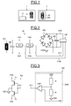
- reference numeral 1 designates a reader, for example but not limited to a cellular mobile phone emulated in reader mode or a conventional contactless smart card or tag (Tag) reader such as a badge, including an antenna 10 and a vector demodulator 11 configured to perform an amplitude and / or phase demodulation of a signal that can be modulated in amplitude and / or in phase and received at the antenna 10, for example the voltage at the terminals of this antenna.
- the reader 1 is intended to irradiate a magnetic field.
- the reference 2 designates an object, for example a cellular mobile phone emulated in card mode, and more generally an electromagnetic transponder (Tag) such as a tag or a badge.
- Tag electromagnetic transponder
- This object 2 here comprises an integrated circuit 20 connected here to an antenna 200 external to the integrated circuit and magnetically coupled to the antenna 10 of the reader 1.
- the integrated circuit here comprises a capacitor 201 forming, with the coil 200, a parallel resonant circuit permitting with a back-modulation stage 202 to modulate the magnetic field generated by an oscillating circuit of the reader.
- This resonant circuit 200-201 is connected to the two alternating inputs of a diode rectifier bridge 204.
- a diode rectifier bridge 204 In a variant, it would be possible to use as a rectifying element a single-wave rectification element.
- a high-frequency voltage is generated across the resonant circuit 200-201.
- This voltage rectified by the rectifier bridge 204 provides a supply voltage VDD to an electronic circuit 206 of the object may for example contain at least one memory and a processor.
- a capacitor 205 serving as a buffer capacitor is also connected between the supply voltage VDD and GND ground in parallel on the electronic circuit 206.
- the integrated circuit also comprises a voltage limiting circuit 203 whose two terminals PN3 and PN4 are connected to the two terminals of the resonant circuit 200-201.
- This voltage limiting circuit (also known by a person skilled in the art as “clipping circuit”) is controllable by a control signal SCT emanating, in this embodiment, from the electronic circuit 206.
- the electronic circuit 206 controls, via a control signal SCM, the back modulation stage 202 of the resonant circuit 200-201.
- This stage 202 comprises, as will be seen in more detail below, a set of electronic switches controlled by the signal SCM and a resistive and / or capacitive circuit, selectively controllable by means of the switches, so as to modify the load connected to the terminals of the antenna 200 and thus allow on the one hand the detection on the reader side, and on the other hand the adjustment of the impedance of this load as a function of the distance between the reader and the object.
- this field will induce a voltage across the inductor 200 of the antenna of the object.
- the value of this induced voltage depends on the coupling coefficient between the antenna of the reader and the object, the intensity of the current used by the reader to generate the electromagnetic field and the value of the inductance L.
- the induced voltage can become so important that it can destroy in particular the electronic circuit 206 if no precautions are taken.
- the voltage limiting circuit 203 (clipping circuit"). Functionally, as soon as the voltage induced across the antenna of the object reaches a predefined value, the voltage limiting circuit will switch in a mode where it will modify the impedance of the antenna so as to limit the voltage induced. In practice, the impedance of the voltage limiting circuit will drop.
- the voltage limiting circuit 203 comprises a first NMOS transistor T1 connected between the terminal PN3 and the ground GND and a second NMOS transistor T2 connected between the terminal PN4 and the ground GND.
- the gates of these two transistors are controlled by the control signal SCT issued by a control module 2060 for example incorporated in the electronic circuit 206.
- This control module 2060 here comprises a divider bridge formed of two resistors R connected in series between the voltage VDD and GND ground and whose midpoint is connected to the positive input of a comparator CMP, the negative input of which CMP comparator receiving a predefined reference voltage VRF, for example 1.2Volts.
- the signal SCT will always have the logic level "0", the NMOS transistors T1 and T2 then being blocked.
- the transistors T1 and T2 will pass, which will have the effect of dropping the impedance seen from the antenna and consequently reduce the induced voltage.
- control loop may actually be more of the "analog" type in that if the VDD voltage has a value slightly greater than twice the VRF value, the impedance presented by the transistors T1 and T2 in parallel on the inductor 200 will have a relatively high value whereas if the voltage VDD is significantly higher than twice VRF, the impedance of the transistors T1 and T2 will be much lower.
- the voltage VDD across the capacitor 205 forming the energy reservoir will have a value less than or equal to twice the value of the voltage VRF.
- VDD voltage when the object is very close to the reader, the VDD voltage will be limited to 2VRF.
- this voltage VDD will remain at the value 2VRF until its value is sufficiently low so that the transistors of the voltage limiting circuit are constantly blocked. And from there, when the distance increases further, the VDD voltage will start to drop.
- the value of the voltage VDD can thus serve here as an indicator of the distance between the reader and the object.
- the device for managing the operation of the object comprises control means, incorporated at least in part within the electronic circuit 206, configured to perform a control phase comprising an estimate of the distance between the object and the reader and a adjusting the impedance of the load connected to the terminals of the antenna, according to the estimated distance.
- control phase S30 is carried out prior to the transmission phase S31.
- control phase could also be carried out during the transmission phase.
- a control phase S30 will for example be performed before each transmission phase S31 so as to take into account any movement of the object relative to the reader between each data transmission phase.
- control phase S30 comprises an estimate S300 of distance between the reader and the object and an adjustment S301 of the impedance of the load connected to the antenna as a function of the estimated distance.
- the retro-modulation stage is purely resistive. However, in other cases it could be both resistive and capacitive or purely capacitive.
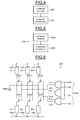
- the retro-modulation stage 202 comprises a resistive network R1, R2, R3 connected and selectively controllable by an SCM control information which will be seen to be representative of the estimated distance.
- This selectively controllable resistive network thus forms part of an adjustment module configured to adjust the impedance of the load connected to the terminals of the antenna 200 of the object, as a function of the estimated distance between the object and the reader.
- the resistive network comprises a first pair of resistors R1 connected in series between the terminals PN1 and PN2 via a pair of switches SW1, for example transistors.
- the midpoint of this structure is connected to the ground.
- the resistive network also comprises a second pair of resistors R2 also connected in series between the terminals PN1 and PN2 via a pair of second switch SW2. Again, the midpoint of this structure is connected to the mass.
- the adjustment module comprises a third pair of resistor R3 connected in series between the terminals PN1 and PN2 via a third pair of switches SW3. Again, the midpoint of this structure is connected to the mass.
- the adjustment module further comprises here a set of three logic gates PL1, PL2, PL3, here logic gates AND whose respective outputs provide three control signals SC1, SC2, SC3 respectively controlling the switches SW1, SW2 and SW3.
- the three logic gates PL1-PL3 are controlled by the control signal SCM which comprises a logic elementary signal LM delivered by the electronic circuit and intended to retro-modulate the impedance of the load as a function of the data to be transmitted.
- This elementary signal LM is delivered on each of the first inputs of the logic gates PL1-PL3.
- the control signal SCM also comprises three other elementary signals b0, b1 and b2 respectively delivered on the second inputs of the three logic gates PL1-PL3.
- Each of the elementary signals LM, b0, b1 and b2 is capable of taking a logical level "0" or a logic level "1".
- one of the resistance pairs will be selected.
- the value of the resistors R1 is lower than that of the resistors R2 itself lower than that of the resistors R3.
- two of the switches for example the switches SW2 and SW3 will be constantly open while the other switches SW1 will be opened and closed according to the logic value of the elementary signal LM.
- an estimation module 2061 configured to estimate the distance between the object and the reader.
- the estimation module 2061 is configured to make an estimation of the energy received by the object and resulting from the magnetic field irradiated by the reader and to compare this energy with at least one threshold, in the species two thresholds.
- the estimation module 2061 will use the voltage VDD present across the capacitor 205 forming a reservoir of energy.
- Two voltage thresholds VR1 and VR2 for example equal to 2.5Volts and 3.5Volts, are used here.
- a comparison stage 20610 then compares the voltage VDD at these two thresholds VR1 and VR2 to deliver the elementary control signals b0, b1 and b2.
- the elementary signal b0 and the elementary signal b1 take the logical value "0" while the elementary signal b2 takes the logical value "1".
- the distance will be estimated from the activity level of the voltage limiting circuit, and more particularly the duty cycle.
- this level of activity more precisely the duty factor, to at least one threshold for determining the values of the elementary signals b0, b1 and b2 of the control signal SCM.
- the integrated circuit 20 comprises in addition to the elements which have been described with reference to the figure 2 an additional rectifier bridge 207 also connected to the terminals of the external antenna 200 and providing a rectified but unfiltered voltage VDD1 to the control module 2060 similar to that described with reference to FIG. figure 3 and which outputs the control signal SCT of the voltage limiting circuit 203.
- control module 2060 is located outside the electronic circuit 206, the latter however providing the value VRF to the comparator CMP.
- the utilization factor of the limiting circuit 203 is then defined as being the ratio between the duration during which the transistors T1 and T2 are on and the duration during which the transistors T1 and T2 are blocked.
- case 1 left part of the figure 9
- the object is supposed to be at a greater distance from the object than in case 2 (right part of the figure 9 ).
- this comparison is performed in a comparison stage 20620 of the estimation module 2062.
Landscapes
- Engineering & Computer Science (AREA)
- Toxicology (AREA)
- Physics & Mathematics (AREA)
- Health & Medical Sciences (AREA)
- Artificial Intelligence (AREA)
- General Health & Medical Sciences (AREA)
- Electromagnetism (AREA)
- Computer Vision & Pattern Recognition (AREA)
- General Physics & Mathematics (AREA)
- Theoretical Computer Science (AREA)
- Near-Field Transmission Systems (AREA)
- Computer Networks & Wireless Communication (AREA)
- Signal Processing (AREA)
- Power Engineering (AREA)
Applications Claiming Priority (1)
| Application Number | Priority Date | Filing Date | Title |
|---|---|---|---|
| FR1460249A FR3027754B1 (fr) | 2014-10-24 | 2014-10-24 | Procede de gestion du fonctionnement, en particulier de la modulation de charge, d'un objet capable de communiquer sans contact avec un lecteur, dispositif et objet correspondants |
Publications (2)
| Publication Number | Publication Date |
|---|---|
| EP3012980A1 true EP3012980A1 (de) | 2016-04-27 |
| EP3012980B1 EP3012980B1 (de) | 2021-03-24 |
Family
ID=53298420
Family Applications (1)
| Application Number | Title | Priority Date | Filing Date |
|---|---|---|---|
| EP15184275.4A Active EP3012980B1 (de) | 2014-10-24 | 2015-09-08 | Verfahren zur steuerung des betriebs, insbesondere der belastungsmodulation, eines objekts, das in der lage ist, kontaktlos mit einem lesegerät zu kommunizieren, entsprechende vorrichtung und entsprechendes objekt |
Country Status (4)
| Country | Link |
|---|---|
| US (1) | US9912386B2 (de) |
| EP (1) | EP3012980B1 (de) |
| CN (2) | CN105550611B (de) |
| FR (1) | FR3027754B1 (de) |
Families Citing this family (3)
| Publication number | Priority date | Publication date | Assignee | Title |
|---|---|---|---|---|
| EP3648362B1 (de) * | 2018-11-02 | 2021-03-03 | Stmicroelectronics Sa | Verfahren zur beschränkung des über einen transponder empfangenen spannungsniveaus aus einem magnetfeld, und entsprechender transponder |
| CN110401266B (zh) * | 2019-07-29 | 2021-02-12 | 歌尔股份有限公司 | 无线充电的接收端电路及具有无线充电功能的电子设备 |
| EP3829026A1 (de) * | 2019-11-26 | 2021-06-02 | STMicroelectronics (Rousset) SAS | Verfahren zur überwachung und steuerung eines durch eine antenne einer kontaktlosen kommunikationsvorrichtung übertragenen leistungsniveaus |
Citations (2)
| Publication number | Priority date | Publication date | Assignee | Title |
|---|---|---|---|---|
| US20070290846A1 (en) * | 2006-06-07 | 2007-12-20 | Meinhard Schilling | Concept for determining the position or orientation of a transponder in an RFID system |
| WO2013002488A1 (en) * | 2011-06-29 | 2013-01-03 | Lg Innotek Co., Ltd. | Wireless power transmission apparatus and wireless power transmission method thereof |
Family Cites Families (6)
| Publication number | Priority date | Publication date | Assignee | Title |
|---|---|---|---|---|
| US6975245B1 (en) * | 2000-09-18 | 2005-12-13 | Battelle Energy Alliance, Llc | Real-time data acquisition and telemetry based irrigation control system |
| US7327257B2 (en) * | 2004-12-17 | 2008-02-05 | Intel Corporation | RFID tag with modifiable and reversible read range |
| FR2879754A1 (fr) * | 2004-12-20 | 2006-06-23 | St Microelectronics Sa | Transpondeur electromagnetique depourvu d'alimentation autonome |
| KR100659272B1 (ko) * | 2005-12-15 | 2006-12-20 | 삼성전자주식회사 | 과전압 제어가 가능한 무선인증용 태그 및 그의 과전압제어 방법 |
| US7791453B2 (en) * | 2006-11-21 | 2010-09-07 | International Business Machines Corporation | System and method for varying response amplitude of radio transponders |
| JP2009302953A (ja) * | 2008-06-13 | 2009-12-24 | Toshiba Corp | 非接触データ通信装置 |
-
2014
- 2014-10-24 FR FR1460249A patent/FR3027754B1/fr not_active Expired - Fee Related
-
2015
- 2015-09-08 EP EP15184275.4A patent/EP3012980B1/de active Active
- 2015-09-14 US US14/853,667 patent/US9912386B2/en active Active
- 2015-09-22 CN CN201510608966.8A patent/CN105550611B/zh active Active
- 2015-09-22 CN CN201520738047.8U patent/CN205028302U/zh active Active
Patent Citations (2)
| Publication number | Priority date | Publication date | Assignee | Title |
|---|---|---|---|---|
| US20070290846A1 (en) * | 2006-06-07 | 2007-12-20 | Meinhard Schilling | Concept for determining the position or orientation of a transponder in an RFID system |
| WO2013002488A1 (en) * | 2011-06-29 | 2013-01-03 | Lg Innotek Co., Ltd. | Wireless power transmission apparatus and wireless power transmission method thereof |
Also Published As
| Publication number | Publication date |
|---|---|
| FR3027754A1 (fr) | 2016-04-29 |
| US9912386B2 (en) | 2018-03-06 |
| CN105550611A (zh) | 2016-05-04 |
| EP3012980B1 (de) | 2021-03-24 |
| CN105550611B (zh) | 2020-01-10 |
| FR3027754B1 (fr) | 2017-12-22 |
| CN205028302U (zh) | 2016-02-10 |
| US20160119033A1 (en) | 2016-04-28 |
Similar Documents
| Publication | Publication Date | Title |
|---|---|---|
| EP3001575B1 (de) | Verfahren zur steuerung des betriebs eines objekts, das in der lage ist, ohne einen kontakt mit einem lesegerät zu kommunizieren, entsprechende vorrichtung und entsprechendes objekt | |
| EP2267642B1 (de) | Induktive Einschätzung des Kopplungsfaktors eines elektromagnetischen Transponders | |
| FR2792134A1 (fr) | Detection de distance entre un transpondeur electromagnetique et une borne | |
| EP1045336A1 (de) | Enggekoppeltes Betriebsverfahren eines elektromagnetischen Transpondersystem | |
| FR2792130A1 (fr) | Transpondeur electromagnetique a fonctionnement en couplage tres proche | |
| WO2010146278A1 (fr) | Gestion de puissance dans un transpondeur electromagnetique | |
| EP1043677A1 (de) | Ein mit sehr naher Koppelung arbeitendes Lesegerät für elektromagnetische Transponder | |
| FR2947073A1 (fr) | Gestion d'energie dans un transpondeur electromagnetique | |
| EP2114019B1 (de) | Wiederaufladung eines aktiven Transponders | |
| EP3048743B1 (de) | Verfahren zur steuerung der kontaktlosen kommunikation und der kontaktlosen ladung innerhalb eines systems, und entsprechendes system | |
| EP3012980B1 (de) | Verfahren zur steuerung des betriebs, insbesondere der belastungsmodulation, eines objekts, das in der lage ist, kontaktlos mit einem lesegerät zu kommunizieren, entsprechende vorrichtung und entsprechendes objekt | |
| FR2960993A1 (fr) | Evaluation du facteur de couplage d'un transpondeur electromagnetique par desaccord capacitif | |
| EP3413473B1 (de) | Kontrollverfahren des niveaus der von einer kontaktlosen kommunikationsvorrichtung gelieferten leistung, beispielsweise einem lesegerät, und entsprechende kontaktlose kommunikationsvorrichtung | |
| EP1369813B1 (de) | Lesegerät für einen elektromagnetischen Transponder | |
| EP1794896B1 (de) | Kontaktlose datenschutzvorrichtung | |
| EP2715607B1 (de) | Sicherung einer kommunikation zwischen einem elektromagnetischen transponder und einem endgerät | |
| EP2715615A1 (de) | Transponderpositionierhilfe | |
| EP1043679A1 (de) | Leser mit Einrichtung zur Bestimmung des Abstandes zwischen dem Leser und einem Transponder | |
| EP3648362B1 (de) | Verfahren zur beschränkung des über einen transponder empfangenen spannungsniveaus aus einem magnetfeld, und entsprechender transponder | |
| FR2793360A1 (fr) | Controle de la puissance rayonnee d'un lecteur de carte a circuit integre de proximite | |
| FR2808634A1 (fr) | Amelioration de la capacite de demodulation d'un transpondeur electromagnetique | |
| EP2889809A1 (de) | Vorrichtung zum Umwandeln eines elektromagnetischen Feldes | |
| EP2715618B1 (de) | Herstellung einer sicheren kommunikation durch einen elektromagnetischen transponder | |
| WO2001082411A1 (fr) | Antenne d'un systeme de lecture d'emission/reception sans contact | |
| FR3103597A1 (fr) | Procédé de contrôle du positionnement relatif de deux objets et système correspondant |
Legal Events
| Date | Code | Title | Description |
|---|---|---|---|
| PUAI | Public reference made under article 153(3) epc to a published international application that has entered the european phase |
Free format text: ORIGINAL CODE: 0009012 |
|
| 17P | Request for examination filed |
Effective date: 20150908 |
|
| AK | Designated contracting states |
Kind code of ref document: A1 Designated state(s): AL AT BE BG CH CY CZ DE DK EE ES FI FR GB GR HR HU IE IS IT LI LT LU LV MC MK MT NL NO PL PT RO RS SE SI SK SM TR |
|
| AX | Request for extension of the european patent |
Extension state: BA ME |
|
| STAA | Information on the status of an ep patent application or granted ep patent |
Free format text: STATUS: EXAMINATION IS IN PROGRESS |
|
| 17Q | First examination report despatched |
Effective date: 20180810 |
|
| GRAP | Despatch of communication of intention to grant a patent |
Free format text: ORIGINAL CODE: EPIDOSNIGR1 |
|
| STAA | Information on the status of an ep patent application or granted ep patent |
Free format text: STATUS: GRANT OF PATENT IS INTENDED |
|
| INTG | Intention to grant announced |
Effective date: 20201106 |
|
| GRAS | Grant fee paid |
Free format text: ORIGINAL CODE: EPIDOSNIGR3 |
|
| GRAA | (expected) grant |
Free format text: ORIGINAL CODE: 0009210 |
|
| STAA | Information on the status of an ep patent application or granted ep patent |
Free format text: STATUS: THE PATENT HAS BEEN GRANTED |
|
| AK | Designated contracting states |
Kind code of ref document: B1 Designated state(s): AL AT BE BG CH CY CZ DE DK EE ES FI FR GB GR HR HU IE IS IT LI LT LU LV MC MK MT NL NO PL PT RO RS SE SI SK SM TR |
|
| REG | Reference to a national code |
Ref country code: GB Ref legal event code: FG4D Free format text: NOT ENGLISH |
|
| REG | Reference to a national code |
Ref country code: CH Ref legal event code: EP |
|
| REG | Reference to a national code |
Ref country code: IE Ref legal event code: FG4D Free format text: LANGUAGE OF EP DOCUMENT: FRENCH |
|
| REG | Reference to a national code |
Ref country code: AT Ref legal event code: REF Ref document number: 1375559 Country of ref document: AT Kind code of ref document: T Effective date: 20210415 Ref country code: DE Ref legal event code: R096 Ref document number: 602015067158 Country of ref document: DE |
|
| REG | Reference to a national code |
Ref country code: LT Ref legal event code: MG9D |
|
| PG25 | Lapsed in a contracting state [announced via postgrant information from national office to epo] |
Ref country code: FI Free format text: LAPSE BECAUSE OF FAILURE TO SUBMIT A TRANSLATION OF THE DESCRIPTION OR TO PAY THE FEE WITHIN THE PRESCRIBED TIME-LIMIT Effective date: 20210324 Ref country code: GR Free format text: LAPSE BECAUSE OF FAILURE TO SUBMIT A TRANSLATION OF THE DESCRIPTION OR TO PAY THE FEE WITHIN THE PRESCRIBED TIME-LIMIT Effective date: 20210625 Ref country code: HR Free format text: LAPSE BECAUSE OF FAILURE TO SUBMIT A TRANSLATION OF THE DESCRIPTION OR TO PAY THE FEE WITHIN THE PRESCRIBED TIME-LIMIT Effective date: 20210324 Ref country code: BG Free format text: LAPSE BECAUSE OF FAILURE TO SUBMIT A TRANSLATION OF THE DESCRIPTION OR TO PAY THE FEE WITHIN THE PRESCRIBED TIME-LIMIT Effective date: 20210624 Ref country code: NO Free format text: LAPSE BECAUSE OF FAILURE TO SUBMIT A TRANSLATION OF THE DESCRIPTION OR TO PAY THE FEE WITHIN THE PRESCRIBED TIME-LIMIT Effective date: 20210624 |
|
| PG25 | Lapsed in a contracting state [announced via postgrant information from national office to epo] |
Ref country code: SE Free format text: LAPSE BECAUSE OF FAILURE TO SUBMIT A TRANSLATION OF THE DESCRIPTION OR TO PAY THE FEE WITHIN THE PRESCRIBED TIME-LIMIT Effective date: 20210324 Ref country code: RS Free format text: LAPSE BECAUSE OF FAILURE TO SUBMIT A TRANSLATION OF THE DESCRIPTION OR TO PAY THE FEE WITHIN THE PRESCRIBED TIME-LIMIT Effective date: 20210324 Ref country code: LV Free format text: LAPSE BECAUSE OF FAILURE TO SUBMIT A TRANSLATION OF THE DESCRIPTION OR TO PAY THE FEE WITHIN THE PRESCRIBED TIME-LIMIT Effective date: 20210324 |
|
| REG | Reference to a national code |
Ref country code: NL Ref legal event code: MP Effective date: 20210324 |
|
| REG | Reference to a national code |
Ref country code: AT Ref legal event code: MK05 Ref document number: 1375559 Country of ref document: AT Kind code of ref document: T Effective date: 20210324 |
|
| PG25 | Lapsed in a contracting state [announced via postgrant information from national office to epo] |
Ref country code: NL Free format text: LAPSE BECAUSE OF FAILURE TO SUBMIT A TRANSLATION OF THE DESCRIPTION OR TO PAY THE FEE WITHIN THE PRESCRIBED TIME-LIMIT Effective date: 20210324 |
|
| PG25 | Lapsed in a contracting state [announced via postgrant information from national office to epo] |
Ref country code: SM Free format text: LAPSE BECAUSE OF FAILURE TO SUBMIT A TRANSLATION OF THE DESCRIPTION OR TO PAY THE FEE WITHIN THE PRESCRIBED TIME-LIMIT Effective date: 20210324 Ref country code: LT Free format text: LAPSE BECAUSE OF FAILURE TO SUBMIT A TRANSLATION OF THE DESCRIPTION OR TO PAY THE FEE WITHIN THE PRESCRIBED TIME-LIMIT Effective date: 20210324 Ref country code: EE Free format text: LAPSE BECAUSE OF FAILURE TO SUBMIT A TRANSLATION OF THE DESCRIPTION OR TO PAY THE FEE WITHIN THE PRESCRIBED TIME-LIMIT Effective date: 20210324 Ref country code: CZ Free format text: LAPSE BECAUSE OF FAILURE TO SUBMIT A TRANSLATION OF THE DESCRIPTION OR TO PAY THE FEE WITHIN THE PRESCRIBED TIME-LIMIT Effective date: 20210324 Ref country code: AT Free format text: LAPSE BECAUSE OF FAILURE TO SUBMIT A TRANSLATION OF THE DESCRIPTION OR TO PAY THE FEE WITHIN THE PRESCRIBED TIME-LIMIT Effective date: 20210324 |
|
| PG25 | Lapsed in a contracting state [announced via postgrant information from national office to epo] |
Ref country code: PT Free format text: LAPSE BECAUSE OF FAILURE TO SUBMIT A TRANSLATION OF THE DESCRIPTION OR TO PAY THE FEE WITHIN THE PRESCRIBED TIME-LIMIT Effective date: 20210726 Ref country code: PL Free format text: LAPSE BECAUSE OF FAILURE TO SUBMIT A TRANSLATION OF THE DESCRIPTION OR TO PAY THE FEE WITHIN THE PRESCRIBED TIME-LIMIT Effective date: 20210324 Ref country code: ES Free format text: LAPSE BECAUSE OF FAILURE TO SUBMIT A TRANSLATION OF THE DESCRIPTION OR TO PAY THE FEE WITHIN THE PRESCRIBED TIME-LIMIT Effective date: 20210324 Ref country code: SK Free format text: LAPSE BECAUSE OF FAILURE TO SUBMIT A TRANSLATION OF THE DESCRIPTION OR TO PAY THE FEE WITHIN THE PRESCRIBED TIME-LIMIT Effective date: 20210324 Ref country code: RO Free format text: LAPSE BECAUSE OF FAILURE TO SUBMIT A TRANSLATION OF THE DESCRIPTION OR TO PAY THE FEE WITHIN THE PRESCRIBED TIME-LIMIT Effective date: 20210324 Ref country code: IS Free format text: LAPSE BECAUSE OF FAILURE TO SUBMIT A TRANSLATION OF THE DESCRIPTION OR TO PAY THE FEE WITHIN THE PRESCRIBED TIME-LIMIT Effective date: 20210724 |
|
| REG | Reference to a national code |
Ref country code: DE Ref legal event code: R097 Ref document number: 602015067158 Country of ref document: DE |
|
| PG25 | Lapsed in a contracting state [announced via postgrant information from national office to epo] |
Ref country code: DK Free format text: LAPSE BECAUSE OF FAILURE TO SUBMIT A TRANSLATION OF THE DESCRIPTION OR TO PAY THE FEE WITHIN THE PRESCRIBED TIME-LIMIT Effective date: 20210324 Ref country code: AL Free format text: LAPSE BECAUSE OF FAILURE TO SUBMIT A TRANSLATION OF THE DESCRIPTION OR TO PAY THE FEE WITHIN THE PRESCRIBED TIME-LIMIT Effective date: 20210324 |
|
| PLBE | No opposition filed within time limit |
Free format text: ORIGINAL CODE: 0009261 |
|
| STAA | Information on the status of an ep patent application or granted ep patent |
Free format text: STATUS: NO OPPOSITION FILED WITHIN TIME LIMIT |
|
| PG25 | Lapsed in a contracting state [announced via postgrant information from national office to epo] |
Ref country code: SI Free format text: LAPSE BECAUSE OF FAILURE TO SUBMIT A TRANSLATION OF THE DESCRIPTION OR TO PAY THE FEE WITHIN THE PRESCRIBED TIME-LIMIT Effective date: 20210324 |
|
| 26N | No opposition filed |
Effective date: 20220104 |
|
| REG | Reference to a national code |
Ref country code: CH Ref legal event code: PL |
|
| REG | Reference to a national code |
Ref country code: BE Ref legal event code: MM Effective date: 20210930 |
|
| GBPC | Gb: european patent ceased through non-payment of renewal fee |
Effective date: 20210908 |
|
| PG25 | Lapsed in a contracting state [announced via postgrant information from national office to epo] |
Ref country code: IS Free format text: LAPSE BECAUSE OF FAILURE TO SUBMIT A TRANSLATION OF THE DESCRIPTION OR TO PAY THE FEE WITHIN THE PRESCRIBED TIME-LIMIT Effective date: 20210724 Ref country code: MC Free format text: LAPSE BECAUSE OF FAILURE TO SUBMIT A TRANSLATION OF THE DESCRIPTION OR TO PAY THE FEE WITHIN THE PRESCRIBED TIME-LIMIT Effective date: 20210324 |
|
| PG25 | Lapsed in a contracting state [announced via postgrant information from national office to epo] |
Ref country code: LU Free format text: LAPSE BECAUSE OF NON-PAYMENT OF DUE FEES Effective date: 20210908 Ref country code: IE Free format text: LAPSE BECAUSE OF NON-PAYMENT OF DUE FEES Effective date: 20210908 Ref country code: GB Free format text: LAPSE BECAUSE OF NON-PAYMENT OF DUE FEES Effective date: 20210908 Ref country code: BE Free format text: LAPSE BECAUSE OF NON-PAYMENT OF DUE FEES Effective date: 20210930 |
|
| PG25 | Lapsed in a contracting state [announced via postgrant information from national office to epo] |
Ref country code: LI Free format text: LAPSE BECAUSE OF NON-PAYMENT OF DUE FEES Effective date: 20210930 Ref country code: CH Free format text: LAPSE BECAUSE OF NON-PAYMENT OF DUE FEES Effective date: 20210930 |
|
| PG25 | Lapsed in a contracting state [announced via postgrant information from national office to epo] |
Ref country code: IT Free format text: LAPSE BECAUSE OF FAILURE TO SUBMIT A TRANSLATION OF THE DESCRIPTION OR TO PAY THE FEE WITHIN THE PRESCRIBED TIME-LIMIT Effective date: 20210324 |
|
| PG25 | Lapsed in a contracting state [announced via postgrant information from national office to epo] |
Ref country code: HU Free format text: LAPSE BECAUSE OF FAILURE TO SUBMIT A TRANSLATION OF THE DESCRIPTION OR TO PAY THE FEE WITHIN THE PRESCRIBED TIME-LIMIT; INVALID AB INITIO Effective date: 20150908 |
|
| PG25 | Lapsed in a contracting state [announced via postgrant information from national office to epo] |
Ref country code: CY Free format text: LAPSE BECAUSE OF FAILURE TO SUBMIT A TRANSLATION OF THE DESCRIPTION OR TO PAY THE FEE WITHIN THE PRESCRIBED TIME-LIMIT Effective date: 20210324 |
|
| PGFP | Annual fee paid to national office [announced via postgrant information from national office to epo] |
Ref country code: FR Payment date: 20230822 Year of fee payment: 9 Ref country code: DE Payment date: 20230822 Year of fee payment: 9 |
|
| PG25 | Lapsed in a contracting state [announced via postgrant information from national office to epo] |
Ref country code: MK Free format text: LAPSE BECAUSE OF FAILURE TO SUBMIT A TRANSLATION OF THE DESCRIPTION OR TO PAY THE FEE WITHIN THE PRESCRIBED TIME-LIMIT Effective date: 20210324 |