EP3012636B1 - Geberrad - Google Patents
Geberrad Download PDFInfo
- Publication number
- EP3012636B1 EP3012636B1 EP15188282.6A EP15188282A EP3012636B1 EP 3012636 B1 EP3012636 B1 EP 3012636B1 EP 15188282 A EP15188282 A EP 15188282A EP 3012636 B1 EP3012636 B1 EP 3012636B1
- Authority
- EP
- European Patent Office
- Prior art keywords
- tooth parts
- encoder wheel
- radial
- axial direction
- lower tooth
- Prior art date
- Legal status (The legal status is an assumption and is not a legal conclusion. Google has not performed a legal analysis and makes no representation as to the accuracy of the status listed.)
- Active
Links
Images




Classifications
-
- G—PHYSICS
- G01—MEASURING; TESTING
- G01P—MEASURING LINEAR OR ANGULAR SPEED, ACCELERATION, DECELERATION, OR SHOCK; INDICATING PRESENCE, ABSENCE, OR DIRECTION, OF MOVEMENT
- G01P3/00—Measuring linear or angular speed; Measuring differences of linear or angular speeds
- G01P3/42—Devices characterised by the use of electric or magnetic means
- G01P3/44—Devices characterised by the use of electric or magnetic means for measuring angular speed
- G01P3/48—Devices characterised by the use of electric or magnetic means for measuring angular speed by measuring frequency of generated current or voltage
- G01P3/481—Devices characterised by the use of electric or magnetic means for measuring angular speed by measuring frequency of generated current or voltage of pulse signals
- G01P3/488—Devices characterised by the use of electric or magnetic means for measuring angular speed by measuring frequency of generated current or voltage of pulse signals delivered by variable reluctance detectors
-
- G—PHYSICS
- G01—MEASURING; TESTING
- G01D—MEASURING NOT SPECIALLY ADAPTED FOR A SPECIFIC VARIABLE; ARRANGEMENTS FOR MEASURING TWO OR MORE VARIABLES NOT COVERED IN A SINGLE OTHER SUBCLASS; TARIFF METERING APPARATUS; MEASURING OR TESTING NOT OTHERWISE PROVIDED FOR
- G01D5/00—Mechanical means for transferring the output of a sensing member; Means for converting the output of a sensing member to another variable where the form or nature of the sensing member does not constrain the means for converting; Transducers not specially adapted for a specific variable
- G01D5/12—Mechanical means for transferring the output of a sensing member; Means for converting the output of a sensing member to another variable where the form or nature of the sensing member does not constrain the means for converting; Transducers not specially adapted for a specific variable using electric or magnetic means
- G01D5/244—Mechanical means for transferring the output of a sensing member; Means for converting the output of a sensing member to another variable where the form or nature of the sensing member does not constrain the means for converting; Transducers not specially adapted for a specific variable using electric or magnetic means influencing characteristics of pulses or pulse trains; generating pulses or pulse trains
- G01D5/24428—Error prevention
- G01D5/24433—Error prevention by mechanical means
-
- G—PHYSICS
- G01—MEASURING; TESTING
- G01D—MEASURING NOT SPECIALLY ADAPTED FOR A SPECIFIC VARIABLE; ARRANGEMENTS FOR MEASURING TWO OR MORE VARIABLES NOT COVERED IN A SINGLE OTHER SUBCLASS; TARIFF METERING APPARATUS; MEASURING OR TESTING NOT OTHERWISE PROVIDED FOR
- G01D2205/00—Indexing scheme relating to details of means for transferring or converting the output of a sensing member
- G01D2205/70—Position sensors comprising a moving target with particular shapes, e.g. of soft magnetic targets
- G01D2205/77—Specific profiles
- G01D2205/771—Toothed profiles
-
- G—PHYSICS
- G01—MEASURING; TESTING
- G01D—MEASURING NOT SPECIALLY ADAPTED FOR A SPECIFIC VARIABLE; ARRANGEMENTS FOR MEASURING TWO OR MORE VARIABLES NOT COVERED IN A SINGLE OTHER SUBCLASS; TARIFF METERING APPARATUS; MEASURING OR TESTING NOT OTHERWISE PROVIDED FOR
- G01D2205/00—Indexing scheme relating to details of means for transferring or converting the output of a sensing member
- G01D2205/80—Manufacturing details of magnetic targets for magnetic encoders
Definitions
- the invention relates to a transmitter wheel according to the preamble of patent claim 1.
- Components for speed detection of a shaft are already known from the prior art. These components are used in internal combustion engines to detect the top and bottom dead center of a crankshaft and a rotation angle of the crankshaft. Often these components have a gap or recess to create a coding.
- a donor wheel which has a corrugated tooth structure for signal generation having upper and lower tooth portions.
- This donor wheel takes up a relatively large space in the radial direction and also has a high weight.
- the invention is therefore based on the object, a donor gear of the type mentioned in such a way and further develop that this is possible to save space with the lowest possible weight in the radial direction.
- the sender wheel according to the EP 1 764 488 B1 claimed a relatively large space in the radial direction, since the tooth structure has upper and lower tooth portions which extend over the entire axial length. It has been recognized that space can be saved by axial shortening of tooth parts in the radial direction. By shortening tooth parts they can not extend far in the axial direction and therefore no longer abut against other components that are radially adjacent. It has surprisingly been found that areas of tooth parts for the signal generation are not even necessary. So that during the manufacture of the encoder wheel whose robustness, namely a high rigidity, is maintained, a tooth part in the axial and radial directions is only partially recessed. This facilitates manufacturability compared to the formation of a complete recess. According to the invention, material is only used at the points where it is needed. Thus, it is possible to reduce radial space and save weight.
- the lower tooth parts namely the troughs, according to the invention over the upper tooth parts, so the crests, formed in the axial direction shortened. As a result, space is saved in the radial direction to the inside.
- the upper tooth parts protrude beyond the lower tooth parts in the axial direction and are each arc-shaped in cross-section, with the two end edges of each arc resting on an imaginary cylinder surface concentric with a passage.
- the upper tooth portions could have radial heights identical to radial depths of the lower tooth portions, the heights and depths being formed as distances projecting radially outward from the imaginary cylindrical surface in the radial direction.
- the upper tooth portions may have radial heights, and the lower tooth portions may have radial depths, wherein the heights and depths are formed as distances projecting radially outward from a passage side concentric with an imaginary cylinder surface, and wherein the ratio of height divided by depth greater than 0.3 and smaller 30, preferably greater than 0.3 less than 10, more preferably greater than 0.3 less than 4, is.
- the first interval results in a good signal quality with almost undiminished robustness of the encoder wheel.
- the second interval results in a still sufficient signal quality with slightly reduced rigidity but increased space savings.
- the third interval causes a large space savings.
- the recess which serves the correct position positioning of the encoder wheel.
- the recess is used to position the sender wheel in the correct position with respect to a top dead center of an internal combustion engine on the crankshaft.
- the encoder wheel described herein could be used to locate on or on a crankshaft of an internal combustion engine for speed detection and / or top dead center detection and / or rotational angle detection.
- the donor wheel described herein could also be used in an internal combustion engine having a gas-lubricated mechanical seal. As a result, space can be saved.
- a gas lubricated mechanical seal of this type is in the DE 10 2011 114 349 A1 disclosed.
- Fig. 1 shows a donor wheel 1, comprising an annular base body 2, which has a passage 3 for the passage of a shaft, wherein the toothed structure protrudes from the base body 2 in the axial direction 4, wherein the tooth structure 4 upper teeth parts 5 and lower teeth parts 6, wherein the upper tooth parts 5 are configured as wave peaks and the lower tooth portions 6 as troughs.
- This donor wheel 1 is also in the Fig. 6 and 7 each shown in a perspective view.
- Fig. 1 shows that irregularities 7 are provided in the tooth structure 4. Specifically, some irregular upper tooth parts 5 'are formed as double tips 8. This serves the in the EP 1 764 488 B1 described purpose. After the sender wheel 1 has been positioned in the correct position on a crankshaft of an internal combustion engine, the top and bottom dead center of the internal combustion engine can be detected by the above-mentioned irregularities 7.
- Fig. 6 and 7 show that the lower tooth parts 6, namely the troughs, and the upper tooth parts 5, so the wave crests, extend in different directions in the axial direction. Specifically, the show Fig. 6 and 7 in that the lower tooth parts 6, namely the troughs, are shortened in the axial direction with respect to the upper tooth parts 5, that is to say the wave crests.
- the upper tooth parts 5 protrude beyond the lower tooth parts 6 in the axial direction and are each arc-shaped in cross section, with the two end edges 5a, 5b of each arc 5c resting on a concentric cylinder surface 9 intended for passage 3.
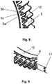
- the 8 and 9 show that the upper tooth parts 5 have radial heights 10 which are identical to radial depths 11 of the lower tooth parts 6, wherein the heights 10 and depths 11 are formed as distances projecting from the imaginary cylinder jacket surface 9 in the radially outward or inward direction.
- the heights 10 and the depths 11 can also be different in size.
- transition from a radial depth 11 to the imaginary concentric cylinder jacket surface 9 may be continuous or step-shaped, depending on the manufacturing process.
- the encoder wheel 1 is used for mounting on or on a crankshaft of an internal combustion engine for speed detection and / or for detecting a top dead center and / or for detecting a rotation angle.
- the passage 3, which receives the crankshaft, is seated with a press fit on the outer peripheral surface of the crankshaft.
- the recess 13, which in Fig. 1 is shown, is used to position the sender 1 in the correct position on the crankshaft.
- further attachment options are conceivable.
- the encoder wheel 1 has an inner ring 12 extending in the axial direction, which is arranged concentrically to the passage 3.
- the inner ring 12 can be pushed onto the outer peripheral surface of a shaft, not shown.
Landscapes
- Physics & Mathematics (AREA)
- General Physics & Mathematics (AREA)
- Transmission And Conversion Of Sensor Element Output (AREA)
- Shafts, Cranks, Connecting Bars, And Related Bearings (AREA)
Description
- Die Erfindung betrifft ein Geberrad nach dem Oberbegriff des Patentanspruchs 1.
- Bauteile zur Drehzahlerfassung einer Welle sind bereits aus dem Stand der Technik bekannt. Diese Bauteile dienen bei Verbrennungsmotoren der Erfassung des oberen und unteren Totpunkts einer Kurbelwelle sowie eines Drehwinkels der Kurbelwelle. Häufig verfügen diese Bauteile über eine Lücke oder Aussparung, um eine Kodierung zu erzeugen.
- Vor diesem Hintergrund ist aus der
EP 1 764 488 B1 bereits ein Geberrad bekannt, welches eine Zahnstruktur im Wesentlichen nach Art eines Zahnrads aufweist. Diese Zahnstruktur weist eine Vielzahl regelmäßiger einander umfänglich abfolgender Zahnteile und mindestens eine Unregelmäßigkeit in Form eines Plateaus auf. - Konkret ist aus der
EP 1 764 488 B1 ein Geberrad bekannt geworden, das zur Signalerzeugung eine gewellte Zahnstruktur aufweist, die obere und untere Zahnteile aufweist. Dieses Geberrad beansprucht einen relativ großen Bauraum in radialer Richtung und hat überdies ein hohes Gewicht. - Aus der
US 2002/0125882 A1 ist ein Geberrad bekannt, welches in dem Axialabschnitt mit Ausnehmungen versehen ist. - Aus der
JP 2002-13947 - Der Erfindung liegt daher die Aufgabe zugrunde, ein Geberrad der eingangs genannten Art derart auszugestalten und weiterzubilden, dass dieses bei möglichst geringem Gewicht in radialer Richtung platzsparend einsetzbar ist.
- Die vorliegende Erfindung löst die zuvor genannte Aufgabe durch die Merkmale des Patentanspruchs 1.
- Erfindungsgemäß ist zunächst erkannt worden, dass das Geberrad gemäß der
EP 1 764 488 B1 einen relativ großen Bauraum in radialer Richtung beansprucht, da dessen Zahnstruktur obere und untere Zahnteile aufweist, die sich über deren gesamte axiale Länge erstrecken. Darauf ist erkannt worden, dass durch axiale Verkürzung von Zahnteilen in radialer Richtung Bauraum eingespart werden kann. Durch das Verkürzen von Zahnteilen können sich diese in axialer Richtung nicht mehr weit erstrecken und daher nicht mehr an andere Bauteile anstoßen, die radial benachbart sind. Es wurde überraschend festgestellt, dass Bereiche von Zahnteilen für die Signalerzeugung auch gar nicht notwendig sind. Damit während der Fertigung des Geberrads dessen Robustheit, nämlich eine hohe Steifigkeit, erhalten bleibt, wird ein Zahnteil in axialer und radialer Richtung nur teilweise ausgespart. Dies erleichtert die Herstellbarkeit im Vergleich zur Ausbildung einer vollständigen Aussparung. Erfindungsgemäß wird Material nur an den Stellen eingesetzt, an denen es benötigt wird. Somit ist es möglich, radialen Bauraum zu verringern und Gewicht einzusparen. - Die unteren Zahnteile, nämlich die Wellentäler, sind erfindungsgemäß gegenüber den oberen Zahnteilen, also den Wellenbergen, in axialer Richtung verkürzt ausgebildet. Hierdurch wird in radialer Richtung nach innen Bauraum eingespart.
- Die oberen Zahnteile ragen über die unteren Zahnteile in axialer Richtung hinaus und sind im Querschnitt jeweils bogenförmig ausgebildet, wobei die beiden Endkanten eines jeden Bogens auf einer zu einem Durchgang konzentrischen gedachten Zylindermantelfläche aufliegen. Durch Einstellen des Verhältnisses der axialen Verkürzung eines unteren Zahnteils zur Länge eines oberen Zahnteils in axialer Richtung können die Steifigkeit des Geberrads sowie die Bauraumverringerung eingestellt werden.
- Die oberen Zahnteile könnten radiale Höhen aufweisen, die mit radialen Tiefen der unteren Zahnteile identisch sind, wobei die Höhen und Tiefen als von der gedachten Zylindermantelfläche in radialer Richtung nach außen bzw. innen abragende Strecken ausgebildet sind. Durch Einstellen des Verhältnisses Höhe zu Tiefe kann die Steifigkeit des Geberrads sowie die mit diesem erzielte Bauraumverringerung eingestellt werden.
- Die oberen Zahnteile könnten radiale Höhen aufweisen und die unteren Zahnteile könnten radiale Tiefen aufweisen, wobei die Höhen und Tiefen als von einer zu einem Durchgang konzentrischen gedachten Zylindermantelfläche in radialer Richtung nach außen bzw. innen abragende Strecken ausgebildet sind und wobei das Verhältnis Höhe geteilt durch Tiefe größer 0,3 und kleiner 30, bevorzugt größer 0,3 kleiner 10, besonders bevorzugt größer 0,3 kleiner 4, ist. Das erste Intervall bewirkt eine gute Signalqualität bei nahezu unverminderter Robustheit des Geberrads. Das zweite Intervall bewirkt eine noch ausreichende Signalqualität bei geringfügig verminderter Steifigkeit aber erhöhter Bauraumersparnis. Das dritte Intervall bewirkt eine hohe Bauraumersparnis.
- Es könnte eine Aussparung vorgesehen sein, welche der lagerichtigen Positionierung des Geberrads dient. Die Aussparung wird genutzt, um das Geberrad in Bezug auf einen oberen Totpunkt eines Verbrennungsmotors lagerichtig auf der Kurbelwelle zu positionieren.
- Das hier beschriebene Geberrad könnte zur Anordnung auf oder an einer Kurbelwelle eines Verbrennungsmotors zur Drehzahlerfassung und/ oder zur Erfassung eines oberen Totpunkts und/ oder zur Erfassung eines Drehwinkels verwendet werden.
- Das hier beschriebene Geberrad könnte auch in einem Verbrennungsmotor, der eine gasgeschmierte Gleitringdichtung aufweist, verwendet werden. Hierdurch kann Bauraum eingespart werden. Eine gasgeschmierte Gleitringdichtung dieser Art ist in der
DE 10 2011 114 349 A1 offenbart. - In der Zeichnung zeigen
- Fig. 1
- eine Draufsicht auf ein Geberrad,
- Fig. 2
- eine Schnittansicht des Geberrads gemäß
Fig. 1 nach der Schnittlinie B-B, - Fig. 3
- eine Schnittansicht des Geberrads gemäß
Fig. 1 nach der Schnittlinie C-C, - Fig. 4
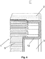
- eine Detailansicht des gestrichelten Kreises der
Fig. 3 , - Fig. 5
- eine Detailansicht des gestrichelten Kreises der
Fig. 2 , - Fig. 6
- eine perspektivische Ansicht des Geberrads gemäß
Fig. 1 , - Fig. 7
- eine weitere perspektivische Ansicht des Geberrads gemäß
Fig. 1 , - Fig. 8
- eine stark vergrößerte Darstellung der Zahnstruktur, wobei die sich nach radial außen erstreckende Höhe eines oberen Zahnteils dargestellt ist, und
- Fig. 9
- eine stark vergrößerte Darstellung der Zahnstruktur, wobei die sich nach radial innen erstreckende Tiefe eines unteren, axial verkürzten Zahnteils dargestellt ist.
-
Fig. 1 zeigt ein Geberrad 1, umfassend einen ringförmigen Grundkörper 2, der einen Durchgang 3 zum Durchgriff einer Welle aufweist, wobei vom Grundkörper 2 in axialer Richtung eine Zahnstruktur 4 abragt, wobei die Zahnstruktur 4 obere Zahnteile 5 und untere Zahnteile 6 aufweist, wobei die oberen Zahnteile 5 als Wellenberge und die unteren Zahnteile 6 als Wellentäler ausgestaltet sind. - Dieses Geberrad 1 ist auch in den
Fig. 6 und7 jeweils in perspektivischer Ansicht gezeigt. -
Fig. 1 zeigt, dass Unregelmäßigkeiten 7 in der Zahnstruktur 4 vorgesehen sind. Konkret sind einige unregelmäßige obere Zahnteile 5' als Doppelspitzen 8 ausgebildet. Dies dient dem in derEP 1 764 488 B1 beschriebenen Zweck.
Nachdem das Geberrad 1 lagerichtig auf einer Kurbelwelle eines Verbrennungsmotors positioniert wurde, können durch die zuvor genannten Unregelmäßigkeiten 7 der obere und untere Totpunkt des Verbrennungsmotors erfasst werden. -
Fig. 6 und7 zeigen, dass die unteren Zahnteile 6, nämlich die Wellentäler, und die oberen Zahnteile 5, also die Wellenberge, sich in axialer Richtung unterschiedlich weit erstrecken. Konkret zeigen dieFig. 6 und7 , dass die unteren Zahnteile 6, nämlich die Wellentäler, gegenüber den oberen Zahnteilen 5, also den Wellenbergen, in axialer Richtung verkürzt ausgebildet sind. - Konkret ragen die oberen Zahnteile 5 über die unteren Zahnteile 6 in axialer Richtung hinaus und sind im Querschnitt jeweils bogenförmig ausgebildet, wobei die beiden Endkanten 5a, 5b eines jeden Bogens 5c auf einer zum Durchgang 3 gedachten konzentrischen Zylindermantelfläche 9 aufliegen.
- Die
Fig. 8 und 9 zeigen, dass die oberen Zahnteile 5 radiale Höhen 10 aufweisen, die mit radialen Tiefen 11 der unteren Zahnteile 6 identisch sind, wobei die Höhen 10 und Tiefen 11 als von der gedachten Zylindermantelfläche 9 in radialer Richtung nach außen bzw. innen abragende Strecken ausgebildet sind. Die Höhen 10 und die Tiefen 11 können jedoch auch unterschiedlich groß sein. - Der Übergang von einer radialen Tiefe 11 zur gedachten konzentrischen Zylindermantelfläche 9 kann stetig oder stufenförmig ausgebildet sein, ganz in Abhängigkeit vom Fertigungsverfahren.
- Das Geberrad 1 wird zur Anordnung auf oder an einer Kurbelwelle eines Verbrennungsmotors zur Drehzahlerfassung und/ oder zur Erfassung eines oberen Totpunkts und/ oder zur Erfassung eines Drehwinkels verwendet.
- Der Durchgang 3, welcher die Kurbelwelle aufnimmt, sitzt mit einem Presssitz auf der äußeren Umfangsfläche der Kurbelwelle auf. Die Aussparung 13, welche in
Fig. 1 dargestellt ist, wird genutzt, um das Geberrad 1 lagerichtig auf der Kurbelwelle zu positionieren. Neben einem Presssitz sind weitere Befestigungsmöglichkeiten denkbar. - Das Geberrad 1 weist einen sich in axialer Richtung erstreckenden Innenkranz 12 auf, der konzentrisch zum Durchgang 3 angeordnet ist. Der Innenkranz 12 kann auf die äußere Umfangsfläche einer nicht gezeigten Welle aufgeschoben werden.
Claims (5)
- Geberrad (1), umfassend einen ringförmigen Grundkörper (2), der auf einer Welle befestigbar ist und einen Durchgang (3) zum Durchgriff einer Welle aufweist, wobei vom Grundkörper (2) in axialer Richtung eine Zahnstruktur (4) abragt, wobei die Zahnstruktur (4) obere Zahnteile (5) und untere Zahnteile (6) aufweist, wobei die oberen Zahnteile (5) als radiale Wellenberge und die unteren Zahnteile (6) als radiale Wellentäler ausgestaltet sind, wobei die unteren Zahnteile (6), nämlich die Wellentäler, und die oberen Zahnteile (5), also die Wellenberge, sich in axialer Richtung unterschiedlich weit erstrecken, dadurch gekennzeichnet, dass die unteren Zahnteile (6), nämlich die Wellentäler, gegenüber den oberen Zahnteilen (5), also den Wellenbergen, in axialer Richtung verkürzt ausgebildet sind, wobei die oberen Zahnteile (5) in ihrem in axialer Richtung vom Grundkörper abgewandten Endbereich über die unteren Zahnteile (6) in axialer Richtung hinausragen und im Querschnitt jeweils bogenförmig ausgebildet sind, wobei die beiden Endkanten (5a, 5b) eines jeden Bogens (5c) auf einer zum Durchgang (3) konzentrischen gedachten Zylindermantelfläche (9) aufliegen.
- Geberrad nach Anspruch 1, dadurch gekennzeichnet, dass die oberen Zahnteile (5) radiale Höhen (10) aufweisen und die unteren Zahnteile (6) radiale Tiefen (11) aufweisen, wobei die Höhen (10) und Tiefen (11) als von der Zylindermantelfläche (9) in radialer Richtung nach außen bzw. innen abragende Strecken ausgebildet sind und wobei das Verhältnis Höhe (10) geteilt durch Tiefe (11) größer 0,3 und kleiner 30, bevorzugt größer 0,3 kleiner 10, besonders bevorzugt größer 0,3 kleiner 4, ist.
- Geberrad nach einem der voranstehenden Ansprüche, dadurch gekennzeichnet, dass eine Aussparung (13) vorgesehen ist, welche der lagerichtigen Positionierung des Geberrads (1) dient.
- Verwendung eines Geberrads (1) nach einem der voranstehenden Ansprüche zur Anordnung auf oder an einer Kurbelwelle eines Verbrennungsmotors zur Drehzahlerfassung und/ oder zur Erfassung eines oberen Totpunkts und/ oder zur Erfassung eines Drehwinkels.
- Verwendung eines Geberrads nach einem der Ansprüche 1 bis 3 in einem Verbrennungsmotor, der eine gasgeschmierte Gleitringdichtung aufweist.
Applications Claiming Priority (1)
| Application Number | Priority Date | Filing Date | Title |
|---|---|---|---|
| DE102014015673.7A DE102014015673A1 (de) | 2014-10-24 | 2014-10-24 | Geberrad |
Publications (2)
| Publication Number | Publication Date |
|---|---|
| EP3012636A1 EP3012636A1 (de) | 2016-04-27 |
| EP3012636B1 true EP3012636B1 (de) | 2019-08-14 |
Family
ID=54325315
Family Applications (1)
| Application Number | Title | Priority Date | Filing Date |
|---|---|---|---|
| EP15188282.6A Active EP3012636B1 (de) | 2014-10-24 | 2015-10-05 | Geberrad |
Country Status (2)
| Country | Link |
|---|---|
| EP (1) | EP3012636B1 (de) |
| DE (1) | DE102014015673A1 (de) |
Families Citing this family (3)
| Publication number | Priority date | Publication date | Assignee | Title |
|---|---|---|---|---|
| DE102016006106B4 (de) * | 2016-05-13 | 2023-06-22 | Kaco Gmbh + Co. Kg | Gleitringdichtung |
| FR3078126A1 (fr) * | 2018-02-21 | 2019-08-23 | Valeo Embrayages | Roue phonique, procede de fabrication et dispositif rotatif equipe d'une telle roue |
| EP4281733B1 (de) | 2021-01-21 | 2024-09-18 | HELLA GmbH & Co. KGaA | Länglicher körper mit cursorband für ein fahrzeugsystem eines fahrzeugs |
Family Cites Families (11)
| Publication number | Priority date | Publication date | Assignee | Title |
|---|---|---|---|---|
| JPH0614058B2 (ja) * | 1988-08-18 | 1994-02-23 | 本田技研工業株式会社 | パルサーリングとその製造方法 |
| JPH0745014Y2 (ja) * | 1989-10-23 | 1995-10-11 | エヌティエヌ株式会社 | パルスリング |
| JPH04335111A (ja) * | 1991-05-10 | 1992-11-24 | Fanuc Ltd | 磁気抵抗形回転検出器 |
| DE4312424C2 (de) * | 1993-04-16 | 1997-04-24 | Iav Motor Gmbh | Gehäuseverschlußdeckel mit einer Drehzahlgebereinrichtung und einem dynamischen Dichtring |
| JPH1078442A (ja) * | 1996-07-10 | 1998-03-24 | Nissan Motor Co Ltd | 車輪速センサ用ロータ |
| JP2002013947A (ja) * | 2000-06-29 | 2002-01-18 | Press Kogyo Co Ltd | 回転検出用センサリング及びその製造方法 |
| US6498475B2 (en) * | 2001-03-06 | 2002-12-24 | Delphi Technologies, Inc. | Performance sensor ring with reduced mass |
| ATE419454T1 (de) | 2005-09-20 | 2009-01-15 | Freudenberg Carl Kg | Winkelmesseinrichtung |
| DE102007021421A1 (de) * | 2007-05-02 | 2008-11-06 | Kaco Gmbh + Co. Kg | Geberrad, vorzugsweise für Wellen, sowie Verfahren zur Herstellung eines solchen Geberrades |
| DE102011114349A1 (de) | 2010-09-30 | 2012-04-05 | Carl Freudenberg Kg | Gleitringdichtung |
| JP5199429B2 (ja) * | 2011-09-06 | 2013-05-15 | ファナック株式会社 | 回転検出器および回転検出器における回転子の製造方法 |
-
2014
- 2014-10-24 DE DE102014015673.7A patent/DE102014015673A1/de not_active Withdrawn
-
2015
- 2015-10-05 EP EP15188282.6A patent/EP3012636B1/de active Active
Non-Patent Citations (1)
| Title |
|---|
| None * |
Also Published As
| Publication number | Publication date |
|---|---|
| DE102014015673A1 (de) | 2016-04-28 |
| EP3012636A1 (de) | 2016-04-27 |
Similar Documents
| Publication | Publication Date | Title |
|---|---|---|
| EP2505880B2 (de) | Ölabstreifring | |
| EP2855981B1 (de) | Verfahren zur herstellung eines ölabstreifkolbenrings | |
| DE1956165A1 (de) | Wellen-Gleitringdichtung | |
| DE102016219919A1 (de) | Elastisches Zahnrad eines Wellgetriebes | |
| WO2014012532A1 (de) | Kolben für einen verbrennungsmotor | |
| WO2012152240A1 (de) | Kolbenring für 2-taktmotoren | |
| WO2017041800A1 (de) | Getriebe mit elastischem zahnrad | |
| DE102016004031A1 (de) | Freilauf und Verfahren zur Herstellung eines solchen Freilaufs | |
| EP3012636A1 (de) | Geberrad | |
| EP0692642A2 (de) | Scheibe und Anordnung eines Sicherungsrings mit einer Scheibe auf einer Welle | |
| DE102014225965A1 (de) | Fliehkraftpendel | |
| DE10252795B4 (de) | Kombinierter Stahlölabstreifring | |
| DE102016216592A1 (de) | Verstellvorrichtung für eine Welle | |
| DE102021204274A1 (de) | Hohlrad für einen Planetenradsatz eines Automatgetriebes eines Kraftfahrzeugs, Verbindungsanordnung mit dem Hohlrad sowie Fertigungsverfahren zur Herstellung des Hohlrads | |
| WO2017125346A1 (de) | Zahnrad, insbesondere für eine verbrennungskraftmaschine eines kraftahrzeugs | |
| EP3765309B1 (de) | Radnabe für ein fahrzeug | |
| DE102021205782A1 (de) | Loslageranordnung | |
| WO2011076178A2 (de) | Geberrad für eine kurbelwellenwinkel-sensoranordnung | |
| EP3359849B1 (de) | Kolbenring | |
| WO2015036401A1 (de) | Nockenwellenversteller | |
| AT522877B1 (de) | Lagerbock | |
| DE202013103113U1 (de) | Schildförmiges Flankenschutzelement und Schutzvorrichtung für einen Fahrzeugreifen | |
| AT520531B1 (de) | Zahnrad | |
| EP3049696B1 (de) | Kolben mit kolbenringnut, insbesondere kompressionsnut | |
| EP3273084B1 (de) | Synchronring |
Legal Events
| Date | Code | Title | Description |
|---|---|---|---|
| PUAI | Public reference made under article 153(3) epc to a published international application that has entered the european phase |
Free format text: ORIGINAL CODE: 0009012 |
|
| AK | Designated contracting states |
Kind code of ref document: A1 Designated state(s): AL AT BE BG CH CY CZ DE DK EE ES FI FR GB GR HR HU IE IS IT LI LT LU LV MC MK MT NL NO PL PT RO RS SE SI SK SM TR |
|
| AX | Request for extension of the european patent |
Extension state: BA ME |
|
| STAA | Information on the status of an ep patent application or granted ep patent |
Free format text: STATUS: REQUEST FOR EXAMINATION WAS MADE |
|
| 17P | Request for examination filed |
Effective date: 20161026 |
|
| RBV | Designated contracting states (corrected) |
Designated state(s): AL AT BE BG CH CY CZ DE DK EE ES FI FR GB GR HR HU IE IS IT LI LT LU LV MC MK MT NL NO PL PT RO RS SE SI SK SM TR |
|
| STAA | Information on the status of an ep patent application or granted ep patent |
Free format text: STATUS: EXAMINATION IS IN PROGRESS |
|
| 17Q | First examination report despatched |
Effective date: 20170808 |
|
| RIN1 | Information on inventor provided before grant (corrected) |
Inventor name: FEURER, GEORG Inventor name: NEUBERGER, SOEREN |
|
| RIN1 | Information on inventor provided before grant (corrected) |
Inventor name: FEURER, GEORG Inventor name: NEUBERGER, SOEREN |
|
| GRAP | Despatch of communication of intention to grant a patent |
Free format text: ORIGINAL CODE: EPIDOSNIGR1 |
|
| STAA | Information on the status of an ep patent application or granted ep patent |
Free format text: STATUS: GRANT OF PATENT IS INTENDED |
|
| RIC1 | Information provided on ipc code assigned before grant |
Ipc: G01D 5/244 20060101ALI20190402BHEP Ipc: G01D 5/14 20060101ALI20190402BHEP Ipc: G01P 3/488 20060101AFI20190402BHEP |
|
| INTG | Intention to grant announced |
Effective date: 20190426 |
|
| GRAS | Grant fee paid |
Free format text: ORIGINAL CODE: EPIDOSNIGR3 |
|
| GRAA | (expected) grant |
Free format text: ORIGINAL CODE: 0009210 |
|
| STAA | Information on the status of an ep patent application or granted ep patent |
Free format text: STATUS: THE PATENT HAS BEEN GRANTED |
|
| AK | Designated contracting states |
Kind code of ref document: B1 Designated state(s): AL AT BE BG CH CY CZ DE DK EE ES FI FR GB GR HR HU IE IS IT LI LT LU LV MC MK MT NL NO PL PT RO RS SE SI SK SM TR |
|
| REG | Reference to a national code |
Ref country code: GB Ref legal event code: FG4D Free format text: NOT ENGLISH |
|
| REG | Reference to a national code |
Ref country code: CH Ref legal event code: EP Ref country code: AT Ref legal event code: REF Ref document number: 1167660 Country of ref document: AT Kind code of ref document: T Effective date: 20190815 |
|
| REG | Reference to a national code |
Ref country code: IE Ref legal event code: FG4D Free format text: LANGUAGE OF EP DOCUMENT: GERMAN |
|
| REG | Reference to a national code |
Ref country code: DE Ref legal event code: R096 Ref document number: 502015009959 Country of ref document: DE |
|
| REG | Reference to a national code |
Ref country code: NL Ref legal event code: MP Effective date: 20190814 |
|
| REG | Reference to a national code |
Ref country code: LT Ref legal event code: MG4D |
|
| PG25 | Lapsed in a contracting state [announced via postgrant information from national office to epo] |
Ref country code: PT Free format text: LAPSE BECAUSE OF FAILURE TO SUBMIT A TRANSLATION OF THE DESCRIPTION OR TO PAY THE FEE WITHIN THE PRESCRIBED TIME-LIMIT Effective date: 20191216 Ref country code: NO Free format text: LAPSE BECAUSE OF FAILURE TO SUBMIT A TRANSLATION OF THE DESCRIPTION OR TO PAY THE FEE WITHIN THE PRESCRIBED TIME-LIMIT Effective date: 20191114 Ref country code: HR Free format text: LAPSE BECAUSE OF FAILURE TO SUBMIT A TRANSLATION OF THE DESCRIPTION OR TO PAY THE FEE WITHIN THE PRESCRIBED TIME-LIMIT Effective date: 20190814 Ref country code: SE Free format text: LAPSE BECAUSE OF FAILURE TO SUBMIT A TRANSLATION OF THE DESCRIPTION OR TO PAY THE FEE WITHIN THE PRESCRIBED TIME-LIMIT Effective date: 20190814 Ref country code: FI Free format text: LAPSE BECAUSE OF FAILURE TO SUBMIT A TRANSLATION OF THE DESCRIPTION OR TO PAY THE FEE WITHIN THE PRESCRIBED TIME-LIMIT Effective date: 20190814 Ref country code: LT Free format text: LAPSE BECAUSE OF FAILURE TO SUBMIT A TRANSLATION OF THE DESCRIPTION OR TO PAY THE FEE WITHIN THE PRESCRIBED TIME-LIMIT Effective date: 20190814 Ref country code: BG Free format text: LAPSE BECAUSE OF FAILURE TO SUBMIT A TRANSLATION OF THE DESCRIPTION OR TO PAY THE FEE WITHIN THE PRESCRIBED TIME-LIMIT Effective date: 20191114 Ref country code: NL Free format text: LAPSE BECAUSE OF FAILURE TO SUBMIT A TRANSLATION OF THE DESCRIPTION OR TO PAY THE FEE WITHIN THE PRESCRIBED TIME-LIMIT Effective date: 20190814 |
|
| PG25 | Lapsed in a contracting state [announced via postgrant information from national office to epo] |
Ref country code: AL Free format text: LAPSE BECAUSE OF FAILURE TO SUBMIT A TRANSLATION OF THE DESCRIPTION OR TO PAY THE FEE WITHIN THE PRESCRIBED TIME-LIMIT Effective date: 20190814 Ref country code: GR Free format text: LAPSE BECAUSE OF FAILURE TO SUBMIT A TRANSLATION OF THE DESCRIPTION OR TO PAY THE FEE WITHIN THE PRESCRIBED TIME-LIMIT Effective date: 20191115 Ref country code: ES Free format text: LAPSE BECAUSE OF FAILURE TO SUBMIT A TRANSLATION OF THE DESCRIPTION OR TO PAY THE FEE WITHIN THE PRESCRIBED TIME-LIMIT Effective date: 20190814 Ref country code: LV Free format text: LAPSE BECAUSE OF FAILURE TO SUBMIT A TRANSLATION OF THE DESCRIPTION OR TO PAY THE FEE WITHIN THE PRESCRIBED TIME-LIMIT Effective date: 20190814 Ref country code: RS Free format text: LAPSE BECAUSE OF FAILURE TO SUBMIT A TRANSLATION OF THE DESCRIPTION OR TO PAY THE FEE WITHIN THE PRESCRIBED TIME-LIMIT Effective date: 20190814 Ref country code: IS Free format text: LAPSE BECAUSE OF FAILURE TO SUBMIT A TRANSLATION OF THE DESCRIPTION OR TO PAY THE FEE WITHIN THE PRESCRIBED TIME-LIMIT Effective date: 20191214 |
|
| PG25 | Lapsed in a contracting state [announced via postgrant information from national office to epo] |
Ref country code: TR Free format text: LAPSE BECAUSE OF FAILURE TO SUBMIT A TRANSLATION OF THE DESCRIPTION OR TO PAY THE FEE WITHIN THE PRESCRIBED TIME-LIMIT Effective date: 20190814 |
|
| PG25 | Lapsed in a contracting state [announced via postgrant information from national office to epo] |
Ref country code: RO Free format text: LAPSE BECAUSE OF FAILURE TO SUBMIT A TRANSLATION OF THE DESCRIPTION OR TO PAY THE FEE WITHIN THE PRESCRIBED TIME-LIMIT Effective date: 20190814 Ref country code: EE Free format text: LAPSE BECAUSE OF FAILURE TO SUBMIT A TRANSLATION OF THE DESCRIPTION OR TO PAY THE FEE WITHIN THE PRESCRIBED TIME-LIMIT Effective date: 20190814 Ref country code: PL Free format text: LAPSE BECAUSE OF FAILURE TO SUBMIT A TRANSLATION OF THE DESCRIPTION OR TO PAY THE FEE WITHIN THE PRESCRIBED TIME-LIMIT Effective date: 20190814 Ref country code: DK Free format text: LAPSE BECAUSE OF FAILURE TO SUBMIT A TRANSLATION OF THE DESCRIPTION OR TO PAY THE FEE WITHIN THE PRESCRIBED TIME-LIMIT Effective date: 20190814 |
|
| PG25 | Lapsed in a contracting state [announced via postgrant information from national office to epo] |
Ref country code: MC Free format text: LAPSE BECAUSE OF FAILURE TO SUBMIT A TRANSLATION OF THE DESCRIPTION OR TO PAY THE FEE WITHIN THE PRESCRIBED TIME-LIMIT Effective date: 20190814 Ref country code: IS Free format text: LAPSE BECAUSE OF FAILURE TO SUBMIT A TRANSLATION OF THE DESCRIPTION OR TO PAY THE FEE WITHIN THE PRESCRIBED TIME-LIMIT Effective date: 20200224 Ref country code: CZ Free format text: LAPSE BECAUSE OF FAILURE TO SUBMIT A TRANSLATION OF THE DESCRIPTION OR TO PAY THE FEE WITHIN THE PRESCRIBED TIME-LIMIT Effective date: 20190814 Ref country code: SM Free format text: LAPSE BECAUSE OF FAILURE TO SUBMIT A TRANSLATION OF THE DESCRIPTION OR TO PAY THE FEE WITHIN THE PRESCRIBED TIME-LIMIT Effective date: 20190814 Ref country code: SK Free format text: LAPSE BECAUSE OF FAILURE TO SUBMIT A TRANSLATION OF THE DESCRIPTION OR TO PAY THE FEE WITHIN THE PRESCRIBED TIME-LIMIT Effective date: 20190814 |
|
| REG | Reference to a national code |
Ref country code: CH Ref legal event code: PL |
|
| REG | Reference to a national code |
Ref country code: DE Ref legal event code: R097 Ref document number: 502015009959 Country of ref document: DE |
|
| PLBE | No opposition filed within time limit |
Free format text: ORIGINAL CODE: 0009261 |
|
| STAA | Information on the status of an ep patent application or granted ep patent |
Free format text: STATUS: NO OPPOSITION FILED WITHIN TIME LIMIT |
|
| PG2D | Information on lapse in contracting state deleted |
Ref country code: IS |
|
| PG25 | Lapsed in a contracting state [announced via postgrant information from national office to epo] |
Ref country code: LI Free format text: LAPSE BECAUSE OF NON-PAYMENT OF DUE FEES Effective date: 20191031 Ref country code: CH Free format text: LAPSE BECAUSE OF NON-PAYMENT OF DUE FEES Effective date: 20191031 Ref country code: LU Free format text: LAPSE BECAUSE OF NON-PAYMENT OF DUE FEES Effective date: 20191005 |
|
| 26N | No opposition filed |
Effective date: 20200603 |
|
| REG | Reference to a national code |
Ref country code: BE Ref legal event code: MM Effective date: 20191031 |
|
| PG25 | Lapsed in a contracting state [announced via postgrant information from national office to epo] |
Ref country code: BE Free format text: LAPSE BECAUSE OF NON-PAYMENT OF DUE FEES Effective date: 20191031 Ref country code: SI Free format text: LAPSE BECAUSE OF FAILURE TO SUBMIT A TRANSLATION OF THE DESCRIPTION OR TO PAY THE FEE WITHIN THE PRESCRIBED TIME-LIMIT Effective date: 20190814 |
|
| GBPC | Gb: european patent ceased through non-payment of renewal fee |
Effective date: 20191114 |
|
| PG25 | Lapsed in a contracting state [announced via postgrant information from national office to epo] |
Ref country code: IE Free format text: LAPSE BECAUSE OF NON-PAYMENT OF DUE FEES Effective date: 20191005 Ref country code: GB Free format text: LAPSE BECAUSE OF NON-PAYMENT OF DUE FEES Effective date: 20191114 |
|
| PG25 | Lapsed in a contracting state [announced via postgrant information from national office to epo] |
Ref country code: CY Free format text: LAPSE BECAUSE OF FAILURE TO SUBMIT A TRANSLATION OF THE DESCRIPTION OR TO PAY THE FEE WITHIN THE PRESCRIBED TIME-LIMIT Effective date: 20190814 |
|
| PG25 | Lapsed in a contracting state [announced via postgrant information from national office to epo] |
Ref country code: HU Free format text: LAPSE BECAUSE OF FAILURE TO SUBMIT A TRANSLATION OF THE DESCRIPTION OR TO PAY THE FEE WITHIN THE PRESCRIBED TIME-LIMIT; INVALID AB INITIO Effective date: 20151005 Ref country code: MT Free format text: LAPSE BECAUSE OF FAILURE TO SUBMIT A TRANSLATION OF THE DESCRIPTION OR TO PAY THE FEE WITHIN THE PRESCRIBED TIME-LIMIT Effective date: 20190814 |
|
| REG | Reference to a national code |
Ref country code: AT Ref legal event code: MM01 Ref document number: 1167660 Country of ref document: AT Kind code of ref document: T Effective date: 20201005 |
|
| PG25 | Lapsed in a contracting state [announced via postgrant information from national office to epo] |
Ref country code: AT Free format text: LAPSE BECAUSE OF NON-PAYMENT OF DUE FEES Effective date: 20201005 |
|
| PG25 | Lapsed in a contracting state [announced via postgrant information from national office to epo] |
Ref country code: MK Free format text: LAPSE BECAUSE OF FAILURE TO SUBMIT A TRANSLATION OF THE DESCRIPTION OR TO PAY THE FEE WITHIN THE PRESCRIBED TIME-LIMIT Effective date: 20190814 |
|
| P01 | Opt-out of the competence of the unified patent court (upc) registered |
Effective date: 20230606 |
|
| PGFP | Annual fee paid to national office [announced via postgrant information from national office to epo] |
Ref country code: DE Payment date: 20251028 Year of fee payment: 11 |
|
| PGFP | Annual fee paid to national office [announced via postgrant information from national office to epo] |
Ref country code: IT Payment date: 20251022 Year of fee payment: 11 |
|
| PGFP | Annual fee paid to national office [announced via postgrant information from national office to epo] |
Ref country code: FR Payment date: 20251027 Year of fee payment: 11 |