EP3012615A1 - Container for optical measurement - Google Patents
Container for optical measurement Download PDFInfo
- Publication number
- EP3012615A1 EP3012615A1 EP14813409.1A EP14813409A EP3012615A1 EP 3012615 A1 EP3012615 A1 EP 3012615A1 EP 14813409 A EP14813409 A EP 14813409A EP 3012615 A1 EP3012615 A1 EP 3012615A1
- Authority
- EP
- European Patent Office
- Prior art keywords
- space
- container
- optical measurement
- side wall
- face
- Prior art date
- Legal status (The legal status is an assumption and is not a legal conclusion. Google has not performed a legal analysis and makes no representation as to the accuracy of the status listed.)
- Withdrawn
Links
- 238000005259 measurement Methods 0.000 title claims abstract description 80
- 230000003287 optical effect Effects 0.000 title claims abstract description 54
- 239000000463 material Substances 0.000 claims abstract description 18
- 239000007788 liquid Substances 0.000 claims description 47
- 238000005192 partition Methods 0.000 claims description 15
- 238000001914 filtration Methods 0.000 description 11
- 239000000428 dust Substances 0.000 description 7
- 239000002245 particle Substances 0.000 description 6
- 229920000515 polycarbonate Polymers 0.000 description 6
- 239000004417 polycarbonate Substances 0.000 description 6
- 239000004793 Polystyrene Substances 0.000 description 5
- 230000004048 modification Effects 0.000 description 5
- 238000012986 modification Methods 0.000 description 5
- -1 polyethylene Polymers 0.000 description 5
- 229920002223 polystyrene Polymers 0.000 description 5
- 239000012530 fluid Substances 0.000 description 4
- 239000004698 Polyethylene Substances 0.000 description 3
- 230000001678 irradiating effect Effects 0.000 description 3
- 229920000573 polyethylene Polymers 0.000 description 3
- BFSVOASYOCHEOV-UHFFFAOYSA-N 2-diethylaminoethanol Chemical compound CCN(CC)CCO BFSVOASYOCHEOV-UHFFFAOYSA-N 0.000 description 2
- 239000002033 PVDF binder Substances 0.000 description 2
- 239000004743 Polypropylene Substances 0.000 description 2
- 229920002678 cellulose Polymers 0.000 description 2
- 150000001925 cycloalkenes Chemical class 0.000 description 2
- 230000000694 effects Effects 0.000 description 2
- 239000003822 epoxy resin Substances 0.000 description 2
- 239000011521 glass Substances 0.000 description 2
- 238000004519 manufacturing process Methods 0.000 description 2
- 229920000647 polyepoxide Polymers 0.000 description 2
- 229920001155 polypropylene Polymers 0.000 description 2
- 229920002981 polyvinylidene fluoride Polymers 0.000 description 2
- 229920005989 resin Polymers 0.000 description 2
- 239000011347 resin Substances 0.000 description 2
- 230000035945 sensitivity Effects 0.000 description 2
- 241000894006 Bacteria Species 0.000 description 1
- 229910019142 PO4 Inorganic materials 0.000 description 1
- 239000000853 adhesive Substances 0.000 description 1
- 230000001070 adhesive effect Effects 0.000 description 1
- 239000011324 bead Substances 0.000 description 1
- 230000001413 cellular effect Effects 0.000 description 1
- 239000001913 cellulose Substances 0.000 description 1
- 230000000593 degrading effect Effects 0.000 description 1
- 239000000835 fiber Substances 0.000 description 1
- 239000011152 fibreglass Substances 0.000 description 1
- 239000010419 fine particle Substances 0.000 description 1
- 238000000703 high-speed centrifugation Methods 0.000 description 1
- 230000010354 integration Effects 0.000 description 1
- NBIIXXVUZAFLBC-UHFFFAOYSA-K phosphate Chemical compound [O-]P([O-])([O-])=O NBIIXXVUZAFLBC-UHFFFAOYSA-K 0.000 description 1
- 239000010452 phosphate Substances 0.000 description 1
- 238000000926 separation method Methods 0.000 description 1
Images


Classifications
-
- G—PHYSICS
- G01—MEASURING; TESTING
- G01N—INVESTIGATING OR ANALYSING MATERIALS BY DETERMINING THEIR CHEMICAL OR PHYSICAL PROPERTIES
- G01N21/00—Investigating or analysing materials by the use of optical means, i.e. using sub-millimetre waves, infrared, visible or ultraviolet light
- G01N21/01—Arrangements or apparatus for facilitating the optical investigation
- G01N21/03—Cuvette constructions
- G01N21/0303—Optical path conditioning in cuvettes, e.g. windows; adapted optical elements or systems; path modifying or adjustment
-
- B—PERFORMING OPERATIONS; TRANSPORTING
- B01—PHYSICAL OR CHEMICAL PROCESSES OR APPARATUS IN GENERAL
- B01L—CHEMICAL OR PHYSICAL LABORATORY APPARATUS FOR GENERAL USE
- B01L3/00—Containers or dishes for laboratory use, e.g. laboratory glassware; Droppers
- B01L3/50—Containers for the purpose of retaining a material to be analysed, e.g. test tubes
- B01L3/502—Containers for the purpose of retaining a material to be analysed, e.g. test tubes with fluid transport, e.g. in multi-compartment structures
- B01L3/5025—Containers for the purpose of retaining a material to be analysed, e.g. test tubes with fluid transport, e.g. in multi-compartment structures for parallel transport of multiple samples
- B01L3/50255—Multi-well filtration
-
- G—PHYSICS
- G01—MEASURING; TESTING
- G01N—INVESTIGATING OR ANALYSING MATERIALS BY DETERMINING THEIR CHEMICAL OR PHYSICAL PROPERTIES
- G01N21/00—Investigating or analysing materials by the use of optical means, i.e. using sub-millimetre waves, infrared, visible or ultraviolet light
- G01N21/01—Arrangements or apparatus for facilitating the optical investigation
- G01N21/03—Cuvette constructions
- G01N21/07—Centrifugal type cuvettes
-
- G—PHYSICS
- G01—MEASURING; TESTING
- G01N—INVESTIGATING OR ANALYSING MATERIALS BY DETERMINING THEIR CHEMICAL OR PHYSICAL PROPERTIES
- G01N21/00—Investigating or analysing materials by the use of optical means, i.e. using sub-millimetre waves, infrared, visible or ultraviolet light
- G01N21/62—Systems in which the material investigated is excited whereby it emits light or causes a change in wavelength of the incident light
- G01N21/63—Systems in which the material investigated is excited whereby it emits light or causes a change in wavelength of the incident light optically excited
- G01N21/64—Fluorescence; Phosphorescence
-
- B—PERFORMING OPERATIONS; TRANSPORTING
- B01—PHYSICAL OR CHEMICAL PROCESSES OR APPARATUS IN GENERAL
- B01L—CHEMICAL OR PHYSICAL LABORATORY APPARATUS FOR GENERAL USE
- B01L2300/00—Additional constructional details
- B01L2300/08—Geometry, shape and general structure
- B01L2300/0809—Geometry, shape and general structure rectangular shaped
-
- G—PHYSICS
- G01—MEASURING; TESTING
- G01N—INVESTIGATING OR ANALYSING MATERIALS BY DETERMINING THEIR CHEMICAL OR PHYSICAL PROPERTIES
- G01N2201/00—Features of devices classified in G01N21/00
- G01N2201/02—Mechanical
- G01N2201/022—Casings
Definitions
- the present invention relates to a container for optical measurement.
- a plate-separation type container for filtration including a plate having a bottom part provided with a filter, and a collection plate on which the plate is loaded detachably, which is configured to filter fluid loaded on the filter of the plate by suction with vacuum or high-speed centrifugation to the collection-plate side (see Patent Document 1, for example).
- the container for filtration of Patent Document 1 is configured so that the detachment of the plate makes the collection plate open to the above, and so for ultra-high sensitive optical measurement purposes, dust or the like in the air entering into the collection plate becomes noise source, thus degrading the measurement accuracy unfortunately.
- a container for optical measurement including: a container main body including a tubular-shaped side wall part having one end blocked with a bottom-face part and having the other end that is open, the side wall part being made up of a single member; and a filter that is fixed to an inner face of the side wall part so as to divide a space inside the side wall part into a side on the bottom-face part side and on a side of the other end that is open. At least a part of the container main body facing the space on the side of the bottom-face part is made of a material letting light pass therethrough.
- the space on the side of the bottom-face part which is defined by the filter that is fixed to an inner face of the side wall part that is made of a single member, defines a closed space that always communicates with the outside through the filter only. Then sample liquid is supplied to the space on the open-end side, and is moved to the space on the bottom-face side via the filter by centrifugal force or the like for filtration, resulting in the sample fluid, from which particles in size larger than that of the size of holes of the filter have been removed, being stored in the space on the bottom-face side.
- This enables ultra-high sensitive optical measurement for the sample liquid with less noise source because noise source for optical measurement has been removed, by irradiating the sample liquid in the space on the bottom-face side with light from the outside of the container main body.
- the side wall part is configured to be tubular made up of a single member, a user is not allowed to open the space on the bottom-face side to the air. Then, once particles such as noise source in the space are removed at the stage of manufacturing, ultra-high sensitive optical measurement can be performed accurately without the need for users of keeping and assembling the container for optical measurement under a clean environment.
- the "single member” does not have to be configured with a “single component”, which may include a plurality of components that are connected by bonding or other means for integration so as not to let a user disconnect them. In this way, this may be made of a single material or may be a joint member made of different materials.
- At least a part of the bottom-face part may be made of a material letting light pass therethrough.
- At least a part of the side wall part facing the space on the side of the bottom-face part may be made of a material letting light pass therethrough.
- the space on the side of the bottom-face part and the space on the other end side each may include a plurality of spaces divided in a direction intersecting the direction of an axis of the side wall part.
- sample liquid can be held in the plurality of spaces on the other-end side that are defined in the side wall part, whereby optical measurement of the sample liquid stored in the plurality of spaces on the bottom-face part side via the filter can be performed successively or at once. This can improve the work efficiency of optical measurement of the sample liquid.
- the above aspect further may include a partition wall that divides the space on the other end side in a direction intersecting the direction of an axis of the side wall part.
- sample liquid is supplied to the space on one side that is divided by the partition wall, while sample liquid is not applied to the space on the other side. Then when the sample liquid moves to the space on the bottom-face part side via the filter, air in the space on the bottom-face part side can be exhausted via the filter at the space on the other side to which the sample liquid is not supplied. This enables filtration to be performed smoothly.
- the partition wall may be connected to the filter in a liquid tight manner.
- optical measurement may be fluorescence measurement.
- Fluorescence measurement has high sensitivity and so is susceptible to noise source such as particles in the sample liquid. This configuration, however, enables ultra-high sensitive fluorescence measurement for sample liquid from which noise source has been removed.
- the present invention has the advantageous effect of enabling ultra-high sensitive optical measurement accurately without keeping the container under a clean environment.
- the container for optical measurement 1 includes a container main body 2 and a filter 3 that divides an internal space of the container main body 2.
- the container main body 2 includes a foursquare tubular-shaped side wall part 4 having one end blocked with a bottom-face part 5 and having the other end that is open, and being made up of a single member.
- the side wall part 4 is made of a liquid-tight material (e.g., polystyrene, polyethylene or polycarbonate).
- the side wall part 4 has a step-height 7 at its inner face at a part between the bottom-face part 5 and an opening part 6.
- a fitting member 41 is fitted to the step-height 7 from the above.
- the fitting member 41 is fitted to the side wall part 4 until it butts against the step-height 7.
- the fitting member 41 is made of a liquid-tight material (e.g., polystyrene, polyethylene or polycarbonate) like the side wall part 4.
- the side wall part 4 and the fitting member 41 are fitted, and their fitted faces are bonded with an adhesive over the entire faces.
- the bottom-face part 5 is made of a transparent and liquid-tight material (e.g., glass, polycarbonate, polypropylene, polystyrene, cycloolefin-based resin or epoxy resin).
- the bottom-face part 5 makes up a measurement part 51 to let light for measurement be incident therein from the outside and let fluorescence generated internally pass therethrough.
- the filter 3 is made up of a porous member for filtration (e.g., polyvinylidene fluoride (PVDF), mixed celluloseester (MCE), polycarbonate, cellulose phosphate, diethylethanolamine (DEAE) or fiberglass) having a large number of ultra-small holes.
- the size of the holes is smaller than that of noise source for fluorescence measurement, such as dust in the air (e.g., bacteria, house dust, fiber dust and pollen dust) and a foreign matter in the sample liquid (e.g., magnetic beads, dust coming from a living body such as cellular debris, and fine particles).
- the filter 3 is sandwiched between the step-height 7 of the side wall part 4 and the fitting member 41 to be fixed undetachably.
- the space 9 has one end at which the filter 3 is disposed and the other end that is open. Sample liquid can be supplied to the space 9 through the thus open opening part 6.
- the space 10 is surrounded with the filter 3, the side wall part 4 and the bottom-face part 5, which define a closed space that always communicates with the outside through the filter 3 only.
- the space 9 and the space 10 have substantially same volume or the space 9 has volume larger than that of the space 10.
- the container main body 2 is disposed so that the bottom-face part 5 is located below, and the sample liquid is supplied to the space 9 through the opening part 6 located above. Next, centrifugal force directed from the space 9 to the space 10 is applied so as to move the sample liquid from the inside of the space 9 to the space 10 via the filter 3.
- the space 10 can contain the sample liquid from which noise source has been removed. Then, light is applied to the sample liquid in the space 10 from an irradiation part (not illustrated) that is disposed below the bottom-face part 5 and externally of the container main body 2 via the bottom-face part 5 making up the measurement part 51.
- an irradiation part (not illustrated) that is disposed below the bottom-face part 5 and externally of the container main body 2 via the bottom-face part 5 making up the measurement part 51.
- the side wall part 4 is configured to be tubular made up of a single member, the space 10 cannot be open. This can lead to the advantage that, once particles such as noise source in the space 10 are removed at the stage of manufacturing, ultra-high sensitive fluorescence measurement can be performed accurately without the need for users of keeping and assembling the container for optical measurement 1 under a clean environment.
- fluorescence measurement is performed with light irradiated from the below of the bottom-face part 5, fluorescence measurement of the sample liquid can be performed easily irrespective of the amount of sample liquid stored in the space 10.
- the container for optical measurement 1 exemplifies the configuration of the bottom-face part 5 making up the measurement part 51, which is not a limiting example, and the measurement part 51 may be at least a part of the container main body 2 facing the space 10.
- a part of the side wall part 4 may be made of a transparent and liquid tight material (e.g., glass, polycarbonate, polypropylene, polystyrene, cycloolefin-based resin or epoxy resin).
- fluorescence measurement may be performed by irradiating sample liquid with light from an irradiation part (not illustrated) disposed laterally and outside of the container main body 2. This enables fluorescence measurement from the direction of the side face of the container main body 2 as well, when the measurement part 51 letting light pass therethrough is located below the fluid level of the sample liquid.
- the container for optical measurement 1 of the present embodiment has two spaces 9 and 10 divided in the container main body 2, which is not a limiting example.
- a container for optical measurement 12 has a space 9 that is divided by a partition wall 13 in the direction intersecting the axis X of the side wall part 4.
- the partition wall 13 is made of a liquid-tight material (e.g., polystyrene, polyethylene or polycarbonate). As illustrated in Figs. 3A and 3B , the partition wall 13 is disposed in the space 9 parallel to the axis x of the side wall part 4 so as to connect opposed inner faces 41a of the fitting member 41, and has one end extending to the position coming into contact with the filter 3, thus defining the space 9 into two spaces 14 and 15.
- a liquid-tight material e.g., polystyrene, polyethylene or polycarbonate
- sample liquid is supplied to the space 14 only on one side that is divided by the partition wall 13, to which centrifugal force is applied, thus moving sample liquid to the space 10 via the filter 3.
- air in the space 10 can be exhausted via the filter 3 at the space 15 on the other side, to which sample liquid is not supplied. This enables filtration to be performed smoothly.
- the partition wall 13 may be connected to the filter 3 in a liquid-tight manner.
- container for optical measurement 16 and 17 may have spaces 9 and 10 including a plurality of divided parts in the direction intersecting the axis X direction of the side wall part 4.
- sample liquid can be held in the plurality of spaces 9 that are defined in the side wall part 4, whereby fluorescence measurement of the sample liquid stored in the plurality of spaces 10 via the filter 3 can be performed successively or at once.
- Fig. 4 illustrates the container for optical measurement 1 having a plurality of spaces for each of the spaces 9 and 10
- Fig. 5 illustrates the container for optical measurement 12 having a plurality of spaces for each of the spaces 9, 14 and 15.
- the above exemplifies the case where centrifugal force is applied to the container for optical measurement 1 according to the present embodiment in the direction from the space 9 to the space 10, and instead of this, pressure may be applied thereto. Suction may be performed from the side of the space 15 of the containers for optical measurement 12 and 17, thus generating a difference in pressure between the space 9 and the space 10 to promote filtration of the sample liquid.
- the side wall part 4 may have a planar shape that is a cylindrical shape or a polygonal tubular shape instead of a foursquare tubular shape as illustrated in Figs. 1A and 3A as long as it has a tubular shape to define a space in the side wall part 4.
- the above-mentioned containers for optical measurement 12 and 17 exemplify the partition wall 13 that connects the opposed inner faces 41a of the fitting member 41.
- an L-letter shaped or a curved-face shaped partition wall 13 may be used so as to connect adjacent inner faces.
- the space 15 to circulate air may be sufficiently smaller than the space 14 into which sample liquid is to be supplied.
- the above-mentioned containers for optical measurement 1, 11, 12, 16 and 17 perform fluorescence measurement, which is not a limiting example, and they may be applied to any other optical measurement purposes.
- the above-mentioned containers for optical measurement 1, 11, 12, 16 and 17 include the side wall part 4 that is configured to be tubular made up of a single member made of a single material, which is not a limiting example.
- a plurality of components may be connected by bonding or other means so as not to let a user disconnect them, thus configuring the side wall part 4 to be tubular made up of a single member.
- these components may be made of the same material or different materials.
Landscapes
- Health & Medical Sciences (AREA)
- Chemical & Material Sciences (AREA)
- Analytical Chemistry (AREA)
- General Health & Medical Sciences (AREA)
- Immunology (AREA)
- Physics & Mathematics (AREA)
- Life Sciences & Earth Sciences (AREA)
- Biochemistry (AREA)
- General Physics & Mathematics (AREA)
- Pathology (AREA)
- Nuclear Medicine, Radiotherapy & Molecular Imaging (AREA)
- Clinical Laboratory Science (AREA)
- Chemical Kinetics & Catalysis (AREA)
- Hematology (AREA)
- Investigating, Analyzing Materials By Fluorescence Or Luminescence (AREA)
- Optical Measuring Cells (AREA)
- Investigating Or Analysing Materials By Optical Means (AREA)
Abstract
Description
- The present invention relates to a container for optical measurement.
- A plate-separation type container for filtration is known, including a plate having a bottom part provided with a filter, and a collection plate on which the plate is loaded detachably, which is configured to filter fluid loaded on the filter of the plate by suction with vacuum or high-speed centrifugation to the collection-plate side (see
Patent Document 1, for example). - [PTL 1]
JP 2004-4079 A - The container for filtration of
Patent Document 1 is configured so that the detachment of the plate makes the collection plate open to the above, and so for ultra-high sensitive optical measurement purposes, dust or the like in the air entering into the collection plate becomes noise source, thus degrading the measurement accuracy unfortunately. A user who uses the container for filtration ofPatent Document 1, therefore, has to keep the plate and the collection plate and assemble them under a clean environment with less dust, thus requiring a lot of facilities and labor. - In view of the above circumstance, it is an object of the present invention to provide a container for optical measurement capable of performing ultra-high sensitive optical measurement accurately without keeping the container under a clean environment.
- One aspect of the present invention provides a container for optical measurement, including: a container main body including a tubular-shaped side wall part having one end blocked with a bottom-face part and having the other end that is open, the side wall part being made up of a single member; and a filter that is fixed to an inner face of the side wall part so as to divide a space inside the side wall part into a side on the bottom-face part side and on a side of the other end that is open. At least a part of the container main body facing the space on the side of the bottom-face part is made of a material letting light pass therethrough.
- According to the present aspect, the space on the side of the bottom-face part, which is defined by the filter that is fixed to an inner face of the side wall part that is made of a single member, defines a closed space that always communicates with the outside through the filter only. Then sample liquid is supplied to the space on the open-end side, and is moved to the space on the bottom-face side via the filter by centrifugal force or the like for filtration, resulting in the sample fluid, from which particles in size larger than that of the size of holes of the filter have been removed, being stored in the space on the bottom-face side. This enables ultra-high sensitive optical measurement for the sample liquid with less noise source because noise source for optical measurement has been removed, by irradiating the sample liquid in the space on the bottom-face side with light from the outside of the container main body.
- In this case, since the side wall part is configured to be tubular made up of a single member, a user is not allowed to open the space on the bottom-face side to the air. Then, once particles such as noise source in the space are removed at the stage of manufacturing, ultra-high sensitive optical measurement can be performed accurately without the need for users of keeping and assembling the container for optical measurement under a clean environment.
- Herein the "single member" does not have to be configured with a "single component", which may include a plurality of components that are connected by bonding or other means for integration so as not to let a user disconnect them. In this way, this may be made of a single material or may be a joint member made of different materials.
- In the above aspect, at least a part of the bottom-face part may be made of a material letting light pass therethrough.
- This can facilitate optical measurement of sample liquid irrespective of the amount of sample liquid stored in the space on the bottom-face part side by irradiating the container main body disposed so that the bottom-face part is located below with light for measurement from the below of the bottom-face part.
- In the above aspect, at least a part of the side wall part facing the space on the side of the bottom-face part may be made of a material letting light pass therethrough.
- This enables optical measurement from the side face of the container main body as well, when the part made of a material letting light pass therethrough is located below the fluid level of the sample liquid.
- In the above aspect, the space on the side of the bottom-face part and the space on the other end side each may include a plurality of spaces divided in a direction intersecting the direction of an axis of the side wall part.
- With this configuration, sample liquid can be held in the plurality of spaces on the other-end side that are defined in the side wall part, whereby optical measurement of the sample liquid stored in the plurality of spaces on the bottom-face part side via the filter can be performed successively or at once. This can improve the work efficiency of optical measurement of the sample liquid.
- The above aspect further may include a partition wall that divides the space on the other end side in a direction intersecting the direction of an axis of the side wall part.
- With this configuration, sample liquid is supplied to the space on one side that is divided by the partition wall, while sample liquid is not applied to the space on the other side. Then when the sample liquid moves to the space on the bottom-face part side via the filter, air in the space on the bottom-face part side can be exhausted via the filter at the space on the other side to which the sample liquid is not supplied. This enables filtration to be performed smoothly.
- In the above aspect, the partition wall may be connected to the filter in a liquid tight manner.
- This can prevent sample liquid supplied to the space on one side from moving to the space, to which the sample is not supplied, via a gap between the partition wall and the filter. This can secure an air-exhaust passage during filtration of the sample liquid.
- In the above aspect, optical measurement may be fluorescence measurement.
- Fluorescence measurement has high sensitivity and so is susceptible to noise source such as particles in the sample liquid. This configuration, however, enables ultra-high sensitive fluorescence measurement for sample liquid from which noise source has been removed.
- The present invention has the advantageous effect of enabling ultra-high sensitive optical measurement accurately without keeping the container under a clean environment.
-
- [
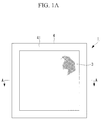
Fig. 1A] Fig. 1A is a plan view showing a container for optical measurement according to one embodiment of the present invention. - [
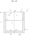
Fig. 1B] Fig. 1B is a vertical cross-sectional view along A-A of the container for optical measurement ofFig. 1A . - [
Fig. 2] Fig. 2 is a cross-sectional view showing one vertical cross section to illustrate a container for optical measurement according to a first modification example of the present invention. - [
Fig. 3A] Fig. 3A is a plan view showing a container for optical measurement according to a second modification example of the present invention. - [
Fig. 3B] Fig. 3B is a vertical cross-sectional view along B-B of the container for optical measurement ofFig. 3A . - [
Fig. 4] Fig. 4 is a plan view showing a container for optical measurement according to a third modification example of the present invention. - [
Fig. 5] Fig. 5 is a plan view showing a container for optical measurement according to a fourth modification example of the present invention. - [
Fig. 6] Fig. 6 is a plan view showing a container for optical measurement according to a fifth modification example of the present invention. - The following describes a container for
optical measurement 1 according to one embodiment of the present invention, with reference to the drawings. - As illustrated in
Figs. 1A and1B , the container foroptical measurement 1 according to the present embodiment includes a containermain body 2 and afilter 3 that divides an internal space of the containermain body 2. - As illustrated in
Figs. 1A and1B , the containermain body 2 includes a foursquare tubular-shapedside wall part 4 having one end blocked with a bottom-face part 5 and having the other end that is open, and being made up of a single member. Theside wall part 4 is made of a liquid-tight material (e.g., polystyrene, polyethylene or polycarbonate). - As illustrated in
Fig. 1B , theside wall part 4 has a step-height 7 at its inner face at a part between the bottom-face part 5 and anopening part 6. Afitting member 41 is fitted to the step-height 7 from the above. Thefitting member 41 is fitted to theside wall part 4 until it butts against the step-height 7. - The
fitting member 41 is made of a liquid-tight material (e.g., polystyrene, polyethylene or polycarbonate) like theside wall part 4. Theside wall part 4 and thefitting member 41 are fitted, and their fitted faces are bonded with an adhesive over the entire faces. - The bottom-
face part 5 is made of a transparent and liquid-tight material (e.g., glass, polycarbonate, polypropylene, polystyrene, cycloolefin-based resin or epoxy resin). The bottom-face part 5 makes up ameasurement part 51 to let light for measurement be incident therein from the outside and let fluorescence generated internally pass therethrough. - The
filter 3 is made up of a porous member for filtration (e.g., polyvinylidene fluoride (PVDF), mixed celluloseester (MCE), polycarbonate, cellulose phosphate, diethylethanolamine (DEAE) or fiberglass) having a large number of ultra-small holes. The size of the holes is smaller than that of noise source for fluorescence measurement, such as dust in the air (e.g., bacteria, house dust, fiber dust and pollen dust) and a foreign matter in the sample liquid (e.g., magnetic beads, dust coming from a living body such as cellular debris, and fine particles). Then thefilter 3 is sandwiched between the step-height 7 of theside wall part 4 and thefitting member 41 to be fixed undetachably. - This divides the space (space in the side wall part 4) of the container
main body 2 into a space 9 on the opening part 6 (the space on the other end side) and aspace 10 on the bottom-face part 5 side while setting thefilter 3 as the border. - As illustrated in
Fig. 1B , the space 9 has one end at which thefilter 3 is disposed and the other end that is open. Sample liquid can be supplied to the space 9 through the thusopen opening part 6. - As illustrated in
Fig. 1B , thespace 10 is surrounded with thefilter 3, theside wall part 4 and the bottom-face part 5, which define a closed space that always communicates with the outside through thefilter 3 only. - The space 9 and the
space 10 have substantially same volume or the space 9 has volume larger than that of thespace 10. - Functions of the thus configured container for
optical measurement 1 according to the present embodiment are described below. - When fluorescence measurement of sample liquid is performed using the container for
optical measurement 1 according to the present embodiment, the containermain body 2 is disposed so that the bottom-face part 5 is located below, and the sample liquid is supplied to the space 9 through theopening part 6 located above. Next, centrifugal force directed from the space 9 to thespace 10 is applied so as to move the sample liquid from the inside of the space 9 to thespace 10 via thefilter 3. - Since particles in the sample liquid having a size larger than the size of the holes of the
filter 3 cannot pass through the holes of thefilter 3 and remain in the space 9, thespace 10 can contain the sample liquid from which noise source has been removed. Then, light is applied to the sample liquid in thespace 10 from an irradiation part (not illustrated) that is disposed below the bottom-face part 5 and externally of the containermain body 2 via the bottom-face part 5 making up themeasurement part 51. Although fluorescence measurement has high sensitivity and so is susceptible to noise source such as particles in the sample liquid, the present embodiment enables ultra-high sensitive fluorescence measurement for sample liquid from which noise source has been removed. - In this case, since the
side wall part 4 is configured to be tubular made up of a single member, thespace 10 cannot be open. This can lead to the advantage that, once particles such as noise source in thespace 10 are removed at the stage of manufacturing, ultra-high sensitive fluorescence measurement can be performed accurately without the need for users of keeping and assembling the container foroptical measurement 1 under a clean environment. - Further since the fluorescence measurement is performed with light irradiated from the below of the bottom-
face part 5, fluorescence measurement of the sample liquid can be performed easily irrespective of the amount of sample liquid stored in thespace 10. - Since centrifugal force is applied in the direction from the space 9 to the
space 10, filtration of the sample liquid can be promoted as compared with the case of free-fall of the sample liquid held in the space 9 to thespace 10 due to its self weight. This can improve the work efficiency of fluorescence measurement for the sample liquid. - The container for
optical measurement 1 according to the present embodiment exemplifies the configuration of the bottom-face part 5 making up themeasurement part 51, which is not a limiting example, and themeasurement part 51 may be at least a part of the containermain body 2 facing thespace 10. For instance, as illustrated inFig. 2 , a part of theside wall part 4 may be made of a transparent and liquid tight material (e.g., glass, polycarbonate, polypropylene, polystyrene, cycloolefin-based resin or epoxy resin). Then, fluorescence measurement may be performed by irradiating sample liquid with light from an irradiation part (not illustrated) disposed laterally and outside of the containermain body 2. This enables fluorescence measurement from the direction of the side face of the containermain body 2 as well, when themeasurement part 51 letting light pass therethrough is located below the fluid level of the sample liquid. - The container for
optical measurement 1 of the present embodiment has twospaces 9 and 10 divided in the containermain body 2, which is not a limiting example. For instance, as illustrated inFigs. 3A and3B , a container foroptical measurement 12 has a space 9 that is divided by apartition wall 13 in the direction intersecting the axis X of theside wall part 4. - Specifically, the
partition wall 13 is made of a liquid-tight material (e.g., polystyrene, polyethylene or polycarbonate). As illustrated inFigs. 3A and3B , thepartition wall 13 is disposed in the space 9 parallel to the axis x of theside wall part 4 so as to connect opposedinner faces 41a of thefitting member 41, and has one end extending to the position coming into contact with thefilter 3, thus defining the space 9 into twospaces - In this case, sample liquid is supplied to the
space 14 only on one side that is divided by thepartition wall 13, to which centrifugal force is applied, thus moving sample liquid to thespace 10 via thefilter 3. At this time, air in thespace 10 can be exhausted via thefilter 3 at thespace 15 on the other side, to which sample liquid is not supplied. This enables filtration to be performed smoothly. - In the above-mentioned container for
optical measurement 12, thepartition wall 13 may be connected to thefilter 3 in a liquid-tight manner. - This can prevent sample liquid supplied to the
space 14 from moving to thespace 15 via a gap between thepartition wall 13 and thefilter 3. This can secure an air-exhaust passage during filtration of the sample liquid. - As illustrated in
Figs. 4 and 5 , as for these containers foroptical measurement optical measurement spaces 9 and 10 including a plurality of divided parts in the direction intersecting the axis X direction of theside wall part 4. - In this case, sample liquid can be held in the plurality of spaces 9 that are defined in the
side wall part 4, whereby fluorescence measurement of the sample liquid stored in the plurality ofspaces 10 via thefilter 3 can be performed successively or at once. This can improve the work efficiency of fluorescence measurement of the sample liquid.Fig. 4 illustrates the container foroptical measurement 1 having a plurality of spaces for each of thespaces 9 and 10, andFig. 5 illustrates the container foroptical measurement 12 having a plurality of spaces for each of thespaces - The above exemplifies the case where centrifugal force is applied to the container for
optical measurement 1 according to the present embodiment in the direction from the space 9 to thespace 10, and instead of this, pressure may be applied thereto. Suction may be performed from the side of thespace 15 of the containers foroptical measurement space 10 to promote filtration of the sample liquid. - In the above-mentioned containers for
optical measurement side wall part 4 may have a planar shape that is a cylindrical shape or a polygonal tubular shape instead of a foursquare tubular shape as illustrated inFigs. 1A and3A as long as it has a tubular shape to define a space in theside wall part 4. - The above-mentioned containers for
optical measurement partition wall 13 that connects the opposedinner faces 41a of thefitting member 41. Instead of this, as illustrated inFig. 6 , an L-letter shaped or a curved-face shapedpartition wall 13 may be used so as to connect adjacent inner faces. Thespace 15 to circulate air may be sufficiently smaller than thespace 14 into which sample liquid is to be supplied. - The above-mentioned containers for
optical measurement - The above-mentioned containers for
optical measurement side wall part 4 that is configured to be tubular made up of a single member made of a single material, which is not a limiting example. For instance, a plurality of components may be connected by bonding or other means so as not to let a user disconnect them, thus configuring theside wall part 4 to be tubular made up of a single member. In this case, these components may be made of the same material or different materials. -
- 1, 11, 12, 16, 17 container for optical measurement
- 2 container main body
- 3 filter
- 4 side wall part
- 5 bottom-face part
- 5C center of bottom-face part
- 6 opening part
- 6C center of opening part
- 7 step-height
- 9 space on the opening part side (space on the other side)
- 10 space on the bottom-face part side
- 13 partition wall
- 14 space on one side
- 15 space on the other side
- 41 fitting member
- 41a inner face of fitting member
- 51 measurement part
Claims (7)
- A container for optical measurement, comprising:a container main body comprising a tubular-shaped side wall part having one end blocked with a bottom-face part and having the other end that is open, the side wall part being made up of a single member; anda filter that is fixed to an inner face of the side wall part so as to divide a space inside the side wall part into a side on the bottom-face part side and on a side of the other end that is open; whereinat least a part of the container main body facing the space on the side of the bottom-face part is made of a material letting light pass therethrough.
- The container for optical measurement according to claim 1, wherein
at least a part of the bottom-face part is made of a material letting light pass therethrough. - The container for optical measurement according to claim 1, wherein
at least a part of the side wall part facing the space on the side of the bottom-face part is made of a material letting light pass therethrough. - The container for optical measurement according to any one of claims 1 to 3, wherein
the space on the side of the bottom-face part and the space on the other end side each include a plurality of spaces divided in a direction intersecting the direction of an axis of the side wall part. - The container for optical measurement according to any one of claims 1 to 4, further comprising a partition wall that divides the space on the other end side in a direction intersecting the direction of an axis of the side wall part.
- The container for optical measurement according to claim 5, wherein
the partition wall is connected to the filter in a liquid tight manner. - The container for optical measurement according to any one of claims 1 to 6, wherein
optical measurement is fluorescence measurement.
Applications Claiming Priority (2)
| Application Number | Priority Date | Filing Date | Title |
|---|---|---|---|
| JP2013128599 | 2013-06-19 | ||
| PCT/JP2014/064037 WO2014203693A1 (en) | 2013-06-19 | 2014-05-27 | Container for optical measurement |
Publications (2)
| Publication Number | Publication Date |
|---|---|
| EP3012615A1 true EP3012615A1 (en) | 2016-04-27 |
| EP3012615A4 EP3012615A4 (en) | 2017-03-08 |
Family
ID=52104435
Family Applications (1)
| Application Number | Title | Priority Date | Filing Date |
|---|---|---|---|
| EP14813409.1A Withdrawn EP3012615A4 (en) | 2013-06-19 | 2014-05-27 | Container for optical measurement |
Country Status (5)
| Country | Link |
|---|---|
| US (1) | US20150268155A1 (en) |
| EP (1) | EP3012615A4 (en) |
| JP (1) | JPWO2014203693A1 (en) |
| CN (1) | CN104823039B (en) |
| WO (1) | WO2014203693A1 (en) |
Families Citing this family (1)
| Publication number | Priority date | Publication date | Assignee | Title |
|---|---|---|---|---|
| JP6733861B2 (en) * | 2016-01-06 | 2020-08-05 | エア・ウォーター・バイオデザイン株式会社 | Component analysis system |
Family Cites Families (13)
| Publication number | Priority date | Publication date | Assignee | Title |
|---|---|---|---|---|
| JPS5770459A (en) * | 1980-10-22 | 1982-04-30 | Toshiba Corp | Cell cassette |
| US4725554A (en) * | 1981-06-16 | 1988-02-16 | Hoffmann-La Roche Inc. | Method for measuring blood coagulation time |
| CH653136A5 (en) * | 1981-06-16 | 1985-12-13 | Hoffmann La Roche | Method and device for measuring the clotting time of blood |
| US4865813A (en) * | 1986-07-07 | 1989-09-12 | Leon Luis P | Disposable analytical device |
| CA2055095C (en) * | 1990-11-09 | 2003-05-13 | Johnna B. Hawk | Column agglutination assay and device |
| US5264184A (en) * | 1991-03-19 | 1993-11-23 | Minnesota Mining And Manufacturing Company | Device and a method for separating liquid samples |
| DE59608443D1 (en) * | 1996-03-18 | 2002-01-24 | Diagnostische Forsch Stiftung | Particle immunoassay with a compact matrix |
| WO2001055727A1 (en) * | 2000-01-31 | 2001-08-02 | Emory University | Immunological assay system and method |
| US7214346B2 (en) * | 2001-02-07 | 2007-05-08 | Massachusetts Institute Of Technology | Optoelectronic detection system |
| US7211224B2 (en) | 2002-05-23 | 2007-05-01 | Millipore Corporation | One piece filtration plate |
| AU2006208907A1 (en) * | 2005-01-26 | 2006-08-03 | Enigma Diagnostics Ltd | Method for carrying out a multi-step reaction, breakable container for storing reagents and method for transferring solid reagent using an electrostatically charged wand |
| CN202256273U (en) * | 2010-05-26 | 2012-05-30 | 刘晓川 | Portable glycosylated hemoglobin instrument |
| US10012664B2 (en) * | 2011-09-25 | 2018-07-03 | Theranos Ip Company, Llc | Systems and methods for fluid and component handling |
-
2014
- 2014-05-27 EP EP14813409.1A patent/EP3012615A4/en not_active Withdrawn
- 2014-05-27 WO PCT/JP2014/064037 patent/WO2014203693A1/en not_active Ceased
- 2014-05-27 CN CN201480003252.8A patent/CN104823039B/en active Active
- 2014-05-27 JP JP2015522703A patent/JPWO2014203693A1/en active Pending
-
2015
- 2015-06-05 US US14/731,654 patent/US20150268155A1/en not_active Abandoned
Also Published As
| Publication number | Publication date |
|---|---|
| WO2014203693A1 (en) | 2014-12-24 |
| US20150268155A1 (en) | 2015-09-24 |
| CN104823039B (en) | 2017-09-12 |
| CN104823039A (en) | 2015-08-05 |
| JPWO2014203693A1 (en) | 2017-02-23 |
| EP3012615A4 (en) | 2017-03-08 |
Similar Documents
| Publication | Publication Date | Title |
|---|---|---|
| US10309876B2 (en) | Cartridge for airborne substance sensing device, and airborne substance sensing device | |
| US8440085B2 (en) | Plasma separation | |
| JP6246207B2 (en) | Method and apparatus for separating plasma from blood for bilirubin level estimation | |
| CN101031363B (en) | Microfluidic cartridge with reservoirs for increased shelf life of installed reagents | |
| CN109439525B (en) | Separation chip and manufacturing method thereof | |
| CN106164240B (en) | Cell trapping device, cell trapping filter, cell trapping device, and manufacturing method of cell trapping device | |
| US10919035B2 (en) | Microchip, analysis apparatus, and analysis method | |
| KR20220019059A (en) | Thick wall hollow fiber tangential flow filter | |
| CN105462834A (en) | Tumor cell capturing micro-fluidic chip and tumor cell capturing method | |
| WO2013108296A1 (en) | Subject selection device and subject selection method | |
| EP3012615A1 (en) | Container for optical measurement | |
| JP6438319B2 (en) | Particle detector | |
| WO2018020874A1 (en) | Cell strainer | |
| CN105891053B (en) | Particle detection device | |
| JP6863377B2 (en) | Cleaning method of fine particle measuring device and fine particle measuring device | |
| US9745568B2 (en) | Optofluidic microdevice for in-vitro laser surgery and transfection involving cells and microorganisms | |
| JP2026063671A (en) | Devices and test kits | |
| KR101965164B1 (en) | Apparatus for high-volume vacuum sampling of indoor dust by particle size | |
| CN208803057U (en) | Elution tube | |
| HK1194469A1 (en) | Leukocyte measurement device and reagent kit | |
| US20140318278A1 (en) | Particle imaging utilizing a filter | |
| WO2022185980A1 (en) | Particle fractionating kit | |
| JP2019049458A (en) | Blood filtration unit | |
| NZ600343B (en) | Plasma separation | |
| JP2008232785A (en) | Blood filter |
Legal Events
| Date | Code | Title | Description |
|---|---|---|---|
| PUAI | Public reference made under article 153(3) epc to a published international application that has entered the european phase |
Free format text: ORIGINAL CODE: 0009012 |
|
| 17P | Request for examination filed |
Effective date: 20160104 |
|
| AK | Designated contracting states |
Kind code of ref document: A1 Designated state(s): AL AT BE BG CH CY CZ DE DK EE ES FI FR GB GR HR HU IE IS IT LI LT LU LV MC MK MT NL NO PL PT RO RS SE SI SK SM TR |
|
| AX | Request for extension of the european patent |
Extension state: BA ME |
|
| DAX | Request for extension of the european patent (deleted) | ||
| RAP1 | Party data changed (applicant data changed or rights of an application transferred) |
Owner name: OLYMPUS CORPORATION |
|
| RIN1 | Information on inventor provided before grant (corrected) |
Inventor name: NAKATA, HIDETAKA |
|
| A4 | Supplementary search report drawn up and despatched |
Effective date: 20170203 |
|
| RIC1 | Information provided on ipc code assigned before grant |
Ipc: G01N 21/03 20060101AFI20170130BHEP Ipc: B01L 3/00 20060101ALI20170130BHEP Ipc: G01N 21/64 20060101ALI20170130BHEP Ipc: G01N 21/07 20060101ALI20170130BHEP |
|
| STAA | Information on the status of an ep patent application or granted ep patent |
Free format text: STATUS: REQUEST FOR EXAMINATION WAS MADE |
|
| STAA | Information on the status of an ep patent application or granted ep patent |
Free format text: STATUS: THE APPLICATION IS DEEMED TO BE WITHDRAWN |
|
| 18D | Application deemed to be withdrawn |
Effective date: 20170905 |