JP6863377B2 - Cleaning method of fine particle measuring device and fine particle measuring device - Google Patents
Cleaning method of fine particle measuring device and fine particle measuring device Download PDFInfo
- Publication number
- JP6863377B2 JP6863377B2 JP2018522327A JP2018522327A JP6863377B2 JP 6863377 B2 JP6863377 B2 JP 6863377B2 JP 2018522327 A JP2018522327 A JP 2018522327A JP 2018522327 A JP2018522327 A JP 2018522327A JP 6863377 B2 JP6863377 B2 JP 6863377B2
- Authority
- JP
- Japan
- Prior art keywords
- light
- unit
- photodetector
- measuring device
- fine particle
- Prior art date
- Legal status (The legal status is an assumption and is not a legal conclusion. Google has not performed a legal analysis and makes no representation as to the accuracy of the status listed.)
- Active
Links
Images


Classifications
-
- G—PHYSICS
- G01—MEASURING; TESTING
- G01N—INVESTIGATING OR ANALYSING MATERIALS BY DETERMINING THEIR CHEMICAL OR PHYSICAL PROPERTIES
- G01N15/00—Investigating characteristics of particles; Investigating permeability, pore-volume, or surface-area of porous materials
- G01N15/10—Investigating individual particles
- G01N15/14—Electro-optical investigation, e.g. flow cytometers
- G01N15/1456—Electro-optical investigation, e.g. flow cytometers without spatial resolution of the texture or inner structure of the particle, e.g. processing of pulse signals
- G01N15/1459—Electro-optical investigation, e.g. flow cytometers without spatial resolution of the texture or inner structure of the particle, e.g. processing of pulse signals the analysis being performed on a sample stream
-
- G—PHYSICS
- G01—MEASURING; TESTING
- G01N—INVESTIGATING OR ANALYSING MATERIALS BY DETERMINING THEIR CHEMICAL OR PHYSICAL PROPERTIES
- G01N15/00—Investigating characteristics of particles; Investigating permeability, pore-volume, or surface-area of porous materials
- G01N15/10—Investigating individual particles
- G01N15/14—Electro-optical investigation, e.g. flow cytometers
- G01N15/1434—Electro-optical investigation, e.g. flow cytometers using an analyser being characterised by its optical arrangement
-
- G—PHYSICS
- G01—MEASURING; TESTING
- G01N—INVESTIGATING OR ANALYSING MATERIALS BY DETERMINING THEIR CHEMICAL OR PHYSICAL PROPERTIES
- G01N15/00—Investigating characteristics of particles; Investigating permeability, pore-volume, or surface-area of porous materials
- G01N15/10—Investigating individual particles
- G01N15/14—Electro-optical investigation, e.g. flow cytometers
-
- G—PHYSICS
- G01—MEASURING; TESTING
- G01N—INVESTIGATING OR ANALYSING MATERIALS BY DETERMINING THEIR CHEMICAL OR PHYSICAL PROPERTIES
- G01N21/00—Investigating or analysing materials by the use of optical means, i.e. using sub-millimetre waves, infrared, visible or ultraviolet light
- G01N21/17—Systems in which incident light is modified in accordance with the properties of the material investigated
- G01N21/47—Scattering, i.e. diffuse reflection
- G01N21/49—Scattering, i.e. diffuse reflection within a body or fluid
- G01N21/53—Scattering, i.e. diffuse reflection within a body or fluid within a flowing fluid, e.g. smoke
Description
本技術は、微小粒子測定装置及び微小粒子測定装置の洗浄方法に関する。 The present technology relates to a fine particle measuring device and a cleaning method for the fine particle measuring device.
近年、再生医療・細胞治療の研究が盛んに進められており、細胞を迅速に評価する手法としてフローサイトメーターのニーズが高まっている。フローサイトメーターは、解析の対象となる微小粒子を流体中に整列させた状態で流し込み、該微小粒子にレーザー光等を照射することにより、各微小粒子から発せられた蛍光や散乱光を検出することで微小粒子の解析、分取を行う分析手法であり、再生医療・細胞治療の研究において細胞を解析するツールとして使用されている。これらの研究では、細胞が汚染されるリスクを低減する必要があるため、無菌環境で処理可能なフローサイトメーターが求められている。 In recent years, research on regenerative medicine and cell therapy has been actively promoted, and the need for a flow cytometer is increasing as a method for rapidly evaluating cells. The flow cytometer detects the fluorescence and scattered light emitted from each of the fine particles by pouring the fine particles to be analyzed into the fluid in an aligned state and irradiating the fine particles with laser light or the like. Therefore, it is an analysis method for analyzing and sorting fine particles, and is used as a tool for analyzing cells in research on regenerative medicine and cell therapy. These studies require a flow cytometer that can be processed in a sterile environment because of the need to reduce the risk of cell contamination.
例えば、特許文献1には、蛍光標識試薬などで染色された細胞をフローセル内で一列に配列するための流路系と、細胞にレーザー光を照射して散乱光や蛍光を検出するための光学系と、フローセル外の空間に吐出された液滴の移動方向を制御するための分取系と、からなるフローサイトメーター(微小粒子測定装置)が開示されている。
For example,
上述したような装置においては、液滴形成の際に発生するエアロゾル等の汚染物質が発生し、このエアロゾルが次のサンプルを汚染するというリスクがある。このような、サンプル間でのクロスコンタミネーションやサンプルの汚染等の問題は、特に、フローサイトメーターの分野では大きな障害となっている。 In the above-mentioned devices, there is a risk that pollutants such as aerosols generated during droplet formation are generated, and the aerosols contaminate the next sample. Such problems such as cross-contamination between samples and contamination of samples are major obstacles especially in the field of flow cytometers.
そこで、本技術では、コンタミネーションのリスクを低減可能な技術を提供することを主目的とする。 Therefore, the main purpose of this technology is to provide a technology that can reduce the risk of contamination.
本技術では、まず、分析対象となる微小粒子に対して光を照射する光照射部と、前記微小粒子から生じる光を所定の検出位置で検出する光検出部と、前記光検出部と接続され、前記光検出部で検出した光の検出値を解析する解析部と、を少なくとも有し、前記光検出部は、前記検出位置より移動可能である微小粒子測定装置を提供する。
本技術に係る微小粒子測定装置において、前記光検出部は、前方散乱光検出部であっても良い。
また、本技術に係る微小粒子測定装置において、前記検出位置は、前記微小粒子を挟んで前記光照射部と対向する位置であり、前記微小粒子から生じる光を検出可能なよう予め設定された位置であっても良い。
更に、本技術に係る微小粒子測定装置において、前記光検出部と接続し、所定の回転軸を定める回転軸部を更に有し、前記光検出部は、前記検出位置に対して前記所定の軸を中心として回転可能であっても良い。この場合、前記光検出部は、前記検出位置に対して前記所定の軸を中心として回転しながら上昇可能であっても良い。
加えて、本技術に係る微小粒子測定装置において、前記光検出部は、前記検出位置に対して水平方向又は上下方向のうち少なくとも一方向へ移動可能であっても良い。
また、本技術に係る微小粒子測定装置において、前記光照射部と前記解析部が格納された筐体を更に有し、前記光検出部は、前記筐体から完全分離可能であっても良い。
更に、本技術に係る微小粒子測定装置において、前記解析部は、前記光検出部と電気的に接続されていても良い。
加えて、本技術に係る微小粒子測定装置において、前記光検出部は、前記微小粒子から生じる光を受光する受光素子を有していても良い。この場合、前記光検出部は、前記光照射部と前記受光素子との間に配置され、前記微小粒子から生じる光を一部遮光する遮光部を有していても良い。
また、本技術に係る微小粒子測定装置において、前記光照射部と前記解析部が格納された筐体と、前記筐体に対して着脱可能なカバーと、を更に有し、前記光検出部は、前記カバーにより覆われることが可能であっても良い。In the present technology, first, a light irradiation unit that irradiates light on the fine particles to be analyzed, a light detection unit that detects the light generated from the fine particles at a predetermined detection position, and the light detection unit are connected. The photodetector provides a microparticle measuring device that has at least an analysis unit that analyzes the detected value of the light detected by the photodetector, and the photodetector is movable from the detection position.
In the microparticle measuring apparatus according to the present technology, the light detection unit may be a forward scattered light detection unit.
Further, in the microparticle measuring apparatus according to the present technology, the detection position is a position facing the light irradiation unit with the microparticles interposed therebetween, and is a preset position so that light generated from the microparticles can be detected. It may be.
Further, in the microparticle measuring device according to the present technology, the microparticle measuring device further has a rotation shaft portion that is connected to the light detection unit and determines a predetermined rotation axis, and the light detection unit further has the predetermined axis with respect to the detection position. It may be rotatable around. In this case, the photodetector may be able to ascend while rotating about the predetermined axis with respect to the detection position.
In addition, in the microparticle measuring apparatus according to the present technology, the light detection unit may be movable in at least one of the horizontal direction and the vertical direction with respect to the detection position.
Further, the microparticle measuring apparatus according to the present technology may further include a housing in which the light irradiation unit and the analysis unit are housed, and the light detection unit may be completely separable from the housing.
Further, in the microparticle measuring apparatus according to the present technology, the analysis unit may be electrically connected to the photodetection unit.
In addition, in the microparticle measuring apparatus according to the present technology, the photodetector may have a light receiving element that receives light generated from the microparticles. In this case, the light detection unit may be arranged between the light irradiation unit and the light receiving element, and may have a light shielding unit that partially blocks the light generated from the fine particles.
Further, in the microparticle measuring device according to the present technology, the light irradiation unit, the housing in which the analysis unit is housed, and a cover that can be attached to and detached from the housing are further provided, and the light detection unit further includes. , It may be possible to be covered by the cover.
また、本技術では、分析対象となる微小粒子に対して光を照射する光照射部と、前記微小粒子から生じる光を所定の検出位置で検出する光検出部と、前記光検出部と接続され、前記光検出部で検出した光の検出値を解析する解析部と、を少なくとも有し、前記光検出部は、前記検出位置より移動可能である微小粒子測定装置において、前記光検出部を、前記検出位置より移動させて、前記微小粒子測定装置を洗浄する微小粒子測定装置の洗浄方法も提供する。 Further, in the present technology, the light irradiation unit that irradiates the fine particles to be analyzed with light, the light detection unit that detects the light generated from the fine particles at a predetermined detection position, and the light detection unit are connected. The light detection unit has at least an analysis unit that analyzes the detected value of the light detected by the light detection unit, and the light detection unit is a microparticle measuring device that can move from the detection position. Also provided is a method for cleaning a fine particle measuring device, which is moved from the detection position to clean the fine particle measuring device.
本技術において、「微小粒子」には、細胞や微生物、リポソーム等の生体関連微小粒子、或いはラテックス粒子やゲル粒子、工業用粒子等の合成粒子などが広く含まれるものとする。 In the present technology, "fine particles" broadly include biological-related fine particles such as cells, microorganisms and liposomes, or synthetic particles such as latex particles, gel particles and industrial particles.
生体関連微小粒子には、各種細胞を構成する染色体、リポソーム、ミトコンドリア、オルガネラ(細胞小器官)などが含まれる。細胞には、動物細胞(例えば、血球系細胞など)及び植物細胞が含まれる。微生物には、大腸菌等の細菌類、タバコモザイクウイルス等のウイルス類、イースト菌等の菌類などが含まれる。更に、生体関連微小粒子には、核酸やタンパク質、これらの複合体等の生体関連高分子も包含され得る。また、工業用粒子は、例えば、有機又は無機高分子材料、金属等であっても良い。有機高分子材料には、ポリスチレン、スチレン・ジビニルベンゼン、ポリメチルメタクリレート等が含まれる。無機高分子材料には、ガラス、シリカ、磁性体材料等が含まれる。金属には、金コロイド、アルミ等が含まれる。これらの微小粒子の形状は、一般には球形であるのが普通であるが、本技術では、非球形であっても良く、また、その大きさ、質量等も特に限定されない。 Biologically-related microparticles include chromosomes, liposomes, mitochondria, organelles (organelles) and the like that make up various cells. Cells include animal cells (eg, blood cell lineage cells, etc.) and plant cells. Microorganisms include bacteria such as Escherichia coli, viruses such as tobacco mosaic virus, and fungi such as yeast. Further, the bio-related microparticles may include bio-related macromolecules such as nucleic acids, proteins, and complexes thereof. Further, the industrial particles may be, for example, an organic or inorganic polymer material, a metal or the like. Organic polymer materials include polystyrene, styrene / divinylbenzene, polymethylmethacrylate and the like. Inorganic polymer materials include glass, silica, magnetic materials and the like. Metals include colloidal gold, aluminum and the like. The shape of these fine particles is generally spherical, but in the present technology, they may be non-spherical, and their size, mass, and the like are not particularly limited.
本技術によれば、コンタミネーションのリスクを低減可能である。なお、ここに記載された効果は、必ずしも限定されるものではなく、本開示中に記載されたいずれかの効果であっても良い。 According to this technology, the risk of contamination can be reduced. The effects described here are not necessarily limited, and may be any of the effects described in the present disclosure.
以下、本技術を実施するための好適な形態について図面を参照しながら説明する。以下に説明する実施形態は、本技術の代表的な実施形態の一例を示したものであり、これにより本技術の範囲が狭く解釈されることはない。なお、説明は以下の順序で行う。
1.微小粒子測定装置100(第1実施形態及び第2実施形態)
(1)光照射部103
(2)光検出部104
(3)解析部105
2.微小粒子測定装置100(第3実施形態及び第4実施形態)
(1)流路P
(1−1)微小粒子測定用チップM
(1−2)フローセルP
(2)サンプル送液部101
(3)流体制御部102
(4)接続部材C
(5)光照射部103
(6)光検出部104
(7)解析部105
(8)分取部106(荷電部1061を含む)
(9)記憶部107
(10)表示部108
(11)入力部109
(12)制御部110
(13)その他
3.微小粒子測定装置の洗浄方法Hereinafter, suitable embodiments for carrying out the present technology will be described with reference to the drawings. The embodiments described below show an example of typical embodiments of the present technology, and the scope of the present technology is not narrowly interpreted by this. The explanation will be given in the following order.
1. 1. Fine particle measuring device 100 (first embodiment and second embodiment)
(1)
(2)
(3)
2. Fine particle measuring device 100 (third embodiment and fourth embodiment)
(1) Flow path P
(1-1) Chip M for measuring fine particles
(1-2) Flow cell P
(2) Sample
(3)
(4) Connection member C
(5)
(6)
(7)
(8) Sorting unit 106 (including charged unit 1061)
(9)
(10)
(11)
(12)
(13)
1.微小粒子測定装置100
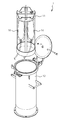
図1は、本技術に係る微小粒子測定装置100の第1実施形態を模式的に示す模式概念図である。
本技術に係る微小粒子測定装置100は、光照射部103と、光検出部104と、解析部105と、を少なくとも有するものである。また、必要に応じて、光照射部103と解析部105とを格納する筐体1000を更に備えていても良い。1. 1. Fine particle measuring device 100
FIG. 1 is a schematic conceptual diagram schematically showing a first embodiment of the fine particle measuring device 100 according to the present technology.
The fine particle measuring device 100 according to the present technology includes at least a
以下、各部について詳細に説明する。 Hereinafter, each part will be described in detail.
(1)光照射部103
光照射部103では、分析対象となる微小粒子に対して光を照射する。光照射部103から照射される光の種類は特に限定されないが、粒子から蛍光や散乱光を確実に発生させるためには、光方向、波長、光強度が一定の光が好ましい。具体的には、例えば、レーザー、LED等を挙げることができる。レーザーを用いる場合、その種類も特に限定されないが、アルゴンイオン(Ar)レーザー、ヘリウム−ネオン(He-Ne)レーザー、ダイ(dye)レーザー、クリプトン(Cr)レーザー、半導体レーザー、又は半導体レーザーと波長変換光学素子を組み合わせた固体レーザー等を1種又は2種以上自由に組み合わせて用いることができる。第1実施形態に示す微小粒子測定装置100では筐体1000内部に格納され配置される。一方で、筐体1000に格納されない場合には、以下に説明する光検出部104と同様に所定の照射位置から移動可能に構成することもできる。(1)
The
(2)光検出部104
光検出部104では、前記微小粒子から生じる光を所定の検出位置で検出する。第1の実施形態に係る微小粒子測定装置100では、光検出部104は、前記検出位置より移動可能であることを特徴とする。微小粒子が流れる周囲はエアロゾル等によるコンタミネーションのリスクが高く、この周囲に配置されている光検出部104や筐体1000等はサンプル毎に洗浄を行うことが望まれ、光検出部104を前記検出位置より移動させることで、この洗浄操作が可能となり、オペレータの負担が軽減する。(2)
The
また、エアロゾル等の汚染物質の除去もスムーズに行うことができることから、エアロゾルによるコンタミネーションのリスクや、オペレータへの感染・暴露等のバイオハザードのリスクも低減できる。 In addition, since pollutants such as aerosols can be smoothly removed, the risk of contamination by aerosols and the risk of biohazard such as infection / exposure to operators can be reduced.
本技術において、光検出部104は、流路内を通流する微小粒子に光を照射し、該照射により前記微小粒子から発生される蛍光(FL)、前方散乱光(FSC)及び後方散乱光(BSC)等の光成分を検出する。これらの蛍光及び必要な散乱光成分は、微小粒子の光学的情報(特性)を得る上で重要な光成分である。図2は、蛍光、前方散乱光、後方散乱光を受光する検出部を別体とした微小粒子測定装置100の第2の実施形態を模式的に示す概念図である。
In the present technology, the
前方散乱光検出部1041は、光源より出射された光(励起光)を照射された微小粒子から発生する前方散乱光を検出する。前方散乱光は、光源からの光の光軸に対して、一般的に、6°〜9°程度の角度で励起光を照射された微小粒子から散乱する光であり、主に微小粒子の大きさに関する情報が得られる。第2の実施形態における前方散乱光検出部1041は、図2に示すように、微小粒子を挟んで光照射部103と対抗する位置に配置することが望ましい。
The forward scattered
また、第2の実施形態における蛍光検出部1042は蛍光が照射光の入射方向とは異なる方向にも放射されることから、本技術では、例えば、流路Pを基準に光照射部103と同じ側や90度側面の側に、蛍光検出部1042を配置することも可能である。
Further, since the fluorescence detection unit 1042 in the second embodiment emits fluorescence in a direction different from the incident direction of the irradiation light, in the present technology, for example, it is the same as the
更に、第2の実施形態における後方散乱光検出部1043は、後方散乱光が照射光の光軸に対して約180°方向に微小粒子から散乱する光であることから、光照射部103と同じ側に配置することが望ましい。後方散乱光は、微小粒子の内部構造に関する情報が得られる散乱光であり、同様の情報が得られる散乱光として側方散乱光がある。側方散乱光は照射光の光軸に対して約90°方向に微小粒子から散乱する光であることから、微小粒子に対して光照射部103から直角の位置に配置されることが望ましい。
Further, the backscattered light detection unit 1043 in the second embodiment is the same as the
以上の通り、各光検出部は、微小粒子から生じる光を検出可能なよう予め設定された位置とすることができる。 As described above, each photodetector can be set at a preset position so that light generated from fine particles can be detected.
第2の実施形態で示す微小粒子測定装置100では、蛍光検出部1042、後方散乱光検出部1043は筐体1000に格納されていることから、前方散乱光検出部1041が移動可能であることが好ましい。一方でこの形態には限定されず、筐体1000がない場合には、全ての光検出部が移動可能であって良く、筐体1000の配置によっては前方散乱光検出部1041以外の光検出部のみが移動可能であっても良い。
In the fine particle measuring device 100 shown in the second embodiment, since the fluorescence detection unit 1042 and the backscattered light detection unit 1043 are housed in the
更に、本技術では、図3に示すように、光検出部104と接続し、所定の回転軸を定める回転軸部1011を更に有し、光検出部104は、前記検出位置に対して前記所定の軸を中心として回転可能であるものとすることができる。これにより、オペレータが容易に光検出部104を移動させることができる。この場合の回転角度は特に限定されず、例えば、図3に示すように、90°程度とすることができる。
Further, in the present technology, as shown in FIG. 3, the
この場合、光検出部104は、前記検出位置に対して前記所定の軸を中心として回転しながら上昇可能であっても良い。これにより、移動される光検出部104が、光検出部104の真下の面と擦れることを防ぐことができ、オペレータは容易に光検出部104を移動させることができる。
In this case, the
また、本技術では、光検出部104は、上述した回転移動により移動可能であるのみならず、前記検出位置に対して水平方向又は上下方向のうち少なくとも一方向へ移動可能であっても良い。
Further, in the present technology, the
また、本技術では、上述した少なくとも光照射部103と解析部105とを格納する筐体1000に対して、光検出部104を完全分離可能とすることができる。これにより、筐体1000の洗浄が容易となり、エアロゾル等によるコンタミネーションのリスクを低減できる。
Further, in the present technology, the
更に、本技術では、上述した筐体1000に対して着脱可能なカバーを有し、光検出部104は、前記カバーにより覆われることが可能であるものとすることができる。これにより、光検出部104に塵等のゴミなどが侵入することを防ぐことができる。
Further, in the present technology, it is possible to have a cover that can be attached to and detached from the
本技術では、光検出部104は、微小粒子からの光の検出ができれば、その種類は特に限定されず、公知の光検出器を自由に選択して採用することができる。例えば、蛍光測定器、散乱光測定器、透過光測定器、反射光測定器、回折光測定器、紫外分光測定器、赤外分光測定器、ラマン分光測定器、FRET測定器、FISH測定器、その他各種スペクトラム測定器、複数の光検出器をアレイ状に並べた、所謂、マルチチャンネル光検出器等を、1種又は2種以上自由に組み合わせて採用できる。
In the present technology, the type of the
また、本技術では、光検出部104は、前記微小粒子から生じる光を受光する受光素子を有することが好ましい。受光素子としては、CCDやCMOS素子等のエリア撮像素子、PMT、フォトダイオード等が挙げられる。
Further, in the present technology, it is preferable that the
更に、本技術では、光検出部104を異なる検出波長域を有する複数の受光素子から構成することもできる。光検出部104を異なる検出波長域を有する複数の受光素子から構成することで、連続した波長域における光の強度を蛍光スペクトルとして計測することができる。具体的には、例えば、受光素子を一次元に配列したPMTアレイ又はフォトダイオードアレイ、或いは、CCD又はCMOS等の2次元受光素子等の独立した検出チャネルが複数並べられたものが挙げられる。
Further, in the present technology, the
一方で、上述の移動式の光検出部104を採用した場合に、固定式の光検出部に比べると取付け位置の再現性の誤差が生じやすいことが分かった。例えば、固定式が20μm程度の誤差で固定されるのに対して、移動式は取付時に100μm程度の誤差が生じる可能性がある。この誤差が、結果として、測定誤差等に繋がる。
On the other hand, it was found that when the above-mentioned
更に、一般的に使用される光ファイバーを持つ光検出部では、移動時のダメージを含めて信頼性の心配がある。更に、この光ファイバーは、例えば、φ250μmのものを使った場合は、許容される誤差が50μm程度となり、取付位置の再現性の低い移動式の光検出部では、この許容範囲を超えて問題となるケースが想定される。 Further, in a commonly used photodetector having an optical fiber, there is a concern about reliability including damage during movement. Further, when this optical fiber is used, for example, with a diameter of 250 μm, the permissible error is about 50 μm, which becomes a problem in a mobile photodetector having low reproducibility of the mounting position, which exceeds this permissible range. A case is assumed.
また、光ファイバーとしてφ750μm程度の大口径のものを使えば、取付位置の再現性は確保できるが、その代わりに開口数(NA)の小さい光学系となり、焦点距離が長くなる関係から、装置自体が巨大化してしまう。 In addition, if a large-diameter optical fiber of about φ750 μm is used as the optical fiber, the reproducibility of the mounting position can be ensured, but instead, the optical system has a small numerical aperture (NA) and the focal length becomes long. It becomes huge.
別の方法として、コリメータレンズと集光レンズの倍率を調整して設計することも可能ではあるが、これには高NAで単焦点のレンズが必要となり、装置全体としてはコストアップとなる。 Alternatively, it is possible to design by adjusting the magnification of the collimator lens and the condenser lens, but this requires a high NA, single focus lens, which increases the cost of the entire device.
そこで、本技術における光検出部104では、レンズ光学系を使用することなく、直接受光素子PDへ照射する構成とすることが好ましい。例えば、図4で示した光検出部104は、受光素子PDと更に遮光部Sを有し、遮光部Sは光照射部103と受光素子PDとの間に配される。図4のAでは、後述する微小粒子測定用チップMに光照射部103から光が照射された際の様子を示す模式図であり、図4のBは、遮光部Sの形態の一例を示す模式図である。
Therefore, it is preferable that the
図4に示すように遮光部Sを介した散乱光を直接受光素子PDへ照射する構成とすることで、PDのサイズが、例えば、□10mmである場合は、そのずれ量自体は300μm程度のずれが存在したとしても、問題ないレベルとすることができる。 As shown in FIG. 4, by irradiating the light receiving element PD directly with the scattered light through the light-shielding portion S, when the size of the PD is, for example, □ 10 mm, the deviation amount itself is about 300 μm. Even if there is a deviation, it can be set to a level that does not cause any problem.
これにより、取付位置の誤差に起因する測定誤差を低減でき、装置自体の巨大化も抑制することができる。また、高価な光学部品を大きく削減でき、装置自体のコストダウンを図ることもできる。 As a result, the measurement error caused by the error of the mounting position can be reduced, and the enormous size of the device itself can be suppressed. In addition, expensive optical components can be greatly reduced, and the cost of the device itself can be reduced.
遮光部Sは、微小粒子から生じる光を遮ることができれば、その材質等は特に限定されない。また、遮光部Sの形態も特に限定されないが、例えば、図4のBで示したような形態とすることができる。 The material of the light-shielding portion S is not particularly limited as long as it can block the light generated from the fine particles. Further, the form of the light-shielding portion S is not particularly limited, but for example, the form shown in B of FIG. 4 can be used.
(3)解析部105
解析部105では、光検出部104と接続され、光検出部104で検出した微小粒子に対する光の検出値を解析する。その他にも解析部105では、各種の情報処理、並びに、光照射部103、光検出部104等の制御が行われても良い。(3)
The
本技術では、解析部105は、光検出部104と電気的に接続されているものとすることができる。これにより、光検出部104はより自由度を持って移動させることが可能となる。
In the present technology, the
解析部105では、例えば、光検出部104より受け取った光の検出値を補正し、各微小粒子の特徴量を算出することができる。具体的には、受光した蛍光、前方散乱光及び後方散乱光の検出値より微小粒子の大きさ、形態、内部構造等を示す特徴量を算出する。また、算出した特徴量と事前に入力部109より受け取った分取条件等に基づき分取判断を行い、分取制御信号を生成することもできる。
The
解析部105は、本技術に係る微小粒子測定装置100では必須ではなく、光検出部104によって検出された光の検出値に基づいて、外部の解析装置等を用いて微小粒子の状態等を解析することも可能である。例えば、解析部105は、パーソナルコンピュータや、CPUにて実施しても良く、更に記録媒体(不揮発性メモリ(USBメモリ等)、HDD、CD等)等を備えるハードウェア資源にプログラムとして格納し、パーソナルコンピュータやCPUによって機能させることも可能である。更に、解析部105は各部とネットワークを介して接続されていても良い。
The
2.微小粒子測定装置100
図5は、本技術に係る微小粒子測定装置100の第3実施形態を模式的に示す模式概念図であり、図6は、本技術に係る微小粒子測定装置100の第4実施形態を模式的に示す模式概念図である。本技術に係る微小粒子測定装置100は、必要に応じて、流路P、サンプル送液部101、流体制御部102、分取部106、荷電部1061、記憶部107、表示部108、入力部109、制御部110等を備えていても良い。2. Fine particle measuring device 100
FIG. 5 is a schematic conceptual diagram schematically showing a third embodiment of the fine particle measuring device 100 according to the present technology, and FIG. 6 is a schematic conceptual diagram showing a fourth embodiment of the fine particle measuring device 100 according to the present technology. It is a schematic conceptual diagram shown in. The microparticle measuring device 100 according to the present technology has a flow path P, a sample
図5中、サンプル送液部101からの送液が可能な送液チューブC11、シース液送液部1からの送液が可能な送液チューブC21、排液部3への排液が可能な排液チューブC41は、必要に応じて適宜取り外しが可能であり、これらの部材を使い捨て(ディスポーザブル)としても良い。更に、後述する微小粒子測定用チップMも、必要に応じて同様の取り扱いとすることができる。
In FIG. 5, the liquid feeding tube C11 capable of feeding liquid from the sample
以下、各部について詳細に説明する。 Hereinafter, each part will be described in detail.
(1)流路P
流路Pは、本技術に係る微小粒子測定装置100に予め備えていても良いが、市販の流路Pや流路Pが設けられた使い捨てのチップなどを、微小粒子測定装置100に設置して解析又は分取を行うことも可能である。(1) Flow path P
The flow path P may be provided in advance in the fine particle measuring device 100 according to the present technology, but a commercially available flow path P, a disposable chip provided with the flow path P, or the like is installed in the fine particle measuring device 100. It is also possible to perform analysis or sorting.
本技術に係る微小粒子測定装置100に用いることができる流路Pの形態は特に限定されず、自由に設計することができる。例えば、図5の微小粒子測定装置100に示すような2次元又は3次元のプラスチックやガラス等の基板内に形成した流路Pに限らず、図6の微小粒子測定装置100に示すように、従来のフローサイトメーターで用いられているようなフローセルからなる流路Pも、本技術に係る微小粒子測定装置100に用いることができる。 The form of the flow path P that can be used in the fine particle measuring device 100 according to the present technology is not particularly limited and can be freely designed. For example, it is not limited to the flow path P formed in the substrate such as two-dimensional or three-dimensional plastic or glass as shown in the fine particle measuring device 100 of FIG. 5, but as shown in the fine particle measuring device 100 of FIG. A flow path P made of a flow cell as used in a conventional flow cytometer can also be used in the fine particle measuring device 100 according to the present technology.
また、流路Pの流路幅、流路深さ、流路断面形状も、層流を形成し得る形態であれば特に限定されず、自由に設計することができる。例えば、流路幅1mm以下のマイクロ流路も、本技術に係る微小粒子測定装置100に用いることが可能である。特に、流路幅10μm以上1mm以下程度のマイクロ流路は、本技術に係る微小粒子測定装置100により好適に用いることができる。 Further, the flow path width, the flow path depth, and the flow path cross-sectional shape of the flow path P are not particularly limited as long as they can form a laminar flow, and can be freely designed. For example, a microchannel having a channel width of 1 mm or less can also be used in the microparticle measuring device 100 according to the present technology. In particular, a microchannel having a channel width of 10 μm or more and 1 mm or less can be suitably used by the fine particle measuring device 100 according to the present technology.
(1−1)微小粒子測定用チップM
図7は、図5の微小粒子測定装置100に使用可能な微小粒子測定用チップMの構成の一例を示す模式図であり、図8は、図5の微小粒子測定装置100に使用可能な微小粒子測定用チップMのオリフィスM1の構成の一例を示す模式図である。図7のAは上面模式図、図7のBはA中のP−P断面に対応する断面模式図を示す。また、図8のAは上面図、図8のBは断面図、図8のCは正面図を示す。なお、図8のBは、図7のA中のP−P断面に対応する。(1-1) Chip M for measuring fine particles
FIG. 7 is a schematic view showing an example of the configuration of the fine particle measuring chip M that can be used in the fine particle measuring device 100 of FIG. 5, and FIG. 8 is a schematic view showing an example of the configuration of the fine particle measuring chip M that can be used in the fine particle measuring device 100 of FIG. It is a schematic diagram which shows an example of the structure of the orifice M1 of the particle measurement chip M. A in FIG. 7 is a schematic top view, and B in FIG. 7 is a schematic cross-sectional view corresponding to the PP cross section in A. Further, A in FIG. 8 is a top view, B in FIG. 8 is a cross-sectional view, and C in FIG. 8 is a front view. Note that B in FIG. 8 corresponds to the PP cross section in A in FIG. 7.
微小粒子測定用チップMは、サンプル流路M2が形成された基板層Ma、Mbが貼り合わされてなる。基板層Ma、Mbへのサンプル流路M2の形成は、金型を用いた熱可塑性樹脂の射出成形により行うことができる。熱可塑性樹脂には、ポリカーボネート、ポリメタクリル酸メチル樹脂(PMMA)、環状ポリオレフィン、ポリエチレン、ポリスチレン、ポリプロピレン及びポリジメチルシロキサン(PDMS)等の、微小粒子測定用チップの材料として従来公知のプラスチックを採用できる。 The chip M for measuring fine particles is formed by laminating the substrate layers Ma and Mb on which the sample flow path M2 is formed. The sample flow path M2 can be formed on the substrate layers Ma and Mb by injection molding of a thermoplastic resin using a mold. As the thermoplastic resin, conventionally known plastics such as polycarbonate, polymethyl methacrylate resin (PMMA), cyclic polyolefin, polyethylene, polystyrene, polypropylene and polydimethylsiloxane (PDMS) can be used as materials for chips for measuring fine particles. ..
また、微小粒子測定用チップMには、微小粒子を含むサンプルを導入するサンプル導入部M3と、シース液を導入するシース導入部M4、サンプル流が導入されシース液と合流するサンプル流路M2が形成される。シース導入部M4から導入されたシース液は、2方向に分かれて送液された後、サンプル導入部M3から導入されたサンプル液との合流部において、サンプル液を2方向から挟み込むようにしてサンプル液に合流する。これにより、合流部において、シース液層流の中央にサンプル液層流が位置された3次元層流が形成される。 Further, the chip M for measuring fine particles includes a sample introduction unit M3 for introducing a sample containing fine particles, a sheath introduction unit M4 for introducing a sheath liquid, and a sample flow path M2 for introducing a sample flow and merging with the sheath liquid. It is formed. The sheath liquid introduced from the sheath introduction portion M4 is divided into two directions and then fed, and then the sample liquid is sandwiched from two directions at the confluence with the sample liquid introduced from the sample introduction portion M3. Join the liquid. As a result, a three-dimensional laminar flow in which the sample laminar flow is located in the center of the sheath laminar flow is formed at the confluence portion.
図7のAで示したM5は、サンプル流路M2に詰まりや気泡が生じた際に、サンプル流路M2内に負圧を加えて流れを一時的に逆流させて詰まりや気泡を解消するための吸引流路を示す。吸引流路M5の一端には、真空ポンプ等の負圧源に接続される吸引開口部M51が形成されている。また、吸引流路M5の他端は、連通口M52においてサンプル流路M2に接続している。 The M5 shown in FIG. 7A is for eliminating the clogging and bubbles by applying a negative pressure to the sample flow path M2 to temporarily reverse the flow when the sample flow path M2 is clogged or bubbles are generated. The suction flow path of is shown. A suction opening M51 connected to a negative pressure source such as a vacuum pump is formed at one end of the suction flow path M5. Further, the other end of the suction flow path M5 is connected to the sample flow path M2 at the communication port M52.
3次元層流は、送液方向に対する垂直断面の面積が送液方向上流から下流へ次第にあるいは段階的に小さくなるように形成された絞込部M61(図7参照)、M62(図8のA及びB参照)において層流幅を絞り込まれる。その後、3次元層流は、流路の一端に設けられたオリフィスM1から流体ストリームとなって排出される。 In the three-dimensional laminar flow, the narrowing portions M61 (see FIG. 7) and M62 (A in FIG. 8) are formed so that the area of the cross section perpendicular to the liquid feeding direction gradually or gradually decreases from the upstream to the downstream in the liquid feeding direction. And B), the laminar flow width is narrowed down. After that, the three-dimensional laminar flow is discharged as a fluid stream from the orifice M1 provided at one end of the flow path.
オリフィスM1から射出される流体ストリームは、以下に記述する振動素子106aがオリフィスM1に振動を印可することにより液滴化される。オリフィスM1は基板層Ma、Mbの端面方向に開口しており、その開口位置と基板層端面との間には切欠部M11が設けられている。切欠部M11は、オリフィスM1の開口位置と基板端面との間の基板層Ma、Mbを、切欠部M11の径L1がオリフィスM1の開口径L2よりも大きくなるように切り欠くことによって形成されている(図8のC参照)。切欠部M11の径L1は、オリフィスM1から吐出される液滴の移動を阻害しないように、オリフィスM1の開口径L2よりも2倍以上大きく形成されていることが好ましい。
The fluid stream ejected from the orifice M1 is atomized by the vibrating
(1−2)フローセルP
フローセルPは、サンプルを導入するサンプル導入部P3、シース液を導入するシース導入部P4、シース液とサンプルが合流しシース液層流の中央にサンプル液層流が位置された層流を構成する流路P2及びオリフィスP1とからなる。オリフィスP1からは流体ストリームが放出され、微小粒子測定装置が100備える以下に記述する光照射部103及び光検出部104により微小粒子の特性検出が行われる。(1-2) Flow cell P
The flow cell P constitutes a sample introduction portion P3 for introducing a sample, a sheath introduction portion P4 for introducing a sheath liquid, and a laminar flow in which the sheath liquid and the sample are merged and the sample liquid layer flow is located in the center of the sheath liquid layer flow. It consists of a flow path P2 and an orifice P1. A fluid stream is discharged from the orifice P1, and the characteristics of the fine particles are detected by the
(2)サンプル送液部101
サンプル送液部101は、サンプルを以下で説明するサンプル送液チューブ及びサンプル導入連結部C1を介して、サンプル導入部M3、P3へ送液する。例えば、サンプル送液部101は、サンプルを含む試験管又はウェルプレート等からノズルを介してサンプルを吸引・送液する、又は、サンプルを含む試験管等を格納可能な格納部に圧力をかけることでサンプルを送液することも可能である。(2) Sample
The sample
(3)流体制御部102
流体制御部102は、シース液導入部M4へシース液を導入するシース液送液部1を有する。図9は、シース液送液部1の実施形態の一例を示す模式図であり、シース液格納部10を取り付け可能な支持部11と密閉部12とを含む。例えば、シース液格納部10内のシース液は密閉部12に対する圧力により、上述したシース液送液チューブ2及びシース液導入連結部C2を介して、シース液導入部M4へ送液する。(3)
The
図10は、流体制御部102の実施形態の一例を示す模式図であり、流体制御部102は、更に排液部3を備える。例えば、ポンプ機能等により上述した排液チューブ及び排液連結部C4を介して吸引開口部M51からサンプル流路M2内の詰りや気泡等を回収する。また、排液部3は以下にて説明する分取部106において分取されなかった液滴やエアロゾル等を吸引するため、分取部106と接続することも可能である。
FIG. 10 is a schematic view showing an example of the embodiment of the
また、流体制御部102は、図10に示すように、シース液送液部1と排液部3とを設置可能な設置台4を備えても良い。排液制御部は、設置台4に設けることも可能であるが、以下に記述する制御部110の1つとして設置台4以外の場所に設けることも可能である。
Further, as shown in FIG. 10, the
更に、流体制御部102は、微小粒子測定装置100と別体に形成されても良いし、微小粒子測定装置100の一部として形成されても良い。
Further, the
(4)接続部材C
図11は、図5の微小粒子測定装置100において、微小粒子測定用チップMとサンプル送液部101・流体制御部102との間を接続する接続部材Cの実施形態の一例を示す模式図である。この実施形態の接続部材Cは、サンプル導入部M3に連結するサンプル導入連結部C1と、シース液導入部M4に連結するシース液導入連結部C2と、液滴の少なくとも一部に対して電荷を付与する荷電用電極部C3と、吸引開口部M51に連結する排液連結部C4を有し、サンプル導入連結部C1、シース液導入連結部C2及び排液連結部C4は、前記基板における各対応位置に連結するように位置決めされている。(4) Connection member C
FIG. 11 is a schematic view showing an example of an embodiment of a connecting member C that connects the fine particle measuring chip M and the sample
微小粒子測定用チップM及び微小粒子測定装置100に対して着脱自在な接続部材Cを用いることで、微小粒子測定用チップMと接触する箇所が取り外し可能となり、コンタミネーションのリスクを低減できる。また、前述した微小粒子測定用チップMや接続部材Cをサンプル毎に使い捨てにすることで、サンプルを変更する際に行われる洗浄操作の手間が省け、オペレータの負担を低減できる。 By using the connecting member C that can be attached to and detached from the fine particle measuring chip M and the fine particle measuring device 100, the portion that comes into contact with the fine particle measuring chip M can be removed, and the risk of contamination can be reduced. Further, by making the above-mentioned fine particle measuring chip M and the connecting member C disposable for each sample, the labor of the cleaning operation performed when changing the sample can be saved, and the burden on the operator can be reduced.
また、荷電用電極部C3は、シース液導入連結部C2と接触し、シース液を通じて前記液滴の少なくとも一部に対して電荷を付与するものとすることができる。荷電用電極部C3の構成は特に限定されないが、例えば、図12に示すように、荷電部1061と接続する接続部C31/C32と、シース液導入連結部C2と接触する接触部C33と、からなるものとすることができる。荷電部1061の詳細については、後述する(8)分取部106以下にて記載する。
Further, the charging electrode portion C3 can come into contact with the sheath liquid introduction connecting portion C2 and charge at least a part of the droplets through the sheath liquid. The configuration of the charging electrode portion C3 is not particularly limited, but for example, as shown in FIG. 12, from the connecting portion C31 / C32 connected to the charged
また、接続部C31/C32及び接触部C33は、金属からなるものとすることが好ましい。なお、これらの接続部C31/C32及び接触部C33に用いられる金属も、サンプル毎に使い捨てとすることで、サンプルを変更する際に行われる洗浄操作の手間が省け、オペレータの負担を低減できる。 Further, it is preferable that the connecting portion C31 / C32 and the contact portion C33 are made of metal. By disposing of the metal used for the connecting portion C31 / C32 and the contact portion C33 for each sample, the labor of the cleaning operation performed when changing the sample can be saved and the burden on the operator can be reduced.
また、シース液導入連結部C2は、図11及び12に示すように、シース液送液部1からの送液が可能な送液チューブC21、サンプル送液部101からの送液が可能な送液チューブC11、排液部3に排液可能な排液チューブC41を有していても良い。これらチューブも同様に微小粒子測定用チップM及び微小粒子測定装置100に対して着脱可能に構成され、サンプル毎に使い捨てにすることが可能である。
Further, as shown in FIGS. 11 and 12, the sheath liquid introduction connecting portion C2 is capable of feeding the liquid from the sheath
(5)光照射部103
光照射部103は、前述したものに対応するので、ここでは説明を割愛する。(5)
Since the
(6)光検出部104
光検出部104は、前述したものに対応するので、ここでは説明を割愛する。なお、図5及び図6では光検出部104を単体の光検出部として示したが、光検出部104は、複数の光検出部を含むことも可能である。(6)
Since the
(7)解析部105
解析部105は、前述したものに対応するので、ここでは説明を割愛する。(7)
Since the
(8)分取部106(荷電部1061を含む)
分取部106は、液滴を発生させる振動素子106a、荷電された液滴を所望の方向へ変更する偏向板106b、液滴を収集する収集容器を少なくとも有する。荷電部1061は図5及び6上、別途定義したが、分取部106の一部であり、解析部105により生成された分取制御信号に基づき荷電を行う。(8) Sorting unit 106 (including charged unit 1061)
The
図5で示した微小粒子測定装置100では、振動素子106aは上述した通りオリフィスM1に振動を加えることにより液滴を生成する。荷電部1061は上述したシース液流導入連結部C2と連結する荷電用電極部C3と接続し、微小粒子測定用チップMのオリフィスM1から吐出された液滴を解析部105により生成された分取制御信号に基づきプラス又はマイナスに荷電する。
In the fine particle measuring device 100 shown in FIG. 5, the vibrating
一方で、図6で示した微小粒子測定装置100では、振動素子106aはオリフィスM1から吐出される流体ストリームに振動を加えることにより液滴を生成し、荷電部1061は解析部105により生成された分取制御信号に基づき液滴をプラス又はマイナスに荷電する。
On the other hand, in the fine particle measuring device 100 shown in FIG. 6, the vibrating
そして、荷電された液滴は、電圧が印加された偏向板(対向電極)106bによって、その進路が所望の方向へ変更され、分取される。 Then, the path of the charged droplet is changed in a desired direction by the polarizing plate (opposite electrode) 106b to which the voltage is applied, and the charged droplet is sorted.
なお、用いる振動素子106aは特に限定されず、公知のものを自由に選択して用いることができる。一例としては、ピエゾ振動素子等を挙げることができる。また、流路Pへの送液量、吐出口の径、振動素子106aの振動数等を調整することにより、液滴の大きさを調整し、微小粒子を一定量ずつ含む液滴を発生させることができる。
The vibrating
(9)記憶部107
記憶部107では、光検出部104で検出された値、解析部105にて算出された特徴量、分取制御信号、入力部109にて入力された分取条件等の測定に関わるあらゆる事項を記憶する。(9)
In the
微小粒子測定装置100において、記憶部107は必須ではなく、外部の記憶装置を接続しても良い。記憶部107としては、例えば、ハードディスク等を用いることができる。更に、記憶部107は各部とネットワークを介して接続されていても良い。
In the fine particle measuring device 100, the
(10)表示部108
表示部108では、光検出部104で検出された値、解析部105にて算出された特徴量等の測定に関わるあらゆる事項を表示することができる。好ましくは、表示部108は、解析部105にて算出された各微小粒子に対する特徴量がスキャッタグラムとして表示することができる。(10)
The
微小粒子測定装置100において、表示部108は必須ではなく、外部の表示装置を接続しても良い。表示部108としては、例えば、ディスプレイ、プリンタ等を用いることができる。
In the fine particle measuring device 100, the
(11)入力部109
入力部109は、オペレータ等のユーザーが操作するための部位である。ユーザーは、入力部109を通じて、制御部110にアクセスし、本技術に係る微小粒子測定装置100の各部を制御することができる。好ましくは、入力部109は、表示部に表示されたスキャッタグラムに対して注目領域を設定し、分取条件を決定することが可能である。(11)
The
微小粒子測定装置100において、入力部109は必須ではなく、外部の操作装置を接続しても良い。入力部109としては、例えば、マウス、キーボード等を用いることができる。
In the fine particle measuring device 100, the
(12)制御部110
制御部110は、サンプル送液部101、流体制御部102、光照射部103、光検出部104、解析部105、分取部106、荷電部1061、記憶部107、表示部108及び入力部109のそれぞれを制御可能に構成されている。制御部110は各部に対して別々に配置されても良く、更に微小粒子測定装置100の外部に備えても良い。例えば、パーソナルコンピュータや、CPUにて実施しても良く、更に記録媒体(不揮発性メモリ(USBメモリ等)、HDD、CD等)等を備えるハードウェア資源にプログラムとして格納し、パーソナルコンピュータやCPUによって機能させることも可能である。更に、制御部110は各部とネットワークを介して接続されていても良い。(12)
The
(13)その他
本技術に係る微小粒子測定装置100は、バイオセーフティキャビネット内に格納可能である。バイオセーフティキャビネット内に格納することにより、ユーザーを含む周囲への飛散やサンプルの汚染を防止することが可能である。流体制御部102は、バイオセーフティキャビネット内に格納する必要はなく、バイオセーフティキャビネット壁面の開口部にて各チューブを介して微小粒子測定装置100と接続可能である。(13) Others The fine particle measuring device 100 according to the present technology can be stored in the biosafety cabinet. By storing it in the biosafety cabinet, it is possible to prevent scattering to the surroundings including the user and contamination of the sample. The
また、微小粒子測定装置100の各部は、サンプルの汚染を防止するため、洗浄可能に構成されている。特に、サンプルと接触する可能性のあるサンプル送液部101、流路P及び分取部106を含む筐体1000は洗浄可能に構成されていることが望ましい。
Further, each part of the fine particle measuring device 100 is configured to be washable in order to prevent contamination of the sample. In particular, it is desirable that the
3.微小粒子測定装置の洗浄方法
本技術に係る微小粒子測定装置の洗浄方法では、分析対象となる微小粒子に対して光を照射する光照射部103と、前記微小粒子から生じる光を所定の検出位置で検出する光検出部104と、光検出部104と接続され、光検出部104で検出した光の検出値を解析する解析部105と、を少なくとも有し、光検出部104は、前記検出位置より移動可能である微小粒子測定装置100において、光検出部104を、前記検出位置より移動させて、微小粒子測定装置100を洗浄する。微小粒子測定装置100や、光照射部103、光検出部104及び解析部105については、前述したものに対応するので、ここでは説明を割愛する。3. 3. Cleaning method of the fine particle measuring device In the cleaning method of the fine particle measuring device according to the present technology, the
なお、本技術では、以下の構成を取ることもできる。
(1)
分析対象となる微小粒子に対して光を照射する光照射部と、
前記微小粒子から生じる光を所定の検出位置で検出する光検出部と、
前記光検出部と接続され、前記光検出部で検出した光の検出値を解析する解析部と、
を少なくとも有し、
前記光検出部は、前記検出位置より移動可能である微小粒子測定装置。
(2)
前記光検出部は、前方散乱光検出部である、(1)に記載の微小粒子測定装置。
(3)
前記検出位置は、前記微小粒子を挟んで前記光照射部と対向する位置であり、前記微小粒子から生じる光を検出可能なよう予め設定された位置である、(1)又は(2)に記載の微小粒子測定装置。
(4)
前記光検出部と接続し、所定の回転軸を定める回転軸部を更に有し、
前記光検出部は、前記検出位置に対して前記所定の軸を中心として回転可能である、(1)から(3)のいずれかに記載の微小粒子測定装置。
(5)
前記光検出部は、前記検出位置に対して前記所定の軸を中心として回転しながら上昇可能である、(4)に記載の微小粒子測定装置。
(6)
前記光検出部は、前記検出位置に対して水平方向又は上下方向のうち少なくとも一方向へ移動可能である、(1)から(5)のいずれかに記載の微小粒子測定装置。
(7)
前記光照射部と前記解析部が格納された筐体を更に有し、
前記光検出部は、前記筐体から完全分離可能である、(1)から(6)のいずれかに記載の微小粒子測定装置。
(8)
前記解析部は、前記光検出部と電気的に接続されている、(1)から(7)のいずれかに記載の微小粒子測定装置。
(9)
前記光検出部は、前記微小粒子から生じる光を受光する受光素子を有する、(1)から(8)のいずれかに記載の微小粒子測定装置。
(10)
前記光検出部は、前記光照射部と前記受光素子との間に配置され、前記微小粒子から生じる光を一部遮光する遮光部を有する、(9)に記載の微小粒子測定装置。
(11)
前記光照射部と前記解析部が格納された筐体と、
前記筐体に対して着脱可能なカバーと、を更に有し、
前記光検出部は、前記カバーにより覆われることが可能である、(1)から(10)のいずれかに記載の微小粒子測定装置。
(12)
分析対象となる微小粒子に対して光を照射する光照射部と、前記微小粒子から生じる光を所定の検出位置で検出する光検出部と、前記光検出部と接続され、前記光検出部で検出した光の検出値を解析する解析部と、を少なくとも有し、前記光検出部は、前記検出位置より移動可能である微小粒子測定装置において、
前記光検出部を、前記検出位置より移動させて、前記微小粒子測定装置を洗浄する微小粒子測定装置の洗浄方法。The present technology can also have the following configurations.
(1)
A light irradiation unit that irradiates the fine particles to be analyzed with light,
A photodetector that detects light generated from the fine particles at a predetermined detection position,
An analysis unit that is connected to the photodetector and analyzes the detected value of the light detected by the photodetector.
Have at least
The photodetector is a microparticle measuring device that is movable from the detection position.
(2)
The microparticle measuring device according to (1), wherein the light detection unit is a forward scattered light detection unit.
(3)
The detection position is a position facing the light irradiation unit with the fine particles sandwiched between them, and is a preset position so that light generated from the fine particles can be detected, according to (1) or (2). Fine particle measuring device.
(4)
Further having a rotation shaft unit that is connected to the light detection unit and determines a predetermined rotation axis,
The microparticle measuring device according to any one of (1) to (3), wherein the photodetector is rotatable about the predetermined axis with respect to the detection position.
(5)
The microparticle measuring device according to (4), wherein the photodetector can ascend while rotating around the predetermined axis with respect to the detection position.
(6)
The microparticle measuring device according to any one of (1) to (5), wherein the photodetector can move in at least one of the horizontal direction and the vertical direction with respect to the detection position.
(7)
It further has a housing in which the light irradiation unit and the analysis unit are stored.
The microparticle measuring device according to any one of (1) to (6), wherein the photodetector is completely separable from the housing.
(8)
The fine particle measuring device according to any one of (1) to (7), wherein the analysis unit is electrically connected to the light detection unit.
(9)
The microparticle measuring device according to any one of (1) to (8), wherein the photodetector has a light receiving element that receives light generated from the microparticles.
(10)
The microparticle measuring apparatus according to (9), wherein the photodetector is arranged between the light irradiation unit and the light receiving element and has a light shielding portion that partially blocks light generated from the microparticles.
(11)
A housing in which the light irradiation unit and the analysis unit are stored,
It further has a cover that can be attached to and detached from the housing.
The microparticle measuring apparatus according to any one of (1) to (10), wherein the photodetector can be covered with the cover.
(12)
The light irradiation unit that irradiates the fine particles to be analyzed with light, the light detection unit that detects the light generated from the fine particles at a predetermined detection position, and the light detection unit are connected to the light detection unit. The light detection unit has at least an analysis unit that analyzes the detected value of the detected light, and the light detection unit is a microparticle measuring device that can move from the detection position.
A cleaning method for a fine particle measuring device in which the light detection unit is moved from the detection position to clean the fine particle measuring device.
100:微小粒子測定装置
101:サンプル送液部
102:流体制御部
103:光照射部
104:光検出部
1041:前方散乱光検出部
1042:蛍光検出部
1043:後方散乱光検出部
105:解析部
106:分取部
106a:振動素子
106b:偏向板
1061:荷電部
107:記憶部
108:表示部
109:入力部
110:制御部
111:光学フィルタ
1000:筐体
1011:回転軸部
1:シース液送液部
10:シース液格納部
11:支持部
12:密閉部
2:シース液送液チューブ
3:排液部
4:設置台
P:流路
R1:レーザー光線
R2:散乱光
BSC:後方散乱光
FL:蛍光
FSC:前方散乱光
S:遮光部
PD:受光素子
M:微小粒子測定用チップ
Ma、Mb:基板層
M1:オリフィス
M11:切欠部
M2:サンプル流路
M3:サンプル導入部
M4:シース導入部
M5:吸引流路
M51:吸引開口部
M52:連通口
M61、M62:絞込部
M7:ストレート部
L1:切欠部M11の径
L2:オリフィスM1の開口径
C:接続部材
C1:サンプル導入連結部
C11:サンプル送液部からの送液が可能な送液チューブ
C111:チューブ固定部
C2:シース液導入連結部
C21:シース液送液部からの送液が可能な送液チューブ
C3:荷電用電極部
C31、C32:接続部
C33:接触部
C4:排液連結部
C41:排液部への排液が可能な排液チューブ100: Fine particle measuring device 101: Sample liquid feeding unit 102: Fluid control unit 103: Light irradiation unit 104: Light detection unit 1041: Forward scattered light detection unit 1042: Fluorescence detection unit 1043: Backscattered light detection unit 105: Analysis unit 106: Sorting unit 106a: Vibrating element 106b: Deflection plate 1061: Charged unit 107: Storage unit 108: Display unit 109: Input unit 110: Control unit 111: Optical filter 1000: Housing 1011: Rotating shaft unit 1: Sheath fluid Liquid feeding part 10: Sheath liquid storage part 11: Support part 12: Sealing part 2: Sheath liquid feeding tube 3: Liquid draining part 4: Installation table P: Flow path R1: Laser beam R2: Scattered light BSC: Backscattered light FL : Fluorescent FSC: Forward scattered light S: Light-shielding part PD: Light-receiving element M: Chip for measuring fine particles Ma, Mb: Substrate layer M1: Orifice M11: Notch part M2: Sample flow path M3: Sample introduction part M4: Sheath introduction part M5: Suction flow path M51: Suction opening M52: Communication port M61, M62: Narrowing part M7: Straight part L1: Notch M11 diameter L2: Orifice M1 opening diameter C: Connecting member C1: Sample introduction connecting part C11 : Liquid feeding tube C111 capable of feeding liquid from the sample liquid feeding part: Tube fixing part C2: Sheath liquid introduction connecting part C21: Liquid feeding tube capable of feeding liquid from the sheath liquid feeding part C3: Electrod part for charging C31, C32: Connection part C33: Contact part C4: Drainage connection part C41: Drainage tube capable of draining liquid to the drainage part
Claims (10)
前記微小粒子から生じる光を所定の検出位置で検出する光検出部と、
前記光検出部と接続され、前記光検出部で検出した光の検出値を解析する解析部と、
を少なくとも有し、
前記光検出部は、前記検出位置より移動可能であり、
前記光検出部と接続し、所定の回転軸を定める回転軸部を更に有し、
前記光検出部は、前記検出位置に対して前記所定の軸を中心として回転可能である、微小粒子測定装置。 A light irradiation unit that irradiates the fine particles to be analyzed with light,
A photodetector that detects light generated from the fine particles at a predetermined detection position,
An analysis unit that is connected to the photodetector and analyzes the detected value of the light detected by the photodetector.
Have at least
The photo detecting portion is Ri movable der than the detection position,
Further having a rotation shaft unit that is connected to the light detection unit and determines a predetermined rotation axis,
The photodetector is a microparticle measuring device that is rotatable about the predetermined axis with respect to the detection position.
前記光検出部は、前記筐体から完全分離可能である、請求項1から5のいずれか一項に記載の微小粒子測定装置。 It further has a housing in which the light irradiation unit and the analysis unit are stored.
The microparticle measuring device according to any one of claims 1 to 5 , wherein the photodetector is completely separable from the housing.
前記筐体に対して着脱可能なカバーと、を更に有し、
前記光検出部は、前記カバーにより覆われることが可能である、請求項1から9のいずれか一項に記載の微小粒子測定装置。
A housing in which the light irradiation unit and the analysis unit are stored,
It further has a cover that can be attached to and detached from the housing.
The microparticle measuring apparatus according to any one of claims 1 to 9 , wherein the photodetector can be covered with the cover.
Applications Claiming Priority (3)
| Application Number | Priority Date | Filing Date | Title |
|---|---|---|---|
| JP2016116693 | 2016-06-10 | ||
| JP2016116693 | 2016-06-10 | ||
| PCT/JP2017/008877 WO2017212718A1 (en) | 2016-06-10 | 2017-03-07 | Fine particle measurement device and method for cleaning fine particle measurement device |
Publications (2)
| Publication Number | Publication Date |
|---|---|
| JPWO2017212718A1 JPWO2017212718A1 (en) | 2019-04-04 |
| JP6863377B2 true JP6863377B2 (en) | 2021-04-21 |
Family
ID=60577740
Family Applications (1)
| Application Number | Title | Priority Date | Filing Date |
|---|---|---|---|
| JP2018522327A Active JP6863377B2 (en) | 2016-06-10 | 2017-03-07 | Cleaning method of fine particle measuring device and fine particle measuring device |
Country Status (4)
| Country | Link |
|---|---|
| US (1) | US11112345B2 (en) |
| JP (1) | JP6863377B2 (en) |
| DE (1) | DE112017002897B4 (en) |
| WO (1) | WO2017212718A1 (en) |
Family Cites Families (13)
| Publication number | Priority date | Publication date | Assignee | Title |
|---|---|---|---|---|
| US4952055A (en) * | 1988-10-03 | 1990-08-28 | Wyatt Technology Corporation | Differential refractometer |
| JPH0336944U (en) * | 1989-08-22 | 1991-04-10 | ||
| JP3635901B2 (en) | 1997-12-10 | 2005-04-06 | 富士電機システムズ株式会社 | Forward scattered light receiving optical system and manufacturing method thereof |
| JP4320924B2 (en) | 1999-06-15 | 2009-08-26 | 東京エレクトロン株式会社 | Particle measuring device and processing device |
| US20040083798A1 (en) * | 2002-11-05 | 2004-05-06 | Sadar Michael J. | Detection of filter breakthrough |
| JP4756948B2 (en) | 2005-08-08 | 2011-08-24 | ベイバイオサイエンス株式会社 | Flow cytometer and flow cytometry method |
| JP2008096155A (en) * | 2006-10-06 | 2008-04-24 | National Institute Of Advanced Industrial & Technology | Fine particle detector |
| CN102159934A (en) | 2008-09-26 | 2011-08-17 | 株式会社堀场制作所 | Device for measuring physical property of particle |
| US8491454B2 (en) * | 2008-12-02 | 2013-07-23 | President And Fellows Of Harvard College | Spinning force apparatus |
| JP2011033405A (en) * | 2009-07-30 | 2011-02-17 | Tokyo Electron Ltd | Method of measuring particle |
| JP5859329B2 (en) * | 2012-02-02 | 2016-02-10 | アズビル株式会社 | Calibration support apparatus for microorganism detection apparatus and calibration support method for microorganism detection apparatus |
| JP5978715B2 (en) * | 2012-03-30 | 2016-08-24 | ソニー株式会社 | Fine particle sorting device and control method of fine particle sorting device |
| JP2013250135A (en) * | 2012-05-31 | 2013-12-12 | Sharp Corp | Detection device and detection method |
-
2017
- 2017-03-07 WO PCT/JP2017/008877 patent/WO2017212718A1/en active Application Filing
- 2017-03-07 DE DE112017002897.3T patent/DE112017002897B4/en active Active
- 2017-03-07 US US16/305,885 patent/US11112345B2/en active Active
- 2017-03-07 JP JP2018522327A patent/JP6863377B2/en active Active
Also Published As
| Publication number | Publication date |
|---|---|
| DE112017002897B4 (en) | 2023-12-28 |
| US20200319081A1 (en) | 2020-10-08 |
| US11112345B2 (en) | 2021-09-07 |
| JPWO2017212718A1 (en) | 2019-04-04 |
| WO2017212718A1 (en) | 2017-12-14 |
| DE112017002897T5 (en) | 2019-02-14 |
Similar Documents
| Publication | Publication Date | Title |
|---|---|---|
| US9891159B2 (en) | Microparticle analysis apparatus to improve analytical precision based on detection of forward-scattered light | |
| US9372143B2 (en) | Scanning image flow cytometer | |
| US8941081B2 (en) | Microparticle measurement apparatus and microparticle analysis method | |
| EP2743673B1 (en) | Microparticle measurement device and liquid supply method for microparticle measurement device | |
| JP2010286292A (en) | Minute particle measuring instrument | |
| JP2013032994A (en) | Microchip and microparticle analyzing apparatus | |
| JP2012510627A (en) | Flow cytometry method and apparatus without sheath fluid | |
| US9063089B2 (en) | Optical measuring apparatus, flow cytometer, and optical measuring method | |
| JP2013137267A (en) | Microchip and microchip-type fine-particle measuring device | |
| Kalb et al. | Line-focused optical excitation of parallel acoustic focused sample streams for high volumetric and analytical rate flow cytometry | |
| WO2020149042A1 (en) | Microparticle isolation device, microparticle isolation system, droplet isolation device, droplet control device, and droplet control program | |
| US20220381670A1 (en) | Sorting control device, particle sorting device and particle sorting system using sorting control device, sorting control method, and control program | |
| JP6900952B2 (en) | Fluid control device, fine particle measuring device and fluid control method | |
| JP2024020465A (en) | Microfluidic chip device for optical power measurement and cell imaging using microfluidic chip configuration and dynamics | |
| JP2013210287A (en) | Calibration method in microparticle separation device, the device and calibration particle | |
| JP2016145834A (en) | Microparticle separator and calibration particle | |
| JP6863377B2 (en) | Cleaning method of fine particle measuring device and fine particle measuring device | |
| JP6805560B2 (en) | Connecting member and fine particle measuring device | |
| US11686662B2 (en) | Microparticle sorting device and method for sorting microparticles | |
| JP6249049B2 (en) | Fine particle measuring device | |
| US20220146403A1 (en) | Microparticle measurement device, microparticle sorting device, microparticle measurement system, and microparticle sorting system | |
| WO2020054196A1 (en) | Channel unit for fine particle isolation and fine particle isolation device | |
| JP2021103139A (en) | Information processing device, particle measuring apparatus, particle measurement system, particle sorting device, particle sorting system, information processing method, and information processing program |
Legal Events
| Date | Code | Title | Description |
|---|---|---|---|
| A521 | Request for written amendment filed |
Free format text: JAPANESE INTERMEDIATE CODE: A523 Effective date: 20200124 |
|
| A621 | Written request for application examination |
Free format text: JAPANESE INTERMEDIATE CODE: A621 Effective date: 20200124 |
|
| A131 | Notification of reasons for refusal |
Free format text: JAPANESE INTERMEDIATE CODE: A131 Effective date: 20200901 |
|
| A521 | Request for written amendment filed |
Free format text: JAPANESE INTERMEDIATE CODE: A523 Effective date: 20201007 |
|
| TRDD | Decision of grant or rejection written | ||
| A01 | Written decision to grant a patent or to grant a registration (utility model) |
Free format text: JAPANESE INTERMEDIATE CODE: A01 Effective date: 20210302 |
|
| A61 | First payment of annual fees (during grant procedure) |
Free format text: JAPANESE INTERMEDIATE CODE: A61 Effective date: 20210315 |
|
| R151 | Written notification of patent or utility model registration |
Ref document number: 6863377 Country of ref document: JP Free format text: JAPANESE INTERMEDIATE CODE: R151 |