EP3011844B1 - Highly-efficient energy-saving threshing air separation process - Google Patents
Highly-efficient energy-saving threshing air separation process Download PDFInfo
- Publication number
- EP3011844B1 EP3011844B1 EP14811523.1A EP14811523A EP3011844B1 EP 3011844 B1 EP3011844 B1 EP 3011844B1 EP 14811523 A EP14811523 A EP 14811523A EP 3011844 B1 EP3011844 B1 EP 3011844B1
- Authority
- EP
- European Patent Office
- Prior art keywords
- silo
- pneumatic
- silos
- primary
- separation
- Prior art date
- Legal status (The legal status is an assumption and is not a legal conclusion. Google has not performed a legal analysis and makes no representation as to the accuracy of the status listed.)
- Active
Links
Images


Classifications
-
- A—HUMAN NECESSITIES
- A24—TOBACCO; CIGARS; CIGARETTES; SIMULATED SMOKING DEVICES; SMOKERS' REQUISITES
- A24B—MANUFACTURE OR PREPARATION OF TOBACCO FOR SMOKING OR CHEWING; TOBACCO; SNUFF
- A24B5/00—Stripping tobacco; Treatment of stems or ribs
- A24B5/06—Stripping tobacco; Treatment of stems or ribs by stripping leaf-parts from the stem
-
- A—HUMAN NECESSITIES
- A24—TOBACCO; CIGARS; CIGARETTES; SIMULATED SMOKING DEVICES; SMOKERS' REQUISITES
- A24B—MANUFACTURE OR PREPARATION OF TOBACCO FOR SMOKING OR CHEWING; TOBACCO; SNUFF
- A24B5/00—Stripping tobacco; Treatment of stems or ribs
- A24B5/12—Auxiliary devices for stripping
-
- B—PERFORMING OPERATIONS; TRANSPORTING
- B07—SEPARATING SOLIDS FROM SOLIDS; SORTING
- B07B—SEPARATING SOLIDS FROM SOLIDS BY SIEVING, SCREENING, SIFTING OR BY USING GAS CURRENTS; SEPARATING BY OTHER DRY METHODS APPLICABLE TO BULK MATERIAL, e.g. LOOSE ARTICLES FIT TO BE HANDLED LIKE BULK MATERIAL
- B07B11/00—Arrangement of accessories in apparatus for separating solids from solids using gas currents
- B07B11/06—Feeding or discharging arrangements
-
- B—PERFORMING OPERATIONS; TRANSPORTING
- B07—SEPARATING SOLIDS FROM SOLIDS; SORTING
- B07B—SEPARATING SOLIDS FROM SOLIDS BY SIEVING, SCREENING, SIFTING OR BY USING GAS CURRENTS; SEPARATING BY OTHER DRY METHODS APPLICABLE TO BULK MATERIAL, e.g. LOOSE ARTICLES FIT TO BE HANDLED LIKE BULK MATERIAL
- B07B4/00—Separating solids from solids by subjecting their mixture to gas currents
- B07B4/08—Separating solids from solids by subjecting their mixture to gas currents while the mixtures are supported by sieves, screens, or like mechanical elements
-
- B—PERFORMING OPERATIONS; TRANSPORTING
- B07—SEPARATING SOLIDS FROM SOLIDS; SORTING
- B07B—SEPARATING SOLIDS FROM SOLIDS BY SIEVING, SCREENING, SIFTING OR BY USING GAS CURRENTS; SEPARATING BY OTHER DRY METHODS APPLICABLE TO BULK MATERIAL, e.g. LOOSE ARTICLES FIT TO BE HANDLED LIKE BULK MATERIAL
- B07B9/00—Combinations of apparatus for screening or sifting or for separating solids from solids using gas currents; General arrangement of plant, e.g. flow sheets
- B07B9/02—Combinations of similar or different apparatus for separating solids from solids using gas currents
Definitions
- the present invention relates to an original technology and arrangement for threshing and pneumatic separation with high efficiency and energy conservation, in specifically, for pneumatically separating the tobacco slices and stems, which belongs to the art of the threshing and re-drying technology and equipment in the tobacco manufacturing field.
- the threshing and pneumatic separation process in the tobacco threshing and re-drying production line has manufacturing characteristics in several stages threshing, and multiple discharges after pneumatic separation, in which it makes, in the act of shredding of the threshing machine, realization of the separation of the tobacco slices and stems, and the mixture of the sorted tobacco slice sand stems are transported into the pneumatic separator for separating the tobacco slice.
- the current domestic technology of threshing and pneumatic separation is that, after the tobacco leaf treated by the primary threshing set (consisting of four threshing machines), the tobacco slices are confluent with the stems, then the mixture of which are pneumatically sorted five times and discharged by five series pneumatic separators. If the tobacco leaf with un-separated stem is still existed after discharging, then thereof is transported to the next stage threshing set and re-threshed by it. After multi-stage threshing and multiple pneumatic separation, the qualified tobacco and stem are sorted out, wherein the transferring of the materials adopts the airborne devices compromising of transferring fan, discharger, and pipeline.
- the tobacco processing method in CN 102813277 A includes several stages of threshing and pneumatic sorting.
- a conventional tobacco processing method using conveyer belts for transferring material is shown, for example, in GB 854230 A and WO 0049900 A1 .
- the purpose of the invention is to solve the defects of the prior art, to provide an original technology and arrangement for threshing and pneumatic separation with high efficiency and energy conservation, which has transformed the equipment arrangement and the process flow of the traditional threshing and pneumatic separation equipment, adopting the belt conveyor as a substitute of the original airborne device, adopting an original binary silos pneumatic separators combined as the primary pneumatic separation unit, and adopting an original triple silos pneumatic separators combined as the secondary, tertiary, and quaternary pneumatic separation unit.
- the process procedures consist sequentially of as the followings, scraper feeder ⁇ silo feeder ⁇ proportional distributor ⁇ primary threshing set ⁇ belt conveyer ⁇ primary pneumatic separation unit (binary silos pneumatic separator) ⁇ belt conveyer for tobacco leaves with stem ⁇ secondary threshing set ⁇ belt conveyer ⁇ secondary pneumatic separation unit (triple silos pneumatic separator) ⁇ belt conveyer for tobacco leaves with stem ⁇ tertiary threshing set ⁇ belt conveyer ⁇ tertiary pneumatic separation unit (a triple silos pneumatic separator) ⁇ belt conveyer for tobacco leaves with stem ⁇ quaternary threshing set ⁇ belt conveyer ⁇ quaternary pneumatic separation unit (a triple silos pneumatic separator).
- the primary pneumatic separation unit is provided with air pressure type binary silos pneumatic separator, can only sort out qualified tobacco slice
- the secondary-, tertiary-, and quaternary pneumatic separation unit is provided with air pressure type triple silos pneumatic separator, can sort out qualified tobacco slice and tobacco stem.
- Each threshing machine of the primary threshing set is respectively communicated, through the correspondent belt conveyer, with each branch of the primary pneumatic separation unit.
- the branches of the primary separation unit, as well as the secondary separation unit, are parallel arranged, each branch thereof is consists of one or more tandem pneumatic separator and respectively communicated, through the correspondent belt for tobacco leaves with stem, with one threshing machine of the next stage threshing set; as for the secondary and tertiary threshing set, every two threshing machines are yet communicated through the belt conveyer with one branch of individual pneumatic separator of the next stage pneumatic separation unit.
- the binary silos pneumatic separator comprises a separation silo, a discharge silo, a shared upper sidewall of the separation silo communicated with the discharge silo through a communication port, where an air curtain is disposed to isolate the silos from each other, a discharge port disposed at the bottom of the discharge silo, a suction outlet mounted on the top of the separation silo, a feeding port disposed at the lower part of a sidewall of the separation silo, which is precisely facing towards the underside of the end of the belt conveyer, a vibration trough arranged at the lower part of the separation silo, a damper plate disposed underside thereof, a draft inlet located underbelly thereof at the bottom of the separation silo, a rejection outlet installed at the underside end of the vibrating trough; the mesh belt conveyer is horizontally arranged in the separation working silo and the discharge silo, which contains an air curtain taking the structure with a communication port, where an auxiliary draft inlet is provided, on the
- the triple silos pneumatic separator comprises the suction outlet, belt conveyer, feeding port, the primary air inlet, the primary auxiliary draft inlet, the primary rejection port, the secondary air inlet, the secondary rejection port, the discharge port, the scratch brush, the discharge silo, the secondary separation silo, and the secondary auxiliary draft inlet;
- the primary separator silo is communicated, through a passage on the shared upper sidewall, with the secondary separator silo, which just is communicated, through a passage on the shared upper sidewall, with the discharge silo, forming a structure of communication in series of triple silos;
- the belt conveyer is horizontally disposed on the upside of the feeding port, and mounted in the triple silos through the communication ports, whereof is provided with the air curtain to isolate the adjacent silos from each other, which are the primary separation silo, the secondary thereof, and the discharge silo, respectively;
- the discharge port is disposed at the bottom of the discharge silo;
- the suction outlet is provided on the top of each
- the velocity of the positive pressure air flowing into silos thereof can be adjusted with a result of the air profile of the respective separation silo presenting different air pressure and velocity, causing the adjacent silos being in different pressure.
- the primary separation silo is different from the secondary separation silo, which is different from the discharge silo.
- the invention adopts the perpendicular angle bending structure, so that the pressure-balanced plane in each separation silo take forms with low pressure on the right, high on the left respectively, each separation silo has a trumpet shape of which upper part is bigger than lower part, tilt sidewalls of which are provided with angle regulators, the damper plate adopts pull chute, which is mounted beneath the mesh vibrating trough.
- Each separation silo of the triple silos pneumatic separator are in the state, which takes positive pressure on the upper side, and negative pressure on the lower side, which are used for realizing the quaternary material separation by separation silos thereof, and the pressure equilibrium plane thereof can be adjusted.
- the adjacent primary and secondary separation silo are isolated from each other by a separator plate, as well as the secondary silo from the discharge silo, and are communicated with material passage.
- the pressure at the suction outlet is 100-2100 Pa lower than the standard atmospheric pressure
- the pressure at the mesh on the vibrating trough is100-2000 Pa higher than the standard atmospheric pressure
- the draft inlet connected to the underbelly of the damper plate takes a rectangular bending structure, the airflow direction of the horizontal section of which is consistent with the transferring direction of the mesh belt conveyer, and the pressure in the discharge silo is equal to the standard atmospheric pressure.
- the mesh belt conveyer located in the discharge silo is provided with a scratch brush, and the mesh belt conveyer is equipped with corrective and tensioning means.
- the process procedures consist sequentially of as the followings: the scraper feeder (2), silo feeder (3), and proportion distributor (4) are connected in series by belt conveyer, then communicated with the primary threshing set (5), which is comprised of four parallel connected threshing machines.
- each threshing machine is connected through the belt conveyer to the correspondent part of the primary pneumatic separator unit (7), which is comprised of four binary silos pneumatic separators (9).
- each binary silos pneumatic separator in the primary pneumatic separator unit (7) are communicated through the belt conveyer with the secondary threshing set (11), which is, through the belt conveyer, communicated with the secondary pneumatic separator unit (15) which is comprised of two triple silos pneumatic separators (17).
- each triple silos pneumatic separators (17) in the secondary pneumatic separator unit (15) are connected through the belt conveyer to the tertiary threshing set (20), which is, through the belt conveyer, communicated with the tertiary pneumatic separator unit (24) which is comprised of single triple silos pneumatic separator (26).
- triple silos pneumatic separator (26) is connected through the belt conveyer to the quaternary threshing set (29), which is, through the belt conveyer, communicated with the quaternary pneumatic separator unit (31) which adopts a triple silos pneumatic separator.
- Each pneumatic separator of the pneumatic separator units at different stage above mentioned is respectively communicated, through the belt conveyer for tobacco stem, thereof for tobacco slice, and thereof for tobacco leaf with stem, with the each threshing machine of the threshing units at different stage above mentioned.
- FIG. 2 1 .
- Belt conveyer for feeding 2. Scraper feeder, 3. Silo feeder, 4. Proportional distributor, 5. Primary threshing set, 6. Belt conveyer, 7. Primary pneumatic separation unit (binary silos pneumatic separator), 8. Belt conveyer for tobacco slice, 9. Primary threshing set, 10. Belt conveyer for tobacco leaves with stem, 11. Secondary threshing set, 12. Belt conveyer, 13. Belt conveyer, 14. Belt conveyer, 15. Secondary pneumatic separation unit (triple silos pneumatic separator), 16. Belt conveyer for tobacco stem, 17. Triple silos pneumatic separator, 18. Belt conveyer for tobacco slice, 19. Belt conveyer for tobacco leaves with stem, 20. Tertiary threshing set, 21. Belt conveyer, 22. Belt conveyer, 23. Belt conveyer, 24.
- Tertiary pneumatic separation unit (a triple silos pneumatic separator), 25.
- Belt conveyer 35.
- Belt conveyer for collecting tobacco stem
- 9a- Belt conveyer with high velocity 9b- Centrifugal ventilator, 9c-Separation silo, 9d-Belt conveyer, 9e-Suction outlet, 9f- Auxiliary air inlet, 9g-Discharge silo, 9h-Vibrating trough, 9i-Discharge port, 9j-Rejection outlet, 9k-Damper plate, 9n-Air inlet.
- the mixture of the tobacco leaves and stems, which are shredded by the threshing set, is transported by airborne devices to several series pneumatic separators carrying out the air separation.
- Each pneumatic separator can just sort out some parts of the qualified tobacco slice, and the remaining mixture continues to be transferred in the airborne device.
- the tobacco stems are discharged at the last pneumatic separator, resulting in heavy loads of pneumatic separator and threshing machine, the high energy consumption of airborne devices, and poor applicability of tobacco stem.
- the invention is connected sequentially as the following, scraper feeder ⁇ silo feeder ⁇ proportional distributor ⁇ primary threshing set ⁇ belt conveyer ⁇ primary pneumatic separation unit (binary silos pneumatic separator) ⁇ belt conveyer for tobacco leaves with stem ⁇ secondary threshing set ⁇ belt conveyer ⁇ secondary pneumatic separation unit (triple silos pneumatic separator) ⁇ belt conveyer for tobacco leaves with stem ⁇ tertiary threshing set ⁇ belt conveyer ⁇ tertiary pneumatic separation unit (a triple silos pneumatic separator) ⁇ belt conveyer for tobacco leaves with stem ⁇ quaternary threshing set ⁇ belt conveyer ⁇ quaternary pneumatic separation unit (a triple silos pneumatic separator).
- ⁇ represents two adjoining processes interconnected and immediate adjacent devices mutually communicated.
- the original arrangement for threshing and pneumatic separation with high efficiency and energy conservation as above mentioned, is sequentially connected as the followings: the scraper feeder 2, silo feeder 3, and proportion distributor 4 are connected in series by belt conveyer, then communicated with the primary threshing set 5, which is comprised of four parallel connected threshing machines.
- each threshing machine is connected through the belt conveyer to the correspondent part of the primary pneumatic separator unit 7, which is comprised of four binary silos pneumatic separators 9.
- each binary silos pneumatic separator in the primary pneumatic separator unit 7 are communicated through the belt conveyer with the secondary threshing set 11, which is, through the belt conveyer, communicated with the secondary pneumatic separator unit 15 which is comprised of two triple silos pneumatic separators 17.
- each triple silos pneumatic separators 17 in the secondary pneumatic separator unit 15 are connected through the belt conveyer to the tertiary threshing set 20, which is, through the belt conveyer, communicated with the tertiary pneumatic separator unit 24 which is comprised of single triple silos pneumatic separator 26.
- the discharge port of triple silos pneumatic separator 26 is connected through the belt conveyer to the quaternary threshing set 29, which is, through the belt conveyer, communicated with the quaternary pneumatic separator unit 31 which adopts a triple silos pneumatic separator.
- Each pneumatic separator of the pneumatic separator units at different stage above mentioned is respectively communicated, through the belt conveyer for tobacco stem, thereof for tobacco slice, and thereof for tobacco leaves with stem, with the each threshing machine of the threshing units at different stage above mentioned, each threshing machine of the primary threshing set is respectively communicated, through the correspondent belt conveyer, with each branch of the secondary pneumatic separation unit, the branches of the primary separation unit, as well as the secondary separation unit, are parallel arranged, each branch thereof is consists of one or more tandem pneumatic separator and respectively communicated, through the correspondent belt for tobacco leaves with stem, with one threshing machine of the next stage threshing set.
- every two threshing machines are yet communicated through the belt conveyer with one branch of individual pneumatic separator of the next stage pneumatic separation unit.
- the primary pneumatic separation unit is provided with air pressure type binary silos pneumatic separator, can only sort out qualified tobacco slice
- the secondary-, tertiary-, and quaternary pneumatic separation unit is provided with air pressure type triple silos pneumatic separator, can sort out qualified tobacco slice and tobacco stem.
- the velocity of the positive pressure of the air inlet at the bottom of the separation silo in the involved binary silos pneumatic separator is adjusted by the damper plate located at the air inlet, leads to the position of the air equilibrium surface can being adjusted up and down, making the thrown tobacco mixture from the feeing port separated, the heavier stems fall on the vibrating trough mounted at the bottom of the separation silo and are transported out of the rejection port, the lighter by the effect of the negative pressure are absorbed on the belt conveyor installed on the top of the separator silo, which are transferred into the discharge silo with the operation of the belt conveyor.
- the air pressure inside the discharge silo is the same with the outside air pressure, in its own inertia, the lighter tobacco slices fall in a parabolic path to the discharge port and are discharged, the fine dust and the debris, whose size is less than the mesh aperture dimension, are effected by the negative pressure and infiltrate the mesh belt conveyor and the suction outlet into the dust exhaust removal system.
- the involved binary silos pneumatic separator possesses two serial separator silos and one discharge silo, an auxiliary air inlet is installed at the upper side of the intervals of the every two adjacent silos, the position of the air equilibrium surface thereof is regulated differently, the heavier tobacco stems are transported out of the first rejection port at the lower part of the primary separation silo, yet the lighter stems are transported out of the second rejection port at the lower part of the secondary separation silo, the lighter tobacco slices are sent out at the discharge port of the discharge silo, the fine dust and the debris, whose size is less than the mesh aperture dimension, are effected by the negative pressure and infiltrate the mesh belt conveyor and the suction outlet into the dust exhaust removal system.
- the heated and humidified tobacco leaves are transferred by the feeding belt conveyor 1 into the scraper feeder 2, then into the silo feeder 3 so balancing the feeding flow, the proportion distributor 4 evenly distribute the tobacco leaves into the each threshing machine of the threshing set to rip the tobacco slices and stems, the mixture of the tobacco slices and stems coming out of the threshing machine is respectively transported by the belt conveyor 6 into each branch of the primary pneumatic separation unit, the sorted tobacco slices separated by the binary silos pneumatic separator 9 drop on the belt conveyor 8, then are transported onto the slice collection belt conveyor 37, the remaining mixture falls on the belt conveyor for the stem-containing tobacco slice 10 and is transferred again into the secondary threshing set 11, the mixture of the tobacco slices and stems coming out of each threshing machine thereof, is collected by the belt conveyors 12, 13, and 14, transported into each branch of the secondary pneumatic separation unit 15, the sorted tobacco slices separated by the triple silos pneumatic separator 17 drop on the belt conveyor 18, then are transported onto the slice
- the involved pneumatic separator binary silos cabin pneumatic separator adopts high-speed belt conveyor to feed the materials at the feeding port, the velocity of belt conveyor is between 2-5 m/s, the air inlet 9n of the separation silo and the suction outlet 9e are respectively connect to the centrifugal ventilator 9b with different capacity, the auxiliary air inlet 9f is communicated with the air inlet 9n, high-speed belt conveyor 9a, ventilator 9b, and the motor of the mesh belt conveyor 9d are all controlled by frequency conversion speed regulators.
- the binary silos operates as the following process, the mixture of the tobacco slices and stems is thrown into the separation silo 9c by the high-speed belt conveyer, under the effects of the positive pressure at the bottom of the inlet air 9n and the negative pressure to the top of the suction outlet 9e, the tobacco slices and stems are separated, the heavier stems containing tobacco leaves fall on the vibrating trough at the lower part of the separation silo, and are sent out at the rejection outlet 9j, the lighter tobacco slices are absorbed on the belt conveyer 9d with the effect of the negative pressure, which are transferred to the discharge silo with the driving movement of the mesh belt conveyer 9d, the tobacco slice thereof, under the effects of positive pressure at the auxiliary air inlet 9c and its own inertia, drop in a parabolic path to the discharge port 9i, the fine dust and debris, whose size is less than dimension of the mesh aperture on the belt conveyer 9d, infiltrate the mesh belt conveyer 9d into the
- the air flow velocity of each binary silos pneumatic separator can be adjusted through regulating the damper plate 9n, which is located, where the air inlet 9n is, at the bottom of the separator 9c, causing to transforming the pressure equilibrium surface of the positive air pressure in the separation 9c and the negative air pressure at the suction outlet at the top, making the thrown tobacco mixture sorted out with high quality.
- the air pressure type triple silos pneumatic separator possesses two serial separation silos 17c1, 17c2, and a discharge silo 17g, while the heavier tobacco stems are brought out from the first rejection outlet 17j1 mounted at the lower part of the first separation silo 17c1, from the second rejection outlet 17j2 mounted at the lower part of the second separation silo 17c2, the heavier tobacco stems with slice are brought out, the lighter tobacco slices are discharged from the discharge port of the discharge silo.
- the position adjustment of the positive and negative pressure equilibrium surface of the two separation silos thereof is accomplished by regulating the damper plates of 17k1 and 17k2.
- the marked 17f1 located at the communication port between the primary and secondary separation silo is provided with the air curtain isolating these two silos.
- the invention consequentially connects the devices as follows.
- the scraper feeder 2, silo feeder 3, and proportion distributor 4 are connected in series by belt conveyer, and then communicated with the primary threshing set 5, which is comprised of four parallel connected threshing machines.
- each threshing machine is connected through the belt conveyer to the correspondent part of the primary pneumatic separator unit 7, which is comprised of four binary silos pneumatic separators 9.
- each binary silos pneumatic separator in the primary pneumatic separator unit 7 are communicated through the belt conveyer with the secondary threshing set 11, which is, through the belt conveyer, communicated with the secondary pneumatic separator unit 15 which is comprised of two triple silos pneumatic separators 17.
- each triple silos pneumatic separators 17 in the secondary pneumatic separator unit 15 are connected through the belt conveyer to the tertiary threshing set 20, which is, through the belt conveyer, communicated with the tertiary pneumatic separator unit 24 which is comprised of single triple silos pneumatic separator 26.
- the discharge port of triple silos pneumatic separator 26 is connected through the belt conveyer to the quaternary threshing set 29, which is, through the belt conveyer, communicated with the quaternary pneumatic separator unit 31 which adopts a triple silos pneumatic separator.
- Each pneumatic separator of the pneumatic separator units at different stage above mentioned is respectively communicated, through the belt conveyer for tobacco stem, thereof for tobacco slice, and thereof for tobacco leaves with stem, with the each threshing machine of the threshing units at different stage above mentioned.
- the original technology and arrangement of the invention is concise and clear with the standardized equipment layout, by adopting the belt conveyors, vibrating trough, vibrating screen, and metal belt conveyers with meshes to transport materials, the various devices are organically combined leading to the improvement of the production continuity by the reduction of the possibility of caulking.
- the devices such as the threshing set, the pneumatic separation unit gradually decreased in dimension, by the constructive application of the adsorption characteristics of tobacco to being transported with metal mesh belt conveyor, that ensures the moisture content of tobacco slice, improves the rates of the long and medium size tobacco slice.
Landscapes
- Engineering & Computer Science (AREA)
- Mechanical Engineering (AREA)
- Manufacturing Of Cigar And Cigarette Tobacco (AREA)
- Manufacture Of Tobacco Products (AREA)
- Combined Means For Separation Of Solids (AREA)
- Threshing Machine Elements (AREA)
Description
- The present invention relates to an original technology and arrangement for threshing and pneumatic separation with high efficiency and energy conservation, in specifically, for pneumatically separating the tobacco slices and stems, which belongs to the art of the threshing and re-drying technology and equipment in the tobacco manufacturing field.
- The threshing and pneumatic separation process in the tobacco threshing and re-drying production line has manufacturing characteristics in several stages threshing, and multiple discharges after pneumatic separation, in which it makes, in the act of shredding of the threshing machine, realization of the separation of the tobacco slices and stems, and the mixture of the sorted tobacco slice sand stems are transported into the pneumatic separator for separating the tobacco slice.
- The current domestic technology of threshing and pneumatic separation is that, after the tobacco leaf treated by the primary threshing set (consisting of four threshing machines), the tobacco slices are confluent with the stems, then the mixture of which are pneumatically sorted five times and discharged by five series pneumatic separators. If the tobacco leaf with un-separated stem is still existed after discharging, then thereof is transported to the next stage threshing set and re-threshed by it. After multi-stage threshing and multiple pneumatic separation, the qualified tobacco and stem are sorted out, wherein the transferring of the materials adopts the airborne devices compromising of transferring fan, discharger, and pipeline. For example, the tobacco processing method in
CN 102813277 A includes several stages of threshing and pneumatic sorting. A conventional tobacco processing method using conveyer belts for transferring material is shown, for example, inGB 854230 A WO 0049900 A1 - The technology above mentioned makes the dramatic temperature drop and moisture loss of material, leads to the reduction of the ratio of larger slice size as well as of medium slice size and the increasing of the broken rate, wherein the remaining stems after each separating step sequentially pass through all of the series threshing machines and the pneumatic separators before discharging in concentration, resulting reducing the availability of the stems, and the span of the pipes of the airborne devices is so wide that it is prone to bring up the poor transportation stability and the phenomenon of caulking, not to mention high energy consumption and big noise with the fan.
- The purpose of the invention is to solve the defects of the prior art, to provide an original technology and arrangement for threshing and pneumatic separation with high efficiency and energy conservation, which has transformed the equipment arrangement and the process flow of the traditional threshing and pneumatic separation equipment, adopting the belt conveyor as a substitute of the original airborne device, adopting an original binary silos pneumatic separators combined as the primary pneumatic separation unit, and adopting an original triple silos pneumatic separators combined as the secondary, tertiary, and quaternary pneumatic separation unit.
- The process procedures consist sequentially of as the followings, scraper feeder → silo feeder → proportional distributor → primary threshing set → belt conveyer → primary pneumatic separation unit (binary silos pneumatic separator) → belt conveyer for tobacco leaves with stem → secondary threshing set → belt conveyer → secondary pneumatic separation unit (triple silos pneumatic separator) → belt conveyer for tobacco leaves with stem → tertiary threshing set → belt conveyer → tertiary pneumatic separation unit (a triple silos pneumatic separator) → belt conveyer for tobacco leaves with stem → quaternary threshing set → belt conveyer → quaternary pneumatic separation unit (a triple silos pneumatic separator).
- The primary pneumatic separation unit is provided with air pressure type binary silos pneumatic separator, can only sort out qualified tobacco slice, the secondary-, tertiary-, and quaternary pneumatic separation unit, is provided with air pressure type triple silos pneumatic separator, can sort out qualified tobacco slice and tobacco stem.
- Each threshing machine of the primary threshing set is respectively communicated, through the correspondent belt conveyer, with each branch of the primary pneumatic separation unit. The branches of the primary separation unit, as well as the secondary separation unit, are parallel arranged, each branch thereof is consists of one or more tandem pneumatic separator and respectively communicated, through the correspondent belt for tobacco leaves with stem, with one threshing machine of the next stage threshing set; as for the secondary and tertiary threshing set, every two threshing machines are yet communicated through the belt conveyer with one branch of individual pneumatic separator of the next stage pneumatic separation unit.
- The binary silos pneumatic separator comprises a separation silo, a discharge silo, a shared upper sidewall of the separation silo communicated with the discharge silo through a communication port, where an air curtain is disposed to isolate the silos from each other, a discharge port disposed at the bottom of the discharge silo, a suction outlet mounted on the top of the separation silo, a feeding port disposed at the lower part of a sidewall of the separation silo, which is precisely facing towards the underside of the end of the belt conveyer, a vibration trough arranged at the lower part of the separation silo, a damper plate disposed underside thereof, a draft inlet located underbelly thereof at the bottom of the separation silo, a rejection outlet installed at the underside end of the vibrating trough; the mesh belt conveyer is horizontally arranged in the separation working silo and the discharge silo, which contains an air curtain taking the structure with a communication port, where an auxiliary draft inlet is provided, on the topside of which a series of air holes disposed, which is vertically facing the mesh belt conveyer; the discharge silo has a trumpet shape of which the upper part is bigger than the lower, tilt sidewalls of which are provided with angle regulators, the damper plate adopts pull chute, which is mounted beneath the mesh vibrating trough.
- The triple silos pneumatic separator comprises the suction outlet, belt conveyer, feeding port, the primary air inlet, the primary auxiliary draft inlet, the primary rejection port, the secondary air inlet, the secondary rejection port, the discharge port, the scratch brush, the discharge silo, the secondary separation silo, and the secondary auxiliary draft inlet;
the primary separator silo is communicated, through a passage on the shared upper sidewall, with the secondary separator silo, which just is communicated, through a passage on the shared upper sidewall, with the discharge silo, forming a structure of communication in series of triple silos; the belt conveyer is horizontally disposed on the upside of the feeding port, and mounted in the triple silos through the communication ports, whereof is provided with the air curtain to isolate the adjacent silos from each other, which are the primary separation silo, the secondary thereof, and the discharge silo, respectively;
the discharge port is disposed at the bottom of the discharge silo; the suction outlet is provided on the top of each separation silo respectively; a feeding port is disposed at the lower part of a sidewall of the primary separation silo, which is plumb in the face of the underside of one end of the belt conveyer; a vibration trough with meshes is arranged at the lower part of the primary and secondary separation silo, a damper plate disposed underside thereof, an air inlet located underbelly thereof dead over against the bottom port of each separation silo, a rejection outlet installed at the underside end of the vibrating trough;
the structure of air curtain is that the communication port between the primary and the secondary separation silo is installed the primary auxiliary air inlet, the communication port between the secondary separation silo and the discharge silo is mounted the secondary auxiliary air inlet, each auxiliary air inlet is provided with a series of vertical air outlet dead over against the belt conveyer;
the discharge silo has a trumpet shape of which upper part is bigger than lower part, tilt sidewalls of which are provided with angle regulators, the damper plate adopts pull chute, which is mounted beneath the mesh vibrating trough. - By replacing the damper plate, which is located at the lower part of the primary separation silo or the secondary separation silo, the velocity of the positive pressure air flowing into silos thereof can be adjusted with a result of the air profile of the respective separation silo presenting different air pressure and velocity, causing the adjacent silos being in different pressure. The primary separation silo is different from the secondary separation silo, which is different from the discharge silo.
- The invention adopts the perpendicular angle bending structure, so that the pressure-balanced plane in each separation silo take forms with low pressure on the right, high on the left respectively, each separation silo has a trumpet shape of which upper part is bigger than lower part, tilt sidewalls of which are provided with angle regulators, the damper plate adopts pull chute, which is mounted beneath the mesh vibrating trough.
- Each separation silo of the triple silos pneumatic separator are in the state, which takes positive pressure on the upper side, and negative pressure on the lower side, which are used for realizing the quaternary material separation by separation silos thereof, and the pressure equilibrium plane thereof can be adjusted. The adjacent primary and secondary separation silo are isolated from each other by a separator plate, as well as the secondary silo from the discharge silo, and are communicated with material passage.
- The pressure at the suction outlet is 100-2100 Pa lower than the standard atmospheric pressure, the pressure at the mesh on the vibrating trough is100-2000 Pa higher than the standard atmospheric pressure, the draft inlet connected to the underbelly of the damper plate takes a rectangular bending structure, the airflow direction of the horizontal section of which is consistent with the transferring direction of the mesh belt conveyer, and the pressure in the discharge silo is equal to the standard atmospheric pressure.
- At the end of the mesh belt conveyer located in the discharge silo is provided with a scratch brush, and the mesh belt conveyer is equipped with corrective and tensioning means.
- The process procedures consist sequentially of as the followings: the scraper feeder (2), silo feeder (3), and proportion distributor (4) are connected in series by belt conveyer, then communicated with the primary threshing set (5), which is comprised of four parallel connected threshing machines.
- The discharge ports of each threshing machine are connected through the belt conveyer to the correspondent part of the primary pneumatic separator unit (7), which is comprised of four binary silos pneumatic separators (9).
- The discharge ports if each binary silos pneumatic separator in the primary pneumatic separator unit (7) are communicated through the belt conveyer with the secondary threshing set (11), which is, through the belt conveyer, communicated with the secondary pneumatic separator unit (15) which is comprised of two triple silos pneumatic separators (17).
- The discharge ports of each triple silos pneumatic separators (17) in the secondary pneumatic separator unit (15) are connected through the belt conveyer to the tertiary threshing set (20), which is, through the belt conveyer, communicated with the tertiary pneumatic separator unit (24) which is comprised of single triple silos pneumatic separator (26).
- The discharge port of triple silos pneumatic separator (26) is connected through the belt conveyer to the quaternary threshing set (29), which is, through the belt conveyer, communicated with the quaternary pneumatic separator unit (31) which adopts a triple silos pneumatic separator.
- Each pneumatic separator of the pneumatic separator units at different stage above mentioned is respectively communicated, through the belt conveyer for tobacco stem, thereof for tobacco slice, and thereof for tobacco leaf with stem, with the each threshing machine of the threshing units at different stage above mentioned.
- The invention has the advantages of:
- 1. Adopting of the original (binary silos, triple silos) pneumatic separators, transforming the traditional airborne by pipeline into the transport manner with the belt conveyer and the vibrating trough, being not prone to caulking, reducing temperature drop, moisture loss, and the further shredding of the tobacco material.
- 2. The invention has transformed the equipment arrangement and the process flow of the traditional threshing and pneumatic separation equipment, the coordination manners of the thrashing machines and the pneumatic separators can be flexibly arranged, leading to increasing the output of the ratio of larger size tobacco slice as well as medium size, improving the availability of the tobacco stems.
- 3. As the transmission power of the technology and arrangement pertaining to the invention is low, the energy consumption and noises thereof are minimized dramatically.
-
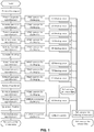
FIG. 1 is a process flow view of the traditional threshing and pneumatic device. -
FIG. 2 is a schematic layout view of the original threshing technology and process arrangement pertaining to the invention. -
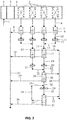
FIG. 3 is a constructed profile view of the binary silos pneumatic separator in the invention. -
FIG. 4 is a constructed profile view of the triple silos pneumatic separator in the invention. - In
FIG. 2 ,1 . Belt conveyer for feeding, 2. Scraper feeder, 3. Silo feeder, 4. Proportional distributor, 5. Primary threshing set, 6. Belt conveyer, 7. Primary pneumatic separation unit (binary silos pneumatic separator), 8. Belt conveyer for tobacco slice, 9. Primary threshing set, 10. Belt conveyer for tobacco leaves with stem, 11. Secondary threshing set, 12. Belt conveyer, 13. Belt conveyer, 14. Belt conveyer, 15. Secondary pneumatic separation unit (triple silos pneumatic separator), 16. Belt conveyer for tobacco stem, 17. Triple silos pneumatic separator, 18. Belt conveyer for tobacco slice, 19. Belt conveyer for tobacco leaves with stem, 20. Tertiary threshing set, 21. Belt conveyer, 22. Belt conveyer, 23. Belt conveyer, 24. Tertiary pneumatic separation unit (a triple silos pneumatic separator), 25. Belt conveyer for tobacco stem, 26. Triple silos pneumatic, 27. Belt conveyer for tobacco slice, 28. Belt conveyer for tobacco leaves with stem, 29. Quaternary threshing set, 30. Belt conveyer, 31. Quaternary pneumatic separation unit (a triple silos pneumatic separator), 32. Belt conveyer for tobacco stem, 33. Belt conveyer for tobacco leaves with stem, 34. Belt conveyer, 35. Belt conveyer, 36. Belt conveyer for tobacco slice, 37. Belt conveyer for collecting tobacco slice, 38. Belt conveyer for collecting tobacco stem. - As shown in
FIG. 3 , 9a- Belt conveyer with high velocity, 9b- Centrifugal ventilator, 9c-Separation silo, 9d-Belt conveyer, 9e-Suction outlet, 9f- Auxiliary air inlet, 9g-Discharge silo, 9h-Vibrating trough, 9i-Discharge port, 9j-Rejection outlet, 9k-Damper plate, 9n-Air inlet. - As shown in
FIG. 4 , 17k1- Damper plate, 17k2- Damper plate, 17j1 - Primary rejection port, 17j2- Secondary rejection port, 17i- Discharge port, 17c1-Primary separation silo, 17c2- Secondary separation silo, 17d- Mesh belt conveyer, 17a-Suction outlet, 17f1- Primary auxiliary air inlet, 17f2- Secondary auxiliary air inlet. - As shown in the
FIG. 1 with the traditional process flow view of the traditional threshing and pneumatic separation procedure, the mixture of the tobacco leaves and stems, which are shredded by the threshing set, is transported by airborne devices to several series pneumatic separators carrying out the air separation. Each pneumatic separator can just sort out some parts of the qualified tobacco slice, and the remaining mixture continues to be transferred in the airborne device. The tobacco stems are discharged at the last pneumatic separator, resulting in heavy loads of pneumatic separator and threshing machine, the high energy consumption of airborne devices, and poor applicability of tobacco stem. - The invention is connected sequentially as the following, scraper feeder → silo feeder → proportional distributor → primary threshing set → belt conveyer → primary pneumatic separation unit (binary silos pneumatic separator) → belt conveyer for tobacco leaves with stem → secondary threshing set → belt conveyer → secondary pneumatic separation unit (triple silos pneumatic separator) → belt conveyer for tobacco leaves with stem → tertiary threshing set → belt conveyer → tertiary pneumatic separation unit (a triple silos pneumatic separator) → belt conveyer for tobacco leaves with stem → quaternary threshing set → belt conveyer → quaternary pneumatic separation unit (a triple silos pneumatic separator).
- The symbol " → " represents two adjoining processes interconnected and immediate adjacent devices mutually communicated.
- The original arrangement for threshing and pneumatic separation with high efficiency and energy conservation as above mentioned, is sequentially connected as the followings: the
scraper feeder 2,silo feeder 3, andproportion distributor 4 are connected in series by belt conveyer, then communicated with the primary threshing set 5, which is comprised of four parallel connected threshing machines. - The discharge ports of each threshing machine are connected through the belt conveyer to the correspondent part of the primary
pneumatic separator unit 7, which is comprised of four binary silospneumatic separators 9. - The discharge ports of each binary silos pneumatic separator in the primary
pneumatic separator unit 7 are communicated through the belt conveyer with the secondary threshing set 11, which is, through the belt conveyer, communicated with the secondarypneumatic separator unit 15 which is comprised of two triple silospneumatic separators 17. - The discharge ports of each triple silos
pneumatic separators 17 in the secondarypneumatic separator unit 15 are connected through the belt conveyer to the tertiary threshing set 20, which is, through the belt conveyer, communicated with the tertiarypneumatic separator unit 24 which is comprised of single triple silospneumatic separator 26. - The discharge port of triple silos
pneumatic separator 26 is connected through the belt conveyer to the quaternary threshing set 29, which is, through the belt conveyer, communicated with the quaternarypneumatic separator unit 31 which adopts a triple silos pneumatic separator. - Each pneumatic separator of the pneumatic separator units at different stage above mentioned is respectively communicated, through the belt conveyer for tobacco stem, thereof for tobacco slice, and thereof for tobacco leaves with stem, with the each threshing machine of the threshing units at different stage above mentioned, each threshing machine of the primary threshing set is respectively communicated, through the correspondent belt conveyer, with each branch of the secondary pneumatic separation unit, the branches of the primary separation unit, as well as the secondary separation unit, are parallel arranged, each branch thereof is consists of one or more tandem pneumatic separator and respectively communicated, through the correspondent belt for tobacco leaves with stem, with one threshing machine of the next stage threshing set.
- As for the secondary and tertiary threshing set, every two threshing machines are yet communicated through the belt conveyer with one branch of individual pneumatic separator of the next stage pneumatic separation unit. The primary pneumatic separation unit, is provided with air pressure type binary silos pneumatic separator, can only sort out qualified tobacco slice, the secondary-, tertiary-, and quaternary pneumatic separation unit, is provided with air pressure type triple silos pneumatic separator, can sort out qualified tobacco slice and tobacco stem.
- Specifically, the velocity of the positive pressure of the air inlet at the bottom of the separation silo in the involved binary silos pneumatic separator, is adjusted by the damper plate located at the air inlet, leads to the position of the air equilibrium surface can being adjusted up and down, making the thrown tobacco mixture from the feeing port separated, the heavier stems fall on the vibrating trough mounted at the bottom of the separation silo and are transported out of the rejection port, the lighter by the effect of the negative pressure are absorbed on the belt conveyor installed on the top of the separator silo, which are transferred into the discharge silo with the operation of the belt conveyor. Since the air pressure inside the discharge silo is the same with the outside air pressure, in its own inertia, the lighter tobacco slices fall in a parabolic path to the discharge port and are discharged, the fine dust and the debris, whose size is less than the mesh aperture dimension, are effected by the negative pressure and infiltrate the mesh belt conveyor and the suction outlet into the dust exhaust removal system.
- Specifically, the involved binary silos pneumatic separator possesses two serial separator silos and one discharge silo, an auxiliary air inlet is installed at the upper side of the intervals of the every two adjacent silos, the position of the air equilibrium surface thereof is regulated differently, the heavier tobacco stems are transported out of the first rejection port at the lower part of the primary separation silo, yet the lighter stems are transported out of the second rejection port at the lower part of the secondary separation silo, the lighter tobacco slices are sent out at the discharge port of the discharge silo, the fine dust and the debris, whose size is less than the mesh aperture dimension, are effected by the negative pressure and infiltrate the mesh belt conveyor and the suction outlet into the dust exhaust removal system.
- As shown in
FIG. 2 , after the secondary conditioning process, the heated and humidified tobacco leaves are transferred by the feeding belt conveyor 1 into the scraper feeder 2, then into the silo feeder 3 so balancing the feeding flow, the proportion distributor 4 evenly distribute the tobacco leaves into the each threshing machine of the threshing set to rip the tobacco slices and stems, the mixture of the tobacco slices and stems coming out of the threshing machine is respectively transported by the belt conveyor 6 into each branch of the primary pneumatic separation unit, the sorted tobacco slices separated by the binary silos pneumatic separator 9 drop on the belt conveyor 8, then are transported onto the slice collection belt conveyor 37, the remaining mixture falls on the belt conveyor for the stem-containing tobacco slice 10 and is transferred again into the secondary threshing set 11, the mixture of the tobacco slices and stems coming out of each threshing machine thereof, is collected by the belt conveyors 12, 13, and 14, transported into each branch of the secondary pneumatic separation unit 15, the sorted tobacco slices separated by the triple silos pneumatic separator 17 drop on the belt conveyor 18, then are transported onto the slice collection belt conveyor 37, the qualified stems fall on the belt conveyor for the stem 16, and is transferred to the stem-collected belt conveyor 38, the remaining mixture falls on the stem-containing belt conveyor 19 and is transported into the tertiary threshing set 20, the mixture of the tobacco slices and stems coming out of the two threshing machines of which, is collected by the belt conveyors 21, 22, and 23, transported into each branch of the tertiary pneumatic separation unit 24, the sorted tobacco slices separated by the triple silos pneumatic separator 26 drop on the belt conveyor 27, then are transported onto the slice collection belt conveyor 37, the qualified stems fall on the belt conveyor for the stem 25, and is transferred to the stem-collected belt conveyor 38, the remaining mixture falls on the stem-containing belt conveyor 28 and is transported into the quaternary threshing set 29, the mixture of the tobacco slices and stems coming out of which, is transported by the belt conveyor 30 to the branch of the quaternary pneumatic separation unit 31, the sorted tobacco slices separated by the triple silos pneumatic separator drop on the belt conveyor 36, then are transported onto the slice collection belt conveyor 37, the qualified stems fall on the belt conveyor for the stem 32, and is transferred to the stem-collected belt conveyor 38, the remaining mixture falls on the stem-containing belt conveyor 33 and is transported through the belt conveyors 33, 34 back onto the belt conveyor 28. - The involved pneumatic separator binary silos cabin pneumatic separator adopts high-speed belt conveyor to feed the materials at the feeding port, the velocity of belt conveyor is between 2-5 m/s, the
air inlet 9n of the separation silo and thesuction outlet 9e are respectively connect to thecentrifugal ventilator 9b with different capacity, theauxiliary air inlet 9f is communicated with theair inlet 9n, high-speed belt conveyor 9a,ventilator 9b, and the motor of the mesh belt conveyor 9d are all controlled by frequency conversion speed regulators. - As shown in
FIG. 3 , for example, the binary silos operates as the following process, the mixture of the tobacco slices and stems is thrown into the separation silo 9c by the high-speed belt conveyer, under the effects of the positive pressure at the bottom of theinlet air 9n and the negative pressure to the top of thesuction outlet 9e, the tobacco slices and stems are separated, the heavier stems containing tobacco leaves fall on the vibrating trough at the lower part of the separation silo, and are sent out at therejection outlet 9j, the lighter tobacco slices are absorbed on the belt conveyer 9d with the effect of the negative pressure, which are transferred to the discharge silo with the driving movement of the mesh belt conveyer 9d, the tobacco slice thereof, under the effects of positive pressure at the auxiliary air inlet 9c and its own inertia, drop in a parabolic path to thedischarge port 9i, the fine dust and debris, whose size is less than dimension of the mesh aperture on the belt conveyer 9d, infiltrate the mesh belt conveyer 9d into the dust exhaust system through thesuction outlet 9e. According to the different input flow of the mixture of the tobacco leaves and stems, the air flow velocity of each binary silos pneumatic separator can be adjusted through regulating thedamper plate 9n, which is located, where theair inlet 9n is, at the bottom of the separator 9c, causing to transforming the pressure equilibrium surface of the positive air pressure in the separation 9c and the negative air pressure at the suction outlet at the top, making the thrown tobacco mixture sorted out with high quality. - The air pressure type triple silos pneumatic separator possesses two serial separation silos 17c1, 17c2, and a
discharge silo 17g, while the heavier tobacco stems are brought out from the first rejection outlet 17j1 mounted at the lower part of the first separation silo 17c1, from the second rejection outlet 17j2 mounted at the lower part of the second separation silo 17c2, the heavier tobacco stems with slice are brought out, the lighter tobacco slices are discharged from the discharge port of the discharge silo. The position adjustment of the positive and negative pressure equilibrium surface of the two separation silos thereof, is accomplished by regulating the damper plates of 17k1 and 17k2. The marked 17f1 located at the communication port between the primary and secondary separation silo, is provided with the air curtain isolating these two silos. - After the above mentioned process flow, by the velocity adjustment of the belt conveyer, and the position adjustment of the pressure equilibrium surface in the separation silos, which are part of each binary silos and triples silos pneumatic separators in the primary, secondary, tertiary and quaternary pneumatic separation units, accomplishes the sorting out of the qualified tobacco slices and stems, achieving the purpose of high efficiency and energy conservation of the original technology and arrangement in accordance with the invention.
- The invention consequentially connects the devices as follows. The
scraper feeder 2,silo feeder 3, andproportion distributor 4 are connected in series by belt conveyer, and then communicated with the primary threshing set 5, which is comprised of four parallel connected threshing machines. - The discharge ports of each threshing machine are connected through the belt conveyer to the correspondent part of the primary
pneumatic separator unit 7, which is comprised of four binary silospneumatic separators 9. - The discharge ports of each binary silos pneumatic separator in the primary
pneumatic separator unit 7 are communicated through the belt conveyer with the secondary threshing set 11, which is, through the belt conveyer, communicated with the secondarypneumatic separator unit 15 which is comprised of two triple silospneumatic separators 17. - The discharge ports of each triple silos
pneumatic separators 17 in the secondarypneumatic separator unit 15 are connected through the belt conveyer to the tertiary threshing set 20, which is, through the belt conveyer, communicated with the tertiarypneumatic separator unit 24 which is comprised of single triple silospneumatic separator 26. - The discharge port of triple silos
pneumatic separator 26 is connected through the belt conveyer to the quaternary threshing set 29, which is, through the belt conveyer, communicated with the quaternarypneumatic separator unit 31 which adopts a triple silos pneumatic separator. - Each pneumatic separator of the pneumatic separator units at different stage above mentioned is respectively communicated, through the belt conveyer for tobacco stem, thereof for tobacco slice, and thereof for tobacco leaves with stem, with the each threshing machine of the threshing units at different stage above mentioned.
- The original technology and arrangement of the invention is concise and clear with the standardized equipment layout, by adopting the belt conveyors, vibrating trough, vibrating screen, and metal belt conveyers with meshes to transport materials, the various devices are organically combined leading to the improvement of the production continuity by the reduction of the possibility of caulking.
- In the invention, while the tobacco slices, stems, and etc. are sorted out, the devices such as the threshing set, the pneumatic separation unit gradually decreased in dimension, by the constructive application of the adsorption characteristics of tobacco to being transported with metal mesh belt conveyor, that ensures the moisture content of tobacco slice, improves the rates of the long and medium size tobacco slice.
Claims (9)
- A method for threshing and pneumatic separation of tobacco leaves by a separation device, the separation device consisting of the following immediate adjacent mutually communicated devices:a scraper feeder (2); a silo feeder (3); a proportional distributor (4); a primary threshing set (5); first belt conveyors (6); a primary pneumatic separation unit (7) comprising a binary silos pneumatic separator (9); belt conveyers (10) for tobacco leaves with stem;a secondary threshing set (11); second belt conveyors (12, 13, 14); a secondary pneumatic separation unit (15) comprising a triple silos pneumatic separator (17); belt conveyers (19) for tobacco leaves with stem;a tertiary threshing set (20); third belt conveyors (21, 22, 23); a tertiary pneumatic separation unit (24) comprising a triple silos pneumatic separator (26); a belt conveyer (28) for tobacco leaves with stem;a quaternary threshing set (29); a fourth belt conveyor (30); anda quaternary pneumatic separation unit (31); the method comprising:
consecutively transferring the tobacco leaves through the scraper feeder (2), the silo feeder (3), the proportional distributor (4), the primary threshing set (5), the first belt conveyors (6), the primary pneumatic separation unit (7), the belt conveyers (10) for tobacco leaves with stem, the secondary threshing set (11), the second belt conveyors (12, 13, 14), the secondary pneumatic separation unit (15), the belt conveyers (19) for tobacco leaves with stem, the tertiary threshing set (20), the third belt conveyors (21, 22, 23), the tertiary pneumatic separation unit (24), the belt conveyer (28) for tobacco leaves with stem, the quaternary threshing set (29), the fourth belt conveyor (30) and the quaternary pneumatic separation unit (31); wherein:
the primary pneumatic separation unit (7) is provided with air pressure type binary silos pneumatic separator, and is adapted only to sort out qualified tobacco slice; the secondary- (15), tertiary- (24), and quaternary- (31) pneumatic separation units are provided with air pressure type triple silos pneumatic separator, and are adapted to sort out qualified tobacco slice and tobacco stem; wherein:the binary silos pneumatic separator (9) comprises a separation silo (9c) and a first discharge silo (9g); a shared upper sidewall of the separation silo (9c) is communicated with the first discharge silo (9g) through a communication port;a first air curtain is disposed in the communication port to isolate the separation silo (9c) and the first discharge silo (9g) from each other;a first discharge port (9i) is disposed at the bottom of the first discharge silo (9g); a first suction outlet (9e) is mounted on the top of the separation silo (9c); a first feeding port is disposed at the lower part of a sidewall of the separation silo (9c); a first mesh belt conveyer (9d) is horizontally arranged in the separation silo (9c) and the first discharge silo (9g); the first feeding port is precisely facing towards one end of the first mesh belt conveyor (9d); a vibration trough (9h) is arranged at the lower part of the separation silo (9c); a first damper plate (9k) is disposed underside the vibration trough (9h); a draft inlet (9n) is located underbelly of the first damper plate (9k) at the bottom of the separation silo (9c); a rejection outlet (9j) is installed at the underside of one end of the vibration trough (9h); the first air curtain comprises an auxiliary draft inlet (9f) disposed in the communication port;a series of air holes are disposed on the topside of the auxiliary draft inlet (9f); the series of air holes are vertically facing the first mesh belt conveyor (9d); the first discharge silo (9g) has a trumpet shape of which the upper part is bigger than the lower;tilt sidewalls of the first discharge silo (9g) are provided with angle regulators; andthe first damper plate (9k) adopts pull chute, which is mounted beneath the vibration trough (9h). - The method of claim 1, characterized in thateach threshing machine of the primary threshing set (5) is communicated, through the correspondent belt conveyor (6), with one branch of the primary pneumatic separation unit (7); the branches of the primary pneumatic separation unit (7), as well as the secondary pneumatic separation unit (15), are parallel arranged;each branch of the primary (7) and secondary (15) pneumatic separation unit consists of one or more tandem pneumatic separators (9, 17), and communicates through the correspondent belt conveyer (10, 19) for tobacco leaves with stem, with one threshing machine of the next stage threshing set (11, 20); andas for the secondary (11) and tertiary (20) threshing set, every two threshing machines are yet communicated through the corresponding belt (12, 13, 14, 21, 22, 23) with one branch of individual pneumatic separator of the next stage pneumatic separation unit (15, 24).
- The method of claim 1, characterized in thatthe triple silos pneumatic separator (17) comprises a second suction outlet (17a), a second mesh belt conveyor (17d), a second feeding port, a primary air inlet, a primary auxiliary draft inlet (17f1), a primary rejection port (17j1), a secondary air inlet, a secondary rejection port (17j2), a second discharge port, a scratch brush, a second discharge silo (17g), a primary separation silo (17c1), a secondary separation silo (17c2), and a secondary auxiliary draft inlet (17f2); the primary separation silo (17c1) is communicated, through a first passage on the shared upper sidewall of the primary (17c1) and secondary (17c2) separation silos, with the secondary separation silo (17c2), which just is communicated, through a second passage on the shared upper sidewall of the secondary separation silo (17c2) and the second discharge silo (17g), with the second discharge silo (17g), forming a structure of communication in series of triple silos;the second mesh belt conveyer (17d) is horizontally disposed on the upside of the second feeding port, and mounted in the triple silos through the first and the second passages, wherein each of the first and the second passages is provided with a second air curtain to isolate the adjacent silos of the triple silos from each other;the second discharge port is disposed at the bottom of the second discharge silo (17g); the second suction outlet (17a) is provided on the top of each of the primary (17c1) and secondary (17c2) separation silos;the second feeding port is disposed at the lower part of a sidewall of the primary separation silo (17c1), which is plumb in the face of the underside of one end of the second mesh belt conveyor (17d); two vibration troughs with meshes are arranged at the lower parts of the primary (17c1) and secondary (17c2) separation silos, respectively;two second damper plates (17k1, 17k2) are disposed each underside one of the two vibration troughs with meshes;the primary and secondary air inlets are located each underbelly of one of the two second damper plates (17k1, 17k2) and against the bottom ports of the primary (17c1) and secondary (17c2) separation silos, respectively;the primary rejection port (17j1) is installed under one end of one of the two vibration troughs with meshes;the secondary rejection port (17j2) is installed under one end of the other of the two vibration troughs with meshes;the second air curtain comprises the primary auxiliary air inlet (17f1) installed in the first passage, or comprises the secondary auxiliary air inlet (17f2) mounted in the second passage, each of the primary (17f1) and secondary (17f2) auxiliary air inlets is provided with a series of vertical air outlets against the second mesh belt conveyor (17d).
- The method of claim 3, characterized in that the second discharge silo (17g) has a trumpet shape of which upper part is bigger than lower part, tilt sidewalls of which are provided with angle regulators, each of the two second damper plates (17k1, 17k2) adopts pull chute, which is mounted beneath one of the two vibration troughs with meshes.
- The method of claim 3, characterized in that by respectively replacing the two second damper plates (17k1, 17k2), the velocity of the positive pressure air flowing into the primary (17c1) and secondary (17c2) separation silos is adjusted with a result of the air profiles of the primary (17c1) and secondary (17c2) separation silos presenting different air pressure and velocity, causing the adjacent silos being in different pressure, the primary separation silo (17c1) is different from the secondary separation silo (17c2), which is different from the second discharge silo (17g).
- The method of claim 3, characterized in that it adopts a perpendicular angle bending structure, so that the pressure-balanced plane in each separation silo takes forms with the pressure on the right being lower than the pressure on the left; and each of the primary (17c1) and secondary (17c2) separation silos has a trumpet shape of which upper part is bigger than lower part, tilt sidewalls of which are provided with angle regulators.
- The method of claim 3, characterized in that the primary (17c1) and secondary (17c2) separation silos of the triple silos pneumatic separator (17) are in the state, which takes positive pressure on the upper side, and negative pressure on the lower side, which are used for realizing the quaternary material separation by the primary (17c1) and secondary (17c2) separation silos thereof, and the pressure equilibrium plane thereof is adjusted; the adjacent primary (17c1) and secondary (17c2) separation silos are isolated from each other by a separator plate, as well as the secondary separation silo (17c2) from the second discharge silo (17g), and are communicated with a material passage.
- The method of claim 3, characterized in that the pressure at the first suction outlet (9e) or the second suction outlet (17a) is 100-2100 Pa lower than the standard atmospheric pressure, the pressure at the vibration trough with meshes is 100-2000 Pa higher than the standard atmospheric pressure, the draft inlet (9e, 17a) connected to the underbelly of the first damper plate (9k) or the primary or secondary air inlet connected to the underbelly of one of the two second damper plates (17k1, 17k2) takes a rectangular bending structure, the airflow direction of the horizontal section of the draft inlet (9e, 17a) is consistent with the transferring direction of the first mesh belt conveyor (17d), the airflow direction of the horizontal section of the primary or secondary air inlet is consistent with the transferring direction of the second mesh belt conveyer, and the pressure in the first (9g) or second (17g) discharge silo is equal to the standard atmospheric pressure, the end of the first mesh belt conveyer (9d) located in the first discharge silo (9g) is provided with a scratch brush, or the end of the second mesh belt conveyer (17d) located in the second discharge silo (17g) is provided with a scratch brush, and the first (9d) or second (17d) mesh belt conveyer is equipped with corrective and tensioning means.
- The method of claim 1, characterized in that:the scraper feeder (2), the silo feeder (3), and the proportion distributor (4) are connected in series by fifth belt conveyers;the primary threshing set (5) is comprised of four parallel connected threshing machines;discharge ports of the four parallel connected threshing machines are connected through the first belt conveyers (6) to the correspondent part of the primary pneumatic separation unit (7); the primary pneumatic separation unit (7) is comprised of four binary silos pneumatic separators (9); discharge ports of the four binary silos pneumatic separators (9) are connected through the belt conveyers (10) for tobacco leaves with stem to the secondary threshing set (11); the secondary threshing set (11) is, through the second belt conveyors (12, 13, 14), communicated with the secondary pneumatic separation unit (15); the secondary pneumatic separation unit (15) is comprised of two triple silos pneumatic separators (17); discharge ports of the two triple silos pneumatic separators (17) are connected through the belt conveyers (19) for tobacco leaves with stem to the tertiary threshing set (20); the tertiary threshing set (20) is, through the third belt conveyors (21, 22, 23), communicated with the tertiary pneumatic separation unit (24); the tertiary pneumatic separation unit (24) is comprised of a single triple silos pneumatic separator (26); discharge port of the single triple silos pneumatic separator (26) is connected through the belt conveyer (28) for tobacco leaves with stem to the quaternary threshing set (29); the quaternary threshing set (29) is, through the fourth belt conveyor (30), communicated with the quaternary pneumatic separation unit (31); andthe quaternary pneumatic separation unit (31) adopts a single triple silos pneumatic separator.
Applications Claiming Priority (2)
| Application Number | Priority Date | Filing Date | Title |
|---|---|---|---|
| CN201310230300.4A CN103263075B (en) | 2013-06-11 | 2013-06-11 | High efficiency energy saving leaf beating wind separating new technology and equipment |
| PCT/CN2014/079652 WO2014198219A1 (en) | 2013-06-11 | 2014-06-11 | New highly-efficient energy-saving threshing air separation process and device |
Publications (3)
| Publication Number | Publication Date |
|---|---|
| EP3011844A1 EP3011844A1 (en) | 2016-04-27 |
| EP3011844A4 EP3011844A4 (en) | 2016-10-05 |
| EP3011844B1 true EP3011844B1 (en) | 2018-05-09 |
Family
ID=49006777
Family Applications (1)
| Application Number | Title | Priority Date | Filing Date |
|---|---|---|---|
| EP14811523.1A Active EP3011844B1 (en) | 2013-06-11 | 2014-06-11 | Highly-efficient energy-saving threshing air separation process |
Country Status (6)
| Country | Link |
|---|---|
| US (1) | US9961934B2 (en) |
| EP (1) | EP3011844B1 (en) |
| JP (1) | JP6167231B2 (en) |
| CN (1) | CN103263075B (en) |
| CA (1) | CA2914981C (en) |
| WO (1) | WO2014198219A1 (en) |
Families Citing this family (27)
| Publication number | Priority date | Publication date | Assignee | Title |
|---|---|---|---|---|
| CN103263075B (en) * | 2013-06-11 | 2015-08-12 | 红塔烟草(集团)有限责任公司 | High efficiency energy saving leaf beating wind separating new technology and equipment |
| CN105642551A (en) * | 2014-12-02 | 2016-06-08 | 北京长征高科技公司 | Fine air separation system for threshed tobacco leaves |
| CN105725256B (en) * | 2016-02-05 | 2017-11-03 | 江苏恒森烟草机械有限公司 | A kind of device and method of utilization circulated air material casting |
| CN106174682B (en) * | 2016-08-24 | 2017-07-04 | 红塔烟草(集团)有限责任公司 | 18 scores of wind dispensing units and method for processing tobacco leaf are made with five |
| CN106615272B (en) * | 2016-12-05 | 2021-10-22 | 浙江理工大学 | Multi-stage differential speed tea fresh leaf sorting single-row conveyor and its single-row conveying method |
| CN106723296B (en) * | 2016-12-16 | 2018-11-20 | 广东中烟工业有限责任公司 | The method that half Turkish tobaccos tobacco leaf of Turkey goes stalk processing and redrying processing |
| CN107626592A (en) * | 2017-09-30 | 2018-01-26 | 云南昆船烟草设备有限公司 | A kind of multipass sort method and device of bulk mixed material |
| CN108889623B (en) * | 2018-07-11 | 2024-02-13 | 阜阳丰达机电设备有限公司 | Cut tobacco scattering air extension machine |
| CN108851185A (en) * | 2018-07-30 | 2018-11-23 | 重庆烟叶复烤有限公司万州复烤厂 | A kind of accurate wind dispensing method |
| CN109938390A (en) * | 2019-05-05 | 2019-06-28 | 云南中烟工业有限责任公司 | It is a kind of to improve the feeding method and device for beating leaf process operational efficiency |
| CN110665820B (en) * | 2019-10-24 | 2024-07-09 | 国营云南机器三厂烟机配件分厂 | Tobacco leaf fragment sorting, impurity removing and recycling equipment and recycling method |
| CN110787999A (en) * | 2019-11-04 | 2020-02-14 | 中冶长天国际工程有限责任公司 | Wind separation and removal device and control method of fine particle dust in lime kiln, lime kiln |
| CN110788000A (en) * | 2019-11-04 | 2020-02-14 | 中冶长天国际工程有限责任公司 | Device and control method for air separation and removal of fine particle dust in lime kiln, and lime kiln |
| CN111804591B (en) * | 2020-06-19 | 2025-04-29 | 重庆中烟工业有限责任公司 | A tobacco shaping device |
| CN112042997B (en) * | 2020-08-18 | 2022-05-03 | 红塔烟草(集团)有限责任公司 | Energy-saving efficient threshing and air separating system |
| CN112089089B (en) * | 2020-10-10 | 2023-09-05 | 云南中烟工业有限责任公司 | A device and method for removing light flakes from shredded stems using deflectors |
| CN114343224B (en) * | 2020-10-13 | 2025-08-12 | 北京长征高科技有限公司 | Classified threshing device and method |
| CN112998307B (en) * | 2021-01-27 | 2022-12-06 | 上海景亚电气自动化科技有限公司 | Tobacco threshing and stem removing separation device |
| CN112808587A (en) * | 2021-02-09 | 2021-05-18 | 塔里木大学 | High-efficient walnut shell benevolence separation machinery of doublestage |
| CN115956702B (en) * | 2021-05-28 | 2024-08-23 | 芜湖启迪睿视信息技术有限公司 | Tobacco leaf separation equipment |
| CN114918132B (en) * | 2022-06-08 | 2024-02-13 | 红云红河烟草(集团)有限责任公司 | An online sorting and recycling process for leaf shreds cooling process |
| CN115041409B (en) * | 2022-06-10 | 2023-11-03 | 安徽农业大学 | Double-air-duct tea winnowing machine |
| CN115445927B (en) * | 2022-10-15 | 2023-10-27 | 中茶紫阳茶叶有限公司 | Screening machine capable of automatically extracting high-quality tea leaves |
| CN115739634B (en) * | 2022-11-25 | 2025-07-25 | 广西中烟工业有限责任公司 | Cut tobacco and stem sorting and vibrating trough device of cigarette making machine |
| CN116762983A (en) * | 2023-06-19 | 2023-09-19 | 红云红河烟草(集团)有限责任公司 | Temperature and humidity control method and system for threshing wind splitting wind field |
| CN117139166A (en) * | 2023-08-31 | 2023-12-01 | 广西中烟工业有限责任公司 | Tobacco shred secondary flexible winnowing system and method suitable for airflow drying |
| CN118216699B (en) * | 2024-04-26 | 2026-04-03 | 安徽中烟工业有限责任公司 | A machine vision-based flexible intelligent air separation system for tobacco shreds |
Family Cites Families (41)
| Publication number | Priority date | Publication date | Assignee | Title |
|---|---|---|---|---|
| US1593688A (en) * | 1925-03-13 | 1926-07-27 | American Tobacco Co | Method and apparatus for stemming tobacco |
| US1879016A (en) * | 1929-12-04 | 1932-09-27 | Lorillard Co P | Threshing machine for tobacco |
| US3043315A (en) * | 1958-03-19 | 1962-07-10 | Mignot & De Block Nv | Tobacco threshing-winnowing machines |
| GB854230A (en) * | 1958-08-27 | 1960-11-16 | Vokes Ltd | Improvements in tobacco processing machinery |
| US3128775A (en) * | 1961-01-18 | 1964-04-14 | American Mach & Foundry | Method for processing tobacco for use in the manufacture of cigarettes |
| DE1532092B2 (en) * | 1965-11-03 | 1976-04-22 | DEVICE FOR STRIPPING TOBACCO SHEETS AND SIGHTING THE GOODS RECEIVED | |
| US4162768A (en) * | 1977-11-08 | 1979-07-31 | Blaine Froats | Apparatus for separating paper fibres from portions of polyethylene film material |
| NL7801797A (en) * | 1978-02-17 | 1979-08-21 | Arenco Pmb Bv | DEVICE FOR SPREADING ONE HALF TOBACCO LEAF PART ONCE. |
| US4237909A (en) * | 1978-04-24 | 1980-12-09 | Brown & Williamson Tobacco Corp. | Method and apparatus for tobacco leaf destemming |
| US4475562A (en) * | 1981-10-16 | 1984-10-09 | Philip Morris Incorporated | Method and apparatus for separating tobacco mixture into lighter and heavier fractions |
| US4449540A (en) * | 1982-02-17 | 1984-05-22 | Parker Tobacco Company | Separation of lamina from stems in baled tobacco |
| US4566470A (en) * | 1982-10-28 | 1986-01-28 | Rothmans Of Pall Mall Canada Limited | Tobacco leaf processing |
| JPS6071361U (en) * | 1983-10-20 | 1985-05-20 | 日本たばこ産業株式会社 | electrostatic separation device |
| US4696312A (en) * | 1986-03-17 | 1987-09-29 | Philip Morris Incorporated | Method and apparatus for producing cigarette filler |
| US4934385A (en) * | 1987-07-11 | 1990-06-19 | Korber Ag | Method of and apparatus for treating uncured tobacco |
| US5099863A (en) * | 1987-08-24 | 1992-03-31 | Universal Leaf Tobacco Co., Inc. | Apparatus for separating threshed leaf tobacco |
| GB8825731D0 (en) * | 1988-11-03 | 1988-12-07 | Gbe International Plc | Apparatus for separation of particulate material(eg tobacco) |
| DE3905123A1 (en) * | 1989-02-20 | 1990-08-23 | Kloeckner Humboldt Deutz Ag | Sifter for sifting granular material and milling system with the activation of such a sifter |
| IT1235753B (en) * | 1989-05-05 | 1992-09-24 | Sev Srl | DEVICE FOR BEATING PARTICULARLY TOBACCO LEAVES |
| US5016823A (en) * | 1989-05-12 | 1991-05-21 | Canon Kabushiki Kaisha | Air current classifier, process for preparing toner, and apparatus for preparing toner |
| US5024334A (en) * | 1989-06-09 | 1991-06-18 | Iowa State University Research Foundation, Inc. | Method and means for gravity table automation |
| US5205415A (en) * | 1991-07-10 | 1993-04-27 | The Standard Commercial Tobacco Co., Inc. | Modular classifier |
| US5394893A (en) * | 1993-10-22 | 1995-03-07 | Universal Leaf Tobacco Co., Ltd. | Modular style multi-separator |
| US5538017A (en) * | 1994-09-28 | 1996-07-23 | Monk-Austin International, Inc. | Tobacco leaf separator |
| EP0848914A1 (en) * | 1996-12-17 | 1998-06-24 | Imperial Tobacco Limited | Apparatus and process for threshing tobacco |
| CN1240334A (en) * | 1996-12-17 | 2000-01-05 | 帝国烟草有限公司 | Method and apparatus for precessing tobacco |
| EP0853893A1 (en) * | 1996-12-17 | 1998-07-22 | Imperial Tobacco Limited | Method and apparatus for processing tobacco |
| US6435191B1 (en) * | 1999-02-26 | 2002-08-20 | Dimon Inc. | Tobacco separator |
| CN2595185Y (en) * | 2003-01-28 | 2003-12-31 | 秦皇岛烟草机械有限责任公司 | Tobacco leaf threshing device |
| ITMI20041371A1 (en) * | 2004-07-09 | 2004-10-09 | Magaldi Power Spa | INTEGRATED HEAVY ASH EXTRACTION SYSTEM TRANSFORMATION OF THEMSELVES INTO LIGHT ASH AND REDUCTION OF INCOMBUSTS |
| CN2927717Y (en) * | 2006-07-20 | 2007-08-01 | 北京长征高科技公司 | High efficiency energy saving leaf beating wind separating unit |
| CN201260375Y (en) * | 2008-09-12 | 2009-06-24 | 秦皇岛烟草机械有限责任公司 | Separated flow type pneumatic separating tobacco leaf-stripping machine |
| CN201752231U (en) * | 2010-01-27 | 2011-03-02 | 北京长征高科技公司 | Combined flexible tobacco leaf threshing unit |
| CN101999752B (en) * | 2010-10-22 | 2013-09-04 | 红塔烟草(集团)有限责任公司 | Method for slitting, striking and redrying tobacco |
| EP2489283A1 (en) * | 2011-02-18 | 2012-08-22 | Philip Morris Products S.A. | Method of processing tobacco leaves |
| CN202566251U (en) * | 2012-03-14 | 2012-12-05 | 秦皇岛烟草机械有限责任公司 | Threshed tobacco leaf collecting and processing system with sand sieving function |
| CN102626257A (en) * | 2012-03-23 | 2012-08-08 | 秦皇岛烟草机械有限责任公司 | High-speed air separator |
| CN102813277B (en) * | 2012-09-18 | 2014-04-09 | 中国烟草总公司郑州烟草研究院 | Tobacco leaf threshing and destemming technical method and special equipment thereof |
| CN103263075B (en) * | 2013-06-11 | 2015-08-12 | 红塔烟草(集团)有限责任公司 | High efficiency energy saving leaf beating wind separating new technology and equipment |
| CN103263074B (en) * | 2013-06-11 | 2016-01-06 | 红塔烟草(集团)有限责任公司 | A kind of high efficiency energy saving leaf beating wind separating Processes and apparatus |
| CN203492771U (en) * | 2013-06-11 | 2014-03-26 | 红塔烟草(集团)有限责任公司 | Novel efficient and energy-saving threshing and air separation system |
-
2013
- 2013-06-11 CN CN201310230300.4A patent/CN103263075B/en active Active
-
2014
- 2014-06-11 WO PCT/CN2014/079652 patent/WO2014198219A1/en not_active Ceased
- 2014-06-11 CA CA2914981A patent/CA2914981C/en active Active
- 2014-06-11 EP EP14811523.1A patent/EP3011844B1/en active Active
- 2014-06-11 JP JP2016518828A patent/JP6167231B2/en active Active
-
2015
- 2015-12-10 US US14/965,886 patent/US9961934B2/en active Active
Non-Patent Citations (1)
| Title |
|---|
| None * |
Also Published As
| Publication number | Publication date |
|---|---|
| CN103263075B (en) | 2015-08-12 |
| US9961934B2 (en) | 2018-05-08 |
| CA2914981C (en) | 2017-12-05 |
| EP3011844A1 (en) | 2016-04-27 |
| WO2014198219A1 (en) | 2014-12-18 |
| EP3011844A4 (en) | 2016-10-05 |
| US20160095346A1 (en) | 2016-04-07 |
| CA2914981A1 (en) | 2014-12-18 |
| CN103263075A (en) | 2013-08-28 |
| JP6167231B2 (en) | 2017-07-19 |
| JP2016520331A (en) | 2016-07-14 |
Similar Documents
| Publication | Publication Date | Title |
|---|---|---|
| CA2914981C (en) | New highly-efficient energy-saving threshing air separation process and device | |
| US9764362B2 (en) | Air-pressure-type dual-bin air-powered separator | |
| JP2016520331A5 (en) | ||
| CN103263074B (en) | A kind of high efficiency energy saving leaf beating wind separating Processes and apparatus | |
| CN102319674B (en) | Equipment and method for solid garbage classification | |
| CN111495560B (en) | A static double-classifying powder selector and semi-final pre-grinding system | |
| CN106690396B (en) | Air separation process and device for improving air separation efficiency and reducing material breakage rate | |
| CN106937756A (en) | A kind of high-efficiency vertical wind subset and its technique for applying | |
| CN103271431B (en) | High efficiency energy saving leaf beating wind separating technique | |
| CN207252766U (en) | A kind of combined type wind divides device | |
| CN103551313B (en) | Double duct system Winnowing type seed purifier | |
| CN103271432A (en) | Air separator capable of separating tobacco stems from tobacco shreds in multi-level manner | |
| CN203492771U (en) | Novel efficient and energy-saving threshing and air separation system | |
| CN203692514U (en) | High efficient energy-saving tobacco-cutting wind-separation equipment | |
| CN203492772U (en) | Efficient and energy-saving threshing and air separation equipment | |
| RU2195805C1 (en) | Grain cleaning unit | |
| CN202059980U (en) | Tobacco leaf threshing shunting winnowing system | |
| CN220879581U (en) | Winnowing system | |
| CN212306766U (en) | Tobacco multi-stage winnowing system | |
| CN111215333B (en) | A symmetrical structure compound cleaning machine | |
| CN208728013U (en) | A kind of grain bran separation device for rice processing | |
| CN106000882A (en) | Multi-channel multi-layer vibration cleaning machine | |
| CA2913188C (en) | Air-pressure-type dual-bin air-powered separator | |
| CN205762314U (en) | Dual pathways independent regulation winnower | |
| CN211989697U (en) | Symmetrical structure compound cleaning and sorting machine |
Legal Events
| Date | Code | Title | Description |
|---|---|---|---|
| PUAI | Public reference made under article 153(3) epc to a published international application that has entered the european phase |
Free format text: ORIGINAL CODE: 0009012 |
|
| 17P | Request for examination filed |
Effective date: 20160105 |
|
| AK | Designated contracting states |
Kind code of ref document: A1 Designated state(s): AL AT BE BG CH CY CZ DE DK EE ES FI FR GB GR HR HU IE IS IT LI LT LU LV MC MK MT NL NO PL PT RO RS SE SI SK SM TR |
|
| AX | Request for extension of the european patent |
Extension state: BA ME |
|
| DAX | Request for extension of the european patent (deleted) | ||
| A4 | Supplementary search report drawn up and despatched |
Effective date: 20160902 |
|
| RIC1 | Information provided on ipc code assigned before grant |
Ipc: B07B 9/02 20060101ALI20160829BHEP Ipc: B07B 4/08 20060101ALI20160829BHEP Ipc: A24B 5/06 20060101AFI20160829BHEP Ipc: B07B 11/06 20060101ALI20160829BHEP |
|
| 17Q | First examination report despatched |
Effective date: 20170113 |
|
| REG | Reference to a national code |
Ref country code: DE Ref legal event code: R079 Ref document number: 602014025365 Country of ref document: DE Free format text: PREVIOUS MAIN CLASS: A24B0005060000 Ipc: B07B0004080000 |
|
| GRAP | Despatch of communication of intention to grant a patent |
Free format text: ORIGINAL CODE: EPIDOSNIGR1 |
|
| RIC1 | Information provided on ipc code assigned before grant |
Ipc: A24B 5/12 20060101ALI20171107BHEP Ipc: B07B 4/08 20060101AFI20171107BHEP Ipc: B07B 11/06 20060101ALI20171107BHEP Ipc: A24B 5/06 20060101ALI20171107BHEP Ipc: B07B 9/02 20060101ALI20171107BHEP |
|
| INTG | Intention to grant announced |
Effective date: 20171214 |
|
| GRAS | Grant fee paid |
Free format text: ORIGINAL CODE: EPIDOSNIGR3 |
|
| GRAA | (expected) grant |
Free format text: ORIGINAL CODE: 0009210 |
|
| AK | Designated contracting states |
Kind code of ref document: B1 Designated state(s): AL AT BE BG CH CY CZ DE DK EE ES FI FR GB GR HR HU IE IS IT LI LT LU LV MC MK MT NL NO PL PT RO RS SE SI SK SM TR |
|
| REG | Reference to a national code |
Ref country code: GB Ref legal event code: FG4D |
|
| REG | Reference to a national code |
Ref country code: CH Ref legal event code: EP Ref country code: AT Ref legal event code: REF Ref document number: 997103 Country of ref document: AT Kind code of ref document: T Effective date: 20180515 |
|
| REG | Reference to a national code |
Ref country code: IE Ref legal event code: FG4D |
|
| REG | Reference to a national code |
Ref country code: DE Ref legal event code: R096 Ref document number: 602014025365 Country of ref document: DE |
|
| REG | Reference to a national code |
Ref country code: FR Ref legal event code: PLFP Year of fee payment: 5 |
|
| REG | Reference to a national code |
Ref country code: NL Ref legal event code: MP Effective date: 20180509 |
|
| REG | Reference to a national code |
Ref country code: LT Ref legal event code: MG4D |
|
| REG | Reference to a national code |
Ref country code: FR Ref legal event code: PLFP Year of fee payment: 6 |
|
| PG25 | Lapsed in a contracting state [announced via postgrant information from national office to epo] |
Ref country code: ES Free format text: LAPSE BECAUSE OF FAILURE TO SUBMIT A TRANSLATION OF THE DESCRIPTION OR TO PAY THE FEE WITHIN THE PRESCRIBED TIME-LIMIT Effective date: 20180509 Ref country code: SE Free format text: LAPSE BECAUSE OF FAILURE TO SUBMIT A TRANSLATION OF THE DESCRIPTION OR TO PAY THE FEE WITHIN THE PRESCRIBED TIME-LIMIT Effective date: 20180509 Ref country code: NO Free format text: LAPSE BECAUSE OF FAILURE TO SUBMIT A TRANSLATION OF THE DESCRIPTION OR TO PAY THE FEE WITHIN THE PRESCRIBED TIME-LIMIT Effective date: 20180809 Ref country code: FI Free format text: LAPSE BECAUSE OF FAILURE TO SUBMIT A TRANSLATION OF THE DESCRIPTION OR TO PAY THE FEE WITHIN THE PRESCRIBED TIME-LIMIT Effective date: 20180509 Ref country code: BG Free format text: LAPSE BECAUSE OF FAILURE TO SUBMIT A TRANSLATION OF THE DESCRIPTION OR TO PAY THE FEE WITHIN THE PRESCRIBED TIME-LIMIT Effective date: 20180809 Ref country code: LT Free format text: LAPSE BECAUSE OF FAILURE TO SUBMIT A TRANSLATION OF THE DESCRIPTION OR TO PAY THE FEE WITHIN THE PRESCRIBED TIME-LIMIT Effective date: 20180509 |
|
| PG25 | Lapsed in a contracting state [announced via postgrant information from national office to epo] |
Ref country code: NL Free format text: LAPSE BECAUSE OF FAILURE TO SUBMIT A TRANSLATION OF THE DESCRIPTION OR TO PAY THE FEE WITHIN THE PRESCRIBED TIME-LIMIT Effective date: 20180509 Ref country code: LV Free format text: LAPSE BECAUSE OF FAILURE TO SUBMIT A TRANSLATION OF THE DESCRIPTION OR TO PAY THE FEE WITHIN THE PRESCRIBED TIME-LIMIT Effective date: 20180509 Ref country code: HR Free format text: LAPSE BECAUSE OF FAILURE TO SUBMIT A TRANSLATION OF THE DESCRIPTION OR TO PAY THE FEE WITHIN THE PRESCRIBED TIME-LIMIT Effective date: 20180509 Ref country code: GR Free format text: LAPSE BECAUSE OF FAILURE TO SUBMIT A TRANSLATION OF THE DESCRIPTION OR TO PAY THE FEE WITHIN THE PRESCRIBED TIME-LIMIT Effective date: 20180810 Ref country code: RS Free format text: LAPSE BECAUSE OF FAILURE TO SUBMIT A TRANSLATION OF THE DESCRIPTION OR TO PAY THE FEE WITHIN THE PRESCRIBED TIME-LIMIT Effective date: 20180509 |
|
| REG | Reference to a national code |
Ref country code: AT Ref legal event code: MK05 Ref document number: 997103 Country of ref document: AT Kind code of ref document: T Effective date: 20180509 |
|
| PG25 | Lapsed in a contracting state [announced via postgrant information from national office to epo] |
Ref country code: CZ Free format text: LAPSE BECAUSE OF FAILURE TO SUBMIT A TRANSLATION OF THE DESCRIPTION OR TO PAY THE FEE WITHIN THE PRESCRIBED TIME-LIMIT Effective date: 20180509 Ref country code: RO Free format text: LAPSE BECAUSE OF FAILURE TO SUBMIT A TRANSLATION OF THE DESCRIPTION OR TO PAY THE FEE WITHIN THE PRESCRIBED TIME-LIMIT Effective date: 20180509 Ref country code: EE Free format text: LAPSE BECAUSE OF FAILURE TO SUBMIT A TRANSLATION OF THE DESCRIPTION OR TO PAY THE FEE WITHIN THE PRESCRIBED TIME-LIMIT Effective date: 20180509 Ref country code: AT Free format text: LAPSE BECAUSE OF FAILURE TO SUBMIT A TRANSLATION OF THE DESCRIPTION OR TO PAY THE FEE WITHIN THE PRESCRIBED TIME-LIMIT Effective date: 20180509 Ref country code: DK Free format text: LAPSE BECAUSE OF FAILURE TO SUBMIT A TRANSLATION OF THE DESCRIPTION OR TO PAY THE FEE WITHIN THE PRESCRIBED TIME-LIMIT Effective date: 20180509 Ref country code: PL Free format text: LAPSE BECAUSE OF FAILURE TO SUBMIT A TRANSLATION OF THE DESCRIPTION OR TO PAY THE FEE WITHIN THE PRESCRIBED TIME-LIMIT Effective date: 20180509 Ref country code: SK Free format text: LAPSE BECAUSE OF FAILURE TO SUBMIT A TRANSLATION OF THE DESCRIPTION OR TO PAY THE FEE WITHIN THE PRESCRIBED TIME-LIMIT Effective date: 20180509 |
|
| REG | Reference to a national code |
Ref country code: CH Ref legal event code: PL |
|
| REG | Reference to a national code |
Ref country code: DE Ref legal event code: R097 Ref document number: 602014025365 Country of ref document: DE |
|
| PG25 | Lapsed in a contracting state [announced via postgrant information from national office to epo] |
Ref country code: IT Free format text: LAPSE BECAUSE OF FAILURE TO SUBMIT A TRANSLATION OF THE DESCRIPTION OR TO PAY THE FEE WITHIN THE PRESCRIBED TIME-LIMIT Effective date: 20180509 Ref country code: SM Free format text: LAPSE BECAUSE OF FAILURE TO SUBMIT A TRANSLATION OF THE DESCRIPTION OR TO PAY THE FEE WITHIN THE PRESCRIBED TIME-LIMIT Effective date: 20180509 |
|
| REG | Reference to a national code |
Ref country code: BE Ref legal event code: MM Effective date: 20180630 |
|
| PLBE | No opposition filed within time limit |
Free format text: ORIGINAL CODE: 0009261 |
|
| STAA | Information on the status of an ep patent application or granted ep patent |
Free format text: STATUS: NO OPPOSITION FILED WITHIN TIME LIMIT |
|
| REG | Reference to a national code |
Ref country code: IE Ref legal event code: MM4A |
|
| PG25 | Lapsed in a contracting state [announced via postgrant information from national office to epo] |
Ref country code: MC Free format text: LAPSE BECAUSE OF FAILURE TO SUBMIT A TRANSLATION OF THE DESCRIPTION OR TO PAY THE FEE WITHIN THE PRESCRIBED TIME-LIMIT Effective date: 20180509 Ref country code: LU Free format text: LAPSE BECAUSE OF NON-PAYMENT OF DUE FEES Effective date: 20180611 |
|
| 26N | No opposition filed |
Effective date: 20190212 |
|
| PG25 | Lapsed in a contracting state [announced via postgrant information from national office to epo] |
Ref country code: LI Free format text: LAPSE BECAUSE OF NON-PAYMENT OF DUE FEES Effective date: 20180630 Ref country code: IE Free format text: LAPSE BECAUSE OF NON-PAYMENT OF DUE FEES Effective date: 20180611 Ref country code: CH Free format text: LAPSE BECAUSE OF NON-PAYMENT OF DUE FEES Effective date: 20180630 |
|
| PG25 | Lapsed in a contracting state [announced via postgrant information from national office to epo] |
Ref country code: SI Free format text: LAPSE BECAUSE OF FAILURE TO SUBMIT A TRANSLATION OF THE DESCRIPTION OR TO PAY THE FEE WITHIN THE PRESCRIBED TIME-LIMIT Effective date: 20180509 Ref country code: BE Free format text: LAPSE BECAUSE OF NON-PAYMENT OF DUE FEES Effective date: 20180630 |
|
| PG25 | Lapsed in a contracting state [announced via postgrant information from national office to epo] |
Ref country code: AL Free format text: LAPSE BECAUSE OF FAILURE TO SUBMIT A TRANSLATION OF THE DESCRIPTION OR TO PAY THE FEE WITHIN THE PRESCRIBED TIME-LIMIT Effective date: 20180509 |
|
| PG25 | Lapsed in a contracting state [announced via postgrant information from national office to epo] |
Ref country code: MT Free format text: LAPSE BECAUSE OF NON-PAYMENT OF DUE FEES Effective date: 20180611 |
|
| PG25 | Lapsed in a contracting state [announced via postgrant information from national office to epo] |
Ref country code: TR Free format text: LAPSE BECAUSE OF FAILURE TO SUBMIT A TRANSLATION OF THE DESCRIPTION OR TO PAY THE FEE WITHIN THE PRESCRIBED TIME-LIMIT Effective date: 20180509 |
|
| PG25 | Lapsed in a contracting state [announced via postgrant information from national office to epo] |
Ref country code: PT Free format text: LAPSE BECAUSE OF FAILURE TO SUBMIT A TRANSLATION OF THE DESCRIPTION OR TO PAY THE FEE WITHIN THE PRESCRIBED TIME-LIMIT Effective date: 20180509 |
|
| PG25 | Lapsed in a contracting state [announced via postgrant information from national office to epo] |
Ref country code: CY Free format text: LAPSE BECAUSE OF FAILURE TO SUBMIT A TRANSLATION OF THE DESCRIPTION OR TO PAY THE FEE WITHIN THE PRESCRIBED TIME-LIMIT Effective date: 20180509 Ref country code: HU Free format text: LAPSE BECAUSE OF FAILURE TO SUBMIT A TRANSLATION OF THE DESCRIPTION OR TO PAY THE FEE WITHIN THE PRESCRIBED TIME-LIMIT; INVALID AB INITIO Effective date: 20140611 Ref country code: MK Free format text: LAPSE BECAUSE OF NON-PAYMENT OF DUE FEES Effective date: 20180509 |
|
| PG25 | Lapsed in a contracting state [announced via postgrant information from national office to epo] |
Ref country code: IS Free format text: LAPSE BECAUSE OF FAILURE TO SUBMIT A TRANSLATION OF THE DESCRIPTION OR TO PAY THE FEE WITHIN THE PRESCRIBED TIME-LIMIT Effective date: 20180909 |
|
| PGFP | Annual fee paid to national office [announced via postgrant information from national office to epo] |
Ref country code: GB Payment date: 20260623 Year of fee payment: 13 |
|
| PGFP | Annual fee paid to national office [announced via postgrant information from national office to epo] |
Ref country code: DE Payment date: 20260623 Year of fee payment: 13 |
|
| PGFP | Annual fee paid to national office [announced via postgrant information from national office to epo] |
Ref country code: FR Payment date: 20260623 Year of fee payment: 13 |