EP3011244B1 - Feed flow conditioner for particulate feed materials - Google Patents
Feed flow conditioner for particulate feed materials Download PDFInfo
- Publication number
- EP3011244B1 EP3011244B1 EP14813725.0A EP14813725A EP3011244B1 EP 3011244 B1 EP3011244 B1 EP 3011244B1 EP 14813725 A EP14813725 A EP 14813725A EP 3011244 B1 EP3011244 B1 EP 3011244B1
- Authority
- EP
- European Patent Office
- Prior art keywords
- feed
- interior chamber
- outlet opening
- charging device
- holding vessel
- Prior art date
- Legal status (The legal status is an assumption and is not a legal conclusion. Google has not performed a legal analysis and makes no representation as to the accuracy of the status listed.)
- Active
Links
Images



Classifications
-
- F—MECHANICAL ENGINEERING; LIGHTING; HEATING; WEAPONS; BLASTING
- F27—FURNACES; KILNS; OVENS; RETORTS
- F27B—FURNACES, KILNS, OVENS OR RETORTS IN GENERAL; OPEN SINTERING OR LIKE APPARATUS
- F27B15/00—Fluidised-bed furnaces; Other furnaces using or treating finely-divided materials in dispersion
-
- F—MECHANICAL ENGINEERING; LIGHTING; HEATING; WEAPONS; BLASTING
- F27—FURNACES; KILNS; OVENS; RETORTS
- F27D—DETAILS OR ACCESSORIES OF FURNACES, KILNS, OVENS OR RETORTS, IN SO FAR AS THEY ARE OF KINDS OCCURRING IN MORE THAN ONE KIND OF FURNACE
- F27D3/00—Charging; Discharging; Manipulation of charge
- F27D3/0033—Charging; Discharging; Manipulation of charge charging of particulate material
-
- F—MECHANICAL ENGINEERING; LIGHTING; HEATING; WEAPONS; BLASTING
- F23—COMBUSTION APPARATUS; COMBUSTION PROCESSES
- F23K—FEEDING FUEL TO COMBUSTION APPARATUS
- F23K3/00—Feeding or distributing of lump or pulverulent fuel to combustion apparatus
-
- F—MECHANICAL ENGINEERING; LIGHTING; HEATING; WEAPONS; BLASTING
- F27—FURNACES; KILNS; OVENS; RETORTS
- F27D—DETAILS OR ACCESSORIES OF FURNACES, KILNS, OVENS OR RETORTS, IN SO FAR AS THEY ARE OF KINDS OCCURRING IN MORE THAN ONE KIND OF FURNACE
- F27D19/00—Arrangements of controlling devices
-
- F—MECHANICAL ENGINEERING; LIGHTING; HEATING; WEAPONS; BLASTING
- F27—FURNACES; KILNS; OVENS; RETORTS
- F27D—DETAILS OR ACCESSORIES OF FURNACES, KILNS, OVENS OR RETORTS, IN SO FAR AS THEY ARE OF KINDS OCCURRING IN MORE THAN ONE KIND OF FURNACE
- F27D3/00—Charging; Discharging; Manipulation of charge
- F27D3/18—Charging particulate material using a fluid carrier
-
- F—MECHANICAL ENGINEERING; LIGHTING; HEATING; WEAPONS; BLASTING
- F27—FURNACES; KILNS; OVENS; RETORTS
- F27D—DETAILS OR ACCESSORIES OF FURNACES, KILNS, OVENS OR RETORTS, IN SO FAR AS THEY ARE OF KINDS OCCURRING IN MORE THAN ONE KIND OF FURNACE
- F27D99/00—Subject matter not provided for in other groups of this subclass
- F27D99/0001—Heating elements or systems
- F27D99/0033—Heating elements or systems using burners
-
- F—MECHANICAL ENGINEERING; LIGHTING; HEATING; WEAPONS; BLASTING
- F27—FURNACES; KILNS; OVENS; RETORTS
- F27D—DETAILS OR ACCESSORIES OF FURNACES, KILNS, OVENS OR RETORTS, IN SO FAR AS THEY ARE OF KINDS OCCURRING IN MORE THAN ONE KIND OF FURNACE
- F27D3/00—Charging; Discharging; Manipulation of charge
- F27D2003/0001—Positioning the charge
- F27D2003/0006—Particulate materials
-
- F—MECHANICAL ENGINEERING; LIGHTING; HEATING; WEAPONS; BLASTING
- F27—FURNACES; KILNS; OVENS; RETORTS
- F27D—DETAILS OR ACCESSORIES OF FURNACES, KILNS, OVENS OR RETORTS, IN SO FAR AS THEY ARE OF KINDS OCCURRING IN MORE THAN ONE KIND OF FURNACE
- F27D3/00—Charging; Discharging; Manipulation of charge
- F27D3/16—Introducing a fluid jet or current into the charge
- F27D2003/161—Introducing a fluid jet or current into the charge through a porous element
-
- F—MECHANICAL ENGINEERING; LIGHTING; HEATING; WEAPONS; BLASTING
- F27—FURNACES; KILNS; OVENS; RETORTS
- F27D—DETAILS OR ACCESSORIES OF FURNACES, KILNS, OVENS OR RETORTS, IN SO FAR AS THEY ARE OF KINDS OCCURRING IN MORE THAN ONE KIND OF FURNACE
- F27D3/00—Charging; Discharging; Manipulation of charge
- F27D3/16—Introducing a fluid jet or current into the charge
- F27D2003/167—Introducing a fluid jet or current into the charge the fluid being a neutral gas
-
- F—MECHANICAL ENGINEERING; LIGHTING; HEATING; WEAPONS; BLASTING
- F27—FURNACES; KILNS; OVENS; RETORTS
- F27D—DETAILS OR ACCESSORIES OF FURNACES, KILNS, OVENS OR RETORTS, IN SO FAR AS THEY ARE OF KINDS OCCURRING IN MORE THAN ONE KIND OF FURNACE
- F27D3/00—Charging; Discharging; Manipulation of charge
- F27D3/16—Introducing a fluid jet or current into the charge
Definitions
- the present subject matter relates to fluidized feed bin systems for use with particulate feed materials.
- the system described herein could be applied in fields such as flash smelting, pharmaceuticals, or any other field where uniformity of feed flow in time, space and particle size distribution (PSD) is important.
- PSD space and particle size distribution
- a group of such applications concerns the delivery of particulate materials such as pulverized coal, dust or combustible ores to a combustion system, such as may be found in burners for heat generation, insufflation or smelting.
- a flash smelting furnace typically includes an elevated reaction shaft at the top of which is positioned a burner or multiple burners where particulate feed material and reaction gas are brought together.
- the feed material is typically an ore concentrate containing both copper and iron sulfide minerals.
- the concentrate is usually mixed with a silica flux and combusted with pre-heated air or oxygen-enriched air. Molten droplets are formed in the reaction shaft and fall to the hearth, forming a copper-rich matte and an iron-rich slag layer.
- a conventional burner for a flash smelter includes an injector having a water-cooled sleeve and an internal central lance, a windbox, and a cooling block that integrates with the roof of the furnace reaction shaft.
- the lower portion of the injector sleeve and the inner edge of the cooling block create an annular channel.
- Oxygen enriched combustion air enters the windbox and is discharged to the reaction shaft through this annular channel.
- the water-cooled sleeve and the internal lance of the injector also create an annular channel within the combustion air flow annulus.
- the feed material is introduced from above and descends through the injector sleeve into the reaction shaft through this internal annulus.
- Deflection of the feed material into the reaction gas is promoted by a bell-shaped tip at the lower end of the central lance.
- the tip includes multiple perforation jets that direct compressed air outwardly to disperse the feed material in an umbrella-shaped reaction zone.
- Such a burner for a flash smelting furnace is disclosed in U.S. patent no. 6,238,457 .
- the material feed supply equipment is typically comprised of bins and hoppers, mechanical feeders, conveyors, splitter boxes, manifold connectors, and feed pipes located above the injector.
- Typical feeders and conveyors include screw-feeders, table feeders, drag-chain conveyors and air slides.
- Some feed systems also combine feed streams of different particle density, shape, and size upstream of the burner.
- Air-slides and alternative bin designs have been proposed to address the above issues, these approaches suffer from serious drawbacks: Air-slides are incapable of eliminating low-frequency feed pulsations, serving instead to transmit them to the burner.
- Alternative bin designs typically with a mass-flow hopper, can reduce the severity of the flushing phenomenon, but are typically large, or severely decrease the capacity of the bin for a given bin height or footprint. This makes retrofit of the alternative bins into existing feed systems costly and impractical.
- Feed systems usually contain one or more feed pipes that interface with the injector and attempt to utilize splitter boxes, guides and diverter chutes to distribute feed evenly around the circumference. Such systems tend to cause the feed to gather at corners/edges of the chute walls and fins, forming dense, "ropes" of feed within the plume. This lack of spatial uniformity results in poor ignition characteristics, non-uniformity of the combustion plume and reduced oxygen efficiency.
- Pneumatic conveying systems have been proposed in an attempt to resolve both the pulsation problems, but these require a large investment of capital for new equipment, as well as substantial modifications to existing building layouts to accommodate the system. These systems do not, however, eliminate the problem of non-uniform circumferential distribution of the feed at the burner inlet, because they feed through intermediate, feed chutes, splitters or other equipment, and deliver the feed through discrete points around the circumference of the burner, necessarily leading to a lack of uniformity.
- Wo 2012/115062 A1 relates to a powder feeding system for feeding powder in a feed tank via a valve for powder downstream of the feed tank and through a powder delivery pipe, the powder feeding system including: a powder fluidizing portion provided in the feed tank and configured to introduce fluidizing gas for fluidizing the powder; and a powder refluidizing portion provided between the powder fluidizing portion and the valve for powder and configured to introduce refluidizing gas for refluidizing the powder.
- the invention is defined by claim 1.
- the feed charging device further comprises a bottom partition having a plurality of apertures
- the gas supply means comprises a gas distribution chamber which is separated from the interior chamber of the holding vessel by said bottom partition, wherein the gas distribution chamber has an inlet for receiving said fluidizing gas, and wherein an interior of the gas distribution chamber is in flow communication with the interior chamber of the holding vessel through the plurality of apertures in the bottom partition.
- the gas distribution chamber is enclosed within a windbox, and wherein the bottom partition forms a top wall of the windbox.
- the gas distribution chamber may comprise a plurality of compartments, each of said compartments being in flow communication with a portion of the interior chamber of the holding vessel through a subset of the plurality of apertures in the bottom partition.
- the feed charging device further comprises a baffle plate located inside the interior chamber in close proximity to the at least one inlet opening, wherein the baffle plate is mounted to the bottom partition to permit pneumatic elevation of the particulate feed material from bottom to top.
- the gas supply means is selected from the group consisting of tuyeres, porous pads and porous membranes.
- the gas supply means may comprise a plurality of said tuyeres which are received in said bottom partition in spaced relation to one another, and wherein the apertures are defined by said tuyeres.
- the bottom partition may comprise one or more of said porous pads or porous membranes, and wherein the apertures are defined by said porous pads or porous membranes.
- the lower zone of the holding vessel defines an area to be occupied by a fluidized bed of said particulate feed material
- the interior chamber also includes an upper zone which comprises a gas space above said fluidized bed.
- the at least one inlet opening is provided in the lower zone of the interior chamber, and is located below a bed level of the fluidized bed to allow introduction of the particulate feed material into the fluidized bed below the bed level.
- the feed charging device further comprises at least one off-gas outlet opening provided in the interior chamber of the holding vessel, in communication with the upper zone of the interior chamber.
- the feed charging device may further comprise at least one deflector plate, at least a portion of which is located in the upper zone of the interior chamber, between the at least one inlet opening of the holding vessel and the at least one off-gas outlet opening.
- the at least one deflector plate may be oriented substantially vertically and has a lower end which extends into the lower zone.
- the at least one deflector plate may be oriented substantially vertically and has a lower end which is spaced above the lower zone.
- the outlet conduit may pass through the lower and upper zones of the interior chamber, and wherein the at least one off-gas outlet opening is provided in a conduit wall of the outlet conduit.
- the outlet conduit has a conduit wall in which said at least one outlet opening is formed.
- the outlet conduit extends substantially vertically through said interior chamber, wherein said gas supply means are radially dispersed around the outlet conduit.
- the at least one outlet opening is arranged to receive said feed material from a plurality of radial directions.
- the conduit wall of the outlet conduit may have an outer perimeter, and wherein said at least one outlet opening is open to the lower zone of the interior chamber along substantially the entire outer perimeter of the conduit wall.
- the at least one outlet opening may comprise a plurality of openings spaced apart along substantially the entire outer perimeter of the conduit wall; or the at least one outlet opening may comprise a horizontal slit extending throughout substantially the entire outer perimeter of the conduit wall.
- the at least one outlet opening is separated from a bottom of said interior chamber by a baffle ring having a height sufficient to prevent coarse particles within said particulate feed material from blocking said at least one outlet opening.
- An area of the at least one outlet opening is adjustable.
- the outlet conduit includes a slidable or rotatable cover member adapted to be moved steplessly or in discrete steps from a first position in which the area of the at least one outlet opening is at a maximum, to a second position in which the area of the at least one outlet opening is at a minimum.
- the feed charging device further comprises an actuation mechanism for controlling the movement of the cover member between said first position and said second position.
- the at least one outlet opening comprises a horizontal slit extending throughout substantially the entire outer perimeter of the conduit wall, wherein the cover member comprises a sleeve which is slidable longitudinally along a surface of the outlet conduit between said first position and said second position, and wherein the horizontal slit has a greater height with the sleeve in the first position than in the second position.
- the feed charging device further comprises a plurality of sensors to measure a pressure drop of the particulate feed material in the interior chamber of the holding vessel.
- the feed charging device further comprises multiple actuated valves mounted externally of the holding vessel, a pressure sensor located in the lower zone and an electronic feedback controller for controlling the valves, so as to control a volumetric flow rate of the fluidizing gas into the interior chamber and maintain a required fluidization velocity using feedback from the pressure sensor, wherein the flow rate of the fluidizing gas is optionally used to control a discharge rate of the particulate feed material.
- the at least one outlet opening is provided in a side wall of the holding vessel.
- the side wall in which the at least one outlet opening is provided is distal to the at least one inlet opening.
- the at least one outlet opening may be open to the lower zone of the interior chamber.
- the at least one outlet opening may comprise one or more openings located along a base of the side wall.
- the at least one outlet opening may comprise a horizontal slit extending along the base of the side wall.
- the at least one outlet opening may be spaced from a bottom of said interior chamber by a height sufficient to prevent coarse particles within said particulate feed material from blocking said at least one outlet opening.
- the area of the at least one outlet opening is adjustable.
- the at least one outlet opening includes a slidable or rotatable cover member adapted to be moved steplessly or in discrete steps from a first position in which the area of the at least one outlet opening is at a maximum, to a second position in which the area of the at least one outlet opening is at a minimum.
- the feed charging device r comprises an actuation mechanism for controlling the movement of the cover member between said first position and said second position.
- the at least one outlet opening comprises a horizontal slit, and wherein the cover member may comprise a valve member which is rotatable between said first position and said second position, and wherein the horizontal slit has a greater height with the sleeve in the first position than in the second position.
- an area of the at least one outlet opening is adjustable, and wherein the feed charging device further comprises: at least one sensor for measuring, directly or indirectly, a quantity of said particulate feed material inside the interior chamber; and means for controlling the area of the at least one outlet opening in response to changes in the quantity of said particulate feed material inside the interior chamber.
- Said means for controlling the area of the at least one outlet opening comprises a slidable or rotatable cover member adapted to be moved steplessly or in discrete steps from a first position in which the area of the at least one outlet opening is at a maximum, to a second position in which the area of the at least one outlet opening is at a minimum.
- Said means for controlling the area of the at least one outlet opening further comprises an actuation mechanism for controlling the movement of the cover member between said first position and said second position.
- the feed charging device is for a flash smelting furnace including an elevated reaction shaft having a burner, and wherein the outlet conduit is attached to the upper end of the burner, above a reaction shaft where the particulate feed material is reacted with a reaction gas.
- method for improving the combustion performance of a flash smelting concentrate burner by improving the spatial and temporal uniformity of the feed entering the burner comprising: (a) providing a holding vessel having an interior chamber, the holding vessel having an interior chamber, at least one inlet opening and at least one outlet opening; (b) feeding a solid particulate feed material into the interior chamber through said at least one inlet opening; (c) fluidizing the feed material in a lower zone of the interior chamber by injecting a fluidizing gas into the lower zone of the chamber; (d) discharging the fluidized feed material through the at least one outlet opening, wherein the at least one outlet opening is in flow communication with the lower zone of the interior chamber.
- the method further comprises: measuring, directly or indirectly, a quantity of said particulate feed material inside the interior chamber.
- the method further comprises: controlling an area of the at least one outlet opening in response to changes in the quantity of said particulate feed material inside the interior chamber.
- a feed flow conditioner for a flash smelting concentrate burner, which integrates with a reaction shaft of a furnace.
- the feed flow conditioner includes a holding vessel, feed supply inlets, a discharge aperture, a fluidizing plate, a windbox, and fluidizing gas supply system.
- the holding vessel integrates with the burner feed chute, and has a discharge aperture there through to communicate with the feed chute of the burner via an intermediate conveying apparatus, such as a chute or air-slide.
- the feed supply inlets are mounted over the holding vessel and supply the feed flow conditioner with particulate feed.
- the discharge aperture which is in the form of one or more openings arranged in one or more walls of the holding vessel may allow flow of the particulate feed into the conveying apparatus.
- the fluidizing plate which forms the bottom of the holding vessel, contains a plurality of gas distributors such as tuyeres, porous pads, or porous membrane to supply the holding vessel with fluidizing gas, which fluidizes the particulate feed, creating a suspension of feed within the holding vessel, thereby promoting the flow of the particulate feed through the aperture and into the feed chute of the burner via the conveying apparatus.
- the windbox which is mounted underneath the fluidizing plate, is fitted with a fluidizing gas supply system to deliver and distribute fluidizing gas throughout the entire windbox.
- a method for improving the combustion performance of a flash smelting concentrate burner which delivers feed to a flash smelting concentrate burner with low spatial non-uniformity and with greatly reduced low-frequency fluctuations, regardless of the spatial and temporal flow characteristics of the feed delivered upstream of the system.
- the method utilizes a fluidized holding vessel with sufficient buffer capacity to absorb any fluctuations in the incoming feed.
- the discharge rate of the holding vessel is controlled, in response to operator input or long-term changes in the incoming feed rate. Control of the discharge rate is achieved by manually or automatically adjusting the aperture size, the fluidizing air flow rate, or the height of the fluidized bed.
- the discharge aperture is one or more holes or slots that are arranged in one or more of the walls of the holding vessel.
- the discharge aperture opening height can be modified through the use of an adjustable gate to control the discharge rate.
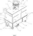
- FIG 1 is an isometric view of the exterior of a feed charging device 20 according to one embodiment of the invention.
- the two main components of the feed charging device 20 visible in Figure 1 are a holding vessel 11 for holding a reserve of a solid particulate feed material, and a windbox 15 for providing a distributed flow of a fluidizing gas to the holding vessel 11. As shown, the holding vessel 11 is located above the windbox 15.
- the feed charging device 20 is shown in Figures 1 and 2 in the approximate orientation in which it is intended to be used.
- the feed charging device 20 is shown as having an overall box-like shape, with the holding vessel 11 and the windbox 15 each having a side wall 22 or 24 comprising four side wall sections.
- the holding vessel 11 has a top wall 26 and the windbox 15 has a bottom wall 28.
- the box-like shape is not essential for proper operation of the feed charging device 20, and that the feed charging device may have any suitable shape, including cylindrical.
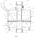
- the holding vessel 11 has an interior chamber 30 for holding a reserve of the solid particulate feed material in a fluidized state, and the windbox 15 encloses a gas distribution chamber 32.
- the interior chamber 30 has an adequate volume to hold a fluidized bed 9 of the particulate feed material in a lower zone 36 of the interior chamber 30, with the interior chamber 30 also including an upper zone 38 which comprises a gas space above the fluidized bed 9, and sometimes called "a freeboard".
- the interior chamber 30 must be of sufficient size to provide a buffer for any material surplus or deficit that results from fluctuations in the upstream elements of the feed system. The sizing of the interior chamber 30 will depend on the fluidization properties of the particulate feed material, and the magnitude of the fluctuations, and should be obvious to anyone skilled in the art.
- the bottom of the holding vessel 11 comprises a bottom partition 13, which also forms a top wall of the windbox 15 and which separates the holding vessel 11 from the windbox 15.
- the bottom partition 13 comprises a plurality of apertures 34 through which the gas distribution chamber 32 is in flow communication with the interior chamber 30 of the holding vessel 11, and through which the fluidizing gas is supplied from the gas distribution chamber 32 to the interior chamber 30.
- the apertures 34 form part of a gas supply means of the feed charging device 20, which is further described below.
- the holding vessel 11 further comprises at least one feed inlet opening 7, through which the feed material is supplied to the interior chamber 30 of the feed flow conditioner 20, for example from a particulate feed duct 40 through which the feed material is fed by gravity to the holding vessel 11.
- the feed charging device 20 is shown in Figure 2 as having one inlet opening 7 located in its side wall 22.
- two or more inlet openings 7 may be provided in different areas of the holding vessel 11, and that the at least one inlet opening may be provided in the side wall 22 or the top wall 26.
- the at least one inlet opening 7 is provided in the side wall 22 of the holding vessel 11 and communicates with the upper zone 38 of the interior chamber 30.
- the feed charging device 20 further comprises at least one outlet opening 2 through which the feed material is discharged from the interior chamber 30 of the holding vessel 11.
- the at least one outlet opening 2 is formed in the wall of an outlet conduit 5, sometimes referred to in this description as "discharge pipe 5".
- the outlet conduit 5 extends through the bottom partition 13 of the holding vessel 11 and extends into the interior chamber 30 thereof. In the illustrated embodiment, the outlet conduit 5 passes through the lower and upper zones 36, 38 of the interior chamber 30 and extends through a wall of the holding vessel 11 in the upper zone 38 of the interior chamber 30.
- outlet conduit 5 extends vertically through the entire height of the holding vessel 11 and extends through an aperture 42 provided in the top wall 26 of the holding vessel 11, with the conduit 5 being sealed to the inner peripheral edge of the aperture 42 in the top wall 26.
- the outlet conduit 5 also extends through an aperture 44 in the bottom wall 28 of the windbox 15 and through the gas distribution chamber 32.
- the outlet conduit 5 therefore provides a flow passage through which the particulate feed material in the fluidized bed 9 is discharged from the device 20.
- the bottom partition 13 comprises a rigid plate which may be substantially flat and horizontally oriented, also sometimes referred to herein as a "fluidizing plate 13".
- the bottom partition 13 is not necessarily flat and horizontal. Rather, the bottom partition 13 may be sloped and/or may have a dished or conical shape.
- the outlet conduit 5 is shown in the drawings as being centered within the feed charging device 20 around the discharge pipe 5. It can be appreciated that the outlet conduit 5 does not necessarily need to be centered within the feed charging device 20.
- the position of outlet conduit 5 may be biased such that it is further away from the at least one inlet opening 7.
- the outlet conduit 5 will be spaced from the side wall 22 of holding vessel 11 such that it is surrounded on all sides by the fluidized bed 9 of particulate feed material in the lower zone 36 of the interior chamber 30.
- the interior chamber 30 of the holding vessel 11 communicates with the discharge pipe 5 through the at least one outlet opening 2 and is in flow communication with the fluidized bed 9 of particulate feed material in the lower zone 36.
- the at least one outlet opening 2 comprises a permanent aperture slit of fixed height, and which is horizontally oriented and extends continuously around substantially the entire outer perimeter of the conduit wall 46 of discharge pipe 5.
- the at least one outlet opening 2 is adapted to receive the feed material from a plurality of radial directions, and more specifically is adapted to receive the feed material along substantially the entire outer perimeter of the conduit wall 46.
- This radial inflow of feed material through the at least one outlet opening 2 provides an axisymmetric and spatially uniform discharge of particulate feed from the bottom end of feed flow conditioner 20, which is integrated to equipment requiring particulate feed, for example a concentrate burner of a flash smelting furnace (not shown).
- the top end of discharge pipe 5 may connect to off-gas ducting or possibly an alternate feed bypass chute (not shown), which would allow maintenance of the feed charging device while allowing feed to continue to supply the equipment downstream (below device 20).
- the at least one outlet opening 2 is shown as comprising a single, continuous aperture slit, it will be appreciated that other configurations are possible.
- the at least one outlet opening 2 may comprise a plurality of openings or slits which are spaced apart along substantially the entire outer perimeter of the conduit wall 46, such that the at least one outlet opening 2 is open to the lower zone 36 of the interior chamber 30, and the fluidized bed 9 located therein, along substantially the entire outer perimeter of the conduit wall 46.
- the at least one outlet opening 2 comprises a plurality of openings or slits, they are separated by webs which may be integral with the wall 46 of the outlet conduit 5.
- the holding vessel 11 is designed to provide adequate capacity to allow some self-regulation of the fluidized bed 9 level movement. In other words, if the feed rate from the feed inlet 7 is increased, the fluidized bed 9 level will rise, which will increase the discharge flow of particulate feed through the at least one outlet opening 2, without a requiring a change to any other operating parameters.
- the at least one outlet opening 2 is located in close proximity to the bottom partition 13, and a bottom threshold of the at least one outlet opening 2 is formed by a replaceable baffle ring 17, which prevents coarse particles within the fluidized bed 9 of particulate feed material from partially or completely blocking the at least one outlet opening 2.
- the baffle ring 17 also reduces local effects of the fluidizing gas on the discharge path created by the at least one aperture 34.
- the area of the at least one outlet opening 2 is adjustable.
- the outlet conduit 5 in which the at least one outlet opening 2 is formed may include a continuously slidable cover member which is movable from a first position in which the area of the at least one outlet opening 2 is at a maximum, to a second position in which the area of the at least one outlet opening 2 is at a minimum, or even fully closed.
- the slidable cover member may be a vertically moving or rotating component used to adjust the area of the at least one outlet opening 2, or any other means of adjusting the outlet opening 2 can be used.
- the outlet conduit 5 may comprise a cylindrical sliding sleeve 4.
- the sleeve 4 is vertically (longitudinally) slidable along a surface of the outlet conduit 5 between the first and second positions, such that the slit 2 has a greater height with the sleeve 4 in the first position than in the second position.
- the sliding sleeve 4 is sandwiched between the outer fixed layer of the outlet conduit 5 and an internal fixed layer 3, allowing a variable aperture slit 1 to form in the outlet conduit 5, and effectively reducing the area of the continuous slit comprising the at least one outlet opening 2.
- Figure 3 illustrates the second position of the sliding sleeve 4, wherein the effective open area of the at least one outlet opening 2 is at a minimum, but the at least one outlet opening 2 remains partially open.
- the first position is defined where the sliding sleeve 4 is raised so that the variable aperture slit 1 has an area at least equal to the area of the at least continuous slit 2.
- variable aperture slit 1 allows the axisymmetric and spatially uniform discharge feed rate to be controlled, and can be increased in height and area to increase the discharge rate (up to a maximum area equal to that of the at least one outlet opening 2), or reduced to decrease the discharge rate by moving the cylindrical sliding sleeve 4.
- the movement of the cylindrical sliding sleeve 4 is controlled by an actuation mechanism 6 for moving the sliding sleeve 4 between the first and second positions.
- the actuation mechanism 6 is located above the feed flow conditioner 20 and comprises a power screw, which converts the rotational motion of the motor to the vertical motion required of the cylindrical sliding sleeve 4 in this embodiment. It can be appreciated that any actuation mechanism 6, positioned at any location, can be used to adjust the outlet opening area.
- the windbox 15 may be supplied with the fluidizing gas through a fluidizing gas inlet nozzle 14, and is separated from the holding vessel 11 by the bottom partition 13, which may be in the form of a fluidizing plate.
- the fluidizing plate 13 contains a plurality of apertures 34, which may be defined by a plurality of high precision tuyeres 12, which allow the fluidizing gas to enter the holding vessel 11, as shown in Figures 2-3 .
- the tuyeres 12 are received in the bottom partition 13 in spaced relation to one another, and may be radially dispersed around the conduit wall of the outlet conduit 5, so as to provide a substantially uniform circumferential fluidization and suspension of the particulate feed within the lower portion 36 of interior chamber 30.
- the windbox 15 provides uniform distribution of the fluidizing gas throughout the gas distribution chamber 32, thereby distributing the fluidizing gas across substantially the entire fluidizing plate 13 before it enters the tuyeres 12.
- bottom partition 13 may be partially or entirely comprised of one or more porous pads or porous membranes, and wherein the apertures 34 of bottom partition 13 are defined by the porous pads or porous membranes.
- the holding vessel 11 further includes at least one off-gas outlet opening 10, which is provided in the conduit wall of the outlet conduit 5, and allows the fluidizing gas to be discharged from the device 20.
- the at least one off-gas outlet opening 10 is located above the height of the fluidized bed 9 of particulate feed, in communication with the upper zone 38 of interior chamber 30. This allows the collecting of elutriated fines that are carried with the off-gas from the fluidized bed 9, which will be discharged downwards through the discharge pipe 5, with the rest of the particulate feed.
- a deflector plate 8 is positioned in the upper zone 38 of interior chamber 30 between the feed inlet opening 7 and the off-gas outlet opening 10.
- the deflector plate 8 eliminates short circuiting of fines from the feed inlet 7 to the at least one off-gas outlet opening 10.
- the deflector plate 8 may be oriented substantially vertically and the lower edge of the deflector plate 8 may be submerged into the fluidized bed 9, as shown in Figure 2 , to prevent the exhaust of the fluidizing gas to the feed inlet 7 and protect the upstream feed equipment from dust.
- actuated valves mounted externally to the feed charging device 20 are governed by a PLC (programmable logic control) or other mechanical or electronic feedback controller and control the volumetric flow rate of the fluidizing gas, maintaining a required fluidization velocity in the bed 9 using feedback from a pressure sensor (not shown) positioned within the bottom zone 36 of the fluidized bed 9 immediately above the fluidizing plate 13. If required the flow rate of the fluidizing gas can be used to control the discharge rate of the particulate feed into the outlet conduit 5, along with the adjustment of the area of outlet opening 2.
- PLC programmable logic control
- the flow rate of the fluidizing gas can be used to control the discharge rate of the particulate feed into the outlet conduit 5, along with the adjustment of the area of outlet opening 2.
- Pressure sensors are also located in the holding vessel 11, in the freeboard above the fluidized bed 9 level of particulate feed, as well as at the bottom of the fluidized bed 9, immediately above the bottom partition 13. This arrangement measures the pressure drop through the fluidized bed 9 and provides feedback to the PLC. This data is used to monitor the weight of the particulate feed within the feed flow conditioner 20, as well as the level of fluidized bed 9.
- the PLC can adjust the outlet opening 2 by, for example, changing the height of the variable aperture slit 1, or flow rate of the fluidizing gas, to control the discharge rate of the particulate feed through the outlet conduit 5.
- Load cells 16 are placed at the bottom of the feed flow conditioner to support and accurately measure the weight of the feed flow conditioner 20 and its contents.
- the load cells 16 can be used to accurately measure/calibrate the mass flow rate of the particulate feed through the feed flow conditioner 20, by deliberately stopping the flow of particulate feed to the inlets 7 for a short period of time and measuring the rate of weight loss.
- the load cells 16 can effectively monitor the fluidized bed 9 level.
- the feed flow conditioner can utilize expansion joints 18 that isolate the feed flow conditioner 20 from the burner downstream (below device 20), as well as the off-gas equipment upstream (above device 20).
- the expansion joints 18 isolate the feed flow conditioner 20 from the rest of the system and allow the weight of the feed flow conditioner 20 and its contents to be accurately weighed by the load cells 16.
- the expansion joints 18 also allow thermal expansion of the feed flow conditioner 20 and are connected to the feed flow conditioner 20 other equipment such as a burner, feed and off-gas ducts.
- Both the windbox 15 and holding vessel 11 contain multiple access ports for inspection, cleaning and adjustment of the internals, the ports being covered by plates 47 when the device 20 is in use.
- the tuyeres 12 used to inject fluidizing gas into the holding vessel 11 can be individually controlled, or they can be controlled in groups or clusters.
- the apertures 34 in the fluidizing plate 13 may contain porous ceramic pads or a porous membrane, or the bottom partition 13 can be fabricated as a frame holding porous material such as a fabric type, which has sealed connection to the frame.
- the discharge direction and velocity of the fluidizing gas could also be adjusted, mechanically or by other means.
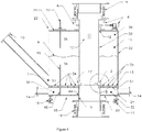
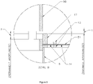
- Figures 4 and 5 illustrate a second embodiment of the invention, with Figure 5 providing a detail view of the outlet area shown in Figure 4 .
- Similar components as those shown in Figure 1-3 are given like reference numbers, and their description will not be repeated. Only components differing from the first embodiment shown will be described to provide examples of the additional features or variations of the design that are discussed herein.
- the feed inlet opening 7 is positioned close to the bottom of the holding vessel 11 and close to fluidizing plate 13, so the feed is introduced into the holding vessel 11 below the top of the fluidized bed 9.
- the windbox 15 is separated from the holding vessel 11 by the bottom partition 13, which is in the form of two fluidizing plates that sandwich a porous membrane 51 in between.
- the bottom partition 13 contains a plurality of apertures 34, in both plates, which allow the fluidizing gas to enter the holding vessel 11 through the porous membrane 51.
- the bottom partition 13 may instead comprise a single apertured plate 34 with tuyeres 12, as in the first embodiment.
- the windbox 15 consists of separate compartments, which are separated and sealed by a divider plate 49. Each of the compartments is supplied with fluidizing gas from separate fluidizing gas inlet nozzles 14.
- a permanent baffle plate 48 is positioned on the top surface of the fluidizing plate 13 and protrudes into the fluidized bed 9.
- the position and shape of the baffle plate 48 can be modified to optimize the feed distribution from the feed inlet 40 along the holding vessel 11 to achieve uniform residence time for the particulate in the holding vessel 11.
- the upper edge of the baffle plate 48 is located within the fluidized bed 9, i.e. in the lower zone 36.
- the baffle plate 48 and the windbox divider plate 49 at least partially define a feed inlet zone 53 within the chamber 30 of vessel 11, and that the separation of the windbox 15 into separate compartments allows different amounts of fluidizing gas to be supplied to the fluidized bed within the feed inlet zone 53.
- This arrangement allows the particulate feed entering at the feed inlet 7 to be pneumatically elevated, minimizing elutriation of dust in the freeboard due to the freefall of particulate material through the feed inlet 7. This also minimizes fluidizing gas percolation into the feed inlet 7.
- the feed inlet zone 53 functions as a check on the flow of feed into the fluidized bed 9. By connecting feed inlet 7 directly to a feed bin, and varying the flow of air to the windbox compartment 32 in this arrangement, the feed flow conditioner 20 can also be used as a feeder.
- a deflector plate 52 is positioned in the upper zone 38 of interior chamber 30 between the feed inlet opening 7 and the off-gas outlet opening 10.
- the deflector plate 52 extends downwardly from top wall 26 and is positioned with its lower edge located above the fluidized bed 9 and above the upper edge of baffle plate 48 to provide a passage for flow of gas and particulates out of the feed inlet zone 53 and into the main portion of chamber 30.
- the position and shape of deflector plate can be modified to minimize the amount of dust that enters the holding vessel 11 or the off-gas vents 10 from the feed inlet opening 7.
- the feed charging device 20 further comprises at least one outlet opening 2 through which the feed material is discharged from the interior chamber 30 of the holding vessel 11.
- the at least one outlet opening 2 is formed in the wall of a sliding outlet conduit 50, and in this embodiment comprises a plurality of openings that are separated by webs 55 which are integral with the wall of the sliding outlet conduit 50.
- the sliding outlet conduit 50 passes through the lower and upper zones 36, 38 of the interior chamber 30, extends vertically through the entire height of the holding vessel 11, and extends through an aperture 42 provided in the top wall 26 of the holding vessel 11, with the sliding outlet conduit 50 being sealed to the inner peripheral edge of the aperture 42 in the top wall 26.
- the sliding outlet conduit 50 extends downwards through the baffle ring 17, and may extend downwardly through the bottom partition 13, the sliding conduit 50 being sealed to the inner peripheral surface of the baffle ring 17.
- the sliding outlet conduit 50 is positioned such that the outlet openings 2 are located in close proximity to the bottom partition 13, and the replaceable baffle ring 17.
- the outlet openings 2 can be movable from a first position away from the baffle ring 17 in which the area of the outlet openings 2 is open and at a maximum, to a second position in which the area of the at least one outlet opening 2 is constricted by the baffle ring 17 to a minimum.
- the sliding outlet conduit 5, together with baffle ring 17, thus define a variable aperture 1.
- Figure 4 shows the area of the variable aperture 1 at a minimum, with most of the area of the outlet opening 2 being covered by the baffle ring 17.
- Figure 5 also shows the minimum area (dimension of variable aperture 1 on right side of Fig. 5 ) and the maximum area (dimension of permanent aperture 2 on left side of Fig. 5 ) of the outlet opening, which is equal to the area of the at least one outlet opening 2.
- the movement of the sliding outlet conduit 50 is controlled by an actuation mechanism 6 which may be the same as the actuation mechanism 6 described above.
- the off-gas discharge opening 10 can be at the top of the holding vessel 11 and can be equipped with a bin vent dust collector (not shown).
- the holding vessel 11 would contain a plurality of feed inlet openings 7 to supply particulate feed.
- Such a configuration would allow a feed flow conditioner 20 to be positioned on top of an existing concentrate burner, with the feed supply system interfacing with the feed inlets. This arrangement would allow a bypass valve to divert the particulate feed from the feed supply system directly through the top of the outlet conduit 5, allowing maintenance to occur on the feed flow conditioner 20 without taking it offline.
- Figure 7 provides a cross-sectional view of a further example. Similar components as those shown in Figure 1-5 are given like reference numbers, and their description will not be repeated. Only components differing from the first or second embodiments will be described to provide examples of the additional features or variations of the design that are discussed herein.
- Figure 8 provides a detail view of the outlet area shown in Figure 7 .
- the example of Figure 7 includes a feed inlet zone 53 similar to that described above in connection with Figures 4 and 5 .
- the feed inlet zone 53 comprises a separate fluidized feeding compartment 531, with an independent inlet windbox 151 which corresponds in function to the separate compartment of windbox 15 under the feed inlet zone 53 in the second embodiment shown in Figure 4 .
- the holding vessel 11 contains a permanent baffle plate 48 that is positioned within the fluidized bed 9, between the fluidized feeding compartment 531 and the interior chamber 30. The height of the baffle plate 48 can be below or above the level of the fluidized bed.
- the feed charging device 20 of Figure 7 further comprises at least one outlet opening 2 through which the feed material is discharged from the interior chamber 30 of the holding vessel 11.
- the at least one outlet opening 2 is formed in the wall of holding vessel 30, and is located above the fluidizing plate 34 as in the first two embodiments.
- the area of outlet opening 2 is varied by a valve mechanism 500, which comprises a section of a cylinder with a flat face, and which is rotatable about a horizontal axis.
- the size of the outlet opening 2 can be varied by rotating the partially-cylindrical valve mechanism 500 about its axis between two angular positions, to define a variable aperture 1.
- Figure 7 shows the valve mechanism 500 in a partially closed position which defines the minimum area of variable aperture 1.
- Figure 8 illustrates the valve in a partially closed position. Rotating the valve mechanism 500 counter-clockwise about its axis creates a rectangular variable aperture 1 between the edge of the valve mechanism 500 and the floor of the discharge chute 501.
- the maximum opening of the variable aperture 1 is defined by allowed angular rotation limits and dimensions of the partially-cylindrical valve mechanism 500 and in this embodiment will be defined by an orientation where the flat face of the valve mechanism 500 is oriented horizontally.
- variable aperture 1 allows the rectangular spatially uniform discharge feed rate to be controlled, and can be increased in height and area to increase the discharge rate by rotating the valve mechanism 500 counter clockwise, or reduced to decrease the discharge rate by rotating the valve mechanism 500 clockwise.
- the movement of the valve mechanism 500 is controlled by an actuation mechanism (not shown) for rotating the valve mechanism 500.
- valve mechanism 500 can be replaced by other known actuated valves, such as knife gates or slide gates, to form an outlet aperture 1 of any desired plane shape.
- the windbox 15 may consist of separate compartments, with each containing a specific arrangement of tuyeres 12 in the fluidized plate 34 to allow modification of the fluidizing characteristics within the holding vessel 11.
- variable aperture slit 1 can be replaced by a series of holes or slot openings, where the adjustment of the aperture cross-sectional area can be an internal sleeve controlled either vertically or rotationally.
- feed charging devices for a flash smelting furnace including an elevated reaction shaft having a burner where particulate feed material and reaction gas are brought together and reacted.
- the devices described below could be adapted for use in other fields using particulate feed systems, such as in the pharmaceutical, chemical and food production and processing industries.
- FIG. 6 illustrates a further embodiment of the invention and a possible configuration of a flash smelter furnace 100 with a burner 110 and feed flow conditioner 20, sometimes referred to herein as a "feed charging device".
- the feed flow conditioner 20 of Figure 6 may take the form of any of the feed flow conditioners according to the first three embodiments, or variants thereof. Similar components as those shown in Figures 1-5 , 7 and 8 are given like reference numbers, and their description will not be repeated. Only components differing from the first three embodiments will be described to provide examples of the additional features or variations of the design that are discussed herein.
- the feed charging device 20 comprises a holding vessel 11 and is shown as having a feeding compartment 531 for receiving feed from a conventional feeding system (not shown) through feed ducts 40.
- the feed charging device 20 integrates directly with the top of a concentrate burner 110. This arrangement allows feed material to be charged directly to the burner 110 via the charging device 20, or an alternative pathway through the bypass chutes 120.
- the feed charging device 20 delivers feed directly to the burner 110, eliminating both feed fluctuations and spatial non-uniformity.
- FIG 9 illustrates a further embodiment of the invention and a possible configuration of a flash smelter furnace 100 with a burner 110 and feed flow conditioner 20, sometimes referred to herein as a "feed charging device". Similar components as those shown in Figures 1-8 are given like reference numbers, and their description will not be repeated. Only components differing from the first four embodiments will be described to provide examples of the additional features or variations of the design that are discussed herein.
- the feed charging device 20 comprises a holding vessel 11 and includes two separate feeding compartments 532, each of which may be similar to the feeding compartments 531 described above, for receiving feed from a conventional feeding system (not shown) through feed ducts 40.
- the feed charging device 20 integrates with a concentrate burner 110 via an intermediate conveying apparatus 201, in this case, an air-slide. This arrangement allows feed material to be charged to the burner via the charging device 20, or an alternative pathway through the bypass chutes 120.
- the feed charging device 20 will eliminate feed fluctuations and provide spatially uniform feed to the burner feed chute.
- the ultimate spatial distribution of the feed will be impacted by the design of the mechanical components distributing the feed within the burner. This disadvantage is, to some extent, offset by the ease with which the embodiment shown in Figure 9 can be integrated into an existing flash furnace burner feed system.
- the charging device can be configured to feed burners with multiple inlets or multiple burners through multiple variable apertures.
- Various inlet configurations can be utilized to adapt the charging device to existing feed systems.
- a method for improving the combustion characteristics of a flash smelting burner by improving the temporal and spatial uniformity of the feed distribution supplied to the combustion space of a flash furnace, by the application of a fluidized holding vessel with a feedback-controlled discharge aperture as described above. This method will be further illustrated using the example below, which was simulated using a combination of transient computational fluid dynamics (CFD) modeling and computational particle fluid dynamics (CPFD) modeling.
- CFD transient computational fluid dynamics
- CPFD computational particle fluid dynamics
- a flash smelting furnace operating with a conventional feed system was simulated using an axisymmetric transient CFD model. Details of the modeling work can be found in a paper by Lamoureux et al. entitled "Impact of Concentrate Feed Temporal Fluctuations on a Copper Flash Smelting Process", http://onlinelibrary.wiley.com/doi/10.1002/9781118887998.ch52/summary .
- the response of the feed flow conditioner to low frequency feed intermittency at the inlet was simulated using commercial CPFD software.
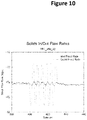
- the results, illustrated in Figure 10 clearly show that the feed flow conditioner has a high capacity to attenuate the amplitude of low-frequency feed intermittency introduced at its inlet. This indicates that the feed flow conditioner can, when introduced between a burner and a conventional feed system, reduce the impact of feed intermittency inherent in the conventional feed systems, thereby improving burner performance.
- burners for flash smelting furnaces While the above subject matter has been described in the context of burners for flash smelting furnaces, it will be appreciated that it may also have application to other burners for particulate feed materials, such as burners for furnaces that are fueled by particulate coal, or other equipment requiring particulate feed.
Landscapes
- Engineering & Computer Science (AREA)
- Mechanical Engineering (AREA)
- General Engineering & Computer Science (AREA)
- Chemical & Material Sciences (AREA)
- Combustion & Propulsion (AREA)
- Dispersion Chemistry (AREA)
- Devices And Processes Conducted In The Presence Of Fluids And Solid Particles (AREA)
- Manufacture And Refinement Of Metals (AREA)
- Furnace Charging Or Discharging (AREA)
- Filling Or Emptying Of Bunkers, Hoppers, And Tanks (AREA)
- Processing And Handling Of Plastics And Other Materials For Molding In General (AREA)
- Fodder In General (AREA)
Description
- The present subject matter relates to fluidized feed bin systems for use with particulate feed materials. The system described herein could be applied in fields such as flash smelting, pharmaceuticals, or any other field where uniformity of feed flow in time, space and particle size distribution (PSD) is important.
- There are numerous fields in which a particulate feed material must be uniformly distributed and introduced into a device, with respect to both time and space, while maintaining a well-mixed and steady particle size distribution within the feed stream.
- A group of such applications concerns the delivery of particulate materials such as pulverized coal, dust or combustible ores to a combustion system, such as may be found in burners for heat generation, insufflation or smelting.
- One such application that requires uniformity of feed flow is flash smelting for sulphide concentrates, such as may be encountered in the production of copper, nickel, lead or zinc. A flash smelting furnace typically includes an elevated reaction shaft at the top of which is positioned a burner or multiple burners where particulate feed material and reaction gas are brought together. In the case of copper smelting, the feed material is typically an ore concentrate containing both copper and iron sulfide minerals. The concentrate is usually mixed with a silica flux and combusted with pre-heated air or oxygen-enriched air. Molten droplets are formed in the reaction shaft and fall to the hearth, forming a copper-rich matte and an iron-rich slag layer.
- A conventional burner for a flash smelter includes an injector having a water-cooled sleeve and an internal central lance, a windbox, and a cooling block that integrates with the roof of the furnace reaction shaft. The lower portion of the injector sleeve and the inner edge of the cooling block create an annular channel. Oxygen enriched combustion air enters the windbox and is discharged to the reaction shaft through this annular channel. The water-cooled sleeve and the internal lance of the injector also create an annular channel within the combustion air flow annulus. The feed material is introduced from above and descends through the injector sleeve into the reaction shaft through this internal annulus. Deflection of the feed material into the reaction gas is promoted by a bell-shaped tip at the lower end of the central lance. In addition, the tip includes multiple perforation jets that direct compressed air outwardly to disperse the feed material in an umbrella-shaped reaction zone. Such a burner for a flash smelting furnace is disclosed in
U.S. patent no. 6,238,457 . - The material feed supply equipment is typically comprised of bins and hoppers, mechanical feeders, conveyors, splitter boxes, manifold connectors, and feed pipes located above the injector. Typical feeders and conveyors include screw-feeders, table feeders, drag-chain conveyors and air slides. Some feed systems also combine feed streams of different particle density, shape, and size upstream of the burner.
- Known feed systems of this type are associated with disadvantages that can adversely affect the burner performance and cause problems, such as: poor oxygen efficiency; variable furnace metallurgy and matte grade; increased copper losses to slag; increased elutriation of dust to the off-gas handling equipment, etc. These problems result from a failure to achieve uniformity of the feed material both spatially and in time on the appropriate scales, as well as causing segregation of the individual feed components with respect to particle size, density and/or shape.
- For example, it is well documented that known mechanical feed systems, such as drag chains, screw conveyors and table feeders deliver the feed in discrete packets of material, resulting in low-frequency feed pulsations in the delivery of feed material to the burner, causing incomplete combustion. Such a system and the associated problem is described in Suenaga et al., "High-Performing Flash Smelting Furnace at Saganoseki Smelter & Refinery", Second International Conference on Processing Materials for Properties, The Minerals, Metals & Materials Society, 2000, pages 879-884.
- It is also well documented that known feed systems suffer from periodic flow instabilities associated with uncontrollable partial fluidization of the charge in the feed bins. This normally occurs during the charging cycle of the bin, and results in uncontrolled delivery of feed material to the burner, typically lasting between one and several minutes. This has negative consequences on all aspects of the combustion process.
- While air-slides and alternative bin designs have been proposed to address the above issues, these approaches suffer from serious drawbacks: Air-slides are incapable of eliminating low-frequency feed pulsations, serving instead to transmit them to the burner. Alternative bin designs, typically with a mass-flow hopper, can reduce the severity of the flushing phenomenon, but are typically large, or severely decrease the capacity of the bin for a given bin height or footprint. This makes retrofit of the alternative bins into existing feed systems costly and impractical.
- Another example of a typical feed problem faced by concentrate burners is poor distribution of feed around the circumference of the burner. Feed systems usually contain one or more feed pipes that interface with the injector and attempt to utilize splitter boxes, guides and diverter chutes to distribute feed evenly around the circumference. Such systems tend to cause the feed to gather at corners/edges of the chute walls and fins, forming dense, "ropes" of feed within the plume. This lack of spatial uniformity results in poor ignition characteristics, non-uniformity of the combustion plume and reduced oxygen efficiency.
- Pneumatic conveying systems have been proposed in an attempt to resolve both the pulsation problems, but these require a large investment of capital for new equipment, as well as substantial modifications to existing building layouts to accommodate the system. These systems do not, however, eliminate the problem of non-uniform circumferential distribution of the feed at the burner inlet, because they feed through intermediate, feed chutes, splitters or other equipment, and deliver the feed through discrete points around the circumference of the burner, necessarily leading to a lack of uniformity.
- The process disturbances caused by temporally and spatially non-uniform delivery of the feed to flash smelting burners represent a significant loss of economic value to the flash smelter operator. None of the existing technologies adequately solves the problem of feed delivery. There thus remains a need for feed systems for flash smelting furnaces, or other applications using a particulate feed material, which provide uniform flow, both spatially and in time, around an inlet annulus with minimum particle segregation effects and in which the feed rate can be accurately controlled.
-
Wo 2012/115062 A1 relates to a powder feeding system for feeding powder in a feed tank via a valve for powder downstream of the feed tank and through a powder delivery pipe, the powder feeding system including: a powder fluidizing portion provided in the feed tank and configured to introduce fluidizing gas for fluidizing the powder; and a powder refluidizing portion provided between the powder fluidizing portion and the valve for powder and configured to introduce refluidizing gas for refluidizing the powder. - The invention is defined by
claim 1. - The following summary is intended to introduce the reader to the more detailed description that follows, and not to define or limit the claimed subject matter.
- In some examples, the feed charging device further comprises a bottom partition having a plurality of apertures, wherein the gas supply means comprises a gas distribution chamber which is separated from the interior chamber of the holding vessel by said bottom partition, wherein the gas distribution chamber has an inlet for receiving said fluidizing gas, and wherein an interior of the gas distribution chamber is in flow communication with the interior chamber of the holding vessel through the plurality of apertures in the bottom partition.
- In some examples, the gas distribution chamber is enclosed within a windbox, and wherein the bottom partition forms a top wall of the windbox. The gas distribution chamber may comprise a plurality of compartments, each of said compartments being in flow communication with a portion of the interior chamber of the holding vessel through a subset of the plurality of apertures in the bottom partition.
- In some examples, the feed charging device further comprises a baffle plate located inside the interior chamber in close proximity to the at least one inlet opening, wherein the baffle plate is mounted to the bottom partition to permit pneumatic elevation of the particulate feed material from bottom to top.
- In some examples, the gas supply means is selected from the group consisting of tuyeres, porous pads and porous membranes. For example, the gas supply means may comprise a plurality of said tuyeres which are received in said bottom partition in spaced relation to one another, and wherein the apertures are defined by said tuyeres. Alternatively, the bottom partition may comprise one or more of said porous pads or porous membranes, and wherein the apertures are defined by said porous pads or porous membranes.
- In some examples, the lower zone of the holding vessel defines an area to be occupied by a fluidized bed of said particulate feed material, and wherein the interior chamber also includes an upper zone which comprises a gas space above said fluidized bed. For example, the at least one inlet opening is provided in the lower zone of the interior chamber, and is located below a bed level of the fluidized bed to allow introduction of the particulate feed material into the fluidized bed below the bed level.
- In some examples, the feed charging device further comprises at least one off-gas outlet opening provided in the interior chamber of the holding vessel, in communication with the upper zone of the interior chamber. For example, the feed charging device may further comprise at least one deflector plate, at least a portion of which is located in the upper zone of the interior chamber, between the at least one inlet opening of the holding vessel and the at least one off-gas outlet opening. The at least one deflector plate may be oriented substantially vertically and has a lower end which extends into the lower zone. The at least one deflector plate may be oriented substantially vertically and has a lower end which is spaced above the lower zone.
- In some examples, the outlet conduit may pass through the lower and upper zones of the interior chamber, and wherein the at least one off-gas outlet opening is provided in a conduit wall of the outlet conduit.
- The outlet conduit has a conduit wall in which said at least one outlet opening is formed. The outlet conduit extends substantially vertically through said interior chamber, wherein said gas supply means are radially dispersed around the outlet conduit. The at least one outlet opening is arranged to receive said feed material from a plurality of radial directions. The conduit wall of the outlet conduit may have an outer perimeter, and wherein said at least one outlet opening is open to the lower zone of the interior chamber along substantially the entire outer perimeter of the conduit wall. For example, the at least one outlet opening may comprise a plurality of openings spaced apart along substantially the entire outer perimeter of the conduit wall; or the at least one outlet opening may comprise a horizontal slit extending throughout substantially the entire outer perimeter of the conduit wall.
- In some examples, the at least one outlet opening is separated from a bottom of said interior chamber by a baffle ring having a height sufficient to prevent coarse particles within said particulate feed material from blocking said at least one outlet opening.
- I An area of the at least one outlet opening is adjustable.
- The outlet conduit includes a slidable or rotatable cover member adapted to be moved steplessly or in discrete steps from a first position in which the area of the at least one outlet opening is at a maximum, to a second position in which the area of the at least one outlet opening is at a minimum.
- The feed charging device further comprises an actuation mechanism for controlling the movement of the cover member between said first position and said second position. The at least one outlet opening comprises a horizontal slit extending throughout substantially the entire outer perimeter of the conduit wall, wherein the cover member comprises a sleeve which is slidable longitudinally along a surface of the outlet conduit between said first position and said second position, and wherein the horizontal slit has a greater height with the sleeve in the first position than in the second position.
- In some examples, the feed charging device further comprises a plurality of sensors to measure a pressure drop of the particulate feed material in the interior chamber of the holding vessel.
- In some examples, the feed charging device further comprises multiple actuated valves mounted externally of the holding vessel, a pressure sensor located in the lower zone and an electronic feedback controller for controlling the valves, so as to control a volumetric flow rate of the fluidizing gas into the interior chamber and maintain a required fluidization velocity using feedback from the pressure sensor, wherein the flow rate of the fluidizing gas is optionally used to control a discharge rate of the particulate feed material.
- In some examples, the at least one outlet opening is provided in a side wall of the holding vessel.
- In some examples, the side wall in which the at least one outlet opening is provided is distal to the at least one inlet opening. For example, the at least one outlet opening may be open to the lower zone of the interior chamber. The at least one outlet opening may comprise one or more openings located along a base of the side wall. The at least one outlet opening may comprise a horizontal slit extending along the base of the side wall. The at least one outlet opening may be spaced from a bottom of said interior chamber by a height sufficient to prevent coarse particles within said particulate feed material from blocking said at least one outlet opening. The area of the at least one outlet opening is adjustable.
- The at least one outlet opening includes a slidable or rotatable cover member adapted to be moved steplessly or in discrete steps from a first position in which the area of the at least one outlet opening is at a maximum, to a second position in which the area of the at least one outlet opening is at a minimum. The feed charging device r comprises an actuation mechanism for controlling the movement of the cover member between said first position and said second position. The at least one outlet opening comprises a horizontal slit, and wherein the cover member may comprise a valve member which is rotatable between said first position and said second position, and wherein the horizontal slit has a greater height with the sleeve in the first position than in the second position.
- In some examples, an area of the at least one outlet opening is adjustable, and wherein the feed charging device further comprises: at least one sensor for measuring, directly or indirectly, a quantity of said particulate feed material inside the interior chamber; and means for controlling the area of the at least one outlet opening in response to changes in the quantity of said particulate feed material inside the interior chamber.
- Said means for controlling the area of the at least one outlet opening comprises a slidable or rotatable cover member adapted to be moved steplessly or in discrete steps from a first position in which the area of the at least one outlet opening is at a maximum, to a second position in which the area of the at least one outlet opening is at a minimum.
- Said means for controlling the area of the at least one outlet opening further comprises an actuation mechanism for controlling the movement of the cover member between said first position and said second position.
- In some examples, the feed charging device is for a flash smelting furnace including an elevated reaction shaft having a burner, and wherein the outlet conduit is attached to the upper end of the burner, above a reaction shaft where the particulate feed material is reacted with a reaction gas.
- In some examples, which are not claimed there is provided method for improving the combustion performance of a flash smelting concentrate burner by improving the spatial and temporal uniformity of the feed entering the burner, the method comprising: (a) providing a holding vessel having an interior chamber, the holding vessel having an interior chamber, at least one inlet opening and at least one outlet opening; (b) feeding a solid particulate feed material into the interior chamber through said at least one inlet opening; (c) fluidizing the feed material in a lower zone of the interior chamber by injecting a fluidizing gas into the lower zone of the chamber; (d) discharging the fluidized feed material through the at least one outlet opening, wherein the at least one outlet opening is in flow communication with the lower zone of the interior chamber.
- In some examples, the method further comprises: measuring, directly or indirectly, a quantity of said particulate feed material inside the interior chamber.
- In some examples, the method further comprises: controlling an area of the at least one outlet opening in response to changes in the quantity of said particulate feed material inside the interior chamber.
- According to another aspect, a feed flow conditioner is provided for a flash smelting concentrate burner, which integrates with a reaction shaft of a furnace. The feed flow conditioner includes a holding vessel, feed supply inlets, a discharge aperture, a fluidizing plate, a windbox, and fluidizing gas supply system. The holding vessel integrates with the burner feed chute, and has a discharge aperture there through to communicate with the feed chute of the burner via an intermediate conveying apparatus, such as a chute or air-slide. The feed supply inlets are mounted over the holding vessel and supply the feed flow conditioner with particulate feed. The discharge aperture, which is in the form of one or more openings arranged in one or more walls of the holding vessel may allow flow of the particulate feed into the conveying apparatus. The fluidizing plate, which forms the bottom of the holding vessel, contains a plurality of gas distributors such as tuyeres, porous pads, or porous membrane to supply the holding vessel with fluidizing gas, which fluidizes the particulate feed, creating a suspension of feed within the holding vessel, thereby promoting the flow of the particulate feed through the aperture and into the feed chute of the burner via the conveying apparatus. The windbox, which is mounted underneath the fluidizing plate, is fitted with a fluidizing gas supply system to deliver and distribute fluidizing gas throughout the entire windbox.
- According to another aspect which is not claimed, a method for improving the combustion performance of a flash smelting concentrate burner is provided, which delivers feed to a flash smelting concentrate burner with low spatial non-uniformity and with greatly reduced low-frequency fluctuations, regardless of the spatial and temporal flow characteristics of the feed delivered upstream of the system. The method utilizes a fluidized holding vessel with sufficient buffer capacity to absorb any fluctuations in the incoming feed. The discharge rate of the holding vessel is controlled, in response to operator input or long-term changes in the incoming feed rate. Control of the discharge rate is achieved by manually or automatically adjusting the aperture size, the fluidizing air flow rate, or the height of the fluidized bed.
- In some examples, the discharge aperture is one or more holes or slots that are arranged in one or more of the walls of the holding vessel.
- In some examples, the discharge aperture opening height can be modified through the use of an adjustable gate to control the discharge rate.
- In order that the claimed subject matter may be more fully understood, reference will be made to the accompanying drawings, in which:
-
Fig. 1 is an isometric view of a feed flow conditioner according to one embodiment. -
Fig. 2 is a cross-sectional view of the first embodiment of a feed flow conditioner. -
Fig. 3 is a detailed view of the adjustable aperture shown in the first embodiment of a feed flow conditioner. -
Fig. 4 is a cross-sectional view of a second embodiment of a feed flow conditioner. -
Fig. 5 is a detailed view of the adjustable aperture and porous membrane shown in the second embodiment of a feed flow conditioner. -
Fig. 6 is a typical layout of flash smelter furnace, showing the burner and feed flow conditioner in a possible arrangement. -
Fig. 7 is a cross-sectional view of a third example not falling under the scope ofclaim 1 the feed flow conditioner with the aperture located on one of the walls of the holding vessel. -
Fig. 8 is a detailed view of the adjustable aperture in the third embodiment of a feed flow conditioner. -
Fig. 9 is an isometric view of a typical layout of a reaction shaft roof, showing the burner and feed flow conditioner in a possible arrangement where the feed is delivered to the burner via an intermediate conveying apparatus. -
Fig. 10 is a graph of mass flow rate vs. time showing the capacity of the feed flow conditioners defined herein to reduce the impact of feed intermittency of conventional feed systems. - In the following description, specific details are set out to provide examples of the claimed subject matter. However, the embodiments described below are not intended to define or limit the claimed subject matter. It will be apparent to those skilled in the art that many variations of the specific embodiments may be possible within the scope of the claimed subject matter.
-
Figure 1 is an isometric view of the exterior of afeed charging device 20 according to one embodiment of the invention. The two main components of thefeed charging device 20 visible inFigure 1 are a holdingvessel 11 for holding a reserve of a solid particulate feed material, and awindbox 15 for providing a distributed flow of a fluidizing gas to the holdingvessel 11. As shown, the holdingvessel 11 is located above thewindbox 15. Thefeed charging device 20 is shown inFigures 1 and2 in the approximate orientation in which it is intended to be used. - The
feed charging device 20 is shown as having an overall box-like shape, with the holdingvessel 11 and thewindbox 15 each having aside wall vessel 11 has atop wall 26 and thewindbox 15 has abottom wall 28. It will be appreciated that the box-like shape is not essential for proper operation of thefeed charging device 20, and that the feed charging device may have any suitable shape, including cylindrical. - As shown in the cross-sectional view of
Fig. 2 , the holdingvessel 11 has aninterior chamber 30 for holding a reserve of the solid particulate feed material in a fluidized state, and thewindbox 15 encloses agas distribution chamber 32. Theinterior chamber 30 has an adequate volume to hold afluidized bed 9 of the particulate feed material in alower zone 36 of theinterior chamber 30, with theinterior chamber 30 also including anupper zone 38 which comprises a gas space above thefluidized bed 9, and sometimes called "a freeboard". Theinterior chamber 30 must be of sufficient size to provide a buffer for any material surplus or deficit that results from fluctuations in the upstream elements of the feed system. The sizing of theinterior chamber 30 will depend on the fluidization properties of the particulate feed material, and the magnitude of the fluctuations, and should be obvious to anyone skilled in the art. - As shown in
Figure 1 and2 , the bottom of the holdingvessel 11 comprises abottom partition 13, which also forms a top wall of thewindbox 15 and which separates the holdingvessel 11 from thewindbox 15. Thebottom partition 13 comprises a plurality ofapertures 34 through which thegas distribution chamber 32 is in flow communication with theinterior chamber 30 of the holdingvessel 11, and through which the fluidizing gas is supplied from thegas distribution chamber 32 to theinterior chamber 30. Theapertures 34 form part of a gas supply means of thefeed charging device 20, which is further described below. - The holding
vessel 11 further comprises at least onefeed inlet opening 7, through which the feed material is supplied to theinterior chamber 30 of thefeed flow conditioner 20, for example from aparticulate feed duct 40 through which the feed material is fed by gravity to the holdingvessel 11. For purposes of illustration, thefeed charging device 20 is shown inFigure 2 as having oneinlet opening 7 located in itsside wall 22. However, it will be appreciated that two ormore inlet openings 7 may be provided in different areas of the holdingvessel 11, and that the at least one inlet opening may be provided in theside wall 22 or thetop wall 26. As shown in the drawings, the at least oneinlet opening 7 is provided in theside wall 22 of the holdingvessel 11 and communicates with theupper zone 38 of theinterior chamber 30. - The
feed charging device 20 further comprises at least oneoutlet opening 2 through which the feed material is discharged from theinterior chamber 30 of the holdingvessel 11. The at least oneoutlet opening 2 is formed in the wall of anoutlet conduit 5, sometimes referred to in this description as "discharge pipe 5". Theoutlet conduit 5 extends through thebottom partition 13 of the holdingvessel 11 and extends into theinterior chamber 30 thereof. In the illustrated embodiment, theoutlet conduit 5 passes through the lower andupper zones interior chamber 30 and extends through a wall of the holdingvessel 11 in theupper zone 38 of theinterior chamber 30. For example, where theoutlet conduit 5 is substantially vertically oriented, it extends vertically through the entire height of the holdingvessel 11 and extends through anaperture 42 provided in thetop wall 26 of the holdingvessel 11, with theconduit 5 being sealed to the inner peripheral edge of theaperture 42 in thetop wall 26. - Where the
feed charging device 20 includes awindbox 15, theoutlet conduit 5 also extends through anaperture 44 in thebottom wall 28 of thewindbox 15 and through thegas distribution chamber 32. Theoutlet conduit 5 therefore provides a flow passage through which the particulate feed material in thefluidized bed 9 is discharged from thedevice 20. - In the illustrated embodiment, the
bottom partition 13 comprises a rigid plate which may be substantially flat and horizontally oriented, also sometimes referred to herein as a "fluidizingplate 13". However, it will be appreciated that thebottom partition 13 is not necessarily flat and horizontal. Rather, thebottom partition 13 may be sloped and/or may have a dished or conical shape. Theoutlet conduit 5 is shown in the drawings as being centered within thefeed charging device 20 around thedischarge pipe 5. It can be appreciated that theoutlet conduit 5 does not necessarily need to be centered within thefeed charging device 20. For example, the position ofoutlet conduit 5 may be biased such that it is further away from the at least oneinlet opening 7. Typically theoutlet conduit 5 will be spaced from theside wall 22 of holdingvessel 11 such that it is surrounded on all sides by thefluidized bed 9 of particulate feed material in thelower zone 36 of theinterior chamber 30. - The
interior chamber 30 of the holdingvessel 11 communicates with thedischarge pipe 5 through the at least oneoutlet opening 2 and is in flow communication with thefluidized bed 9 of particulate feed material in thelower zone 36. In the illustratedfeed charging device 20 shown inFigure 2-3 , the at least oneoutlet opening 2 comprises a permanent aperture slit of fixed height, and which is horizontally oriented and extends continuously around substantially the entire outer perimeter of theconduit wall 46 ofdischarge pipe 5. The at least oneoutlet opening 2 is adapted to receive the feed material from a plurality of radial directions, and more specifically is adapted to receive the feed material along substantially the entire outer perimeter of theconduit wall 46. This radial inflow of feed material through the at least oneoutlet opening 2 provides an axisymmetric and spatially uniform discharge of particulate feed from the bottom end offeed flow conditioner 20, which is integrated to equipment requiring particulate feed, for example a concentrate burner of a flash smelting furnace (not shown). The top end ofdischarge pipe 5 may connect to off-gas ducting or possibly an alternate feed bypass chute (not shown), which would allow maintenance of the feed charging device while allowing feed to continue to supply the equipment downstream (below device 20). - Although the at least one
outlet opening 2 is shown as comprising a single, continuous aperture slit, it will be appreciated that other configurations are possible. For example, the at least oneoutlet opening 2 may comprise a plurality of openings or slits which are spaced apart along substantially the entire outer perimeter of theconduit wall 46, such that the at least oneoutlet opening 2 is open to thelower zone 36 of theinterior chamber 30, and thefluidized bed 9 located therein, along substantially the entire outer perimeter of theconduit wall 46. Where the at least oneoutlet opening 2 comprises a plurality of openings or slits, they are separated by webs which may be integral with thewall 46 of theoutlet conduit 5. - The holding
vessel 11 is designed to provide adequate capacity to allow some self-regulation of thefluidized bed 9 level movement. In other words, if the feed rate from thefeed inlet 7 is increased, thefluidized bed 9 level will rise, which will increase the discharge flow of particulate feed through the at least oneoutlet opening 2, without a requiring a change to any other operating parameters. - The at least one
outlet opening 2 is located in close proximity to thebottom partition 13, and a bottom threshold of the at least oneoutlet opening 2 is formed by areplaceable baffle ring 17, which prevents coarse particles within thefluidized bed 9 of particulate feed material from partially or completely blocking the at least oneoutlet opening 2. Thebaffle ring 17 also reduces local effects of the fluidizing gas on the discharge path created by the at least oneaperture 34. - To allow control of the discharge rate, the area of the at least one
outlet opening 2 is adjustable. For the example shown inFigures 2-3 , theoutlet conduit 5 in which the at least oneoutlet opening 2 is formed may include a continuously slidable cover member which is movable from a first position in which the area of the at least oneoutlet opening 2 is at a maximum, to a second position in which the area of the at least oneoutlet opening 2 is at a minimum, or even fully closed. It can be appreciated that the slidable cover member may be a vertically moving or rotating component used to adjust the area of the at least oneoutlet opening 2, or any other means of adjusting theoutlet opening 2 can be used. - For example, in the embodiment shown in
Figures 2-3 , in which the at least oneoutlet opening 2 comprises a substantially continuous slit, theoutlet conduit 5 may comprise a cylindrical slidingsleeve 4. Thesleeve 4 is vertically (longitudinally) slidable along a surface of theoutlet conduit 5 between the first and second positions, such that theslit 2 has a greater height with thesleeve 4 in the first position than in the second position. As shown inFigure 3 , the slidingsleeve 4 is sandwiched between the outer fixed layer of theoutlet conduit 5 and an internal fixedlayer 3, allowing a variable aperture slit 1 to form in theoutlet conduit 5, and effectively reducing the area of the continuous slit comprising the at least oneoutlet opening 2.Figure 3 illustrates the second position of the slidingsleeve 4, wherein the effective open area of the at least oneoutlet opening 2 is at a minimum, but the at least oneoutlet opening 2 remains partially open. The first position is defined where the slidingsleeve 4 is raised so that the variable aperture slit 1 has an area at least equal to the area of the at leastcontinuous slit 2. - As can be seen from the above description, the variable aperture slit 1 allows the axisymmetric and spatially uniform discharge feed rate to be controlled, and can be increased in height and area to increase the discharge rate (up to a maximum area equal to that of the at least one outlet opening 2), or reduced to decrease the discharge rate by moving the
cylindrical sliding sleeve 4. The movement of the cylindrical slidingsleeve 4 is controlled by anactuation mechanism 6 for moving the slidingsleeve 4 between the first and second positions. In the illustrated embodiment, theactuation mechanism 6 is located above thefeed flow conditioner 20 and comprises a power screw, which converts the rotational motion of the motor to the vertical motion required of the cylindrical slidingsleeve 4 in this embodiment. It can be appreciated that anyactuation mechanism 6, positioned at any location, can be used to adjust the outlet opening area. - Where the gas supply means of the
feed charging device 20 includes awindbox 15, thewindbox 15 may be supplied with the fluidizing gas through a fluidizinggas inlet nozzle 14, and is separated from the holdingvessel 11 by thebottom partition 13, which may be in the form of a fluidizing plate. The fluidizingplate 13 contains a plurality ofapertures 34, which may be defined by a plurality ofhigh precision tuyeres 12, which allow the fluidizing gas to enter the holdingvessel 11, as shown inFigures 2-3 . Thetuyeres 12 are received in thebottom partition 13 in spaced relation to one another, and may be radially dispersed around the conduit wall of theoutlet conduit 5, so as to provide a substantially uniform circumferential fluidization and suspension of the particulate feed within thelower portion 36 ofinterior chamber 30. In addition, thewindbox 15 provides uniform distribution of the fluidizing gas throughout thegas distribution chamber 32, thereby distributing the fluidizing gas across substantially theentire fluidizing plate 13 before it enters thetuyeres 12. - Instead of
tuyeres 12, it will be appreciated that thebottom partition 13 may be partially or entirely comprised of one or more porous pads or porous membranes, and wherein theapertures 34 ofbottom partition 13 are defined by the porous pads or porous membranes. - The holding
vessel 11 further includes at least one off-gas outlet opening 10, which is provided in the conduit wall of theoutlet conduit 5, and allows the fluidizing gas to be discharged from thedevice 20. The at least one off-gas outlet opening 10 is located above the height of thefluidized bed 9 of particulate feed, in communication with theupper zone 38 ofinterior chamber 30. This allows the collecting of elutriated fines that are carried with the off-gas from thefluidized bed 9, which will be discharged downwards through thedischarge pipe 5, with the rest of the particulate feed. - Inside the holding
vessel 11, a deflector plate 8 is positioned in theupper zone 38 ofinterior chamber 30 between thefeed inlet opening 7 and the off-gas outlet opening 10. The deflector plate 8 eliminates short circuiting of fines from thefeed inlet 7 to the at least one off-gas outlet opening 10. The deflector plate 8 may be oriented substantially vertically and the lower edge of the deflector plate 8 may be submerged into thefluidized bed 9, as shown inFigure 2 , to prevent the exhaust of the fluidizing gas to thefeed inlet 7 and protect the upstream feed equipment from dust. - Multiple actuated valves (not shown) mounted externally to the
feed charging device 20 are governed by a PLC (programmable logic control) or other mechanical or electronic feedback controller and control the volumetric flow rate of the fluidizing gas, maintaining a required fluidization velocity in thebed 9 using feedback from a pressure sensor (not shown) positioned within thebottom zone 36 of thefluidized bed 9 immediately above the fluidizingplate 13. If required the flow rate of the fluidizing gas can be used to control the discharge rate of the particulate feed into theoutlet conduit 5, along with the adjustment of the area ofoutlet opening 2. - Pressure sensors (not shown) are also located in the holding
vessel 11, in the freeboard above thefluidized bed 9 level of particulate feed, as well as at the bottom of thefluidized bed 9, immediately above thebottom partition 13. This arrangement measures the pressure drop through thefluidized bed 9 and provides feedback to the PLC. This data is used to monitor the weight of the particulate feed within thefeed flow conditioner 20, as well as the level offluidized bed 9. The PLC can adjust theoutlet opening 2 by, for example, changing the height of thevariable aperture slit 1, or flow rate of the fluidizing gas, to control the discharge rate of the particulate feed through theoutlet conduit 5. -
Load cells 16 are placed at the bottom of the feed flow conditioner to support and accurately measure the weight of thefeed flow conditioner 20 and its contents. Theload cells 16 can be used to accurately measure/calibrate the mass flow rate of the particulate feed through thefeed flow conditioner 20, by deliberately stopping the flow of particulate feed to theinlets 7 for a short period of time and measuring the rate of weight loss. In addition, theload cells 16 can effectively monitor thefluidized bed 9 level. - The feed flow conditioner can utilize
expansion joints 18 that isolate thefeed flow conditioner 20 from the burner downstream (below device 20), as well as the off-gas equipment upstream (above device 20). Theexpansion joints 18 isolate thefeed flow conditioner 20 from the rest of the system and allow the weight of thefeed flow conditioner 20 and its contents to be accurately weighed by theload cells 16. Theexpansion joints 18 also allow thermal expansion of thefeed flow conditioner 20 and are connected to thefeed flow conditioner 20 other equipment such as a burner, feed and off-gas ducts. - Both the
windbox 15 and holdingvessel 11 contain multiple access ports for inspection, cleaning and adjustment of the internals, the ports being covered byplates 47 when thedevice 20 is in use. - It will be appreciated by those skilled in the art that many variations are possible within the scope of the claimed subject matter. The embodiment shown in
Figure 1-3 that has been described above is intended to be illustrative and not defining or limiting. For example, thetuyeres 12 used to inject fluidizing gas into the holdingvessel 11 can be individually controlled, or they can be controlled in groups or clusters. Theapertures 34 in the fluidizingplate 13 may contain porous ceramic pads or a porous membrane, or thebottom partition 13 can be fabricated as a frame holding porous material such as a fabric type, which has sealed connection to the frame. The discharge direction and velocity of the fluidizing gas could also be adjusted, mechanically or by other means. - To illustrate some of the variations possible,
Figures 4 and5 illustrate a second embodiment of the invention, withFigure 5 providing a detail view of the outlet area shown inFigure 4 . Similar components as those shown inFigure 1-3 are given like reference numbers, and their description will not be repeated. Only components differing from the first embodiment shown will be described to provide examples of the additional features or variations of the design that are discussed herein. - In the embodiment shown in
Figures 4 and5 , thefeed inlet opening 7 is positioned close to the bottom of the holdingvessel 11 and close to fluidizingplate 13, so the feed is introduced into the holdingvessel 11 below the top of thefluidized bed 9. - The
windbox 15 is separated from the holdingvessel 11 by thebottom partition 13, which is in the form of two fluidizing plates that sandwich aporous membrane 51 in between. Thebottom partition 13 contains a plurality ofapertures 34, in both plates, which allow the fluidizing gas to enter the holdingvessel 11 through theporous membrane 51. However, it will be appreciated that thebottom partition 13 may instead comprise asingle apertured plate 34 withtuyeres 12, as in the first embodiment. - The
windbox 15 consists of separate compartments, which are separated and sealed by adivider plate 49. Each of the compartments is supplied with fluidizing gas from separate fluidizinggas inlet nozzles 14. - A
permanent baffle plate 48 is positioned on the top surface of the fluidizingplate 13 and protrudes into thefluidized bed 9. The position and shape of thebaffle plate 48 can be modified to optimize the feed distribution from thefeed inlet 40 along the holdingvessel 11 to achieve uniform residence time for the particulate in the holdingvessel 11. In the embodiment shown inFigure 4 , the upper edge of thebaffle plate 48 is located within thefluidized bed 9, i.e. in thelower zone 36. - It can be seen that the
baffle plate 48 and thewindbox divider plate 49 at least partially define afeed inlet zone 53 within thechamber 30 ofvessel 11, and that the separation of thewindbox 15 into separate compartments allows different amounts of fluidizing gas to be supplied to the fluidized bed within thefeed inlet zone 53. This arrangement allows the particulate feed entering at thefeed inlet 7 to be pneumatically elevated, minimizing elutriation of dust in the freeboard due to the freefall of particulate material through thefeed inlet 7. This also minimizes fluidizing gas percolation into thefeed inlet 7. Thefeed inlet zone 53 functions as a check on the flow of feed into thefluidized bed 9. By connectingfeed inlet 7 directly to a feed bin, and varying the flow of air to thewindbox compartment 32 in this arrangement, thefeed flow conditioner 20 can also be used as a feeder. - A
deflector plate 52 is positioned in theupper zone 38 ofinterior chamber 30 between thefeed inlet opening 7 and the off-gas outlet opening 10. Thedeflector plate 52 extends downwardly fromtop wall 26 and is positioned with its lower edge located above thefluidized bed 9 and above the upper edge ofbaffle plate 48 to provide a passage for flow of gas and particulates out of thefeed inlet zone 53 and into the main portion ofchamber 30. The position and shape of deflector plate can be modified to minimize the amount of dust that enters the holdingvessel 11 or the off-gas vents 10 from thefeed inlet opening 7. - In the embodiment shown in
Figures 4 and5 , thefeed charging device 20 further comprises at least oneoutlet opening 2 through which the feed material is discharged from theinterior chamber 30 of the holdingvessel 11. The at least oneoutlet opening 2 is formed in the wall of a slidingoutlet conduit 50, and in this embodiment comprises a plurality of openings that are separated by webs 55 which are integral with the wall of the slidingoutlet conduit 50. - The sliding
outlet conduit 50 passes through the lower andupper zones interior chamber 30, extends vertically through the entire height of the holdingvessel 11, and extends through anaperture 42 provided in thetop wall 26 of the holdingvessel 11, with the slidingoutlet conduit 50 being sealed to the inner peripheral edge of theaperture 42 in thetop wall 26. The slidingoutlet conduit 50 extends downwards through thebaffle ring 17, and may extend downwardly through thebottom partition 13, the slidingconduit 50 being sealed to the inner peripheral surface of thebaffle ring 17. - The sliding
outlet conduit 50 is positioned such that theoutlet openings 2 are located in close proximity to thebottom partition 13, and thereplaceable baffle ring 17. By varying the vertical position of the slidingoutlet conduit 50, theoutlet openings 2 can be movable from a first position away from thebaffle ring 17 in which the area of theoutlet openings 2 is open and at a maximum, to a second position in which the area of the at least oneoutlet opening 2 is constricted by thebaffle ring 17 to a minimum. The slidingoutlet conduit 5, together withbaffle ring 17, thus define avariable aperture 1. For example,Figure 4 shows the area of thevariable aperture 1 at a minimum, with most of the area of theoutlet opening 2 being covered by thebaffle ring 17.Figure 5 also shows the minimum area (dimension ofvariable aperture 1 on right side ofFig. 5 ) and the maximum area (dimension ofpermanent aperture 2 on left side ofFig. 5 ) of the outlet opening, which is equal to the area of the at least oneoutlet opening 2. - The movement of the sliding
outlet conduit 50 is controlled by anactuation mechanism 6 which may be the same as theactuation mechanism 6 described above. - In some examples, the off-gas discharge opening 10 can be at the top of the holding
vessel 11 and can be equipped with a bin vent dust collector (not shown). In some examples, the holdingvessel 11 would contain a plurality offeed inlet openings 7 to supply particulate feed. Such a configuration would allow afeed flow conditioner 20 to be positioned on top of an existing concentrate burner, with the feed supply system interfacing with the feed inlets. This arrangement would allow a bypass valve to divert the particulate feed from the feed supply system directly through the top of theoutlet conduit 5, allowing maintenance to occur on thefeed flow conditioner 20 without taking it offline. - To illustrate some of the variations possible,
Figure 7 provides a cross-sectional view of a further example. Similar components as those shown inFigure 1-5 are given like reference numbers, and their description will not be repeated. Only components differing from the first or second embodiments will be described to provide examples of the additional features or variations of the design that are discussed herein.Figure 8 provides a detail view of the outlet area shown inFigure 7 . - The example of
Figure 7 includes afeed inlet zone 53 similar to that described above in connection withFigures 4 and5 . Thefeed inlet zone 53 comprises a separatefluidized feeding compartment 531, with anindependent inlet windbox 151 which corresponds in function to the separate compartment ofwindbox 15 under thefeed inlet zone 53 in the second embodiment shown inFigure 4 . The holdingvessel 11 contains apermanent baffle plate 48 that is positioned within thefluidized bed 9, between thefluidized feeding compartment 531 and theinterior chamber 30. The height of thebaffle plate 48 can be below or above the level of the fluidized bed. - The
feed charging device 20 ofFigure 7 further comprises at least oneoutlet opening 2 through which the feed material is discharged from theinterior chamber 30 of the holdingvessel 11. Instead of being located in adischarge pipe 5 or a slidingoutlet conduit 50 as in the first two embodiments, the at least oneoutlet opening 2 is formed in the wall of holdingvessel 30, and is located above the fluidizingplate 34 as in the first two embodiments. The area ofoutlet opening 2 is varied by avalve mechanism 500, which comprises a section of a cylinder with a flat face, and which is rotatable about a horizontal axis. The size of theoutlet opening 2 can be varied by rotating the partially-cylindrical valve mechanism 500 about its axis between two angular positions, to define avariable aperture 1.Figure 7 shows thevalve mechanism 500 in a partially closed position which defines the minimum area ofvariable aperture 1. -
Figure 8 illustrates the valve in a partially closed position. Rotating thevalve mechanism 500 counter-clockwise about its axis creates a rectangularvariable aperture 1 between the edge of thevalve mechanism 500 and the floor of thedischarge chute 501. The maximum opening of thevariable aperture 1 is defined by allowed angular rotation limits and dimensions of the partially-cylindrical valve mechanism 500 and in this embodiment will be defined by an orientation where the flat face of thevalve mechanism 500 is oriented horizontally. - As can be seen from the above description, the
variable aperture 1 allows the rectangular spatially uniform discharge feed rate to be controlled, and can be increased in height and area to increase the discharge rate by rotating thevalve mechanism 500 counter clockwise, or reduced to decrease the discharge rate by rotating thevalve mechanism 500 clockwise. The movement of thevalve mechanism 500 is controlled by an actuation mechanism (not shown) for rotating thevalve mechanism 500. It can be appreciated thatvalve mechanism 500 can be replaced by other known actuated valves, such as knife gates or slide gates, to form anoutlet aperture 1 of any desired plane shape. - As shown in this example, the
windbox 15 may consist of separate compartments, with each containing a specific arrangement oftuyeres 12 in thefluidized plate 34 to allow modification of the fluidizing characteristics within the holdingvessel 11. - In some examples the variable aperture slit 1 can be replaced by a series of holes or slot openings, where the adjustment of the aperture cross-sectional area can be an internal sleeve controlled either vertically or rotationally.
- The embodiments specifically described below are feed charging devices for a flash smelting furnace including an elevated reaction shaft having a burner where particulate feed material and reaction gas are brought together and reacted. However, it will be appreciated that the devices described below could be adapted for use in other fields using particulate feed systems, such as in the pharmaceutical, chemical and food production and processing industries.
-
Figure 6 illustrates a further embodiment of the invention and a possible configuration of aflash smelter furnace 100 with aburner 110 andfeed flow conditioner 20, sometimes referred to herein as a "feed charging device". Thefeed flow conditioner 20 ofFigure 6 may take the form of any of the feed flow conditioners according to the first three embodiments, or variants thereof. Similar components as those shown inFigures 1-5 ,7 and8 are given like reference numbers, and their description will not be repeated. Only components differing from the first three embodiments will be described to provide examples of the additional features or variations of the design that are discussed herein. - In the embodiment shown in
Figure 6 , thefeed charging device 20 comprises a holdingvessel 11 and is shown as having afeeding compartment 531 for receiving feed from a conventional feeding system (not shown) throughfeed ducts 40. Thefeed charging device 20 integrates directly with the top of aconcentrate burner 110. This arrangement allows feed material to be charged directly to theburner 110 via the chargingdevice 20, or an alternative pathway through thebypass chutes 120. - In the embodiment shown in
figure 6 , thefeed charging device 20 delivers feed directly to theburner 110, eliminating both feed fluctuations and spatial non-uniformity. -
Figure 9 illustrates a further embodiment of the invention and a possible configuration of aflash smelter furnace 100 with aburner 110 andfeed flow conditioner 20, sometimes referred to herein as a "feed charging device". Similar components as those shown inFigures 1-8 are given like reference numbers, and their description will not be repeated. Only components differing from the first four embodiments will be described to provide examples of the additional features or variations of the design that are discussed herein. - In the embodiment shown in
Figure 9 , thefeed charging device 20 comprises a holdingvessel 11 and includes twoseparate feeding compartments 532, each of which may be similar to the feeding compartments 531 described above, for receiving feed from a conventional feeding system (not shown) throughfeed ducts 40. Thefeed charging device 20 integrates with aconcentrate burner 110 via an intermediate conveyingapparatus 201, in this case, an air-slide. This arrangement allows feed material to be charged to the burner via the chargingdevice 20, or an alternative pathway through thebypass chutes 120. - In the embodiment shown in
Figure 9 , thefeed charging device 20 will eliminate feed fluctuations and provide spatially uniform feed to the burner feed chute. The ultimate spatial distribution of the feed will be impacted by the design of the mechanical components distributing the feed within the burner. This disadvantage is, to some extent, offset by the ease with which the embodiment shown inFigure 9 can be integrated into an existing flash furnace burner feed system. - It will be appreciated by those skilled in the art that many installation variations are possible within the scope of the claimed subject matter. The embodiment shown in
Figure 9 that has been described above is intended to be illustrative and not defining or limiting. For example, the charging device can be configured to feed burners with multiple inlets or multiple burners through multiple variable apertures. Various inlet configurations can be utilized to adapt the charging device to existing feed systems. Also disclosed herein is a method for improving the combustion characteristics of a flash smelting burner by improving the temporal and spatial uniformity of the feed distribution supplied to the combustion space of a flash furnace, by the application of a fluidized holding vessel with a feedback-controlled discharge aperture as described above. This method will be further illustrated using the example below, which was simulated using a combination of transient computational fluid dynamics (CFD) modeling and computational particle fluid dynamics (CPFD) modeling. - A flash smelting furnace operating with a conventional feed system was simulated using an axisymmetric transient CFD model. Details of the modeling work can be found in a paper by Lamoureux et al. entitled "Impact of Concentrate Feed Temporal Fluctuations on a Copper Flash Smelting Process", http://onlinelibrary.wiley.com/doi/10.1002/9781118887998.ch52/summary . Three transient conditions, with identical time-averaged feed rates, were modeled: (1) ideal, temporally uniform feed; (2) intermittent feed injected with a frequency of 1 Hz, with an 80% duty cycle; and (3) intermittent feed injected with a frequency of 5 Hz, with an 80% duty cycle. The latter two cases correspond to the feed frequencies of a conventional feed system, and the modeled natural frequency of a feed flow conditioner (as described herein), respectively. Performance of the burner was evaluated on the basis of oxygen efficiency. The reported values for the intermittent feed case are relative to the oxygen efficiency of the ideal case. The simulation results shown below in Table 1 illustrate that for the same amplitude, low-frequency feed intermittency has a significant negative impact on burner oxygen efficiency, while high-frequency intermittency has a negligible impact.
TABLE 1 Relative Oxygen Efficiency 1 Ideal, temporally uniform feed 100.0% 2 Intermittent feed @ 1 Hz 91.6% 3 Intermittent feed @ 5 Hz 99.9% - Furthermore to the above results, the impact of the amplitude of the intermittency was evaluated. Two additional transient conditions were modeled: 4. Sinusoidal intermittency, at a frequency of 1 Hz with an intermittency amplitude equal to 33% of the mean, and 5. Sinusoidal intermittency, at a frequency of 1 Hz with an intermittency amplitude equal to 50% of the mean. The simulation results shown below in Table 2 illustrate that for the same frequency, increasing intermittency amplitude has a correspondingly increasing negative impact on burner oxygen efficiency.
TABLE 2 Relative Oxygen Efficiency 1 Ideal, temporally uniform feed 100.0% 4 Sinusoidal Intermittent feed @ 1 Hz, 33% amplitude 97.8% 5 Sinusoidal Intermittent feed @ 1 Hz, 50% amplitude 93.7% - With the above in mind, the response of the feed flow conditioner to low frequency feed intermittency at the inlet was simulated using commercial CPFD software. The results, illustrated in
Figure 10 , clearly show that the feed flow conditioner has a high capacity to attenuate the amplitude of low-frequency feed intermittency introduced at its inlet. This indicates that the feed flow conditioner can, when introduced between a burner and a conventional feed system, reduce the impact of feed intermittency inherent in the conventional feed systems, thereby improving burner performance. - While the above subject matter has been described in the context of burners for flash smelting furnaces, it will be appreciated that it may also have application to other burners for particulate feed materials, such as burners for furnaces that are fueled by particulate coal, or other equipment requiring particulate feed.
Claims (11)
- A feed charging device (20), comprising:a holding vessel (11) having an interior chamber (30) for holding a reserve of a solid particulate feed material in a fluidized state, wherein the feed material is held in said fluidized state in a lower zone (36) of the interior chamber (30) ;at least one inlet opening (7) through which the feed material is supplied to the interior chamber (30);at least one outlet opening (2) through which the feed material is discharged from the interior chamber (30), wherein said at least one outlet opening (2) is in flow communication with the lower zone of the interior chamber (30) and wherein an area of the at least one outlet opening (2) is adjustable;gas supply means for supplying a fluidizing gas to the lower zone of the interior chamber (30); andan outlet conduit (5) in flow communication with the at least one outlet opening (2) for receiving said feed material discharged from the interior chamber (30),wherein the outlet conduit (5) has a conduit wall (46) in which said at least one outlet opening (2) is formed;wherein the outlet conduit (5) extends substantially vertically through said interior chamber (30), wherein said gas supply means are radially dispersed around the outlet conduit (5); andwherein the at least one outlet opening (2) is arranged to receive said feed material from a plurality of radial directions,wherein the outlet conduit (5) includes a slidable or rotatable cover member adapted to be moved steplessly or in discrete steps from a first position in which the area of the at least one outlet opening (2) is at a maximum, to a second position in which the area of the at least one outlet opening (2) is at a minimum; or wherein the at least one outlet opening (2) comprises a horizontal slit extending throughout substantially the entire outer perimeter of the conduit wall, and wherein the cover member comprises a sleeve which is slidable longitudinally along a surface of the outlet conduit (5) between said first position and said second position, and wherein the horizontal slit has a greater height with the sleeve in the first position than in the second position;and wherein the feed charging device further comprises an actuation mechanism (6) for controlling the movement of the cover member between said first position and said second position.
- The feed charging device of claim 1, further comprising a bottom partition (13) having a plurality of apertures (34), wherein the gas supply means comprises a gas distribution chamber (32) which is separated from the interior chamber of the holding vessel (11) by said bottom partition (13), wherein the gas distribution chamber (32) has an inlet for receiving said fluidizing gas, and wherein an interior of the gas distribution chamber (32) is in flow communication with the interior chamber of the holding vessel (11) through the plurality of apertures (34) in the bottom partition (13);
wherein the gas distribution chamber (32) is enclosed within a windbox, and wherein the bottom partition (13) forms a top wall of the windbox; and
optionally wherein the gas distribution chamber (32) comprises a plurality of compartments, each of said compartments being in flow communication with a portion of the interior chamber of the holding vessel (11) through a subset of the plurality of apertures (34) in the bottom partition. - The feed charging device (20) of claim 1 or 2, further comprising a baffle plate (48) located inside the interior chamber in close proximity to the at least one inlet opening, wherein the baffle plate is mounted to the bottom partition (13) to permit pneumatic elevation of the particulate feed material from bottom to top.
- The feed charging device (20) of claim 2 or 3, wherein the gas supply means is selected from the group consisting of tuyeres (12), porous pads and porous membranes; and
where the gas supply means comprises a plurality of said tuyeres (12), the tuyeres (12) are received in said bottom partition (13) in spaced relation to one another, with the apertures (34) being defined by said tuyeres (12); or
where the bottom partition comprises one or more of said porous pads or porous membranes, with the apertures being defined by said porous pads or porous membranes. - The feed charging device (20) of any one of claims 1 to 4, wherein the lower zone of the holding vessel defines an area to be occupied by a fluidized bed of said particulate feed material, and wherein the interior chamber (30) also includes an upper zone which comprises a gas space above said fluidized bed;
wherein the at least one inlet opening (7) is provided in the lower zone of the interior chamber (30), and is located below a bed level of the fluidized bed to allow introduction of the particulate feed material into the fluidized bed below the bed level. - The feed charging device (20) of any one of claims 1 to 5, further comprising at least one off-gas outlet opening (10) provided in the interior chamber (30) of the holding vessel, in communication with the upper zone of the interior chamber (30); and
further comprising at least one deflector plate (8), at least a portion of which is located in the upper zone of the interior chamber, between the at least one inlet opening (7) of the holding vessel (11) and the at least one off-gas outlet opening (10);
optionally wherein the outlet conduit (5) passes through the lower and upper zones of the interior chamber, and wherein the at least one off-gas outlet opening is provided in the conduit wall (46) of the outlet conduit (5) . - The feed charging device (20) of claim 6, wherein the at least one deflector plate (8) is oriented substantially vertically and has a lower end which extends into the lower zone; or
wherein the at least one deflector plate (8) is oriented substantially vertically and has a lower end which is spaced above the lower zone. - The feed charging device (20) of one of the preceding claims, wherein the conduit wall (46) of the outlet conduit (5) has an outer perimeter, and wherein said at least one outlet opening (2) is open to the lower zone of the interior chamber (30) along substantially the entire outer perimeter of the conduit wall (46);
wherein the at least one outlet opening (2) comprises a plurality of openings spaced apart along substantially the entire outer perimeter of the conduit wall (46); or
wherein the at least one outlet opening (2) comprises a horizontal slit extending throughout substantially the entire outer perimeter of the conduit wall (46). - The feed charging device (20) according to any one of claims 1 to 8, further comprising a plurality of sensors to measure a pressure drop of the particulate feed material in the interior chamber of the holding vessel; and/or
the feed charging device (20) further comprising multiple actuated valves mounted externally of the holding vessel, a pressure sensor located in the lower zone and an electronic feedback controller for controlling the valves, so as to control a volumetric flow rate of the fluidizing gas into the interior chamber and maintain a required fluidization velocity using feedback from the pressure sensor, wherein the flow rate of the fluidizing gas is optionally used to control a discharge rate of the particulate feed material. - The feed charging device (20) of any one of claims 1 to 9, wherein the at least one outlet opening (2) is provided in a side wall of the holding vessel (11);
wherein the side wall in which the at least one outlet opening (2) is provided is distal to the at least one inlet opening (7) and is open to the lower zone of the interior chamber (30); and
optionally wherein the at least one outlet opening (2) is spaced from a bottom of said interior chamber (30) by a height sufficient to prevent coarse particles within said particulate feed material from blocking said at least one outlet opening (2). - The feed charging device (20) of any one of claims 1 to 10, wherein the feed charging device is for a flash smelting furnace (100) including an elevated reaction shaft having a burner (110), and wherein the outlet conduit (5) is attached to the upper end of the burner (110), above a reaction shaft where the particulate feed material is reacted with a reaction gas.
Priority Applications (1)
| Application Number | Priority Date | Filing Date | Title |
|---|---|---|---|
| PL14813725T PL3011244T3 (en) | 2013-06-17 | 2014-06-16 | POWER SUPPLY FLOW CONDITIONING DEVICE FOR POWER SUPPLY MATERIALS IN THE FORM OF PARTICLES |
Applications Claiming Priority (2)
| Application Number | Priority Date | Filing Date | Title |
|---|---|---|---|
| US201361835716P | 2013-06-17 | 2013-06-17 | |
| PCT/CA2014/050560 WO2014201556A1 (en) | 2013-06-17 | 2014-06-16 | Feed flow conditioner for particulate feed materials |
Publications (3)
| Publication Number | Publication Date |
|---|---|
| EP3011244A1 EP3011244A1 (en) | 2016-04-27 |
| EP3011244A4 EP3011244A4 (en) | 2017-02-22 |
| EP3011244B1 true EP3011244B1 (en) | 2019-10-02 |
Family
ID=52103740
Family Applications (1)
| Application Number | Title | Priority Date | Filing Date |
|---|---|---|---|
| EP14813725.0A Active EP3011244B1 (en) | 2013-06-17 | 2014-06-16 | Feed flow conditioner for particulate feed materials |
Country Status (8)
| Country | Link |
|---|---|
| US (1) | US9845992B2 (en) |
| EP (1) | EP3011244B1 (en) |
| JP (1) | JP6436422B2 (en) |
| CN (1) | CN105492854B (en) |
| CL (1) | CL2015003651A1 (en) |
| MX (1) | MX375089B (en) |
| PL (1) | PL3011244T3 (en) |
| WO (1) | WO2014201556A1 (en) |
Families Citing this family (10)
| Publication number | Priority date | Publication date | Assignee | Title |
|---|---|---|---|---|
| EP3011244B1 (en) * | 2013-06-17 | 2019-10-02 | Hatch Ltd. | Feed flow conditioner for particulate feed materials |
| JP6291205B2 (en) * | 2013-10-01 | 2018-03-14 | パンパシフィック・カッパー株式会社 | Raw material supply apparatus, raw material supply method, and flash furnace |
| WO2015077875A1 (en) | 2013-11-29 | 2015-06-04 | Hatch Ltd. | Circumferential injection burner |
| CA2895014A1 (en) * | 2015-06-19 | 2016-12-19 | 757706 Ontario Inc. | Precision metering apparatus for granular ingredients |
| JP6690323B2 (en) * | 2016-03-11 | 2020-04-28 | 住友金属鉱山株式会社 | Copper concentrate supply method and copper concentrate supply equipment to flash furnace |
| CN108916905A (en) * | 2018-07-20 | 2018-11-30 | 潘真清 | Multiple duct object fuel heating stove |
| NL2022774B1 (en) * | 2019-03-20 | 2020-09-28 | Yilkins B V | Gas-solid contacting device |
| CN112815696B (en) * | 2020-12-31 | 2022-12-27 | 重庆长江造型材料(集团)股份有限公司 | Forced air supply system of horizontal furnace |
| JP7684635B2 (en) * | 2021-08-25 | 2025-05-28 | 住友金属鉱山株式会社 | Method for supplying copper concentrate to a copper concentrate supply facility and copper concentrate supply facility |
| CN114311419B (en) * | 2022-01-24 | 2023-07-18 | 常州康宝高分子科技有限公司 | Masterbatch discharge head |
Citations (1)
| Publication number | Priority date | Publication date | Assignee | Title |
|---|---|---|---|---|
| US20130039724A1 (en) * | 2011-08-12 | 2013-02-14 | Chung-Long Hsu | Composite continuous feeder |
Family Cites Families (44)
| Publication number | Priority date | Publication date | Assignee | Title |
|---|---|---|---|---|
| DE1249829B (en) | 1963-07-15 | 1967-09-14 | Dorr-Oliver Incorporated, Stamford, Conn. (V. St. A.) | Gas distribution plate for fluidized bed devices |
| US3804303A (en) | 1971-03-05 | 1974-04-16 | A Fassauer | System for metering particulate material |
| US3720351A (en) * | 1971-05-06 | 1973-03-13 | Babcock & Wilcox Co | Pulverized fuel delivery system for a blast furnace |
| US3881702A (en) | 1972-04-07 | 1975-05-06 | Keystone Int | Blender |
| US3981417A (en) | 1972-09-20 | 1976-09-21 | Fassauer Industries, Inc. | System for aerating and fluidizing particulate material |
| GB1561237A (en) | 1976-09-22 | 1980-02-13 | Ahlstroem Oy | Method of treating materials in a fluidized bed reactor |
| US4172667A (en) | 1977-06-06 | 1979-10-30 | General Electric Company | Method and apparatus for blending powders in a fluidized bed |
| JPS5465984A (en) * | 1977-11-07 | 1979-05-28 | Nissan Motor Co Ltd | Fluid tank for granular body |
| US4182383A (en) | 1978-06-23 | 1980-01-08 | General Electric Company | Fluidized bed powder discharge and metering method and apparatus |
| US4326702A (en) | 1979-10-22 | 1982-04-27 | Oueneau Paul E | Sprinkler burner for introducing particulate material and a gas into a reactor |
| US4820494A (en) | 1979-10-22 | 1989-04-11 | Gartside Robert J | Solids feeding device and system |
| US4406410A (en) | 1980-02-11 | 1983-09-27 | General Electric Company | Method and apparatus for adding and mixing second cohesive powders in a fluidized bed blender |
| US4377466A (en) * | 1981-04-27 | 1983-03-22 | Chevron Research Company | Process for staged combustion of retorted carbon containing solids |
| US4439072A (en) | 1981-05-22 | 1984-03-27 | Hoover Universal, Inc. | Fluidized bed discharge bin with aerating blower |
| US4359363A (en) * | 1981-09-02 | 1982-11-16 | Occidental Research Corporation | Apparatus for entrained coal pyrolysis |
| GB8426455D0 (en) | 1984-10-19 | 1984-11-28 | Bekaert Sa Nv | Fluidised bed apparatus |
| US4744311A (en) | 1987-05-27 | 1988-05-17 | Riley Stoker Corporation | System for feeding solid particulate material for combustion in a reactor vessel |
| AU620408B2 (en) | 1988-06-21 | 1992-02-20 | Shell Internationale Research Maatschappij B.V. | Aeration tube discharge control device |
| US5106240A (en) | 1988-06-21 | 1992-04-21 | Shell Oil Company | Aerated discharge device |
| US5129766A (en) | 1988-06-21 | 1992-07-14 | Shell Oil Company | Aeration tube discharge control device |
| US4934876A (en) | 1988-06-21 | 1990-06-19 | Shell Oil Company | Aeration apparatus for discharge control of particulate matter |
| US4939850A (en) | 1989-03-29 | 1990-07-10 | Atlantic Richfield Company | Method and apparatus to conduct fluidization of cohesive solids by pulsating vapor flow |
| US5096096A (en) | 1990-07-16 | 1992-03-17 | Thomas Conveyor Company | Fluidized bed discharge bin |
| JP3062792B2 (en) * | 1994-12-22 | 2000-07-12 | 株式会社栗本鐵工所 | Powder coating material transfer device and transfer method |
| AT405521B (en) * | 1996-05-17 | 1999-09-27 | Voest Alpine Ind Anlagen | METHOD FOR TREATING PARTICLE-SHAPED MATERIALS IN A FLUID BED LAYER METHOD, AND VESSEL AND SYSTEM FOR IMPLEMENTING THE METHOD |
| FI100889B (en) | 1996-10-01 | 1998-03-13 | Outokumpu Oy | Process for feeding and directing reaction gas and solid into a furnace and multiple control burner intended for this purpose |
| US6402500B1 (en) | 1997-11-06 | 2002-06-11 | Matsys | Fluidized fillshoe system |
| FI105828B (en) | 1999-05-31 | 2000-10-13 | Outokumpu Oy | Device for equalizing the feeding-in of pulverulent material in an enrichment burner in the ore concentrate burner of a suspension smelting furnace |
| JP4247049B2 (en) * | 2002-06-06 | 2009-04-02 | 新日鉄エンジニアリング株式会社 | Oxygen scrubber for residues in waste melting furnace |
| US6843185B1 (en) * | 2003-06-27 | 2005-01-18 | Maxon Corporation | Burner with oxygen and fuel mixing apparatus |
| FI117769B (en) | 2004-01-15 | 2007-02-15 | Outokumpu Technology Oyj | Feeding system in a suspension melting furnace |
| CN2730827Y (en) * | 2004-08-20 | 2005-10-05 | 启东市冶金机械有限公司 | Powder fluidized conveyer |
| US7431180B2 (en) | 2004-09-14 | 2008-10-07 | Shick Tube-Veyor Corp. | Device and method for discharging dry materials from storage vessels |
| EP1811045A1 (en) | 2006-01-20 | 2007-07-25 | Paul Wurth S.A. | Multiple hopper charging installation for a shaft furnace |
| KR20100092431A (en) | 2007-10-04 | 2010-08-20 | 비트로 글로발, 에스. 에이. | Method and apparatus for feeding a pulverized material |
| CN201520551U (en) * | 2009-05-22 | 2010-07-07 | 中冶华天工程技术有限公司 | Bottom discharge powder fluidization conveyor |
| LU91576B1 (en) | 2009-06-05 | 2010-12-06 | Wurth Paul Sa | Device for distributing charge material into a shaft furnace. |
| US20110048317A1 (en) | 2009-08-31 | 2011-03-03 | Heat And Control, Inc. | Portable, compact, food seasoning replenishment system |
| CN201583146U (en) * | 2009-10-10 | 2010-09-15 | 阳谷祥光铜业有限公司 | Flash furnace nozzle fluidizing and feeding device |
| LU91645B1 (en) | 2010-01-27 | 2011-07-28 | Wurth Paul Sa | A charging device for a metallurgical reactor |
| DE102010018841A1 (en) | 2010-04-29 | 2011-11-03 | Uhde Gmbh | discharge cone |
| US20120171054A1 (en) | 2011-01-03 | 2012-07-05 | General Electric Company | System for fluidizing solid feedstock from a solid feed pump |
| JP5520244B2 (en) * | 2011-02-21 | 2014-06-11 | ダイヤモンドエンジニアリング株式会社 | Powder supply apparatus and powder supply method |
| EP3011244B1 (en) * | 2013-06-17 | 2019-10-02 | Hatch Ltd. | Feed flow conditioner for particulate feed materials |
-
2014
- 2014-06-16 EP EP14813725.0A patent/EP3011244B1/en active Active
- 2014-06-16 US US14/899,312 patent/US9845992B2/en not_active Expired - Fee Related
- 2014-06-16 PL PL14813725T patent/PL3011244T3/en unknown
- 2014-06-16 CN CN201480034364.XA patent/CN105492854B/en active Active
- 2014-06-16 MX MX2015017351A patent/MX375089B/en active IP Right Grant
- 2014-06-16 JP JP2016518813A patent/JP6436422B2/en active Active
- 2014-06-16 WO PCT/CA2014/050560 patent/WO2014201556A1/en not_active Ceased
-
2015
- 2015-12-17 CL CL2015003651A patent/CL2015003651A1/en unknown
Patent Citations (1)
| Publication number | Priority date | Publication date | Assignee | Title |
|---|---|---|---|---|
| US20130039724A1 (en) * | 2011-08-12 | 2013-02-14 | Chung-Long Hsu | Composite continuous feeder |
Also Published As
| Publication number | Publication date |
|---|---|
| EP3011244A1 (en) | 2016-04-27 |
| CL2015003651A1 (en) | 2016-09-16 |
| JP6436422B2 (en) | 2018-12-12 |
| JP2016526649A (en) | 2016-09-05 |
| PL3011244T3 (en) | 2020-04-30 |
| CN105492854A (en) | 2016-04-13 |
| MX2015017351A (en) | 2016-07-13 |
| US20160138867A1 (en) | 2016-05-19 |
| CN105492854B (en) | 2018-01-23 |
| MX375089B (en) | 2025-03-06 |
| WO2014201556A1 (en) | 2014-12-24 |
| US9845992B2 (en) | 2017-12-19 |
| EP3011244A4 (en) | 2017-02-22 |
Similar Documents
| Publication | Publication Date | Title |
|---|---|---|
| US9845992B2 (en) | Feed flow conditioner for particulate feed materials | |
| US6523721B1 (en) | Powder and granular material supply system for closed system | |
| JP5483589B2 (en) | Reduced iron material supply system | |
| US4097092A (en) | Disperser | |
| US4027920A (en) | Distributor | |
| KR100567952B1 (en) | Apparatus for uniformly loading fine powder into concentrate burner of suspension smelting furnace | |
| EA021603B1 (en) | INSTALLATION FOR THE ADJUSTMENT OF FILING A SOLID POWDERED MATERIAL IN A BURNER FOR THE CONCENTRATE OF A SUSPENSION FURNACE FURNACE OR A SUSPENSION PROCESSING | |
| JP2021505838A (en) | Charge system for shaft melt reduction furnace | |
| FI125166B (en) | METHOD AND ARRANGEMENT FOR FEEDING NUTRIENT FROM THE NUTRIENT TANK TO THE OVEN Oven | |
| CN101353116B (en) | Rotating material bed equipment and distributing mechanism thereof | |
| RU2605738C2 (en) | Installation for reduction smelting and operating method of reduction smelting | |
| EA017780B1 (en) | Charging device for sinter raw material with elastic deflector mat | |
| JP2021195621A (en) | Gas distributor | |
| LU102071B1 (en) | Charging System for a Metallurgical Furnace | |
| CN2466532Y (en) | Adjustable fluidized bed feeding device | |
| KR102391261B1 (en) | Charging apparatus and charging method | |
| JP2020041776A (en) | Distributor of solid/gas two-phase flow | |
| CN108489277A (en) | A kind of adjustable premixed type concentrate burner of charging | |
| JP2001515137A (en) | Sponge iron production equipment | |
| JPH0522812B2 (en) | ||
| JPS61202080A (en) | Method and device for charging raw material in vertical typefurnace | |
| KR101710030B1 (en) | Apparatus for charging material and charging method using the same | |
| CN102234024A (en) | Powder distributor | |
| JPH03232910A (en) | Charging apparatus at furnace top of bell-less blast furnace | |
| JPH04183808A (en) | Method for changing coke in bell-less blast furnace |
Legal Events
| Date | Code | Title | Description |
|---|---|---|---|
| PUAI | Public reference made under article 153(3) epc to a published international application that has entered the european phase |
Free format text: ORIGINAL CODE: 0009012 |
|
| 17P | Request for examination filed |
Effective date: 20160115 |
|
| AK | Designated contracting states |
Kind code of ref document: A1 Designated state(s): AL AT BE BG CH CY CZ DE DK EE ES FI FR GB GR HR HU IE IS IT LI LT LU LV MC MK MT NL NO PL PT RO RS SE SI SK SM TR |
|
| AX | Request for extension of the european patent |
Extension state: BA ME |
|
| RIN1 | Information on inventor provided before grant (corrected) |
Inventor name: JASTRZEBSKI, MACIEJ Inventor name: ADHAM, KAMAL Inventor name: KOKOURINE, ALEX |
|
| DAX | Request for extension of the european patent (deleted) | ||
| A4 | Supplementary search report drawn up and despatched |
Effective date: 20170124 |
|
| RIC1 | Information provided on ipc code assigned before grant |
Ipc: F27B 15/00 20060101AFI20170118BHEP Ipc: F27D 99/00 20100101ALI20170118BHEP Ipc: F23K 3/00 20060101ALI20170118BHEP |
|
| STAA | Information on the status of an ep patent application or granted ep patent |
Free format text: STATUS: EXAMINATION IS IN PROGRESS |
|
| 17Q | First examination report despatched |
Effective date: 20180919 |
|
| GRAP | Despatch of communication of intention to grant a patent |
Free format text: ORIGINAL CODE: EPIDOSNIGR1 |
|
| STAA | Information on the status of an ep patent application or granted ep patent |
Free format text: STATUS: GRANT OF PATENT IS INTENDED |
|
| INTG | Intention to grant announced |
Effective date: 20190522 |
|
| GRAS | Grant fee paid |
Free format text: ORIGINAL CODE: EPIDOSNIGR3 |
|
| GRAA | (expected) grant |
Free format text: ORIGINAL CODE: 0009210 |
|
| STAA | Information on the status of an ep patent application or granted ep patent |
Free format text: STATUS: THE PATENT HAS BEEN GRANTED |
|
| AK | Designated contracting states |
Kind code of ref document: B1 Designated state(s): AL AT BE BG CH CY CZ DE DK EE ES FI FR GB GR HR HU IE IS IT LI LT LU LV MC MK MT NL NO PL PT RO RS SE SI SK SM TR |
|
| REG | Reference to a national code |
Ref country code: GB Ref legal event code: FG4D |
|
| REG | Reference to a national code |
Ref country code: CH Ref legal event code: EP Ref country code: AT Ref legal event code: REF Ref document number: 1186652 Country of ref document: AT Kind code of ref document: T Effective date: 20191015 |
|
| REG | Reference to a national code |
Ref country code: DE Ref legal event code: R096 Ref document number: 602014054664 Country of ref document: DE |
|
| REG | Reference to a national code |
Ref country code: IE Ref legal event code: FG4D |
|
| REG | Reference to a national code |
Ref country code: NO Ref legal event code: T2 Effective date: 20191002 |
|
| REG | Reference to a national code |
Ref country code: SE Ref legal event code: TRGR |
|
| REG | Reference to a national code |
Ref country code: NL Ref legal event code: MP Effective date: 20191002 |
|
| REG | Reference to a national code |
Ref country code: LT Ref legal event code: MG4D |
|
| REG | Reference to a national code |
Ref country code: AT Ref legal event code: MK05 Ref document number: 1186652 Country of ref document: AT Kind code of ref document: T Effective date: 20191002 |
|
| PG25 | Lapsed in a contracting state [announced via postgrant information from national office to epo] |
Ref country code: BG Free format text: LAPSE BECAUSE OF FAILURE TO SUBMIT A TRANSLATION OF THE DESCRIPTION OR TO PAY THE FEE WITHIN THE PRESCRIBED TIME-LIMIT Effective date: 20200102 Ref country code: FI Free format text: LAPSE BECAUSE OF FAILURE TO SUBMIT A TRANSLATION OF THE DESCRIPTION OR TO PAY THE FEE WITHIN THE PRESCRIBED TIME-LIMIT Effective date: 20191002 Ref country code: PT Free format text: LAPSE BECAUSE OF FAILURE TO SUBMIT A TRANSLATION OF THE DESCRIPTION OR TO PAY THE FEE WITHIN THE PRESCRIBED TIME-LIMIT Effective date: 20200203 Ref country code: GR Free format text: LAPSE BECAUSE OF FAILURE TO SUBMIT A TRANSLATION OF THE DESCRIPTION OR TO PAY THE FEE WITHIN THE PRESCRIBED TIME-LIMIT Effective date: 20200103 Ref country code: LV Free format text: LAPSE BECAUSE OF FAILURE TO SUBMIT A TRANSLATION OF THE DESCRIPTION OR TO PAY THE FEE WITHIN THE PRESCRIBED TIME-LIMIT Effective date: 20191002 Ref country code: ES Free format text: LAPSE BECAUSE OF FAILURE TO SUBMIT A TRANSLATION OF THE DESCRIPTION OR TO PAY THE FEE WITHIN THE PRESCRIBED TIME-LIMIT Effective date: 20191002 Ref country code: AT Free format text: LAPSE BECAUSE OF FAILURE TO SUBMIT A TRANSLATION OF THE DESCRIPTION OR TO PAY THE FEE WITHIN THE PRESCRIBED TIME-LIMIT Effective date: 20191002 Ref country code: LT Free format text: LAPSE BECAUSE OF FAILURE TO SUBMIT A TRANSLATION OF THE DESCRIPTION OR TO PAY THE FEE WITHIN THE PRESCRIBED TIME-LIMIT Effective date: 20191002 Ref country code: NL Free format text: LAPSE BECAUSE OF FAILURE TO SUBMIT A TRANSLATION OF THE DESCRIPTION OR TO PAY THE FEE WITHIN THE PRESCRIBED TIME-LIMIT Effective date: 20191002 |
|
| PG25 | Lapsed in a contracting state [announced via postgrant information from national office to epo] |
Ref country code: IS Free format text: LAPSE BECAUSE OF FAILURE TO SUBMIT A TRANSLATION OF THE DESCRIPTION OR TO PAY THE FEE WITHIN THE PRESCRIBED TIME-LIMIT Effective date: 20200224 Ref country code: CZ Free format text: LAPSE BECAUSE OF FAILURE TO SUBMIT A TRANSLATION OF THE DESCRIPTION OR TO PAY THE FEE WITHIN THE PRESCRIBED TIME-LIMIT Effective date: 20191002 Ref country code: HR Free format text: LAPSE BECAUSE OF FAILURE TO SUBMIT A TRANSLATION OF THE DESCRIPTION OR TO PAY THE FEE WITHIN THE PRESCRIBED TIME-LIMIT Effective date: 20191002 Ref country code: RS Free format text: LAPSE BECAUSE OF FAILURE TO SUBMIT A TRANSLATION OF THE DESCRIPTION OR TO PAY THE FEE WITHIN THE PRESCRIBED TIME-LIMIT Effective date: 20191002 |
|
| PG25 | Lapsed in a contracting state [announced via postgrant information from national office to epo] |
Ref country code: AL Free format text: LAPSE BECAUSE OF FAILURE TO SUBMIT A TRANSLATION OF THE DESCRIPTION OR TO PAY THE FEE WITHIN THE PRESCRIBED TIME-LIMIT Effective date: 20191002 |
|
| REG | Reference to a national code |
Ref country code: DE Ref legal event code: R097 Ref document number: 602014054664 Country of ref document: DE |
|
| PG2D | Information on lapse in contracting state deleted |
Ref country code: IS |
|
| PG25 | Lapsed in a contracting state [announced via postgrant information from national office to epo] |
Ref country code: DK Free format text: LAPSE BECAUSE OF FAILURE TO SUBMIT A TRANSLATION OF THE DESCRIPTION OR TO PAY THE FEE WITHIN THE PRESCRIBED TIME-LIMIT Effective date: 20191002 Ref country code: EE Free format text: LAPSE BECAUSE OF FAILURE TO SUBMIT A TRANSLATION OF THE DESCRIPTION OR TO PAY THE FEE WITHIN THE PRESCRIBED TIME-LIMIT Effective date: 20191002 Ref country code: RO Free format text: LAPSE BECAUSE OF FAILURE TO SUBMIT A TRANSLATION OF THE DESCRIPTION OR TO PAY THE FEE WITHIN THE PRESCRIBED TIME-LIMIT Effective date: 20191002 Ref country code: IS Free format text: LAPSE BECAUSE OF FAILURE TO SUBMIT A TRANSLATION OF THE DESCRIPTION OR TO PAY THE FEE WITHIN THE PRESCRIBED TIME-LIMIT Effective date: 20200202 |
|
| PLBE | No opposition filed within time limit |
Free format text: ORIGINAL CODE: 0009261 |
|
| STAA | Information on the status of an ep patent application or granted ep patent |
Free format text: STATUS: NO OPPOSITION FILED WITHIN TIME LIMIT |
|
| PG25 | Lapsed in a contracting state [announced via postgrant information from national office to epo] |
Ref country code: IT Free format text: LAPSE BECAUSE OF FAILURE TO SUBMIT A TRANSLATION OF THE DESCRIPTION OR TO PAY THE FEE WITHIN THE PRESCRIBED TIME-LIMIT Effective date: 20191002 Ref country code: SM Free format text: LAPSE BECAUSE OF FAILURE TO SUBMIT A TRANSLATION OF THE DESCRIPTION OR TO PAY THE FEE WITHIN THE PRESCRIBED TIME-LIMIT Effective date: 20191002 Ref country code: SK Free format text: LAPSE BECAUSE OF FAILURE TO SUBMIT A TRANSLATION OF THE DESCRIPTION OR TO PAY THE FEE WITHIN THE PRESCRIBED TIME-LIMIT Effective date: 20191002 |
|
| 26N | No opposition filed |
Effective date: 20200703 |
|
| PG25 | Lapsed in a contracting state [announced via postgrant information from national office to epo] |
Ref country code: SI Free format text: LAPSE BECAUSE OF FAILURE TO SUBMIT A TRANSLATION OF THE DESCRIPTION OR TO PAY THE FEE WITHIN THE PRESCRIBED TIME-LIMIT Effective date: 20191002 |
|
| REG | Reference to a national code |
Ref country code: NO Ref legal event code: MMEP |
|
| PG25 | Lapsed in a contracting state [announced via postgrant information from national office to epo] |
Ref country code: MC Free format text: LAPSE BECAUSE OF FAILURE TO SUBMIT A TRANSLATION OF THE DESCRIPTION OR TO PAY THE FEE WITHIN THE PRESCRIBED TIME-LIMIT Effective date: 20191002 |
|
| REG | Reference to a national code |
Ref country code: CH Ref legal event code: PL |
|
| GBPC | Gb: european patent ceased through non-payment of renewal fee |
Effective date: 20200616 |
|
| PG25 | Lapsed in a contracting state [announced via postgrant information from national office to epo] |
Ref country code: LU Free format text: LAPSE BECAUSE OF NON-PAYMENT OF DUE FEES Effective date: 20200616 |
|
| REG | Reference to a national code |
Ref country code: BE Ref legal event code: MM Effective date: 20200630 |
|
| PG25 | Lapsed in a contracting state [announced via postgrant information from national office to epo] |
Ref country code: LI Free format text: LAPSE BECAUSE OF NON-PAYMENT OF DUE FEES Effective date: 20200630 Ref country code: NO Free format text: LAPSE BECAUSE OF NON-PAYMENT OF DUE FEES Effective date: 20200630 Ref country code: FR Free format text: LAPSE BECAUSE OF NON-PAYMENT OF DUE FEES Effective date: 20200630 Ref country code: GB Free format text: LAPSE BECAUSE OF NON-PAYMENT OF DUE FEES Effective date: 20200616 Ref country code: IE Free format text: LAPSE BECAUSE OF NON-PAYMENT OF DUE FEES Effective date: 20200616 Ref country code: CH Free format text: LAPSE BECAUSE OF NON-PAYMENT OF DUE FEES Effective date: 20200630 |
|
| PG25 | Lapsed in a contracting state [announced via postgrant information from national office to epo] |
Ref country code: BE Free format text: LAPSE BECAUSE OF NON-PAYMENT OF DUE FEES Effective date: 20200630 |
|
| PG25 | Lapsed in a contracting state [announced via postgrant information from national office to epo] |
Ref country code: TR Free format text: LAPSE BECAUSE OF FAILURE TO SUBMIT A TRANSLATION OF THE DESCRIPTION OR TO PAY THE FEE WITHIN THE PRESCRIBED TIME-LIMIT Effective date: 20191002 Ref country code: MT Free format text: LAPSE BECAUSE OF FAILURE TO SUBMIT A TRANSLATION OF THE DESCRIPTION OR TO PAY THE FEE WITHIN THE PRESCRIBED TIME-LIMIT Effective date: 20191002 Ref country code: CY Free format text: LAPSE BECAUSE OF FAILURE TO SUBMIT A TRANSLATION OF THE DESCRIPTION OR TO PAY THE FEE WITHIN THE PRESCRIBED TIME-LIMIT Effective date: 20191002 |
|
| PG25 | Lapsed in a contracting state [announced via postgrant information from national office to epo] |
Ref country code: MK Free format text: LAPSE BECAUSE OF FAILURE TO SUBMIT A TRANSLATION OF THE DESCRIPTION OR TO PAY THE FEE WITHIN THE PRESCRIBED TIME-LIMIT Effective date: 20191002 |
|
| P01 | Opt-out of the competence of the unified patent court (upc) registered |
Effective date: 20230526 |
|
| PGFP | Annual fee paid to national office [announced via postgrant information from national office to epo] |
Ref country code: DE Payment date: 20240607 Year of fee payment: 11 |
|
| PGFP | Annual fee paid to national office [announced via postgrant information from national office to epo] |
Ref country code: PL Payment date: 20240605 Year of fee payment: 11 |
|
| PGFP | Annual fee paid to national office [announced via postgrant information from national office to epo] |
Ref country code: SE Payment date: 20240612 Year of fee payment: 11 |
|
| REG | Reference to a national code |
Ref country code: DE Ref legal event code: R119 Ref document number: 602014054664 Country of ref document: DE |
|
| REG | Reference to a national code |
Ref country code: SE Ref legal event code: EUG |
|
| PG25 | Lapsed in a contracting state [announced via postgrant information from national office to epo] |
Ref country code: DE Free format text: LAPSE BECAUSE OF NON-PAYMENT OF DUE FEES Effective date: 20260101 |