EP3010837B1 - Kisten für den transport von kraftfahrzeugen - Google Patents
Kisten für den transport von kraftfahrzeugen Download PDFInfo
- Publication number
- EP3010837B1 EP3010837B1 EP13805959.7A EP13805959A EP3010837B1 EP 3010837 B1 EP3010837 B1 EP 3010837B1 EP 13805959 A EP13805959 A EP 13805959A EP 3010837 B1 EP3010837 B1 EP 3010837B1
- Authority
- EP
- European Patent Office
- Prior art keywords
- crate
- leaf
- base
- elements
- crate according
- Prior art date
- Legal status (The legal status is an assumption and is not a legal conclusion. Google has not performed a legal analysis and makes no representation as to the accuracy of the status listed.)
- Not-in-force
Links
Images


Classifications
-
- B—PERFORMING OPERATIONS; TRANSPORTING
- B65—CONVEYING; PACKING; STORING; HANDLING THIN OR FILAMENTARY MATERIAL
- B65D—CONTAINERS FOR STORAGE OR TRANSPORT OF ARTICLES OR MATERIALS, e.g. BAGS, BARRELS, BOTTLES, BOXES, CANS, CARTONS, CRATES, DRUMS, JARS, TANKS, HOPPERS, FORWARDING CONTAINERS; ACCESSORIES, CLOSURES, OR FITTINGS THEREFOR; PACKAGING ELEMENTS; PACKAGES
- B65D85/00—Containers, packaging elements or packages, specially adapted for particular articles or materials
- B65D85/68—Containers, packaging elements or packages, specially adapted for particular articles or materials for machines, engines or vehicles in assembled or dismantled form
-
- B—PERFORMING OPERATIONS; TRANSPORTING
- B65—CONVEYING; PACKING; STORING; HANDLING THIN OR FILAMENTARY MATERIAL
- B65D—CONTAINERS FOR STORAGE OR TRANSPORT OF ARTICLES OR MATERIALS, e.g. BAGS, BARRELS, BOTTLES, BOXES, CANS, CARTONS, CRATES, DRUMS, JARS, TANKS, HOPPERS, FORWARDING CONTAINERS; ACCESSORIES, CLOSURES, OR FITTINGS THEREFOR; PACKAGING ELEMENTS; PACKAGES
- B65D88/00—Large containers
- B65D88/02—Large containers rigid
- B65D88/12—Large containers rigid specially adapted for transport
- B65D88/129—Transporter frames for containers
-
- B—PERFORMING OPERATIONS; TRANSPORTING
- B65—CONVEYING; PACKING; STORING; HANDLING THIN OR FILAMENTARY MATERIAL
- B65D—CONTAINERS FOR STORAGE OR TRANSPORT OF ARTICLES OR MATERIALS, e.g. BAGS, BARRELS, BOTTLES, BOXES, CANS, CARTONS, CRATES, DRUMS, JARS, TANKS, HOPPERS, FORWARDING CONTAINERS; ACCESSORIES, CLOSURES, OR FITTINGS THEREFOR; PACKAGING ELEMENTS; PACKAGES
- B65D88/00—Large containers
- B65D88/52—Large containers collapsible, i.e. with walls hinged together or detachably connected
- B65D88/522—Large containers collapsible, i.e. with walls hinged together or detachably connected all side walls hingedly connected to each other or to another component of the container
-
- B—PERFORMING OPERATIONS; TRANSPORTING
- B65—CONVEYING; PACKING; STORING; HANDLING THIN OR FILAMENTARY MATERIAL
- B65D—CONTAINERS FOR STORAGE OR TRANSPORT OF ARTICLES OR MATERIALS, e.g. BAGS, BARRELS, BOTTLES, BOXES, CANS, CARTONS, CRATES, DRUMS, JARS, TANKS, HOPPERS, FORWARDING CONTAINERS; ACCESSORIES, CLOSURES, OR FITTINGS THEREFOR; PACKAGING ELEMENTS; PACKAGES
- B65D2585/00—Containers, packaging elements or packages specially adapted for particular articles or materials
- B65D2585/68—Containers, packaging elements or packages specially adapted for particular articles or materials for machines, engines, or vehicles in assembled or dismantled form
- B65D2585/6802—Containers, packaging elements or packages specially adapted for particular articles or materials for machines, engines, or vehicles in assembled or dismantled form specific machines, engines or vehicles
- B65D2585/686—Containers, packaging elements or packages specially adapted for particular articles or materials for machines, engines, or vehicles in assembled or dismantled form specific machines, engines or vehicles vehicles
- B65D2585/6867—Containers, packaging elements or packages specially adapted for particular articles or materials for machines, engines, or vehicles in assembled or dismantled form specific machines, engines or vehicles vehicles automobiles
Definitions
- the present invention relates to crates, and more specifically, to re-usable crates in which goods may be transported, for example in sea going freight containers. More specifically, the invention has particular use in the transport of motor vehicles such as cars, enabling packing to a high density in standardised large shipping containers. The invention also enables the crate to be collapsed to reduce space for transportation or storage when not in use.
- JPH02191180 describes a container for a motor vehicle.
- a crate that allows the transport of motor vehicles, that does not require specialized equipment for loading of the motor vehicle and yet is flexible enough to allow the transport of one or more, indeed many more, motor vehicles within a shipping container. It is an advantage of the present invention that it provides for an improved crate, for example a collapsible crate, for transporting motor vehicles.
- a crate comprises a rectangular base having left and right sides and front and rear ends, left and right hand side walls connected along the respective sides of the base, each side wall carrying at a front end and a rear end a pivoting frame member, each frame member comprising a first leaf and a second leaf, a first end of the first leaf being connected to an end of the side wall and a second end connected to a first end of the second leaf.
- One or more of the base elements are provided with one or more support members moveable between a retracted position and a deployed position. In use, the support members may be moved to the deployed position and secured to hold the crate at an angle.
- the side walls may be pivotally connected to the base.
- the side walls may be releasably connected to the base.
- the base may comprise a plurality of elements, for example four base elements, a centre beam provided between two of the base elements and side beams disposed to the front and rear ends of the base.
- Each side wall may comprise two wall elements, each connected to a side of the respective base element.
- each second end of each second leaf is adapted to be releasably connected to an opposing second end of the opposing second leaf.
- each pivoting frame member is provided with a bracing member.
- the bracing member releaseably retains the first and second leaves of the pivoting frame member in position relative to one another.
- a first end of the bracing member is pivotally connected to the second leaf and a second end is adapted to be releaseably secured to the first leaf.
- the crate may additionally be provided with a plurality of frame members for securing to and across the front and rear ends of the crate.
- each of the frame members are provided with receiving means.
- the receiving means are for receiving a lower portion of a base of a further crate in accordance with the present invention.
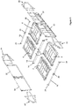
- FIG. 1 there can be seen a schematic exploded view of components of a crate in accordance with the present invention.
- base elements 2,4,6,8 are provided. These may be known base elements for collapsible containers such as that described in GB 2 445 878 B , provided with side portions having openings that allow entry of tines of a fork lift vehicle to enable lifting of such base elements.
- a centre beam 10 is provided between the front and rear sections of the base.
- the front and rear sections are connected to the centre beam 10 in any suitable manner.
- the centre beam 10 is provided with centrally located fixtures 12 for connecting the centre beam to the respective base sections.
- the ends 14 of the centre beam 10 may also be provided with connecting elements to enable the ends of the centre beam to be secured to the adjacent base elements.
- End beams 16,18 are provided to the front and rear of the base secured in any suitable manner to the respective ends of the base elements 2,4,6,8 to complete the base.
- the end beams 16,18 are each provided with respective centrally located fixtures 20,22 for connecting the end beams 16,18 to the respective base sections.
- the ends 14 of each end beam 16,18 may also be provided with connecting elements 24,26 to enable the ends 14 of each end beam 16,18 to be secured to the adjacent base elements.
- the base constructed in this manner can be seen to have left and right hand sides (formed by the base elements 2,4 and 6,8 respectively) and front and rear ends.
- Left and right hand side walls are provided for pivoting engagement with the respective left and right hand sides of the base.
- the left and right hand side walls are essentially identical so only one will be described. It will be understood that the features of one side wall are replicated on the other and like reference numerals are used in the Figures to reflect like parts.
- Each side wall comprises a plurality of wall elements.
- each side wall comprises two wall elements 30,32.
- Each wall element is sized to correspond to the length of a base element.
- a lower edge of the wall element is adapted to engage with an outer edge of a respective base element to pivot with respect to said base element.
- the wall element may be adapted to be releasably connected to the base element to allow for full disassembly but as will be described, this is not essential.
- Each wall element 30,32 is constructed with end posts connected at their lower ends by a connecting beam.
- the lower edges of the each wall element are provided with suitable engagement means to engage with receiving means provided at the outer edge of the respective base element.
- Such engagement means are provided at the lower ends of the posts with the receiving means provided at the corners of the base element.
- An upper end of each end post is conveniently provided with an upwardly extending projection.
- a connecting element 34 may be used to secure the upwardly extending projections of adjacent wall elements 30,32 together (shown most clearly in Figures 3 , 4 and 5 ).
- Each side wall is provided at a front end and a rear end with a pivoting frame member 40,42,44,46. While there are differences between the front and rear pivoting frame members, they share certain common features and similar reference numerals will be used to refer to similar parts in the following description.
- Each pivoting frame member 40,42,44,46 comprises a first leaf and a second leaf.
- a first end of the first leaf is connected to an end of the respective side wall element.
- the first leaf is located in a fixed position with respect to the side wall element.
- a second end of the first leaf is pivotally connected to a first end of the second leaf.
- a second end of the second leaf on one side of the crate is adapted to be moved adjacent to a second end of the second leaf on the opposite side of the crate as will be described below.
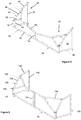
- Figure 2 shows an assembled crate in a collapsed configuration. As may be seen the collapsed crate occupies comparatively little volume.
- the side walls are folded down against the adjacent base elements.
- the pivoting frame members are arranged such that the second leaf is folded back against the first leaf element, such that a portion of the second leaf element rests against an adjacent wall element and the first leaf element extends outwardly as an extension of the adjacent side element.
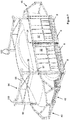
- Figure 3 shows an assembled crate in an open configuration.
- the side walls have been moved, for example by pivoting, into an upright position.
- the side walls are conveniently provided with means to lock the side walls into this position.
- the walls may be connected by a lift and pivot mechanism such as that disclosed in GB 2 445 878 B .
- the pivoting frame members remain in the same relative position to the side walls as in the collapsed configuration.
- each second leaf is rotated through a 270 degree angle such that the second end of one leaf is adjacent the second end of the second leaf.
- the adjacent second ends may additionally be releasably secured together by any suitable means.
- each pivoting frame member is provided with a bracing member.
- the bracing member releaseably retains the first and second leaves of the pivoting frame member in the closed configuration position relative to one another.
- a first end of the bracing member is carried on the second leaf and is pivotally connected thereto.
- a second end of the bracing member is adapted to be releaseably secured to the first leaf.
- the first end of the first leaf 50 comprises a first upright 52, sized to correspond to the height of the wall element to which it will be secured.
- the second end of the first leaf comprises a shorter upright 54. Lower ends of each upright are connected by a horizontal beam 56.
- a beam having first and second angled elements 58,60 connects upper ends of the first and second uprights 52,54.
- the first end of the second leaf 70 comprises an upright 72 corresponding in height to upright 54 forming the second end of the first leaf 50.
- Upright 72 is pivotally connected to upright 54 to allow relative rotation of at least 270 degrees.
- the uprights are linked together to allow such relative rotation with an upper link 90 being shown.
- the second end of the second leaf comprises an upright 74 of similar height to that of the first end of the second leaf.
- Lower ends of each upright are connected by a horizontal beam 76.
- a beam having first and second angled elements 78,80 connects upper ends of the first and second uprights 72,74.
- the angled elements connecting the upper ends of the second end of the first leaf and the first end of the second leaf are of similar length and extend from their respective uprights at similar angles.
- a bracing member 92 is provided connected pivotally at a first end to one of the first and second leaves 50,70 and provided at a second end with releasable means for securing the second end of the bracing member to the other of the first and second leaves 50,70.
- the bracing member 92 is carried on the second leaf secured at the bend between the first and second angled elements 78,80.
- first and second angled elements 158,160 have different relative arrangements in that the angled element 160 connected to the upper end of the upright 152 at the first end of the first leaf is substantially horizontal, and similarly in the case of the second leaf, the angled element 180 connected to the upper end of the upright 174 at the second end of the second leaf is also substantially horizontal. Nevertheless, the bracing member 192 and the respective adjacent angled elements 158,178 of the first and second elements form a triangle creating a robust structure fixing the second leaf in position relative to the first leaf (and so the walls and to the remainder of the crate).
- the crate may additionally be provided with a plurality of lateral frame members 94 for use as illustrated in Figure 7 . These are secured to the upwardly extending projections at the front and rear ends of the crate.
- Each lateral frame member 94 comprises first and second uprights 95,96.
- Each upright 95,96 is adapted to engage with the upwardly extending projections of the end posts to the front and rear of the side walls.
- Additional engagement means 97 may be provided at the lower ends of each upright 95,96 to engage with an upper edge of a respective wall element to secure the upright 95,96 in relation to the respective wall element.
- the uprights 95,96 are held at a suitable distance from one another by a suitably robust transverse structure 98 connecting the uprights.
- the transverse structure 98 is provided between the upper ends of the uprights 95,96.
- Each upright 95,96 is further provided at an upper end thereof with a planar region 100 bounded on two sides by walls 102. It can be seen that the walls 102 are located on the planar region along the sides of the planar region 100 corresponding to the ends and sides of the crate.
- the lateral frame members 94 are used when it is desired to stack a crate in accordance with the present invention on top of another similar crate.
- the lateral frame members 94 are secured into position on a first crate following loading of a motor vehicle within the crate.
- a second loaded crate is then raised, for example using a fork lift or other apparatus readily available in a loading bay, to a height above the first crate, moved and then located above the first crate and finally lowered into position onto the first crate such that the corners of the base of the second crate are located on the planar regions 100 of the lateral frame members 94 within the walls 102 of the planar regions 100.
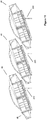
- multiple crates according to the present invention can be stacked one on top of another allowing for efficient use of space within a shipping container or other loading area (see for example Figure 8 ).
- Such crates may be unstacked in the reverse manner when it is desired to remove the motor vehicle from the crate.
- the bracing members 92,192 With the base of the crate on a driving surface, the bracing members 92,192 are released allowing the pivoting frame members 40,42,44,46 to be returned to the open configuration, such that the motor vehicle can be driven from the base of the crate.
- a container is a 40 feet (12.2 m) in length and a car in a crate according the present invention measures 12 feet (3.7m)
- three such crates will not fit end to end within such a container, and 2 crates will leave significant unfilled space in such a container.
- three loaded crates may be fitted into a loaded container.
- Such containers have a maximum height of 9.6 feet (2.9 m)
- the longitudinal footprint is reduced to only 11 feet (3.4m) such that three such crates will fit in a 40 foot (12.2 m) container, with a more efficient use of the space within the container.
- a user will also understand that it will be possible to use crates of different size to accommodate different length of motor vehicle. A user will also understand that it is not necessary too use crates of the same size in a single container, for example there may be mix of crates of various sizes, some inclined, others not, in order to make optimum use of the space available within a container of a particular size.
- a suitable support means 200 is shown in most detail in Figures 9 and 10 .
- Figure 9 two such support means are shown to the rear of a crate. No other support means are shown for reasons of clarity.
- Each support means is secured to an underside of a base element.
- each support means comprises a retaining portion 202, a support member 204 and an abutment 206.
- the retaining portion is formed as an elongate substantially U-shaped member having depending side members 208,210 joined by a connecting web 209.
- An end wall 222 located at or towards one end retaining portion extends across the retaining portion 202.
- the end wall 222 is provided to one side with a through opening (not shown).
- the retaining portion 202 is secured to the base element in any suitable manner, for example along one of the depending side members 208,210 and/or the connecting portion 209.
- the free depending side member 208 is provided at a first end with a through opening 212.
- the second end of the retaining portion 202 is provided with a bolt, pin or similar extending between the depending side members 208,210 to provide a pivot pin 214 upon which the support member 204 is secured for pivoting movement.
- the support member 204 comprises a tubular member, in the illustrated embodiment a tube of rectangular, preferably square section.
- the support member 204 is provided on an end remote from the pivot pin with an inwardly directed foot 220 for engaging with a floor surface when the support is in a deployed position.
- the support member is provided on at least one side with a through opening 216.
- the support member 204 is further provided with a through opening disposed normally to the pivot pin 214.
- the abutment member 206 extends from one side of the support member 204 and terminates prior to the portion of the support member204 engaging with the pivot pin 214.
- the abutment member 206 preferably comprises another tubular member of rectangular, preferably square section, a first side of which is permanently secured in any suitable manner with the support member 204.
- the support member 204 and the abutment member 206 are seated within the retaining portion 202.
- the openings 212,204 in the depending wall 208 of the retaining portion 202 and the support member 204 are aligned.
- a retaining pin or bolt 224 extends through these openings 212,216 to keep the support member 204 and the abutment member 206 in the retracted position.
- the retaining pin 224 can be removed allowing the support member 204 and the abutment member 206 to pivot with respect to the base element toward the deployed position.
- the support member 204 is slid along the pivot pin from one side of the retaining portion 202 to the other, such that an upper end of the abutment member 206 is beneath the underside of the base element.
- the retaining pin 224 may then introduced into the upper opening in the upper end of the support member 204 and into the opening in the end plate 222 of the retaining portion 202 to locate the support member 202 in position.
- the crate is further lowered until the foot 220 of the support member 204 comes into contact with the floor.
- the crate is lifted to allow the support member 204 to be returned to the retracted position. This is achieved by removing the retaining pin 224 from the support member 204 and the end wall 222 of the retaining portion 202, sliding the support member 204 back along the pivot pin 214 to allow the support member 204 and abutment member 206 to be pivoted to the retracted position within the retaining portion 202 and the retaining pin 224 inserted once again through the support member 204 and the side wall 208 of the retaining portion 202 to hold the support member 204 (and the abutment member 206) adjacent the underside of the crate.
- the crate can then be lowered to a horizontal position and subsequently opened to allow the motor vehicle to be removed.
Landscapes
- Engineering & Computer Science (AREA)
- Mechanical Engineering (AREA)
- Pallets (AREA)
- Rigid Containers With Two Or More Constituent Elements (AREA)
Claims (11)
- Kiste für den Transport von Kraftfahrzeugen, passend zum Einlegen in einen Versandcontainer,
wobei die Kiste eine rechteckige Basis umfasst, welche linke und rechte Seite und vorderes und hinteres Ende besitzt, linke und rechte Seitenwand, die entlang der jeweiligen Seite der Basis verbunden sind, wobei jede Seitenwand an einem vorderen und einem hinteren Ende ein schwenkbares Rahmenglied (40, 42, 44, 46) trägt,
dadurch gekennzeichnet, dass:jedes Rahmenglied ein erstes Blatt (50) und ein zweites Blatt (70) umfasst, wobei ein erstes Ende des ersten Blattes (50) mit einem Ende der Seitenwand verbunden ist, und ein zweites Ende mit einem ersten Ende des zweiten Blattes (70) verbunden ist;die Kiste zudem eines oder mehrere ausklappbare Trägerglieder (204) umfasst, die zwischen einer eingezogenen und einer ausgeklappten Position beweglich sind; unddas eine oder die mehreren Trägerglied(er) (204) in der ausgeklappten Position zum Halten der Kiste in einem Winkel gesichert werden kann/können. - Kiste nach Anspruch 1, bei welcher die Seitenwände schwenkbar mit der Basis verbunden sind.
- Kiste nach Anspruch 1, bei welcher die Seitenwände lösbar mit der Basis verbunden sind.
- Kiste nach einem der Ansprüche 1 bis 3, bei welcher die Basis eine Vielzahl von Elementen (2, 4, 6, 8), einen Mittelträger (10) zwischen zwei der Basiselemente und Seitenträger besitzt, die an den vorderem und hinterem Ende der Basis angeordnet sind.
- Kiste nach Anspruch 4, bei welcher jede Seitenwand zwei Wandelemente (30, 32) umfasst, welche jeweils mit einer Seite des jeweiligen Basiselements (2, 4, 6, 8) verbunden sind.
- Kiste nach einem der Ansprüche 1 bis 5, bei welcher jedes zweite Ende eines jeden zweiten Blattes (70) geeignet ist, lösbar mit einem gegenüberliegenden zweiten Ende des gegenüberliegenden zweiten Blattes (70) verbunden zu werden.
- Kiste nach einem der Ansprüche 1 bis 6, bei welcher jedes schwenkbare Rahmenglied (40, 42, 44, 46) mit einem Stützglied (92) versehen ist.
- Kiste nach Anspruch 7, bei welcher ein erstes Ende des Stützgliedes (92) schwenkbar mit dem zweiten Blatt (70) verbunden ist und ein zweites Ende geeignet ist, lösbar am ersten Blatt (50) gesichert zu werden.
- Kiste nach einem der Ansprüche 1 bis 8, bei welcher die Kiste zusätzlich eine Vielzahl von Rahmengliedern (94) zur Sicherung an und quer zu den vorderen und hinteren Enden der Kiste beinhaltet.
- Kiste nach Anspruch 9, bei welcher jedes der Rahmenglieder (94) mit einem Aufnahmemittel zur Aufnahme einer Basis einer weiteren Kiste versehen ist, wodurch eine Kiste über der anderen gestapelt werden kann.
- Kiste nach einem der Ansprüche 1 bis 10, bei welcher das eine oder die mehreren Trägerglied(er) (204) so angeordnet ist/sind, dass eine Längsgrundfläche der Kiste in der ausgeklappten Position reduziert ist.
Applications Claiming Priority (1)
| Application Number | Priority Date | Filing Date | Title |
|---|---|---|---|
| PCT/IB2013/055031 WO2014203037A1 (en) | 2013-06-19 | 2013-06-19 | Crates |
Publications (2)
| Publication Number | Publication Date |
|---|---|
| EP3010837A1 EP3010837A1 (de) | 2016-04-27 |
| EP3010837B1 true EP3010837B1 (de) | 2017-10-25 |
Family
ID=49766132
Family Applications (1)
| Application Number | Title | Priority Date | Filing Date |
|---|---|---|---|
| EP13805959.7A Not-in-force EP3010837B1 (de) | 2013-06-19 | 2013-06-19 | Kisten für den transport von kraftfahrzeugen |
Country Status (4)
| Country | Link |
|---|---|
| EP (1) | EP3010837B1 (de) |
| ES (1) | ES2655192T3 (de) |
| SG (1) | SG11201600305YA (de) |
| WO (1) | WO2014203037A1 (de) |
Family Cites Families (9)
| Publication number | Priority date | Publication date | Assignee | Title |
|---|---|---|---|---|
| GB1258284A (de) * | 1968-10-02 | 1971-12-30 | ||
| FR2186393B1 (de) * | 1972-05-31 | 1976-10-29 | Reunis Sa Ateliers | |
| JPH02191180A (ja) * | 1988-12-29 | 1990-07-27 | Shigenobu Furukawa | コンテナ |
| GB2293160B (en) * | 1994-09-15 | 1997-12-10 | Lin Pac Mouldings | A frame and a container having upstanding side walls provided by the frame |
| GB0108996D0 (en) * | 2001-04-10 | 2001-05-30 | Clive Smith Martin | Collapsible flatrack with end extensions |
| GB0624217D0 (en) | 2006-12-04 | 2007-01-10 | Cronos Containers Ltd | Transporting vehicles |
| GB2445878B (en) | 2008-02-13 | 2009-05-20 | Goodpack Ltd | Crates |
| AU2010203295B2 (en) * | 2009-07-31 | 2016-07-14 | Jamie Andrew Treacy | Transportable Support Structure |
| SE535553C2 (sv) | 2011-04-08 | 2012-09-18 | Kyrkbyns Ind Ab | Anordning för transport och förvaring av personbilar |
-
2013
- 2013-06-19 EP EP13805959.7A patent/EP3010837B1/de not_active Not-in-force
- 2013-06-19 SG SG11201600305YA patent/SG11201600305YA/en unknown
- 2013-06-19 WO PCT/IB2013/055031 patent/WO2014203037A1/en active Application Filing
- 2013-06-19 ES ES13805959.7T patent/ES2655192T3/es active Active
Non-Patent Citations (1)
| Title |
|---|
| None * |
Also Published As
| Publication number | Publication date |
|---|---|
| WO2014203037A1 (en) | 2014-12-24 |
| SG11201600305YA (en) | 2016-02-26 |
| EP3010837A1 (de) | 2016-04-27 |
| ES2655192T3 (es) | 2018-02-19 |
Similar Documents
| Publication | Publication Date | Title |
|---|---|---|
| US9394100B2 (en) | Pallet container | |
| US5253763A (en) | Collapsible container | |
| US8327775B2 (en) | Transport pallet | |
| US6513442B1 (en) | Foldable container for vehicles | |
| US10632894B2 (en) | Two-level pallet for stackable loading | |
| JP5553453B2 (ja) | 荷の輸送 | |
| US4662532A (en) | Foldable container | |
| US8210374B2 (en) | Rackable collapsible stackable unit | |
| US8376168B2 (en) | Collapsible container | |
| JP5779093B2 (ja) | 折り畳み式コンテナおよび折り畳まれたコンテナを輸送する方法 | |
| JP2013518788A (ja) | コンテナ処理装置、そのようなものの利用法、および積み下ろし時の方法 | |
| KR20070064890A (ko) | 차량 선적용 콘테이너 | |
| KR20210126139A (ko) | 화물 유닛 | |
| EP3010837B1 (de) | Kisten für den transport von kraftfahrzeugen | |
| WO2007129986A1 (en) | Collapsible container | |
| US20130206620A1 (en) | Collapsible Garment Stillage | |
| EP2357142A1 (de) | Käfigstruktur zum Gütertransport | |
| CA2682416A1 (en) | Open-deck freight container | |
| WO2003055755A2 (en) | Crates | |
| WO1999033711A1 (en) | Collapsible container | |
| JPH0126589Y2 (de) | ||
| KR101375805B1 (ko) | 접이식 컨테이너 | |
| JP2005298003A (ja) | 運搬用パレットの荷崩れ防止装置 |
Legal Events
| Date | Code | Title | Description |
|---|---|---|---|
| PUAI | Public reference made under article 153(3) epc to a published international application that has entered the european phase |
Free format text: ORIGINAL CODE: 0009012 |
|
| 17P | Request for examination filed |
Effective date: 20160118 |
|
| AK | Designated contracting states |
Kind code of ref document: A1 Designated state(s): AL AT BE BG CH CY CZ DE DK EE ES FI FR GB GR HR HU IE IS IT LI LT LU LV MC MK MT NL NO PL PT RO RS SE SI SK SM TR |
|
| AX | Request for extension of the european patent |
Extension state: BA ME |
|
| DAX | Request for extension of the european patent (deleted) | ||
| GRAP | Despatch of communication of intention to grant a patent |
Free format text: ORIGINAL CODE: EPIDOSNIGR1 |
|
| STAA | Information on the status of an ep patent application or granted ep patent |
Free format text: STATUS: GRANT OF PATENT IS INTENDED |
|
| INTG | Intention to grant announced |
Effective date: 20170316 |
|
| GRAJ | Information related to disapproval of communication of intention to grant by the applicant or resumption of examination proceedings by the epo deleted |
Free format text: ORIGINAL CODE: EPIDOSDIGR1 |
|
| GRAL | Information related to payment of fee for publishing/printing deleted |
Free format text: ORIGINAL CODE: EPIDOSDIGR3 |
|
| GRAS | Grant fee paid |
Free format text: ORIGINAL CODE: EPIDOSNIGR3 |
|
| STAA | Information on the status of an ep patent application or granted ep patent |
Free format text: STATUS: REQUEST FOR EXAMINATION WAS MADE |
|
| INTC | Intention to grant announced (deleted) | ||
| GRAR | Information related to intention to grant a patent recorded |
Free format text: ORIGINAL CODE: EPIDOSNIGR71 |
|
| STAA | Information on the status of an ep patent application or granted ep patent |
Free format text: STATUS: GRANT OF PATENT IS INTENDED |
|
| GRAA | (expected) grant |
Free format text: ORIGINAL CODE: 0009210 |
|
| STAA | Information on the status of an ep patent application or granted ep patent |
Free format text: STATUS: THE PATENT HAS BEEN GRANTED |
|
| INTG | Intention to grant announced |
Effective date: 20170913 |
|
| AK | Designated contracting states |
Kind code of ref document: B1 Designated state(s): AL AT BE BG CH CY CZ DE DK EE ES FI FR GB GR HR HU IE IS IT LI LT LU LV MC MK MT NL NO PL PT RO RS SE SI SK SM TR |
|
| REG | Reference to a national code |
Ref country code: GB Ref legal event code: FG4D |
|
| REG | Reference to a national code |
Ref country code: CH Ref legal event code: EP |
|
| REG | Reference to a national code |
Ref country code: AT Ref legal event code: REF Ref document number: 939685 Country of ref document: AT Kind code of ref document: T Effective date: 20171115 |
|
| REG | Reference to a national code |
Ref country code: IE Ref legal event code: FG4D |
|
| REG | Reference to a national code |
Ref country code: DE Ref legal event code: R096 Ref document number: 602013028493 Country of ref document: DE |
|
| REG | Reference to a national code |
Ref country code: NL Ref legal event code: FP |
|
| REG | Reference to a national code |
Ref country code: ES Ref legal event code: FG2A Ref document number: 2655192 Country of ref document: ES Kind code of ref document: T3 Effective date: 20180219 |
|
| REG | Reference to a national code |
Ref country code: LT Ref legal event code: MG4D |
|
| REG | Reference to a national code |
Ref country code: AT Ref legal event code: MK05 Ref document number: 939685 Country of ref document: AT Kind code of ref document: T Effective date: 20171025 |
|
| PG25 | Lapsed in a contracting state [announced via postgrant information from national office to epo] |
Ref country code: FI Free format text: LAPSE BECAUSE OF FAILURE TO SUBMIT A TRANSLATION OF THE DESCRIPTION OR TO PAY THE FEE WITHIN THE PRESCRIBED TIME-LIMIT Effective date: 20171025 Ref country code: SE Free format text: LAPSE BECAUSE OF FAILURE TO SUBMIT A TRANSLATION OF THE DESCRIPTION OR TO PAY THE FEE WITHIN THE PRESCRIBED TIME-LIMIT Effective date: 20171025 Ref country code: LT Free format text: LAPSE BECAUSE OF FAILURE TO SUBMIT A TRANSLATION OF THE DESCRIPTION OR TO PAY THE FEE WITHIN THE PRESCRIBED TIME-LIMIT Effective date: 20171025 Ref country code: NO Free format text: LAPSE BECAUSE OF FAILURE TO SUBMIT A TRANSLATION OF THE DESCRIPTION OR TO PAY THE FEE WITHIN THE PRESCRIBED TIME-LIMIT Effective date: 20180125 |
|
| PG25 | Lapsed in a contracting state [announced via postgrant information from national office to epo] |
Ref country code: RS Free format text: LAPSE BECAUSE OF FAILURE TO SUBMIT A TRANSLATION OF THE DESCRIPTION OR TO PAY THE FEE WITHIN THE PRESCRIBED TIME-LIMIT Effective date: 20171025 Ref country code: BG Free format text: LAPSE BECAUSE OF FAILURE TO SUBMIT A TRANSLATION OF THE DESCRIPTION OR TO PAY THE FEE WITHIN THE PRESCRIBED TIME-LIMIT Effective date: 20180125 Ref country code: IS Free format text: LAPSE BECAUSE OF FAILURE TO SUBMIT A TRANSLATION OF THE DESCRIPTION OR TO PAY THE FEE WITHIN THE PRESCRIBED TIME-LIMIT Effective date: 20180225 Ref country code: AT Free format text: LAPSE BECAUSE OF FAILURE TO SUBMIT A TRANSLATION OF THE DESCRIPTION OR TO PAY THE FEE WITHIN THE PRESCRIBED TIME-LIMIT Effective date: 20171025 Ref country code: GR Free format text: LAPSE BECAUSE OF FAILURE TO SUBMIT A TRANSLATION OF THE DESCRIPTION OR TO PAY THE FEE WITHIN THE PRESCRIBED TIME-LIMIT Effective date: 20180126 Ref country code: HR Free format text: LAPSE BECAUSE OF FAILURE TO SUBMIT A TRANSLATION OF THE DESCRIPTION OR TO PAY THE FEE WITHIN THE PRESCRIBED TIME-LIMIT Effective date: 20171025 Ref country code: LV Free format text: LAPSE BECAUSE OF FAILURE TO SUBMIT A TRANSLATION OF THE DESCRIPTION OR TO PAY THE FEE WITHIN THE PRESCRIBED TIME-LIMIT Effective date: 20171025 |
|
| REG | Reference to a national code |
Ref country code: FR Ref legal event code: PLFP Year of fee payment: 6 |
|
| REG | Reference to a national code |
Ref country code: DE Ref legal event code: R097 Ref document number: 602013028493 Country of ref document: DE |
|
| PG25 | Lapsed in a contracting state [announced via postgrant information from national office to epo] |
Ref country code: SK Free format text: LAPSE BECAUSE OF FAILURE TO SUBMIT A TRANSLATION OF THE DESCRIPTION OR TO PAY THE FEE WITHIN THE PRESCRIBED TIME-LIMIT Effective date: 20171025 Ref country code: CZ Free format text: LAPSE BECAUSE OF FAILURE TO SUBMIT A TRANSLATION OF THE DESCRIPTION OR TO PAY THE FEE WITHIN THE PRESCRIBED TIME-LIMIT Effective date: 20171025 Ref country code: DK Free format text: LAPSE BECAUSE OF FAILURE TO SUBMIT A TRANSLATION OF THE DESCRIPTION OR TO PAY THE FEE WITHIN THE PRESCRIBED TIME-LIMIT Effective date: 20171025 Ref country code: CY Free format text: LAPSE BECAUSE OF FAILURE TO SUBMIT A TRANSLATION OF THE DESCRIPTION OR TO PAY THE FEE WITHIN THE PRESCRIBED TIME-LIMIT Effective date: 20171025 Ref country code: EE Free format text: LAPSE BECAUSE OF FAILURE TO SUBMIT A TRANSLATION OF THE DESCRIPTION OR TO PAY THE FEE WITHIN THE PRESCRIBED TIME-LIMIT Effective date: 20171025 |
|
| PG25 | Lapsed in a contracting state [announced via postgrant information from national office to epo] |
Ref country code: PL Free format text: LAPSE BECAUSE OF FAILURE TO SUBMIT A TRANSLATION OF THE DESCRIPTION OR TO PAY THE FEE WITHIN THE PRESCRIBED TIME-LIMIT Effective date: 20171025 Ref country code: RO Free format text: LAPSE BECAUSE OF FAILURE TO SUBMIT A TRANSLATION OF THE DESCRIPTION OR TO PAY THE FEE WITHIN THE PRESCRIBED TIME-LIMIT Effective date: 20171025 Ref country code: SM Free format text: LAPSE BECAUSE OF FAILURE TO SUBMIT A TRANSLATION OF THE DESCRIPTION OR TO PAY THE FEE WITHIN THE PRESCRIBED TIME-LIMIT Effective date: 20171025 |
|
| PLBE | No opposition filed within time limit |
Free format text: ORIGINAL CODE: 0009261 |
|
| STAA | Information on the status of an ep patent application or granted ep patent |
Free format text: STATUS: NO OPPOSITION FILED WITHIN TIME LIMIT |
|
| 26N | No opposition filed |
Effective date: 20180726 |
|
| PG25 | Lapsed in a contracting state [announced via postgrant information from national office to epo] |
Ref country code: SI Free format text: LAPSE BECAUSE OF FAILURE TO SUBMIT A TRANSLATION OF THE DESCRIPTION OR TO PAY THE FEE WITHIN THE PRESCRIBED TIME-LIMIT Effective date: 20171025 |
|
| REG | Reference to a national code |
Ref country code: CH Ref legal event code: PL |
|
| REG | Reference to a national code |
Ref country code: BE Ref legal event code: MM Effective date: 20180630 |
|
| REG | Reference to a national code |
Ref country code: IE Ref legal event code: MM4A |
|
| PG25 | Lapsed in a contracting state [announced via postgrant information from national office to epo] |
Ref country code: MC Free format text: LAPSE BECAUSE OF FAILURE TO SUBMIT A TRANSLATION OF THE DESCRIPTION OR TO PAY THE FEE WITHIN THE PRESCRIBED TIME-LIMIT Effective date: 20171025 Ref country code: LU Free format text: LAPSE BECAUSE OF NON-PAYMENT OF DUE FEES Effective date: 20180619 |
|
| PG25 | Lapsed in a contracting state [announced via postgrant information from national office to epo] |
Ref country code: IE Free format text: LAPSE BECAUSE OF NON-PAYMENT OF DUE FEES Effective date: 20180619 Ref country code: CH Free format text: LAPSE BECAUSE OF NON-PAYMENT OF DUE FEES Effective date: 20180630 Ref country code: LI Free format text: LAPSE BECAUSE OF NON-PAYMENT OF DUE FEES Effective date: 20180630 |
|
| PG25 | Lapsed in a contracting state [announced via postgrant information from national office to epo] |
Ref country code: BE Free format text: LAPSE BECAUSE OF NON-PAYMENT OF DUE FEES Effective date: 20180630 |
|
| PGFP | Annual fee paid to national office [announced via postgrant information from national office to epo] |
Ref country code: NL Payment date: 20190626 Year of fee payment: 7 Ref country code: IT Payment date: 20190620 Year of fee payment: 7 Ref country code: DE Payment date: 20190618 Year of fee payment: 7 |
|
| PGFP | Annual fee paid to national office [announced via postgrant information from national office to epo] |
Ref country code: FR Payment date: 20190620 Year of fee payment: 7 |
|
| PGFP | Annual fee paid to national office [announced via postgrant information from national office to epo] |
Ref country code: GB Payment date: 20190619 Year of fee payment: 7 Ref country code: ES Payment date: 20190701 Year of fee payment: 7 |
|
| PG25 | Lapsed in a contracting state [announced via postgrant information from national office to epo] |
Ref country code: MT Free format text: LAPSE BECAUSE OF NON-PAYMENT OF DUE FEES Effective date: 20180619 |
|
| REG | Reference to a national code |
Ref country code: DE Ref legal event code: R081 Ref document number: 602013028493 Country of ref document: DE Owner name: GOODPACK IBC (SINGAPORE) PTE. LTD., SG Free format text: FORMER OWNER: LAM, DAVID CHOON SEN, SINGAPORE, SG |
|
| REG | Reference to a national code |
Ref country code: NL Ref legal event code: PD Owner name: GOODPACK IBC (SINGAPORE) PTE. LTD.; SG Free format text: DETAILS ASSIGNMENT: CHANGE OF OWNER(S), ASSIGNMENT; FORMER OWNER NAME: LAM, DAVID CHOON SEN Effective date: 20200306 |
|
| PG25 | Lapsed in a contracting state [announced via postgrant information from national office to epo] |
Ref country code: TR Free format text: LAPSE BECAUSE OF FAILURE TO SUBMIT A TRANSLATION OF THE DESCRIPTION OR TO PAY THE FEE WITHIN THE PRESCRIBED TIME-LIMIT Effective date: 20171025 |
|
| REG | Reference to a national code |
Ref country code: ES Ref legal event code: PC2A Owner name: GOODPACK IBC (SINGAPORE) PTE. LTD Effective date: 20200330 |
|
| REG | Reference to a national code |
Ref country code: GB Ref legal event code: 732E Free format text: REGISTERED BETWEEN 20200312 AND 20200318 |
|
| PG25 | Lapsed in a contracting state [announced via postgrant information from national office to epo] |
Ref country code: PT Free format text: LAPSE BECAUSE OF FAILURE TO SUBMIT A TRANSLATION OF THE DESCRIPTION OR TO PAY THE FEE WITHIN THE PRESCRIBED TIME-LIMIT Effective date: 20171025 |
|
| PG25 | Lapsed in a contracting state [announced via postgrant information from national office to epo] |
Ref country code: HU Free format text: LAPSE BECAUSE OF FAILURE TO SUBMIT A TRANSLATION OF THE DESCRIPTION OR TO PAY THE FEE WITHIN THE PRESCRIBED TIME-LIMIT; INVALID AB INITIO Effective date: 20130619 Ref country code: MK Free format text: LAPSE BECAUSE OF NON-PAYMENT OF DUE FEES Effective date: 20171025 |
|
| PG25 | Lapsed in a contracting state [announced via postgrant information from national office to epo] |
Ref country code: AL Free format text: LAPSE BECAUSE OF FAILURE TO SUBMIT A TRANSLATION OF THE DESCRIPTION OR TO PAY THE FEE WITHIN THE PRESCRIBED TIME-LIMIT Effective date: 20171025 |
|
| REG | Reference to a national code |
Ref country code: DE Ref legal event code: R119 Ref document number: 602013028493 Country of ref document: DE |
|
| REG | Reference to a national code |
Ref country code: NL Ref legal event code: MM Effective date: 20200701 |
|
| GBPC | Gb: european patent ceased through non-payment of renewal fee |
Effective date: 20200619 |
|
| PG25 | Lapsed in a contracting state [announced via postgrant information from national office to epo] |
Ref country code: GB Free format text: LAPSE BECAUSE OF NON-PAYMENT OF DUE FEES Effective date: 20200619 Ref country code: FR Free format text: LAPSE BECAUSE OF NON-PAYMENT OF DUE FEES Effective date: 20200630 Ref country code: NL Free format text: LAPSE BECAUSE OF NON-PAYMENT OF DUE FEES Effective date: 20200701 |
|
| PG25 | Lapsed in a contracting state [announced via postgrant information from national office to epo] |
Ref country code: DE Free format text: LAPSE BECAUSE OF NON-PAYMENT OF DUE FEES Effective date: 20210101 |
|
| PG25 | Lapsed in a contracting state [announced via postgrant information from national office to epo] |
Ref country code: IT Free format text: LAPSE BECAUSE OF NON-PAYMENT OF DUE FEES Effective date: 20200619 |
|
| REG | Reference to a national code |
Ref country code: ES Ref legal event code: FD2A Effective date: 20211103 |
|
| PG25 | Lapsed in a contracting state [announced via postgrant information from national office to epo] |
Ref country code: ES Free format text: LAPSE BECAUSE OF NON-PAYMENT OF DUE FEES Effective date: 20200620 |