EP3010232B1 - Bildcodierungsvorrichtung, bildcodierungsverfahren, bilddecodierungsvorrichtung und bilddecodierungsverfahren - Google Patents
Bildcodierungsvorrichtung, bildcodierungsverfahren, bilddecodierungsvorrichtung und bilddecodierungsverfahren Download PDFInfo
- Publication number
- EP3010232B1 EP3010232B1 EP14810646.1A EP14810646A EP3010232B1 EP 3010232 B1 EP3010232 B1 EP 3010232B1 EP 14810646 A EP14810646 A EP 14810646A EP 3010232 B1 EP3010232 B1 EP 3010232B1
- Authority
- EP
- European Patent Office
- Prior art keywords
- picture
- field
- prediction
- image
- encoding
- Prior art date
- Legal status (The legal status is an assumption and is not a legal conclusion. Google has not performed a legal analysis and makes no representation as to the accuracy of the status listed.)
- Active
Links
Images


Classifications
-
- H—ELECTRICITY
- H04—ELECTRIC COMMUNICATION TECHNIQUE
- H04N—PICTORIAL COMMUNICATION, e.g. TELEVISION
- H04N19/00—Methods or arrangements for coding, decoding, compressing or decompressing digital video signals
- H04N19/50—Methods or arrangements for coding, decoding, compressing or decompressing digital video signals using predictive coding
- H04N19/593—Methods or arrangements for coding, decoding, compressing or decompressing digital video signals using predictive coding involving spatial prediction techniques
-
- H—ELECTRICITY
- H04—ELECTRIC COMMUNICATION TECHNIQUE
- H04N—PICTORIAL COMMUNICATION, e.g. TELEVISION
- H04N19/00—Methods or arrangements for coding, decoding, compressing or decompressing digital video signals
- H04N19/10—Methods or arrangements for coding, decoding, compressing or decompressing digital video signals using adaptive coding
- H04N19/102—Methods or arrangements for coding, decoding, compressing or decompressing digital video signals using adaptive coding characterised by the element, parameter or selection affected or controlled by the adaptive coding
- H04N19/103—Selection of coding mode or of prediction mode
- H04N19/107—Selection of coding mode or of prediction mode between spatial and temporal predictive coding, e.g. picture refresh
-
- H—ELECTRICITY
- H04—ELECTRIC COMMUNICATION TECHNIQUE
- H04N—PICTORIAL COMMUNICATION, e.g. TELEVISION
- H04N19/00—Methods or arrangements for coding, decoding, compressing or decompressing digital video signals
- H04N19/10—Methods or arrangements for coding, decoding, compressing or decompressing digital video signals using adaptive coding
- H04N19/102—Methods or arrangements for coding, decoding, compressing or decompressing digital video signals using adaptive coding characterised by the element, parameter or selection affected or controlled by the adaptive coding
- H04N19/103—Selection of coding mode or of prediction mode
- H04N19/114—Adapting the group of pictures [GOP] structure, e.g. number of B-frames between two anchor frames
-
- H—ELECTRICITY
- H04—ELECTRIC COMMUNICATION TECHNIQUE
- H04N—PICTORIAL COMMUNICATION, e.g. TELEVISION
- H04N19/00—Methods or arrangements for coding, decoding, compressing or decompressing digital video signals
- H04N19/10—Methods or arrangements for coding, decoding, compressing or decompressing digital video signals using adaptive coding
- H04N19/134—Methods or arrangements for coding, decoding, compressing or decompressing digital video signals using adaptive coding characterised by the element, parameter or criterion affecting or controlling the adaptive coding
- H04N19/157—Assigned coding mode, i.e. the coding mode being predefined or preselected to be further used for selection of another element or parameter
- H04N19/159—Prediction type, e.g. intra-frame, inter-frame or bidirectional frame prediction
-
- H—ELECTRICITY
- H04—ELECTRIC COMMUNICATION TECHNIQUE
- H04N—PICTORIAL COMMUNICATION, e.g. TELEVISION
- H04N19/00—Methods or arrangements for coding, decoding, compressing or decompressing digital video signals
- H04N19/10—Methods or arrangements for coding, decoding, compressing or decompressing digital video signals using adaptive coding
- H04N19/134—Methods or arrangements for coding, decoding, compressing or decompressing digital video signals using adaptive coding characterised by the element, parameter or criterion affecting or controlling the adaptive coding
- H04N19/157—Assigned coding mode, i.e. the coding mode being predefined or preselected to be further used for selection of another element or parameter
- H04N19/16—Assigned coding mode, i.e. the coding mode being predefined or preselected to be further used for selection of another element or parameter for a given display mode, e.g. for interlaced or progressive display mode
-
- H—ELECTRICITY
- H04—ELECTRIC COMMUNICATION TECHNIQUE
- H04N—PICTORIAL COMMUNICATION, e.g. TELEVISION
- H04N19/00—Methods or arrangements for coding, decoding, compressing or decompressing digital video signals
- H04N19/10—Methods or arrangements for coding, decoding, compressing or decompressing digital video signals using adaptive coding
- H04N19/169—Methods or arrangements for coding, decoding, compressing or decompressing digital video signals using adaptive coding characterised by the coding unit, i.e. the structural portion or semantic portion of the video signal being the object or the subject of the adaptive coding
- H04N19/17—Methods or arrangements for coding, decoding, compressing or decompressing digital video signals using adaptive coding characterised by the coding unit, i.e. the structural portion or semantic portion of the video signal being the object or the subject of the adaptive coding the unit being an image region, e.g. an object
- H04N19/172—Methods or arrangements for coding, decoding, compressing or decompressing digital video signals using adaptive coding characterised by the coding unit, i.e. the structural portion or semantic portion of the video signal being the object or the subject of the adaptive coding the unit being an image region, e.g. an object the region being a picture, frame or field
-
- H—ELECTRICITY
- H04—ELECTRIC COMMUNICATION TECHNIQUE
- H04N—PICTORIAL COMMUNICATION, e.g. TELEVISION
- H04N19/00—Methods or arrangements for coding, decoding, compressing or decompressing digital video signals
- H04N19/70—Methods or arrangements for coding, decoding, compressing or decompressing digital video signals characterised by syntax aspects related to video coding, e.g. related to compression standards
Definitions
- the present invention relates to an image encoding device for and an image encoding method of performing encoding with a high degree of efficiency, and an image decoding device and an image decoding method.
- an inputted color image is partitioned into largest coding blocks each having a predetermined size, and each largest coding block is further partitioned hierarchically into smaller coding blocks.
- Each coding block is further partitioned into smaller prediction blocks, and an intra-screen prediction and a motion-compensated prediction are performed on each of the prediction blocks to generate a prediction error.
- the prediction error is divided hierarchically into transformation blocks within each coding block, and each of the transform coefficients is entropy-encoded, thereby achieving a high compression ratio.
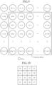
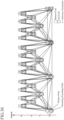
- a gray (shaded) picture having a number of 8 in the display order of Fig. 37 (having a number of 1 in the decoding (encoding)) order is set as a picture which is described in nonpatent reference 1 and can be accessed randomly (Intra Random Access Point (IRAP) picture described in nonpatent reference 1).
- IRAP Intra Random Access Point
- each leading picture must be decoded (encoded) before the trailing pictures.
- a picture whose display order is later than that of the CRA picture can be always decoded correctly by starting the decoding from the CRA picture, and a halfway playback of the encoded sequence can be implemented.
- the leading pictures make it possible to perform a bidirectional prediction also including the CRA picture, and a reduction of the coding efficiency which is caused by the insertion of the picture which can be accessed randomly can be reduced.
- Nonpatent reference 1 B. Bross, W.-J. B. Bross, W.-J. Han, J. -R. Ohm, G. J. Sullivan, Y.-K. Wang and T. Wiegand, "High Efficiency Video Coding (HEVC) text specification draft 10 (for FDIS & Consent)", doc. JCTVC-L1003, Joint Collaborative Team on Video Coding (JCT-VC) of ITU-T SG16 WP3 and ISO/IEC JTC1/SC29/WG11, 12th Meeting, 2013
- HEVC High Efficiency Video Coding
- the conventional image encoding device is constructed as above, in the case of a progressive video in which each frame consists of one picture, by starting the decoding from a specific picture even from some midpoint in an encoded bitstream, a random access which makes it possible to correctly decode pictures after the picture in the display order can be implemented.
- an interlaced video in which each frame consists of two fields: a top field and a bottom field
- there is a case of performing the encoding with the field pair configuration being provided as a reference configuration each frame which consists of two fields being taken into consideration in the field pair configuration, while setting each of these fields as a picture which is a coding unit.
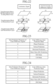
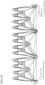
- An example of the field pair configuration using a bidirectional prediction is shown in Fig.
- the decoding order must be the one in which immediately after the top field having a number of 32 in the display order is decoded, the bottom field having a number of 33 in the display order which is a trailing picture is decoded and, after that, leading pictures are decoded.
- the reference configuration is changed to the one in which each leading picture does not refer to the bottom field having a number of 33 in the display order while it is necessary to modify the configuration in such a way that the bottom field having a number of 33 in the display order is decoded after the leading pictures are decoded, and define the bottom field having a number of 33 in the display order as a CRA picture.
- a problem with the former case is therefore that because the reference picture of each leading picture is limited as compared with the reference configuration of Fig. 33 , the prediction efficiency degrades.
- the present invention is made in order to solve the above-mentioned problems, and it is therefore an object of the present invention to provide an image encoding device, an image encoding method, an image decoding device, and an image decoding method that make it possible to generate and encode an encoded bitstream which can be played back at all times from the same field irrespective of the decoding start position of the encoded bitstream also in the field pair encoding of an interlaced video.
- an image encoding device that encodes each field as a picture, each frame consisting of two fields: a first field and a second field
- the image encoding device including: an encoder that encodes a first field of a specific frame as an intra picture which is predicted by using only an intra prediction, and that encodes the first field of the above-described specific frame, the second field of the above-described specific frame, a picture whose encoding order is later than that of the first field of the above-described specific frame later and whose display order is earlier than that of the first field, and another picture whose encoding order and also display order are later than those of the first field of the above-described specific frame in order of those pictures; and a multiplexer that multiplexes information showing that the first field of the above-described specific frame is a picture, in a bitstream, at which decoding can be started into the above-described bitstream.
- the image encoding device is configured in such a way as to generate an encoded bitstream which can be correctly played back from the same field at all times irrespective of the decoding start position of the encoded bitstream also in the field pair encoding of an interlaced video
- a display device that displays the decoded image has only to be configured in such a way as to always display the same field first irrespective of the decoding start position of the encoded bitstream also in the field pair encoding of an interlaced video, and there is provided an advantage of being able to easily perform the display process.
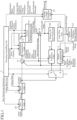
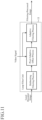
- FIG. 1 is a block diagram showing an image encoding device in accordance with example useful for understanding the present invention.
- the gradation of each pixel can be an 8-bit, 10-bit, or 12-bit one.
- the input signal can be a still image signal, instead of a video signal, because the still image signal can be assumed to be a video signal which consists of only a single frame.
- the inputted video signal is assumed to be, unless otherwise specified, a signal having a YUV4:2:0 format in which the two color difference components U and V are subsampled by a factor of two both in the vertical and horizontal directions with respect to the luminance component Y, a signal having a YUV4:2:2 format in which the two color difference components U and V are subsampled by a factor of two in the horizontal direction with respect to the luminance component Y, or a signal having a YUV4:4:4 format in which the two color difference components U and V have the same number of samples as the luminance component Y.
- each signal can be assumed to be a monochrome image signal, and monochrome (YUV4:0:0) encoding can be performed independently on each signal to generate a bitstream. By doing in this way, the encoding process can be performed on the signals in parallel.
- a data unit to be processed which corresponds to each frame of the video is referred to as a "picture", and an explanation will be made in this example by assuming that a "picture” is a signal of an image frame on which progressive scanning is performed.
- a "picture” can be a field image signal which is a unit which constructs an image frame.
- a slice partitioning unit 14 performs a process of, when receiving a video signal as an inputted image, partitioning the inputted image into one or more part images, which are called “slices", according to slice partitioning information determined by an encoding controlling unit 2.
- slice partitioning information determined by an encoding controlling unit 2.
- Each slice partitioned can be partitioned into up to coding blocks which will be mentioned below.
- a block partitioning unit 1 performs a process of, every time when receiving a slice partitioned by the slice partitioning unit 14, partitioning the slice into largest coding blocks each of which is a coding block having a largest size determined by the encoding controlling unit 2, and further partitioning each of the largest coding blocks into coding blocks hierarchically until the number of hierarchical layers reaches an upper limit determined by the encoding controlling unit 2.
- the block partitioning unit 1 performs a process of partitioning the slice into coding blocks according to partition determined by the encoding controlling unit 2, and outputting the coding blocks.
- Each of the coding blocks is further partitioned into one or more prediction blocks each of which serves as a unit for prediction process.
- the encoding controlling unit 2 performs a process of determining the largest size of the coding blocks serving as units to be processed when an encoding process is performed, and also determining the size of each coding block by determining the upper limit on the number of hierarchical layers at the time when each coding block having the largest size is hierarchically partitioned.
- the encoding controlling unit 2 also performs a process of selecting a coding mode which is applied to a coding block outputted from the block partitioning unit 1, from among one or more selectable coding modes (one or more intra coding modes in which the size or the like of a prediction block which represents a unit for prediction process differs and one or more inter coding modes in which the size or the like of a prediction block differs).
- select methods there is a method of selecting a coding mode which provides the highest degree of coding efficiency for a coding block outputted from the block partitioning unit 1, from among the one or more selectable coding modes.
- the encoding controlling unit 2 also performs a process of, when a coding mode having the highest degree of coding efficiency is an intra coding mode, determining an intra prediction parameter to be used when performing an intra prediction process on a coding block in the intra coding mode, for each prediction block which is a unit for prediction process shown by the above-described intra coding mode, and, when the coding mode having the highest degree of coding efficiency is an inter coding mode, determining an inter prediction parameter to be used when performing an inter prediction process on a coding block in the inter coding mode, for each prediction block which is a unit for prediction process shown by the above-described inter coding mode.
- the encoding controlling unit 2 further performs a process of determining prediction difference coding parameters to be provided to a transformation/quantization unit 7 and an inverse quantization/inverse transformation unit 8.
- the prediction difference coding parameters include transformation block partitioning information showing partitioning information about transformation blocks each serving as a unit for orthogonal transformation process on a coding block and a quantization parameter defining a quantization step size at the time when performing quantization on transform coefficients, etc.
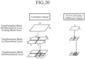
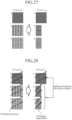
- Fig. 20 is an explanatory drawing showing transformation block sizes at the time of performing a compression process (a transformation process and a quantization process) on the luminance signal and the color difference signals in a signal having the YUV4:2:0 format.
- the transformation block sizes are determined by hierarchically partitioning each coding block into blocks in quadtree form, as shown in Fig. 20 .
- an optimal partitioned shape of the transformation block can be determined from the viewpoint of a trade-off between the code amount and the coding errors.
- the color difference signals are configured, as shown in Fig. 20 , in such a way that when the input signal format is the YUV4:2:0 signal format, each coding block is hierarchically partitioned into one or more square transformation blocks, like the luminance signal.
- each partitioned block is made to consist of two transformation blocks having the same block size as that of the color difference signals in a YUV4:2:0 signal (a size which is half of the size both in the vertical and horizontal directions of the transformation block of the luminance signal).
- the same partitioning as that on the transformation blocks of the luminance signal is always performed on the transformation blocks of the color difference signals in such a way that the transformation blocks are configured to have the same size.
- Information about the partitioning of the luminance signal into the transformation blocks is outputted to the variable length encoding unit 13 as, for example, a transformation block partitioning flag showing whether or not to perform partitioning for each hierarchical layer.
- a select switch 3 performs a process of, when the coding mode determined by the encoding controlling unit 2 is an intra coding mode, outputting the coding block outputted from the block partitioning unit 1 to an intra prediction unit 4, and, when the coding mode determined by the encoding controlling unit 2 is an inter coding mode, outputting the coding block outputted from the block partitioning unit 1 to a motion-compensated prediction unit 5.
- the intra prediction unit 4 performs, when an intra coding mode is selected, as the coding mode associated with the coding block outputted from the select switch 3, by the encoding controlling unit 2, an intra prediction process (intra-frame prediction process) using the intra prediction parameter determined by the encoding controlling unit 2 while referring to a local decoded image stored in a memory 10 for intra prediction, and then performs a process of generating an intra prediction image.
- the intra prediction unit 4 constructs an intra predictor.
- the intra prediction unit 4 performs the intra prediction process (intra-frame prediction process) using the intra prediction parameter of the luminance signal, and generates a prediction image of the luminance signal.
- the intra prediction unit when the intra prediction parameter of the color difference signals shows that the same prediction mode as the intra prediction mode for the luminance signal is used (when the intra prediction parameter shows an intra prediction mode common between the luminance and the color differences (DM mode)), the intra prediction unit performs the same intra-frame prediction as that on the luminance signal, and generates prediction images of the color difference signals.
- the intra prediction unit when the intra prediction parameter of the color difference signals shows a vertical prediction mode or a horizontal prediction mode, the intra prediction unit performs a directional prediction on the color difference signals, and generates prediction images of the color difference signals.
- the intra prediction unit calculates a correlation parameter showing a correlation between the luminance signal and the color difference signals by using the luminance signals and the color difference signals of a plurality of pixels adjacent to the upper and left sides of a block for which a prediction image is to be generated, and generates prediction images of the color difference signals by using both the correlation parameter and the luminance signal associated with the blocks of the color difference signals which are the target for prediction process.
- LM mode luminance correlation
- the intra prediction unit can be configured to, when the input signal format is the YUV4:4:4 signal format, perform a process in either the above-described DM mode or the above-described LM mode, and prevent itself from selecting another prediction mode.
- each of the color difference signals is a rectangular block in which the number of pixels in the horizontal direction is half as compared with that of the luminance signal. Therefore, in order to apply a prediction in the same direction to the luminance signal and the color difference signals when a YUV4:4:4 signal is converted into a YUV4:2:2 signal, as shown in Fig. 28 , the prediction direction of the color difference signals is configured to differ from that of the luminance signal on the YUV4:2:2 signal in the case of a directional prediction other than the vertical prediction and the horizontal prediction.
- the angle of the prediction direction is expressed by theta, as shown in Fig. 30
- it is necessary to perform a prediction in a prediction direction having a relation shown by tan ⁇ C 2tan ⁇ L , where the angle of the prediction direction of the luminance signal is expressed by ⁇ L and the angle of the prediction direction of each of the color difference signals is expressed by ⁇ C .
- the intra prediction unit converts an index of the intra prediction mode which is used for the luminance signal into an index of the intra prediction mode which is used for the prediction on the color difference signals, and performs the prediction process on the color difference signals in the intra prediction mode corresponding to the converted index.
- the intra prediction unit can be configured to convert the index by preparing a conversion table for the index and referring to the conversion table, or a conversion equation can be prepared in advance and the intra prediction unit can be configured to convert the index according to the conversion equation.
- the motion-compensated prediction unit 5 performs, when an inter coding mode is selected, as the coding mode associated with the coding block outputted from the select switch 3, by the encoding controlling unit 2, a process of comparing the coding block with one or more frames of local decoded images stored in a motion-compensated prediction frame memory 12 to search for a motion vector, performing an inter prediction process (motion-compensated prediction process) by using the motion vector and the inter prediction parameter, such as a frame number to be referred to, which is determined by the encoding controlling unit 2, and generating an inter prediction image.
- an inter prediction process motion-compensated prediction process
- a subtracting unit 6 performs a process of subtracting the intra prediction image generated by the intra prediction unit 4 or the inter prediction image generated by the motion-compensated prediction unit 5 from the coding block outputted from the block partitioning unit 1, and outputting a prediction difference signal showing a difference image which is the result of the subtraction to the transformation/quantization unit 7.
- the transformation/quantization unit 7 refers to the transformation block partitioning information included in the prediction difference coding parameters determined by the encoding controlling unit 2 and performs an orthogonal transformation process (e.g., orthogonal transformation process, such as DCT (discrete cosine transform), DST (discrete sine transform), and KL transform in which bases are designed for specific learning sequence in advance) on the prediction difference signal outputted from the subtracting unit 6 on a per transformation block basis to calculate transform coefficients, and also refers to the quantization parameter included in the prediction difference coding parameters and performs a process of quantizing the transform coefficients of each transformation block and then outputting compressed data which are the transform coefficients quantized thereby to the inverse quantization/inverse transformation unit 8 and the variable length encoding unit 13.
- orthogonal transformation process e.g., orthogonal transformation process, such as DCT (discrete cosine transform), DST (discrete sine transform), and KL transform in which bases are designed for specific learning sequence in advance
- DCT discrete cosine transform
- DST
- the transformation/quantization unit 7 can perform a process of quantizing the transform coefficients by using a quantization matrix for scaling, for each of the transform coefficients, the quantization step size calculated from the above-described quantization parameter.
- Fig. 10 is an explanatory drawing showing an example of the quantization matrix of a 4 ⁇ 4 DCT.
- Numerals shown in the figure express scaling values for the quantization stepsizes of the transform coefficients.
- the encoding can be performed without reducing information about coefficients in a low frequency band which exert a great influence upon the subjective quality.
- the quantization matrix a matrix which is independent for each chrominance signal and for each coding mode (intra coding or inter coding) at each orthogonal transformation size can be used, and either the selection of a quantization matrix from a quantization matrix which is prepared, as an initial value, in advance and in common between the image encoding device and the image decoding device and an already-encoded quantization matrix or the use of a new quantization matrix can be selected.
- the transformation/quantization unit 7 sets, to a quantization matrix parameter to be encoded, flag information showing whether or not to use a new quantization matrix for each chrominance signal and for each coding mode at each orthogonal transformation size.
- each of the scaling values in the quantization matrix as shown in Fig. 10 is set to the quantization matrix parameter to be encoded.
- an index specifying a matrix to be used from a quantization matrix which is prepared, as an initial value, in advance and in common between the image encoding device and the image decoding device and an already-encoded quantization matrix is set to the quantization matrix parameter to be encoded.
- no already-encoded quantization matrix which can be referred to exists only a quantization matrix prepared in advance and in common between the image encoding device and the image decoding device can be selected.
- the inverse quantization/inverse transformation unit 8 refers to the quantization parameter and the transformation block partitioning information included in the prediction difference coding parameters determined by the encoding controlling unit 2 and inverse-quantizes the compressed data outputted from the transformation/quantization unit 7 on a per transformation block basis, and also performs an inverse orthogonal transformation process on the transform coefficients which are the compressed data inverse-quantized thereby and performs a process of calculating a local decoding prediction difference signal corresponding to the prediction difference signal outputted from the subtracting unit 6.
- the transformation/quantization unit 7 performs a quantization process by using a quantization matrix
- the quantization matrix is referred to and a corresponding inverse quantization process is performed also in the inverse quantization process.
- An adding unit 9 performs a process of adding the local decoding prediction difference signal calculated by the inverse quantization/inverse transformation unit 8 and the intra prediction image generated by the intra prediction unit 4 or the inter prediction image generated by the motion-compensated prediction unit 5, to calculate a local decoded image corresponding to the coding block outputted from the block partitioning unit 1.
- the memory 10 for intra prediction is a recording medium for storing the local decoded image calculated by the adding unit 9.
- a loop filter unit 11 performs a predetermined filtering process on the local decoded image calculated by the adding unit 9, and performs a process of outputting the local decoded image filtering-processed thereby.
- the loop filter unit performs a filtering (deblocking filtering) process of reducing a distortion occurring at a boundary between transformation blocks and a distortion occurring at a boundary between prediction blocks, a process (pixel adaptive offset process) of adaptively adding an offset on a per pixel basis, an adaptive filtering process of adaptively switching among linear filters, such as Wiener filters, and performing the filtering process, and so on.
- a filtering deblocking filtering
- the filtering processes to be used can be determined according to the processing load acceptable to the image encoding device and the characteristics of images subjected to the encoding process. For example, when there is a demand to reduce the frequency with which the process cannot be performed rather than to provide the configuration shown in Fig. 11 , there can be considered an example in which the loop filter unit is configured with only the deblocking filtering process and the pixel adaptive offset process.
- various parameters to be used for selecting the intensity of the filter applied to a block boundary can be changed from initial values.
- the parameter is outputted to the variable length encoding unit 13 as header information.
- the block partitioning information, an index indicating the class classifying method selected for each block, and offset information specifying the offset value calculated for each class on a per block basis are outputted to the variable length encoding unit 13 as header information.
- the picture data is configured with one or more pieces of slice data, and each slice data is acquired by aggregating the slice level header and the above-described encoded data contained in the slice.
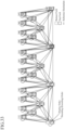
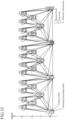
- 33 is set to be a picture at a recovery point (recovery_poc_cnt). Further, it is assumed that at that time a picture whose encoding (decoding) order and also display order are later than those of the above-described recovery point picture (the top field shown by the gray box having a number of 32 in the display order) is prohibited from making a prediction reference to a picture whose display order is earlier than that of the above-described recovery point picture, like in the case of the restriction imposed on trailing pictures.
- Such a picture can be encoded in the encoding (decoding) order as shown in Fig. 33 .
- a leading picture, and a trailing picture an encoded bitstream which can be correctly played back from a top field at all times irrespective of the decoding start position of the encoded bitstream can be generated in the field pair configuration using a bidirectional prediction as shown in Fig. 33 .
- this embodiment is not limited to this example as long as the information can be set to a higher-level header.
- a method of defining, as a new picture type belonging to IRAP pictures, a special IRAP picture which makes it possible to encode only one continuous trailing picture ahead of leading pictures, and encoding the top field having a number of 32 in the display order by using the new IRAP picture and a method of newly defining a special trailing picture which can be encoded ahead of leading pictures, and encoding, as an IRAP picture such as a CRA picture, the top field having a number of 32 in the display order and also encoding, as the special trailing picture as defined above, the bottom field having a number of 33 in the display order.
- units that perform the above-described encoding process and the above-described multiplexing process are an encoder and a multiplexer which the variable
- Fig. 33 has a configuration of performing the decoding from a top field, by configuring an encoded bitstream as mentioned above also in a case of a configuration of performing the encoding, starting from a bottom field at all times, an encoded bitstream which can be correctly played back from a bottom field at all times irrespective of the decoding start position of the encoded bitstream can be generated.
- a program in which the processes performed by the block partitioning unit 1, the encoding controlling unit 2, the select switch 3, the intra prediction unit 4, the motion-compensated prediction unit 5, the subtracting unit 6, the transformation/quantization unit 7, the inverse quantization/inverse transformation unit 8, the adder 9, the loop filter unit 11, the variable length encoding unit 13, and the slice partitioning unit 14 are described can be stored in a memory of the computer and a CPU of the computer can execute the program stored in the memory.
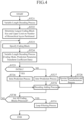
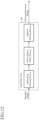
- Fig. 3 is a block diagram showing the image decoding device in accordance with the example of the present invention.
- variable length decoding unit 31 when receiving the encoded bitstream generated by the image encoding device shown in Fig. 1 , decodes each of the pieces of header information, such as sequence level headers, picture level headers, and slice level headers, from the bitstream, and also variable-length-decodes the block partitioning information showing the partitioning state of each of coding blocks partitioned hierarchically from the encoded bitstream.
- each of a YUV4:4:4 format signal and an RGB4:4:4 format signal is a monochrome image signal
- a decoding process can be performed independently on the encoded bitstream of each chrominance signal.
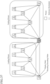
- this top field shown by the gray box having a number of 32 in the display order is a non-IRAP picture, even under conformity with the specifications described in nonpatent reference 1, the process under the restriction that is imposed on leading pictures and trailing pictures and that a leading picture must be decoded (encoded) ahead of trailing pictures is not indispensable, and the encoded bitstream, which is generated on condition that after the bottom field having a number of 33 in the display order, which is a trailing picture, is decoded immediately after the top field having a number of 32 in the display order is decoded, a leading picture is to be decoded, can be decoded correctly, and even if the decoding is started from the above-described top field, the subsequent fields can be decoded and played back correctly in the display order.
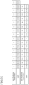
- Recovery Point SEI Message there is provided a case in which the above-described SEI is decoded within the access unit of the picture which is desired to be able to be accessed randomly (the top field shown by the gray box having a number of 32 in the display order), and the value of each of the pieces of syntax shown in Fig. 38 is decoded as will be shown below.
- the corresponding image decoding device can be configured in such a way as to similarly define a special picture as a new type of new NAL unit or the like.
- the image decoding device can recognize that the top field having a number of 32 can be accessed randomly by decoding the above-described information.
- Fig. 33 has a configuration of performing the decoding from a top field, also in a case of an encoded bitstream which is configured in such a way that a bottom field is always encoded before everything else, by using a non-IRAP picture and additional information such as SEI, when performing the decoding from a specific bottom field shown by the additional information, fields subsequent to this specific bottom field can be decoded correctly in the display order.
- additional information such as SEI
- variable length decoding unit 31 variable-length-decodes the quantization matrix parameter and specifies a quantization matrix.
- the variable length decoding unit refers to the index information specifying which quantization matrix in the above-described matrices is used, to specify a quantization matrix, and, when the quantization matrix parameter shows that a new quantization matrix is used, specifies, as the quantization matrix to be used, the quantization matrix included in the quantization matrix parameter.
- the variable length decoding unit 31 also refers to each header information to specify the slice partitioning state and also specify each largest coding block included in the slice data about each slice, refers to the block partitioning information to partition each largest coding block hierarchically and specify each coding block which is a unit on which the decoding process is to be performed, and performs a process of variable-length-decoding the compressed data, the coding mode, the intra prediction parameter (when the coding mode is an intra coding mode), the inter prediction parameter (when the coding mode is inter encoding mode), the motion vector (when the coding mode is an inter coding mode), and the prediction difference coding parameters, which are associated with each coding block.
- An inverse quantization/inverse transformation unit 32 refers to the quantization parameter and the transformation block partitioning information which are included in the prediction difference coding parameters variable-length-decoded by the variable length decoding unit 31, to inverse-quantize the compressed data variable-length-decoded by the variable length decoding unit 31 on a per transformation block basis, performs an inverse orthogonal transformation process on the transform coefficients which are the compressed data inverse-quantized thereby, and performs a process of calculating a decoding prediction difference signal which is the same as the local decoding prediction difference signal outputted from the inverse quantization/inverse transformation unit 8 shown in Fig. 1 .
- the partitioning state of the transformation blocks in each coding block is determined.
- the transformation block sizes are determined by performing hierarchical partitioning of each coding block into blocks in quadtree form, as shown in Fig. 20 .
- the luminance signal is configured in such a way that each coding block is hierarchically partitioned into one or more of square transformation blocks, as shown in, for example, Fig. 20 .
- Each of the color difference signals is configured in such a way that when the input signal format is the YUV4:2:0 signal format, each coding block is hierarchically partitioned into one or more of square transformation blocks, as shown in Fig. 20 , like the luminance signal.
- the transformation block size of each of the color difference signals is half of that of the corresponding luminance signal both in the vertical and horizontal directions.
- the same partitioning as that on the transformation blocks of the luminance signal is always performed on the transformation blocks of each of the color difference signals in such a way that the transformation blocks are configured to have the same sizes.
- variable length decoding unit 31 when each header information variable-length-decoded by the variable length decoding unit 31 shows that in the slice currently being processed, an inverse quantization process is performed by using a quantization matrix, the inverse quantization process is performed by using the quantization matrix.
- the inverse quantization/inverse transformation unit performs the inverse quantization process by using the quantization matrix specified from each header information.
- a select switch 33 performs a process of, when the coding mode variable-length-decoded by the variable length decoding unit 31 is an intra coding mode, outputting the intra prediction parameter which is variable-length-decoded by the variable length decoding unit 31 to an intra prediction unit 34, whereas when the coding mode variable-length-decoded by the variable length decoding unit 31 is an inter coding mode, outputting the inter prediction parameter and the motion vector which are variable-length-decoded by the variable length decoding unit 31 to a motion compensation unit 35.
- the intra prediction unit when the intra prediction parameter of the color difference signals shows that the same prediction mode as the intra prediction mode for the luminance signal is used (when the intra prediction parameter shows the intra prediction mode common between the luminance and the color differences (DM mode)), the intra prediction unit performs the same intra-frame prediction as that on the luminance signal, to generate prediction images of the color difference signals.
- the intra prediction unit performs the directional prediction on the color difference signals to generate prediction images of the color difference signals.
- each of the color difference signals is a rectangular block in which the number of pixels in the horizontal direction is half as compared with that of the luminance signal. Therefore, in order to apply a prediction in the same direction to the luminance signal and the color difference signals when a YUV4:4:4 signal is converted into a YUV4:2:2 signal, as shown in Fig. 28 , the prediction direction of the color difference signals is configured to differ from that of the luminance signal on the YUV4:2:2 signal in the case of a directional prediction other than the vertical prediction and the horizontal prediction.
- the intra prediction unit converts an index of the intra prediction mode which is used for the luminance signal into an index of the intra prediction mode which is used for the prediction on the color difference signals, and performs the prediction process on the color difference signals in the intra prediction mode corresponding to the converted index.
- a conversion table for the index can be prepared and the intra prediction unit can be configured to convert the index by referring to the conversion table, or a conversion equation can be prepared in advance and the intra prediction unit can be configured to convert the index according to the conversion equation.
- the intra prediction unit can perform an appropriate prediction on the color difference signals according to the YUV4:2:2 signal format only by performing the conversion of the index without changing the directional prediction process itself.
- the motion compensation unit 35 performs a process of, when the coding mode associated with the coding block determined from the block partitioning information variable-length-decoded by the variable length decoding unit 31 is an inter coding mode, performing an inter prediction process (motion-compensated prediction process) using the motion vector and the inter prediction parameter which are outputted from the select switch 33 while referring to a decoded image stored in a motion-compensated prediction frame memory 39, and generating an inter prediction image.
- an inter prediction process motion-compensated prediction process
- An adding unit 36 performs a process of adding the decoding prediction difference signal calculated by the inverse quantization/inverse transformation unit 32 and the intra prediction image generated by the intra prediction unit 34 or the inter prediction image generated by the motion compensation unit 35, to calculate a decoded image which is the same as the local decoded image outputted from the adding unit 9 shown in Fig. 1 .
- the memory 37 for intra prediction is a recording medium that stores the decoded image calculated by the adder 36 as a reference image used for intra prediction process.
- a loop filter unit 38 performs a predetermined filtering process on the decoded image calculated by the adding unit 36, and performs a process of outputting the decoded image filtering-processed thereby.
- the loop filter unit performs a filtering (deblocking filtering) process of reducing a distortion occurring at a boundary between transformation blocks and a distortion occurring at a boundary between prediction blocks, a process (pixel adaptive offset process) of adaptively adding an offset on a per pixel basis, an adaptive filtering process of adaptively switching among linear filters, such as Wiener filters, and performing the filtering process, and so on.
- a filtering deblocking filtering
- the loop filter unit 38 refers to each header information variable-length-decoded by the variable length decoding unit 31 and specifies whether or not to perform the process in the slice currently being processed.
- the loop filter unit 38 is configured as shown in Fig. 12 .
- the loop filter unit 38 is also configured with the deblocking filtering process and the pixel adaptive offset process.
- the loop filter unit refers to the header information variable-length-decoded by the variable length decoding unit 31, and, when there exists information for changing the various parameters used for the selection of the intensity of a filter applied to a block boundary from initial values, performs the deblocking filtering process on the basis of the change information.
- the loop filter unit performs the deblocking filtering process according to a predetermined method.
- the loop filter unit partitions the decoded image into blocks on the basis of the block partitioning information for the pixel adaptive offset process, which is variable-length-decoded by the variable length decoding unit 31, refers to the index variable-length-decoded by the variable length decoding unit 31 and indicating the class classifying method of each of the blocks on a per block basis, and, when the index does not indicate "does not perform the offset process", performs a class classification on each pixel in each of the blocks according to the class classifying method indicated by the above-described index.
- the loop filter unit then refers to the offset information specifying the offset value calculated for each class on a per block basis, and performs a process of adding the offset to the luminance value of the decoded image.
- the pixel adaptive offset process in the loop filter unit 11 of the image encoding device is configured in such a way as to, instead of encoding the block partitioning information, always partition the image into blocks each having a fixed size (e.g., largest coding blocks), select a class classifying method for each of the blocks, and perform an adaptive offset process on a per class basis, a pixel adaptive offset process is performed also in the loop filter unit 38 for each block having a fixed size which is the same as that in the loop filter unit 11.
- a fixed size e.g., largest coding blocks
- the loop filter unit After performing a class classification according to the same method as that used by the image encoding device of Fig. 1 , the loop filter unit performs the filtering process by using the filter for each class, which is variable-length-decoded by the variable length decoding unit 31, on the basis of information about the class classification.
- the motion-compensated prediction frame memory 39 is a recording medium that stores the decoded image filtering-processed by the loop filter unit 38 as a reference image used for inter prediction process (motion-compensated prediction process).
- variable length decoding unit 31, the inverse quantization/inverse transformation unit 32, the select switch 33, the intra prediction unit 34, the motion compensation unit 35, the adder 36, the memory 37 for intra prediction, the loop filter unit 38, and the motion-compensated prediction frame memory 39 which are the components of the image decoding device, are assumed to be configured with pieces of hardware for exclusive use (e.g., semiconductor integrated circuits in each of which a CPU is mounted, one chip microcomputers, or the like).
- a program in which the processes performed by the variable length decoding unit 31, the inverse quantization/inverse transformation unit 32, the select switch 33, the intra prediction unit 34, the motion compensation unit 35, the adder 36, and the loop filter unit 38 are described can be stored in a memory of the computer and a CPU of the computer can execute the program stored in the memory.
- Fig. 4 is a flow chart showing the processing (image decoding method) performed by the image decoding device in accordance with the example of the present invention.
- the image encoding device receives each frame image of a video as an input image, performs an intra prediction based on already-encoded neighboring pixels or a motion-compensated prediction between adjacent frames, performs a compression process with orthogonal transformation and quantization on an acquired prediction difference signal, and, after that, performs variable length encoding to generate an encoded bitstream, and the image decoding device decodes the encoded bitstream outputted from the image encoding device.
- the image encoding device shown in Fig. 1 is characterized in that the device is adapted for local changes of a video signal in a space direction and in a time direction, partitions the video signal into blocks having various sizes, and performs intra-frame and inter-frame adaptive encoding.
- video signals have characteristics of their complexity locally varying in space and time.
- a certain video frame may have, for example, a pattern having a uniform signal characteristic in a relatively large image region, such as a sky image or a wall image, or a pattern in which a pattern having a complicated texture in a small image region, such as a person image or a picture including a fine texture, also coexists.
- a sky image and a wall image have a small local change in a time direction in their patterns, while an image of a moving person or object has a larger temporal change because its outline has a movement of a rigid body and a movement of a non-rigid body with respect to time.
- the code amount of parameters used for the prediction can be reduced as long as the parameters can be applied uniformly to as large an image signal region as possible.
- the code amount of the prediction difference signal increases.
- the size of a block subjected to the prediction process to which the same prediction parameter is applied is reduced, thereby increasing the data volume of the parameter which is used for the prediction and reducing the electric power and entropy of the prediction difference signal.
- a configuration is employed in which the prediction process and so on are started first from a predetermined largest block size, the region of the video signal is hierarchically partitioned, and the prediction process and the encoding process on the prediction difference are adapted for each of the partitioned regions.
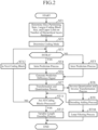
- the encoding controlling unit 2 determines the slice partitioning state of a picture (current picture) which is the target to be encoded, and also determines the size of each largest coding block which is used for the encoding of the picture and the upper limit on the number of hierarchical layers at the time when each largest coding block is hierarchically partitioned into blocks (step ST1 of Fig. 2 ).
- a method of determining the size of each largest coding block for example, there can be a method of determining the same size for all the pictures according to the resolution of the video signal of the inputted image, and a method of quantifying a variation in the complexity of a local movement of the video signal of the inputted image as a parameter and then determining a small size for a picture having a vigorous movement while determining a large size for a picture having a small movement.
- a method of determining the upper limit on the number of hierarchical layers partitioned for example, there can be a method of determining the same number of hierarchical layers for all the pictures according to the resolution of the video signal of the inputted image, and a method of determining an increased number of hierarchical layers so that a finer movement can be detected when the video signal of the inputted image has a vigorous movement, while determining a decreased number of hierarchical layers when the video signal of the inputted image has a small movement.
- each largest coding block and the upper limit on the number of hierarchical layers into which each largest coding block is hierarchically partitioned can be encoded into the sequence level header or the like, or, instead of encoding the size and the number, the image decoding device can be configured in such a way as to also perform the same determination process.
- the code amount of the header information increases.
- the image decoding device does not have to perform the above-described determination process, the processing load on the image decoding device can be reduced and, in addition to that, the image encoding device can search for and send an optimal value.
- the image decoding device can determine the upper limit on the number of hierarchical layers partitioned from the size of the largest coding blocks and the smallest block size of the coding blocks.
- the encoding controlling unit 2 also selects a coding mode corresponding to each of the coding blocks into which each inputted image is hierarchically partitioned from one or more available coding modes (step ST2).
- the encoding controlling unit 2 hierarchically partitions each image region having the largest coding block size into coding blocks each having a coding block size until the number of hierarchical layers partitioned reaches the upper limit which is determined in advance, and determines a coding mode for each of the coding blocks.
- the coding mode is one of one or more intra coding modes (generically referred to as "INTRA”) and one or more inter coding modes (generically referred to as "INTER”), and the encoding controlling unit 2 selects a coding mode corresponding to each of the coding blocks from among all the coding modes available in the picture currently being processed or a subset of these coding modes.
- the selecting method is a known technique
- the encoding controlling unit 2 further determines a quantization parameter and a transformation block partitioning state, which are used when a difference image is compressed, for each coding block, and also determines a prediction parameter (intra prediction parameter or inter prediction parameter) which is used when a prediction process is performed.
- a prediction parameter (intra prediction parameter or inter prediction parameter) can be selected for each of the prediction blocks.
- Fig. 20 is an explanatory drawing showing transformation block sizes at the time of performing the compression process (the transformation process and quantization process) on the luminance signal and the color difference signals in a 4:2:0 format signal.
- the transformation block sizes are determined by hierarchically partitioning each coding block into blocks in quadtree form, as shown in Fig. 20 .
- an optimal partitioned shape of the transformation block can be determined from the viewpoint of a trade-off between the code amount and the coding errors.
- the luminance signal is configured, as shown in, for example, Fig. 20 , in such a way that each coding block is hierarchically partitioned into one or more square transformation blocks.
- the color difference signals are configured, as shown in Fig. 20 , in such a way that when the input signal format is the YUV4:2:0 signal format, each coding block is hierarchically partitioned into one or more square transformation blocks, like the luminance signal.
- the transformation block size of each of the color difference signals is half of that of the corresponding luminance signal both in the vertical and horizontal directions.
- each partitioned block is made to consist of two transformation blocks having the same block size as that of the color difference signals in a YUV 4:2:0 signal (a size which is half of the size both in the vertical and horizontal directions of each transformation block of the luminance signal).
- the same partitioning as that on the transformation blocks of the luminance signal is always performed on the transformation blocks of each of the color difference signals in such a way that the transformation blocks are configured to have the same sizes.
- the encoding controlling unit 2 outputs the prediction difference coding parameters including the transformation block partitioning information showing the partitioning information about the transformation blocks in each coding block, and the quantization parameter defining the quantization step size at the time of performing quantization on the transform coefficients to the transformation/quantization unit 7, the inverse quantization/inverse transformation unit 8, and the variable length encoding unit 13.
- the encoding controlling unit 2 also outputs the intra prediction parameter to the intra prediction unit 4 as needed.
- the encoding controlling unit 2 further outputs the inter prediction parameter to the motion-compensated prediction unit 5 as needed.
- the slice partitioning unit 14 partitions the inputted image into one or more slices which are part images according to the slice partitioning information determined by the encoding controlling unit 2.
- the block partitioning unit 1 partitions the slice into coding blocks each having the largest coding block size determined by the encoding controlling unit 2, and further partitions each of the largest coding blocks partitioned into coding blocks hierarchically, these coding blocks being determined by the encoding controlling unit 2, and outputs each of the coding blocks.
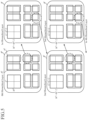
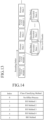
- Fig. 5 is an explanatory drawing showing an example in which each largest coding block is hierarchically partitioned into a plurality of coding blocks.
- each largest coding block is a coding block whose luminance component, which is shown by "0-th hierarchical layer", has a size of (L 0 , M 0 ).
- the coding blocks are acquired.
- each coding block is an image region having a size of (L n , M n ).
- the coding block size determined by the encoding controlling unit 2 is defined as the size of (L n , M n ) in the luminance component of each coding block.
- each coding block in the nth hierarchical layer is expressed by B n
- a coding mode selectable for each coding block B n is expressed by m(B n ).
- the coding mode m(B n ) can be configured in such a way that an individual mode is used for each color component, or can be configured in such a way that a common mode is used for all the color components.
- the coding mode indicates a coding mode for the luminance component of each coding block when having the 4:2:0 format in a YUV signal unless otherwise specified.
- Each coding block B n is partitioned into one or more prediction blocks each representing a unit for prediction process by the block partitioning unit 1, as shown in Fig. 5 .
- each prediction block belonging to each coding block B n is expressed by P i n (i shows a prediction block number in the nth hierarchical layer).
- P i n shows a prediction block number in the nth hierarchical layer.
- An example of P 0 0 and P 1 0 is shown in Fig. 5 .
- an individual prediction parameter (an intra prediction parameter or an inter prediction parameter) can be selected for each prediction block P i n .
- the encoding controlling unit 2 generates such a block partitioning state as shown in Fig. 6 for each largest coding block, and then specifies coding blocks.
- Each rectangle enclosed by a dotted line of Fig. 6(a) shows a coding block, and each block filled with hatch lines in each coding block shows the partitioning state of each prediction block.
- Information about this quadtree graph is outputted from the encoding controlling unit 2 to the variable length encoding unit 13 together with the coding mode m(B n ), and is multiplexed into a bitstream.
- the select switch 3 When the coding mode m(B n ) determined by the encoding controlling unit 2 is an intra coding mode (when m(B n ) ⁇ INTRA), the select switch 3 outputs the coding block B n outputted from the block partitioning unit 1 to the intra prediction unit 4.
- the select switch outputs the coding block B n outputted from the block partitioning unit 1 to the motion-compensated prediction unit 5.
- the intra prediction unit 4 When the coding mode m(B n ) determined by the encoding controlling unit 2 is an intra coding mode (when m(B n ) ⁇ INTRA), and the intra prediction unit 4 receives the coding block B n from the select switch 3 (step ST3), the intra prediction unit 4 performs the intra prediction process on each prediction block P i n in the coding block B n by using the intra prediction parameter determined by the encoding controlling unit 2 while referring to the local decoded image stored in the memory 10 for intra prediction, to generate an intra prediction image P INTRAi n (step ST4).
- the selectable block sizes of the transformation blocks are limited to sizes equal to or smaller than the size of the prediction blocks.
- an intra prediction process using the intra prediction parameter determined for this prediction block is performed and the process of generating an intra prediction image is performed on a per transformation block basis.
- the intra prediction parameter used for generating the intra prediction image P INTRAi n is outputted from the encoding controlling unit 2 to the variable length encoding unit 13, and is multiplexed into the bitstream.
- the motion-compensated prediction unit 5 compares each prediction block P i n in the coding block B n with the local decoded image which is stored in the motion-compensated prediction frame memory 12 and on which the filtering process is performed, to search for a motion vector, and performs the inter prediction process on each prediction block P i n in the coding block B n by using both the motion vector and the inter prediction parameter determined by the encoding controlling unit 2, to generate an inter prediction image P INTERi n (step ST5) .
- the inter prediction parameter used for generating the inter prediction image P INTERi n is outputted from the encoding controlling unit 2 to the variable length encoding unit 13, and is multiplexed into the bitstream.
- the motion vector which is searched for by the motion-compensated prediction unit 5 is also outputted to the variable length encoding unit 13 and is multiplexed into the bitstream.
- the subtracting unit 6 When receiving the coding block B n from the block partitioning unit 1, the subtracting unit 6 subtracts the intra prediction image P INTRAi n generated by the intra prediction unit 4 or the inter prediction image P INTERi n generated by the motion-compensated prediction unit 5 from the prediction block P i n in the coding block B n , and outputs a prediction difference signal e i n showing a difference image which is the result of the subtraction to the transformation/quantization unit 7 (step ST6) .
- the transformation/quantization unit 7 When receiving the prediction difference signal e i n from the subtracting unit 6, the transformation/quantization unit 7 refers to the transformation block partitioning information included in the prediction difference coding parameters determined by the encoding controlling unit 2, and performs an orthogonal transformation process (e.g., an orthogonal transformation process, such as a DCT (discrete cosine transform), a DST (discrete sine transform), or a KL transform in which bases are designed for a specific learning sequence in advance) on the prediction difference signal e i n on a per transformation block basis, to calculate transform coefficients.
- an orthogonal transformation process e.g., an orthogonal transformation process, such as a DCT (discrete cosine transform), a DST (discrete sine transform), or a KL transform in which bases are designed for a specific learning sequence in advance
- the transformation/quantization unit 7 also refers to the quantization parameter included in the prediction difference coding parameters and quantizes the transform coefficients of each transformation block, and outputs compressed data which are the transform coefficients quantized thereby to the inverse quantization/inverse transformation unit 8 and the variable length encoding unit 13 (step ST7).
- the transformation/quantization unit can perform the quantization process by using a quantization matrix for performing scaling on the quantization step size calculated from the above-described quantization parameter for each transform coefficient.
- the quantization matrix a matrix which is independent for each chrominance signal and for each coding mode (intra encoding or inter encoding) at each orthogonal transformation size can be used, and either the selection of a quantization matrix from a quantization matrix which is prepared, as an initial value, in advance and in common between the image encoding device and the image decoding device and an already-encoded quantization matrix or the use of a new quantization matrix can be selected.
- the transformation/quantization unit 7 sets flag information showing whether or not to use a new quantization matrix for each chrominance signal and for each coding mode at each orthogonal transformation size to a quantization matrix parameter to be encoded.
- each of the scaling values in the quantization matrix as shown in Fig. 10 is set to the quantization matrix parameter to be encoded.
- an index specifying a matrix to be used from a quantization matrix which is prepared, as an initial value, in advance and in common between the image encoding device and the image decoding device and an already-encoded quantization matrix is set to the quantization matrix parameter to be encoded.
- no already-encoded quantization matrix which can be referred to exists only a quantization matrix prepared in advance and in common between the image encoding device and the image decoding device can be selected.
- the transformation/quantization unit 7 then outputs the quantization matrix parameter set thereby to the variable length encoding unit 13.
- the inverse quantization/inverse transformation unit 8 When receiving the compressed data from the transformation/quantization unit 7, the inverse quantization/inverse transformation unit 8 refers to the quantization parameter and the transformation block partitioning information which are included in the prediction difference coding parameters determined by the encoding controlling unit 2, and inverse-quantizes the compressed data on a per transformation block basis.
- the inverse quantization/inverse transformation unit refers to the quantization matrix and performs a corresponding inverse quantization process also at the time of the inverse quantization process.
- the inverse quantization/inverse transformation unit 8 also performs an inverse orthogonal transformation process (e.g., an inverse DCT, an inverse DST, an inverse KL transform, or the like) on the transform coefficients, which are the compressed data inverse-quantized, on a per transformation block basis, and calculates a local decoding prediction difference signal corresponding to the prediction difference signal e i n outputted from the subtracting unit 6 and outputs the local decoding prediction difference signal to the adding unit 9 (step ST8).
- an inverse orthogonal transformation process e.g., an inverse DCT, an inverse DST, an inverse KL transform, or the like
- the adding unit 9 calculates a local decoded image by adding the local decoding prediction difference signal and either the intra prediction image P INTRAi n generated by the intra prediction unit 4 or the inter prediction image P INTERi n generated by the motion-compensated prediction unit 5 (step ST9).
- the adding unit 9 outputs the local decoded image to the loop filter unit 11 while storing the local decoded image in the memory 10 for intra prediction.
- This local decoded image is an encoded image signal which is used at the time of subsequent intra prediction processes.
- the loop filter unit performs a filtering (deblocking filtering) process of reducing a distortion occurring at a boundary between transformation blocks and a distortion occurring at a boundary between prediction blocks, a process (pixel adaptive offset process) of adaptively adding an offset on a per pixel basis, an adaptive filtering process of adaptively switching among linear filters, such as Wiener filters, and performing a filtering process, and so on.
- a filtering deblocking filtering
- the loop filter unit 11 determines whether or not to perform the process for each of the above-described filtering processes including the deblocking filtering process, the pixel adaptive offset process, and the adaptive filtering process, and outputs the enable flag of each of the processes, as a part of the sequence level header and a part of the slice level header, to the variable length encoding unit 13.
- the loop filter unit performs each of the filtering processes in order.
- Fig. 11 shows an example of the configuration of the loop filter unit 11 in the case of using a plurality of filtering processes.
- various parameters used for the selection of the intensity of a filter to be applied to a block boundary can be changed from initial values.
- the parameter is outputted to the variable length encoding unit 13 as header information.
- a method referred to as a BO method
- a method referred to as an EO method
- a method referred to as an edge portion
- the filter designed for each class is then outputted to the variable length encoding unit 13 as header information.
- flag information showing whether a significant (non-zero) coefficient exists in the 16 coefficients in the CG is encoded first, whether or not each coefficient in the CG is a significant (non-zero) coefficient is then encoded in the above-described order only when a significant (non-zero) coefficient exists in the CG, and, for each significant (non-zero) coefficient, information about its coefficient value is finally encoded in order. This process is performed in the above-described order on a per CG basis.
- variable length encoding unit 13 also encodes sequence level headers and picture level headers, as the header information of an encoded bitstream, as illustrated in Fig. 13 , and generates an encoded bitstream as well as picture data.
- Picture data consists of one or more slice data, and each slice data is a combination of a slice level header and encoded data as mentioned above in the slice currently being processed.
- a picture level header is a combination of pieces of header information which are set on a per picture basis, the pieces of header information including an index of a sequence level header to be referred to, the number of reference pictures at the time of motion compensation, a probability table initialization flag for entropy coding, and so on.
- the intra prediction unit 4 refers to the intra prediction parameter of each prediction block P i n and performs the intra prediction process on the prediction block P i n to generate an intra prediction image P INTRAi n , as mentioned above.
- an intra process of generating an intra prediction image of each prediction block P i n in the luminance signal will be explained.
- the size of a prediction image generation block is l i n ⁇ m i n pixels.
- the number of pixels used for prediction can be larger or smaller than that of the pixels shown in Fig. 8 .
- the intra prediction unit determines the mean value of the already-encoded pixels adjacent to the top of the prediction image generation block and the already-encoded pixels adjacent to the left of the prediction image generation block as the predicted value of each pixel in the prediction image generation block and generates a prediction image.
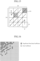
- a filtering process of smoothing a block boundary is performed on regions A, B, and C of Fig. 17 located at the upper edge and at the left edge of the prediction image generation block, and a final prediction image is generated.
- the filtering process is performed by using the following filter coefficients.
- a change of the prediction residual signal which is caused by this variation in the predicted value is not expressed by such a high frequency component as mentioned at the time of a block having a large block size, and the residual signal can be encoded appropriately and the quality of the decoded image can be improved by such an extent that the continuity of a block boundary is improved by using this filtering process.
- the block size of the prediction image generation block on which the above-described filtering process is to be performed can be limited according to the transformation block size.
- the above-described filtering process is not applied to prediction image generation blocks having a block size equal to or larger than max(16, MaxTUsize), but the above-described filtering process is applied only to blocks having a size smaller than max(16, MaxTUsize).
- MaxTUsize shows the largest transformation block size which each transformation block can have
- "16" shows a predetermined block size (16 ⁇ 16 pixels) .
- MaxTUsize 8 ⁇ 8 pixel blocks
- MaxTUsize 8 at which no 16 ⁇ 16 pixel block exists
- the above-described filtering process is performed on all the pixel blocks (8 ⁇ 8 and 4 ⁇ 4).
- MaxTUsize 4
- max(16, 4) 16
- MaxTUsize 4 at which only 4 ⁇ 4 pixel blocks exist
- the above-described filtering process is performed on all the pixel blocks (4 ⁇ 4).
- the filtering process causes a distortion at a block boundary of the decoded image, as described above, the filtering process is prevented from being performed on a flat portion in which the sensitivity is particularly high as a human being's visual sense characteristic, in order to suppress such a distortion, and the above-described filtering process is performed on a block having a small block size, such as a complicated region in which there is a tendency that a reduction of the block size makes it possible to perform the encoding efficiently, so that there is provided an advantage of improving the prediction efficiency and improving the quality of the decoded image.
- the filtering process is performed only on the regions A and C when the flag of a sequence level header showing whether or not the field encoding is performed is valid, the same filtering process as that on the region C can be performed also on the region A.
- the possibility of reduction of the prediction efficiency can be further lowered while the amount of computations required for the filtering process can be reduced.
- no filtering process can be performed also on the region A and the filtering process can be performed only on the region C.
- coordinates (x, y) are relative coordinates (refer to Fig. 9 ) acquired with the pixel at the upper left corner in the prediction image generation block being defined as the point of origin
- S' (x, y) is the predicted value at the coordinates (x, y)
- S(x, y) is the brightness value (decoded brightness value) of the already-encoded pixel at the coordinates (x, y).
- the predicted value exceeds a range of values which the brightness value can have, the predicted value is rounded in such a way as to fall within the range.
- An expression in the first line of the equation (2) means that by adding a value which is one-half of the amount of change (S(-1, y) - S(-1, -1)) in the vertical direction of the brightness values of adjacent already-encoded pixels to S(x, -1) which is the predicted value acquired by the vertical prediction in MPEG-4 AVC/H.264, the filtering process is performed in such a way that a block boundary is smoothed, and an expression in the second line of the equation (2) shows the same prediction expression as that for the vertical prediction in MPEG-4 AVC/H.264.
- the intra prediction unit calculates the predicted value of each pixel in the prediction image generation block according to the following equation (3), and generates a prediction image.
- S ′ x y S ⁇ 1 , y + S x , ⁇ 1 ⁇ S ⁇ 1 , ⁇ 1 ⁇ 1 y ⁇ 0 S ⁇ 1 , y y > 0
- coordinates (x, y) are relative coordinates (refer to Fig. 9 ) acquired with the pixel at the upper left corner in the prediction image generation block being defined as the point of origin
- S' (x, y) is the predicted value at the coordinates (x, y)
- S(x, y) is the brightness value (decoded brightness value) of the already-encoded pixel at the coordinates (x, y).
- the predicted value exceeds a range of values which the brightness value can have, the predicted value is rounded in such a way as to fall within the range.
- An expression in the first line of the equation (3) means that by adding a value which is one-half of the amount of change (S (x, -1) - S(-1, -1)) in the horizontal direction of the brightness values of adjacent already-encoded pixels to S(-1, y) which is the predicted value acquired by the horizontal prediction in MPEG-4 AVC/H.264, the filtering process is performed in such a way that a block boundary is smoothed, and an expression in the second line of the equation (3) shows the same prediction expression as that for the horizontal prediction in MPEG-4 AVC/H.264.
- the block size of the prediction image generation block on which the vertical prediction according to the equation (2) and the horizontal prediction according to the equation (3) are to be performed can be limited.
- a change of the prediction residual signal which is caused by this variation in the predicted value is not expressed by such a high frequency component as mentioned at the time of a block having a large block size, and the residual signal can be encoded appropriately and the quality of the decoded image can be improved by such an extent that the continuity of a block boundary is improved by using this filtering process.
- the block size of the prediction image generation block on which the vertical prediction according to the equation (2) and the horizontal prediction according to the equation (3) are to be performed can be limited according to the transformation block size.
- the expressions in the second lines of the equations (2) and (3) are always used regardless of the coordinates of the target pixel for prediction (the filtering process on the block edges of the prediction image generation block is not performed), and the equations (2) and (3) according to which the above-described filtering process is performed are applied only to blocks having a size smaller than max(16, MaxTUsize).
- "MaxTUsize" shows the largest transformation block size which each transformation block can have
- "16" shows a predetermined block size (16 ⁇ 16 pixels) .
- MaxTUsize 8 ⁇ 8 pixel blocks
- MaxTUsize 8 at which no 16 ⁇ 16 pixel block exists
- the above-described filtering process is performed on all the pixel blocks (8 ⁇ 8 and 4 ⁇ 4).
- MaxTUsize 4
- max(16, 4) 16
- MaxTUsize 4 at which only 4 ⁇ 4 pixel blocks exist
- the above-described filtering process is performed on all the pixel blocks (4 ⁇ 4).
- the filtering process causes a distortion at a block boundary of the decoded image, as mentioned above, the filtering process is prevented from being performed on a flat portion in which its sensitivity is particularly high as a human being's visual sense characteristic, in order to suppress such a distortion, and, by performing the above-described filtering process on a block having a small block size, such as a complicated region in which there is a tendency that reduction of the block size makes it possible to perform the encoding efficiently, there is provided an advantage of improving the prediction efficiency and improving the quality of the decoded image.
- the filtering process is prevented from being performed on the upper edge of the prediction image generation block (in the case of the mean value prediction and the vertical prediction, the filtering process is performed only on the left edge of the prediction image generation block, whereas in the case of the horizontal prediction, the filtering process is not performed), as shown in Fig. 19 .
- the flag of a sequence level header showing whether or not the field encoding is performed can be prepared in each picture level header, and the ON/OFF switching of the filtering process on the upper edge of the prediction image generation block in the mean value (DC) prediction and in the horizontal prediction can be performed according to the correlation between pixels in the vertical direction of each picture.
- DC mean value
- a flag showing whether or not this switching process is performed can be defined independently from the flag of a sequence level header or a picture level header showing whether or not the field encoding is performed, and the ON/OFF of the filtering process on the upper edge of the prediction image generation block can be switched on the basis of this flag showing whether or not the switching process is performed.
- each reference pixel which is used for prediction is located at a point of intersection of L shown below and an adjacent pixel.
- L x y + kv ⁇ where k is a negative real number.
- the value of the integer pixel is determined as the predicted value of the target pixel for prediction, whereas when a reference pixel is not at an integer pixel position, the value of an interpolation pixel generated from integer pixels which are adjacent to the reference pixel is determined as the predicted value.
- the predicted value is interpolated from the values of two pixels adjacent to the reference pixel.
- the intra prediction unit can use, instead of only the adjacent two pixels, adjacent two or more pixels to generate an interpolation pixel and determine the value of this interpolation pixel as the predicted value.
- the intra prediction unit generates prediction pixels for all the pixels of the luminance signal in the prediction block P i n on a per prediction image generation block basis, and outputs an intra prediction image P INTRAi n .
- the intra prediction parameter (intra prediction mode) used for the generation of the intra prediction image P INTRAi n is outputted to the variable length encoding unit 13 in order to multiplex the intra prediction parameter into the bitstream.
- the intra prediction unit 4 is configured in such a way that an already-encoded pixel adjacent to the prediction image generation block on which a smoothing process is performed is provided as the reference pixel at the time of generating a prediction image of the prediction image generation block, the filtering process which is the same as that in the above-described example can be performed on the prediction image.
- the noise of the reference pixel which is caused by the filtering process on the reference pixel can be removed, and the accuracy of the prediction can be improved by performing the prediction by using this configuration.
- the above-described filtering process on the reference pixel can be configured to be performed only at the time of a prediction including the step of performing the filtering process on the prediction image, other than the mean value prediction, the vertical prediction, and the horizontal prediction.
- the intra prediction unit has only to perform one filtering process at the maximum for each prediction mode, and the increase in the amount of computations can be suppressed.
- prediction images for the color difference components are generated as follows.
- the intra prediction unit performs an intra prediction process based on the intra prediction parameter (intra prediction mode) of the color difference signals on the color difference signals of the prediction block P i n , and outputs the intra prediction parameter used for the generation of the intra prediction image to the variable length encoding unit 13.
- Fig. 23 is an explanatory drawing showing an example of a correspondence between the intra prediction parameter (index value) and a color difference intra prediction mode of the color difference signals.
- the intra prediction unit When the intra prediction parameter of the color difference signals shows that the same prediction mode as the intra prediction mode for the luminance signal is used (when the intra prediction parameter shows the intra prediction mode common between the luminance and the color differences (DM mode)), the intra prediction unit performs the same intra-frame prediction as that on the luminance signal, to generate prediction images of the color difference signals.
- the intra prediction unit when the intra prediction parameter of the color difference signals shows the vertical prediction mode or the horizontal prediction mode, the intra prediction unit performs a directional prediction on the color difference signals to generate prediction images of the color difference signals.
- the intra prediction unit calculates a correlation parameter showing the correlation between the luminance signal and the color difference signals by using the luminance signals and the color difference signals of a plurality of pixels adjacent to the upper and left sides of a block for which a prediction image is to be generated, and generates prediction images of the color difference signals by using both the correlation parameter and the luminance signal associated with the block of each of the color difference signals which is the target for prediction process.
- LM mode luminance correlation
- the intra prediction unit can be configured to perform the process in the above-described DM mode or the above-described LM mode and prevent itself from selecting another prediction mode when the input signal format is the YUV4:4:4 signal format. Because there is a high correlation between the edge position of the luminance signal and those of the color difference signals in a YUV4:4:4 signal, by prohibiting the application of a prediction mode different from that applied to the luminance signal to the color difference signals, the amount of information in the intra prediction mode of the color difference signals can be reduced and the coding efficiency can be improved.
- the intra prediction unit can be configured to select, for the color difference signals, a directional prediction mode different from that for the luminance signal also in the case of a YUV4:4:4 signal.
- each of the color difference signals is a rectangular block in which the number of pixels in the horizontal direction is half as compared with that of the luminance signal. Therefore, in order to apply a prediction in the same direction to the luminance signal and the color difference signals when a YUV4:4:4 signal is converted into a YUV4:2:2 signal, as shown in Fig. 28 , the prediction direction of the color difference signals is configured to differ from that of the luminance signal on the YUV4:2:2 signal in the case of a directional prediction other than the vertical prediction and the horizontal prediction.
- the intra prediction unit converts an index of the intra prediction mode which is used for the luminance signal into an index of the intra prediction mode which is used for the prediction on the color difference signals, and performs the prediction process on the color difference signals according to the intra prediction mode corresponding to the converted index.
- Fig. 31 shows an example of the conversion of the intra prediction mode index in the intra prediction mode of Fig. 7 .
- the implementation of the conversion process can be configured in such a way that a conversion table for the index is prepared and the intra prediction unit converts the index by referring to the conversion table, as described above, or a conversion equation is prepared and the intra prediction unit converts the index according to the conversion equation.
- the intra prediction unit can perform an appropriate prediction on the color difference signals according to the YUV4:2:2 signal format only by performing the conversion of the index without changing the directional prediction process itself.
- the intra prediction unit can be configured in such a way as to prevent itself from performing the above-described LM mode on the color difference signals.
- the intra prediction parameter index value
- the color difference intra prediction mode of the color difference signals at that time an example of Fig. 24 is provided.
- the intra prediction unit in such a way as not to use the LM mode as well, the dependence between the luminance signal and the color difference signals of the target pixel for prediction is eliminated, parallelization of the prediction process on the luminance signal and that on the color difference signals is enabled, and high-speed arithmetic processing can be implemented.
- the same prediction method as that in MPEG-4 AVC/H.264 can be used without performing the filtering process on a block boundary. By not performing the filtering process in this way, a reduction of the amount of computations of the prediction process can be achieved.
- variable length decoding unit 31 When receiving the encoded bitstream generated by the image encoding device of Fig. 1 , the variable length decoding unit 31 performs the variable length decoding process on the bitstream (step ST21 of Fig. 4 ), and decodes the header information (sequence level header) about each sequence which consists of one or more frames of pictures and the header information (picture level header) about each picture, the filter parameter for use in the loop filter unit 38, and the quantization matrix parameter.
- variable length decoding unit 31 variable-length-decodes the quantization matrix parameter and specifies the quantization matrix.
- the image decoding device refers to the index information included in the quantization matrix parameter and specifying which quantization matrix in the above-described matrices is used, to specify the quantization matrix, and, when the quantization matrix parameter shows that a new quantization matrix is used, specifies, as the quantization matrix to be used, the quantization matrix included in the quantization matrix parameter.
- the image decoding device then decodes the header information about each slice (slice level header), such as the slice partitioning information, from each slice data which constructs the data about each picture, and decodes the encoded data about each slice.
- slice level header such as the slice partitioning information
- variable length decoding unit 31 also determines the largest coding block size and the upper limit on the number of hierarchical layers partitioned which are determined by the encoding controlling unit 2 of the image encoding device shown in Fig. 1 , according to the same procedure as that of the image encoding device (step ST22).
- the largest coding block size and the upper limit on the number of hierarchical layers partitioned are determined according to the resolution of the video signal, the largest coding block size is determined on the basis of the decoded frame size information according to the same procedure as that of the image encoding device.
- the values decoded from the above-described header are used.
- the upper limit on the number of hierarchical layers partitioned is determined by decoding this size. More specifically, the number of hierarchical layers in the case of partitioning each largest coding block into blocks having the above-described smallest block size is the upper limit on the number of hierarchical layers partitioned.
- variable length decoding unit 31 decodes the partitioning state of a largest coding block as shown in Fig. 6 for each determined largest coding block. On the basis of the decoded partitioning state, the variable length decoding unit determines coding blocks hierarchically (step ST23).
- variable length decoding unit 31 then decodes the coding mode assigned to each coding block.
- the variable length decoding unit further partitions each coding block into one or more prediction blocks each of which is a unit for prediction process on the basis of the information included in the decoded coding mode, and decodes the prediction parameter assigned to each of the one or more prediction blocks (step ST24).
- variable length decoding unit 31 decodes the intra prediction parameter for each of the one or more prediction blocks which are included in the coding block and each of which is a unit for prediction process.
- variable length decoding unit decodes the inter prediction parameter and the motion vector for each of the one or more prediction blocks which are included in the coding block and each of which is a unit for prediction process (step ST24).
- variable length decoding unit 31 further decodes the compressed data (transformed and quantized transform coefficients) for each transformation block on the basis of the transformation block partitioning information included in the prediction difference coding parameters (step ST24).
- variable length decoding unit performs a process of decoding the coefficients of each CG in the same way that the variable length encoding unit 13 of the image encoding device of Fig. 1 performs the process of encoding the compressed data.
- variable length decoding unit performs a process of decoding 16 CGs of 4 ⁇ 4 pixels in order from the CG at the lower right corner, and further decodes the 16 coefficients in each CG in order from the coefficient at the lower right corner.
- the flag information showing whether a significant (non-zero) coefficient exists in the 16 coefficients in the CG is decoded first, whether or not each coefficient in the CG is a significant (non-zero) coefficient is then decoded in the above-described order only when the decoded flag information shows that a significant (non-zero) coefficient exists in the CG, and, for each coefficient showing a significant (non-zero) coefficient, information about the coefficient value is finally decoded in order.
- This process is performed in the above-described order on a per CG basis.
- the select switch 33 When the coding mode m(B n ) variable-length-decoded by the variable length decoding unit 31 is an intra coding mode (when m(B n ) ⁇ INTRA), the select switch 33 outputs the intra prediction parameter of each prediction block, which is variable-length-decoded by the variable length decoding unit 31, to the intra prediction unit 34.
- the select switch outputs the inter prediction parameter and the motion vector of each prediction block, which are variable-length-decoded by the variable length decoding unit 31, to the motion compensation unit 35.
- the intra prediction unit 34 receives the intra prediction parameter of each prediction block outputted from the select switch 33, and performs an intra prediction process on each prediction block P i n in the coding block B n using the above-described intra prediction parameter while referring to the decoded image stored in the memory 37 for intra prediction, to generate an intra prediction image P INTRAi n , according to the same procedure as that of the intra prediction unit 4 shown in Fig. 1 (step ST26).
- the filtering process is prevented from being performed on the upper edge of the prediction image generation block in the mean value (DC) prediction and in the horizontal prediction, like in the case of the image encoding device of Fig. 1 .
- DC mean value
- the intra prediction unit 34 performs the intra prediction process (intra-frame prediction process) using the above-described intra prediction parameter on the luminance signal, to generate a prediction image of the luminance signal.
- the intra prediction unit performs the intra prediction process based on the intra prediction parameter of the color difference signals, to generate prediction images of the color difference signals.
- Fig. 23 is an explanatory drawing showing an example of the correspondence between the intra prediction parameter (index value) and the color difference intra prediction mode of the color difference signals.
- the intra prediction unit When the intra prediction parameter of the color difference signals shows that the same prediction mode as the intra prediction mode for the luminance signal is used (when the intra prediction parameter shows the intra prediction mode common between the luminance and the color differences (DM mode)), the intra prediction unit performs the same intra-frame prediction as that on the luminance signal to generate prediction images of the color difference signals.
- the intra prediction unit when the intra prediction parameter of the color difference signals shows the vertical prediction mode or the horizontal prediction mode, the intra prediction unit performs a directional prediction on the color difference signals to generate prediction images of the color difference signals.
- the intra prediction unit calculates a correlation parameter showing the correlation between the luminance signal and the color difference signals by using the luminance signals and the color difference signals of a plurality of pixels adjacent to the upper and left sides of a block for which a prediction image is to be generated, and generates prediction images of the color difference signals by using both the correlation parameter and the luminance signal associated with the block of each of the color difference signals which is the target for prediction process.
- LM mode luminance correlation
- the image decoding device is similarly configured in such a way as to be able to decode the encoded bitstream generated by the image encoding device.
- each of the color difference signals is a rectangular block in which the number of pixels in the horizontal direction is half as compared with that of the luminance signal. Therefore, in order to apply a prediction in the same direction to the luminance signal and the color difference signals when a YUV4:4:4 signal is converted into a YUV4:2:2 signal, as shown in Fig. 28 , the prediction direction of the color difference signals is configured to differ from that of the luminance signal on the YUV4:2:2 signal in the case of a directional prediction other than the vertical prediction and the horizontal prediction.
- the angle of the prediction direction is expressed by theta, as shown in Fig. 30
- it is necessary to perform a prediction in a prediction direction having a relation shown by tan ⁇ c 2tan ⁇ L , where the angle of the prediction direction of the luminance signal is expressed by ⁇ L and the angle of the prediction direction of each of the color difference signals is expressed by ⁇ C .
- the intra prediction unit converts an index of the intra prediction mode which is used for the luminance signal into an index of the intra prediction mode which is used for the prediction on the color difference signals, and performs the prediction process on the color difference signals according to the intra prediction mode corresponding to the converted index.
- Fig. 31 shows an example of the conversion of the intra prediction mode index in the intra prediction mode of Fig. 7 .
- the implementation of the conversion process can be configured in such a way that the conversion table for the index is prepared and the intra prediction unit converts the index by referring to the conversion table, as described above, or a conversion equation is prepared and the intra prediction unit converts the index according to the conversion equation.
- the intra prediction unit can perform an appropriate prediction on the color difference signals according to the YUV4:2:2 signal format only by performing the conversion of the index without changing the directional prediction process itself.
- the image decoding device is similarly configured in such a way as to be able to decode the encoded bitstream generated by the image encoding device.
- Fig. 24 As an example of the correspondence between the intra prediction parameter (index value) and the color difference intra prediction mode of the color difference signals at that time, the example of Fig. 24 is provided.
- the intra prediction unit in such a way as not to use the LM mode as well, the dependence between the luminance signal and the color difference signals of the target pixel for prediction is eliminated, parallelization of the prediction process on the luminance signal and that on the color difference signals is enabled, and high-speed arithmetic processing can be implemented.
- the image decoding device is similarly configured in such a way as to be able to decode the encoded bitstream generated by the image encoding device.
- the motion compensation unit 35 receives the motion vector and the inter prediction parameter of each prediction block which are outputted from the select switch 33, and performs an inter prediction process on each prediction block P i n in the coding block B n using the motion vector and the inter prediction parameter while referring to the decoded image which is stored in the motion-compensated prediction frame memory 39 and on which the filtering process is performed, to generate an inter prediction image P INTERi n (step ST27).
- the inverse quantization/inverse transformation unit 32 When receiving the compressed data and the prediction difference coding parameters from the variable length decoding unit 31, the inverse quantization/inverse transformation unit 32 refers to the quantization parameter and the transformation block partitioning information which are included in the prediction difference coding parameters and inverse-quantizes the compressed data on a per transformation block basis according to the same procedure as that of the inverse quantization/inverse transformation unit 8 shown in Fig. 1 .
- the inverse quantization/inverse transformation unit refers to each header information variable-length-decoded by the variable length decoding unit 31, and, when this header information shows that the inverse quantization process is to be performed on the slice currently being processed by using the quantization matrix, performs the inverse quantization process by using the quantization matrix.
- the inverse quantization/inverse transformation unit refers to each header information variable-length-decoded by the variable length decoding unit 31 to specify the quantization matrix to be used for each of the chrominance signals and for each coding mode (intra coding or inter coding) at each orthogonal transformation size.
- the inverse quantization/inverse transformation unit 32 also performs an inverse orthogonal transformation process on the transform coefficients, which are the compressed data inverse-quantized thereby, on a per transformation block basis, to calculate a decoded prediction difference signal which is the same as the local decoding prediction difference signal outputted from the inverse quantization/inverse transformation unit 8 shown in Fig. 1 (step ST28).
- the adding unit 36 adds the decoded prediction difference signal calculated by the inverse quantization/inverse transformation unit 32 and either the intra prediction image P INTRAi n generated by the intra prediction unit 34 or the inter prediction image P INTERi n generated by the motion compensation unit 35 to calculate a decoded image and output the decoded image to the loop filter unit 38, and also stores the decoded image in the memory 37 for intra prediction (step ST29).
- This decoded image is a decoded image signal which is used at the time of subsequent intra prediction processes.
- the loop filter unit 38 When completing the processes of steps ST23 to ST29 on all the coding blocks B n (step ST30), the loop filter unit 38 performs a predetermined filtering process on the decoded image outputted from the adding unit 36, and stores the decoded image filtering-processed thereby in the motion-compensated prediction frame memory 39 (step ST31).
- the loop filter unit performs a filtering (deblocking filtering) process of reducing a distortion occurring at a boundary between transformation blocks and a distortion occurring at a boundary between prediction blocks, a process (pixel adaptive offset process) of adaptively adding an offset on a per pixel basis, an adaptive filtering process of adaptively switching among linear filters, such as Wiener filters, and performing a filtering process, and so on.
- a filtering deblocking filtering
- the loop filter unit refers to the header information variable-length-decoded by the variable length decoding unit 31, and, when there exists information for changing the various parameters used for the selection of the intensity of a filter applied to a block boundary from initial values, performs the deblocking filtering process on the basis of the change information.
- the loop filter unit performs the deblocking filtering process according to a predetermined method.
- the loop filter unit partitions the decoded image into blocks on the basis of the block partitioning information for the pixel adaptive offset process, which is variable-length-decoded by the variable length decoding unit 31, refers to the index variable-length-decoded by the variable length decoding unit 31 and indicating the class classifying method of each of the blocks on a per block basis, and, when the index does not indicate "does not perform the offset process", performs a class classification on each pixel in each of the blocks according to the class classifying method indicated by the above-described index.
- the same candidates as those for the class classifying method of the pixel adaptive offset process performed by the loop filter unit 11 are prepared in advance.
- the decoded image on which the filtering process is performed by this loop filter unit 38 is provided as a reference image for motion-compensated prediction, and is determined as a reproduced image.
Landscapes
- Engineering & Computer Science (AREA)
- Multimedia (AREA)
- Signal Processing (AREA)
- Compression Or Coding Systems Of Tv Signals (AREA)
Claims (4)
- Bildcodierungsvorrichtung, die jedes Halbbild als ein Bild codiert, wobei jeder Frame eines Zeilensprungvideos zwei Halbbilder umfasst: ein erstes Halbbild und ein zweites Halbbild, wobei das erste Halbbild ein oberes Halbbild und das zweite Halbbild ein unteres Halbbild ist, und die Bildcodierungsvorrichtung umfasst:eine Codierungseinstellvorrichtung, die eingerichtet ist, einen Aufbau herzustellen, um ein erstes Halbbild (32) eines spezifischen Frames als ein Intra-Bild zu kodieren, das unter Verwendung nur einer Intra-Prädiktion vorausgesagt wird, wobei das erste Halbbild (32) festgelegt ist, ein nicht-Intra-Direktzugriffspunkt-, nicht-IRAP, Bild zu sein, und das erste Halbbild (32) des Frames nur unter Verwendung einer Intra-Prädiktion, das zweite Halbbild (33) des spezifischen Frames als ein nachlaufendes Bild, ein Bild (30, 31), dessen Codierungsreihenfolge später als die des zweiten Halbbildes (33) des spezifischen Frames ist und dessen Anzeigereihenfolge früher als die des zweiten Halbbildes (33) ist, als ein vorangehendes Bild, und ein Bild (34, 35), dessen Codierungsreihenfolge und auch Anzeigereihenfolge später als die des zweiten Halbbildes (33) des spezifischen Frames ist, als ein weiteres nachlaufendes Bild zu codieren, in Reihenfolge derjenigen Bilder, bei denen das zweite Halbbild (33) unmittelbar nach dem ersten Halbbild (32) codiert wird; undeinen Multiplexer, der zum Multiplexieren von Informationen eingerichtet ist, die zeigen, dass das erste Halbbild (32) des spezifischen Frames ein Bild ist, in einem Bitstrom, bei dem die Decodierung in den Bitstrom unter Verwendung einer Wiederherstellungspunkt-Supplemental Enhancement Information, SEI, Nachricht mit Syntaxselementen gestartet werden kann, wobeiWerte der Syntaxelemente als recovery_poc_cnt = 0, exact_match_flag = 1 und broken link flag = 0 vorgegeben werden, wobei recovery_poc_cnt mit 0 anzeigt, dass das Bild, für das die SEI vorgegeben wird, ein Wiederherstellungspunktbild ist, und exact_match_flag mit 1 anzeigt, dass wenn eine Decodierung vom Wiederherstellungspunkt aus durchgeführt wird, ein Bild, dessen Anzeigereihenfolge später als die des Wiederherstellungspunktbildes ist, korrekt decodiert werden kann, unddie Codierungseinstellvorrichtung außerdem eingerichtet ist, das Einstellen eines Bildes zu verhindern, dessen Anzeigereihenfolge vor der des ersten Halbbildes (32) des spezifischen Frames ist, als ein Referenzbild für die Inter-Prädiktion, für die nachlaufenden Bilder.
- Bildcodierungsverfahren zum Codieren jedes Halbbildes als ein Bild, wobei jeder Frame eines Zeilensprungvideos zwei Halbbilder umfasst: ein erstes Halbbild und ein zweites Halbbild, wobei das erste Halbbild ein oberes Halbbild und das zweite Halbbild ein unteres Halbbild ist, wobei das erwähnte Bildcodierungsverfahren umfasst:einen Codierungseinstellschritt zum Herstellens eines Aufbaus zum Codieren eines ersten Halbbildes (32) eines spezifischen Frames als ein Intra-Bild, das unter Verwendung nur einer Intra-Prädiktion vorausgesagt wird, wobei das erste Halbbild (32) festgelegt wird, ein nicht-Intra-Direktzugriffspunkt, nicht-IRAP, Bild zu sein, und zum Codieren des ersten Halbbildes (32) des spezifischen Frames, des zweiten Halbbildes (33) des spezifischen Halbbildes als ein nachlaufendes Bild, eines Bildes (30, 31), dessen Codierungsreihenfolge später als die des zweiten Halbbildes (33) des Frames ist und dessen Anzeigereihenfolge früher als die des zweiten Halbbildes (33) ist, als ein vorangehendes Bild, und eines Bildes (34, 35), dessen Codierungsreihenfolge und auch Anzeigereihenfolge später als die des zweiten Halbbildes (33) des spezifischen Frames ist, später als ein weiteres nachlaufendes Bild in Reihenfolge derjenigen Bilder, bei denen das zweite Halbbild (33) unmittelbar nach dem ersten Halbbild (32) codiert wird undeinen Multiplexschritt des Multiplexierens von Informationen, die zeigen, dass das erste Halbbild (32) des Frames ein Bild ist, in einem Bitstrom, bei dem die Decodierung in dem Bitstrom unter Verwendung einer Wiederherstellungspunkt-Supplemental Enhancement Information, SEI, Nachricht mit Syntaxelementen gestartet werden kann, wobeiWerte der Syntaxelemente als recovery_poc_cnt = 0, exact_match_flag = 1 und broken link flag = 0 vorgegeben werden, wobei recovery_poc_cnt mit 0 anzeigt, dass das Bild, für das die SEI vorgegeben wird, ein Wiederherstellungspunktbild ist, und exact_match_flag mit 1 anzeigt, dass wenn eine Decodierung vom Wiederherstellungspunkt aus durchgeführt wird, ein Bild, dessen Anzeigereihenfolge später als die des Wiederherstellungspunktbildes ist, korrekt decodiert werden kann, undder Codierungseinstellschritt einen Schritt umfasst, der die Einstellung eines Bildes, dessen Anzeigereihenfolge früher als die des ersten Halbbildes (32) des spezifischen Frames ist, als ein Referenzbild für die Inter-Prädiktion verhindert, für die nachlaufenden Bilder.
- Bilddecodierungsvorrichtung, umfassend:einen Decodierer, eingerichtet zum Decodieren eines Bitstroms, in dem jeder Frame eines Zeilensprungvideos zwei Halbbilder umfasst: ein erstes Halbbild und ein zweites Halbbild, wobei das erste Halbbild ein oberes Halbbild und das zweite Halbbild ein unteres Halbbild ist und jedes der Halbbilder als ein Bild codiert wird, wobei das erste Halbbild (32) eines spezifischen Frames als ein nicht-Intra-Direktzugriffspunkt-, nicht-IRAP, Bild festgelegt ist und nur unter Verwendung einer Intra-Prädiktion codiert wird, und zum Erwerben von Informationen, die zeigen, dass das erste Halbbild (32) des spezifischen Frames ein nicht-IRAP-Bild ist, in dem Bitstrom, bei dem die Decodierung unter Verwendung einer Wiederherstellungspunkt-Supplemental Enhancement Information, SEI, Nachricht, die Syntaxelemente aufweist, gestartet werden kann, und dass, wenn die Decodierung von dem ersten Halbbild (32) des spezifischen Frames, der durch die Information spezifiziert ist, gestartet wird, zum Decodieren von Bildern (34, 35), deren Anzeigereihenfolgen später als die des ersten Halbbildes (32) des spezifischen Frames sind, durch Decodieren des ersten Halbbildes (32) des spezifischen Frames, des zweiten Halbbildes (33) des spezifischen Frames als ein nachlaufendes Bild und eines Bildes (34, 35), dessen Decodierungsreihenfolge und auch Anzeigereihenfolge später als die des zweiten Feldes (33) des erwähnten Frames sind, als ein anderes nachlaufendes Bild, in Reihenfolge dieser Bilder, wobeiWerte der Syntaxelemente als recovery_poc_cnt = 0, exact_match_flag = 1 und broken link flag = 0 vorgegeben werden, wobei recovery_poc_cnt mit 0 anzeigt, dass das Bild, für das die SEI vorgegeben wird, ein Wiederherstellungspunktbild ist, und exact_match_flag mit 1 anzeigt, dass wenn eine Decodierung vom Wiederherstellungspunkt aus durchgeführt wird, ein Bild, dessen Anzeigereihenfolge später als die des Wiederherstellungspunktbildes ist, korrekt decodiert werden kann, undder Decoder ferner eingerichtet ist, die Einstellung eines Bildes (30, 31), dessen Anzeigereihenfolge vor der des ersten Halbbildes (32) des spezifischen Frames ist, als Referenzbild für Inter-Prädiktion zu verhindern, für die nachlaufenden Bilder.
- Bilddecodierungsverfahren, umfassend:einen Decodierungsschritt zum Dekodieren eines Bitstroms, in dem jeder Frame eines Zeilensprungvideos zwei Halbbilder umfasst: ein erstes Halbbild und ein zweites Halbbild, wobei das erste Halbbild ein oberes Halbbild und das zweite Halbbild ein unteres Halbbild ist, und jedes der Halbbilder als ein Bild codiert wird, wobei das erste Halbbild (32) eines spezifischen Frames festgelegt ist, ein nicht-Intra-Direktzugriffspunkt-, nicht-IRAP, Bild zu sein, und nur durch Verwendung einer Intra-Prädiktion codiert wird, und Erwerben von Informationen, die zeigen, dass das erste Halbbild (32) des spezifischen Frames ein nicht-IRAP-Bild ist, in dem Bitstrom, an dem die Decodierung gestartet werden kann, indem eine Wiederherstellungspunkt-Supplemental Enhancement Information, SEI, Nachricht mit Syntaxelementen verwendet wird, und, wenn die Decodierung des ersten Halbbildes (32) des spezifischen Frames gestartet wird, der durch die Informationen spezifiziert wird, zum Decodieren von Bildern (34, 35), deren Anzeigereihenfolgen später als die des ersten Halbbildes (32) des spezifischen Frames sind, durch Decodieren des ersten Halbbildes (32) des spezifischen Frames, des zweiten Halbbildes (33) des spezifischen Frames als ein nachlaufendes Bild, und eines Bildes (34, 35), dessen Decodierungsreihenfolge und auch Anzeigereihenfolge später als die des zweiten Halbbildes (33) des erwähnten Frames ist, als ein weiteres nachlaufendes Bild in der Reihenfolge dieser Bilder, wobeiWerte der Syntaxelemente als recovery_poc_cnt = 0, exact_match_flag = 1 und broken link flag = 0 vorgegeben werden, wobei recovery_poc_cnt mit 0 anzeigt, dass das Bild, für das die SEI vorgegeben wird, ein Wiederherstellungspunktbild ist, und exact_match_flag mit 1 anzeigt, dass wenn eine Decodierung vom Wiederherstellungspunkt aus durchgeführt wird, ein Bild, dessen Anzeigereihenfolge später als die des Wiederherstellungspunktbildes ist, korrekt decodiert werden kann, unddas Decodieren wie folgt durchgeführt wird: Verhindern der Einstellung eines Bildes (30, 31), dessen Anzeigereihenfolge vor der des ersten Halbbildes (32) des spezifischen Frames liegt, als Referenzbild für die Inter-Prädiktion, für die nachfolgenden Bilder.
Applications Claiming Priority (3)
| Application Number | Priority Date | Filing Date | Title |
|---|---|---|---|
| JP2013123391 | 2013-06-12 | ||
| JP2013174670 | 2013-08-26 | ||
| PCT/JP2014/003107 WO2014199634A1 (ja) | 2013-06-12 | 2014-06-11 | 画像符号化装置、画像符号化方法、画像復号装置及び画像復号方法 |
Publications (3)
| Publication Number | Publication Date |
|---|---|
| EP3010232A1 EP3010232A1 (de) | 2016-04-20 |
| EP3010232A4 EP3010232A4 (de) | 2017-01-25 |
| EP3010232B1 true EP3010232B1 (de) | 2025-03-12 |
Family
ID=52021946
Family Applications (1)
| Application Number | Title | Priority Date | Filing Date |
|---|---|---|---|
| EP14810646.1A Active EP3010232B1 (de) | 2013-06-12 | 2014-06-11 | Bildcodierungsvorrichtung, bildcodierungsverfahren, bilddecodierungsvorrichtung und bilddecodierungsverfahren |
Country Status (7)
| Country | Link |
|---|---|
| US (1) | US10034019B2 (de) |
| EP (1) | EP3010232B1 (de) |
| JP (4) | JP6022060B2 (de) |
| KR (1) | KR101728285B1 (de) |
| CN (1) | CN105325000B (de) |
| BR (1) | BR112015030508B1 (de) |
| WO (1) | WO2014199634A1 (de) |
Families Citing this family (23)
| Publication number | Priority date | Publication date | Assignee | Title |
|---|---|---|---|---|
| JP5680812B1 (ja) * | 2013-07-05 | 2015-03-04 | パナソニック インテレクチュアル プロパティ コーポレーション オブアメリカPanasonic Intellectual Property Corporation of America | 画像符号化方法、画像復号方法、画像符号化装置および画像復号装置 |
| CN105765978B (zh) * | 2013-10-11 | 2019-01-29 | 韩国电子通信研究院 | 用于编码/解码图像的方法和使用其的装置 |
| US10560710B2 (en) * | 2014-01-03 | 2020-02-11 | Qualcomm Incorporated | Method for coding recovery point supplemental enhancement information (SEI) messages and region refresh information SEI messages in multi-layer coding |
| WO2015192990A1 (en) * | 2014-06-18 | 2015-12-23 | Telefonaktiebolaget L M Ericsson (Publ) | Dependent random access point pictures |
| KR20160105203A (ko) * | 2015-02-27 | 2016-09-06 | 삼성전자주식회사 | 멀티미디어 코덱, 상기 멀티미디어 코덱을 포함하는 애플리케이션 프로세서, 및 상기 애플리케이션 프로세서의 동작 방법 |
| US9832504B2 (en) * | 2015-09-15 | 2017-11-28 | Google Inc. | Event-based content distribution |
| US20190394494A1 (en) * | 2017-02-20 | 2019-12-26 | Sony Corporation | Image processing apparatus and method |
| WO2018168484A1 (ja) * | 2017-03-15 | 2018-09-20 | ソニー株式会社 | 符号化装置、符号化方法、復号装置、及び、復号方法 |
| US10764582B2 (en) * | 2017-06-29 | 2020-09-01 | Qualcomm Incorporated | Reducing seam artifacts in 360-degree video |
| KR200486759Y1 (ko) | 2017-08-31 | 2018-06-27 | 김종문 | 기능성 칫솔 |
| WO2019065537A1 (ja) * | 2017-09-28 | 2019-04-04 | シャープ株式会社 | 動き補償フィルタ装置、画像復号装置および動画像符号化装置 |
| JP2019149753A (ja) * | 2018-02-28 | 2019-09-05 | 株式会社Jvcケンウッド | 画像復号化装置、画像復号化方法及び画像復号化プログラム |
| US11956471B2 (en) * | 2018-12-20 | 2024-04-09 | Telefonaktiebolaget Lm Ericsson (Publ) | Normative indication of recovery point |
| WO2020171230A1 (en) | 2019-02-24 | 2020-08-27 | Sharp Kabushiki Kaisha | Systems and methods for signaling types of pictures and associated information in video coding |
| CN111971964B (zh) * | 2019-03-11 | 2022-06-03 | 杜比实验室特许公司 | 帧速率可伸缩视频编码 |
| WO2020185879A1 (en) | 2019-03-11 | 2020-09-17 | Dolby Laboratories Licensing Corporation | Video coding using reference picture resampling supporting region of interest |
| CN118632030A (zh) * | 2019-05-20 | 2024-09-10 | 松下电器(美国)知识产权公司 | 编码装置和解码装置 |
| CN114208202B (zh) | 2019-08-06 | 2025-05-13 | 杜比实验室特许公司 | 用于画布尺寸可伸缩的视频编码的方法和装置 |
| CN113132734B (zh) * | 2019-12-31 | 2023-05-26 | 杭州海康威视数字技术股份有限公司 | 一种编码、解码方法、装置及其设备 |
| CN113329269A (zh) * | 2020-02-28 | 2021-08-31 | 杭州海康威视数字技术股份有限公司 | 视频编码、解码方法、装置、电子设备及存储介质 |
| JP2022017201A (ja) * | 2020-07-13 | 2022-01-25 | パナソニック インテレクチュアル プロパティ コーポレーション オブ アメリカ | 符号化装置、復号装置、符号化方法、および復号方法 |
| JP7722447B2 (ja) * | 2021-03-30 | 2025-08-13 | 日本電気株式会社 | 映像符号化装置、映像復号装置、映像符号化方法、映像復号方法および映像システム |
| CN112752104B (zh) * | 2021-04-06 | 2021-06-08 | 浙江华创视讯科技有限公司 | 图像补偿方法、装置、存储介质及电子设备 |
Family Cites Families (13)
| Publication number | Priority date | Publication date | Assignee | Title |
|---|---|---|---|---|
| JP3187097B2 (ja) * | 1991-10-17 | 2001-07-11 | 株式会社東芝 | 動画像符号化における符号量配分方法とこれを用いた動画像符号化方法及び装置 |
| US5317397A (en) | 1991-05-31 | 1994-05-31 | Kabushiki Kaisha Toshiba | Predictive coding using spatial-temporal filtering and plural motion vectors |
| JP3356413B2 (ja) * | 1992-12-14 | 2002-12-16 | ソニー株式会社 | 画像復号化方法及び装置 |
| US6104754A (en) * | 1995-03-15 | 2000-08-15 | Kabushiki Kaisha Toshiba | Moving picture coding and/or decoding systems, and variable-length coding and/or decoding system |
| US8582659B2 (en) * | 2003-09-07 | 2013-11-12 | Microsoft Corporation | Determining a decoding time stamp from buffer fullness |
| US7609762B2 (en) * | 2003-09-07 | 2009-10-27 | Microsoft Corporation | Signaling for entry point frames with predicted first field |
| US7567617B2 (en) * | 2003-09-07 | 2009-07-28 | Microsoft Corporation | Predicting motion vectors for fields of forward-predicted interlaced video frames |
| US7724827B2 (en) * | 2003-09-07 | 2010-05-25 | Microsoft Corporation | Multi-layer run level encoding and decoding |
| JP5234241B2 (ja) * | 2004-12-28 | 2013-07-10 | 日本電気株式会社 | 動画像符号化方法、及びこれを用いた装置と、コンピュータプログラム |
| JP2010041354A (ja) | 2008-08-05 | 2010-02-18 | Victor Co Of Japan Ltd | 動画像符号化方法、符号化装置及び符号化プログラム |
| JP5489557B2 (ja) * | 2009-07-01 | 2014-05-14 | パナソニック株式会社 | 画像符号化装置及び画像符号化方法 |
| PL2728861T3 (pl) | 2011-07-02 | 2017-12-29 | Samsung Electronics Co., Ltd. | Sposób i urządzenie do multipleksowania i demultipleksowania danych wideo w celu identyfikowania stanu odtwarzania danych wideo |
| JP5680812B1 (ja) * | 2013-07-05 | 2015-03-04 | パナソニック インテレクチュアル プロパティ コーポレーション オブアメリカPanasonic Intellectual Property Corporation of America | 画像符号化方法、画像復号方法、画像符号化装置および画像復号装置 |
-
2014
- 2014-06-11 EP EP14810646.1A patent/EP3010232B1/de active Active
- 2014-06-11 WO PCT/JP2014/003107 patent/WO2014199634A1/ja not_active Ceased
- 2014-06-11 BR BR112015030508-3A patent/BR112015030508B1/pt active IP Right Grant
- 2014-06-11 CN CN201480032901.7A patent/CN105325000B/zh active Active
- 2014-06-11 JP JP2015522544A patent/JP6022060B2/ja active Active
- 2014-06-11 KR KR1020167000442A patent/KR101728285B1/ko active Active
- 2014-06-11 US US14/892,288 patent/US10034019B2/en active Active
-
2016
- 2016-07-19 JP JP2016141162A patent/JP6218896B2/ja active Active
- 2016-07-19 JP JP2016141163A patent/JP2017005723A/ja active Pending
-
2018
- 2018-02-14 JP JP2018024163A patent/JP6573689B2/ja active Active
Also Published As
| Publication number | Publication date |
|---|---|
| JP6573689B2 (ja) | 2019-09-11 |
| EP3010232A1 (de) | 2016-04-20 |
| KR101728285B1 (ko) | 2017-04-18 |
| JP2017005723A (ja) | 2017-01-05 |
| JP6218896B2 (ja) | 2017-10-25 |
| CN105325000A (zh) | 2016-02-10 |
| JPWO2014199634A1 (ja) | 2017-02-23 |
| JP2017005722A (ja) | 2017-01-05 |
| CN105325000B (zh) | 2019-01-08 |
| WO2014199634A1 (ja) | 2014-12-18 |
| BR112015030508B1 (pt) | 2023-11-07 |
| US20160094860A1 (en) | 2016-03-31 |
| BR112015030508A2 (pt) | 2017-07-25 |
| KR20160019098A (ko) | 2016-02-18 |
| US10034019B2 (en) | 2018-07-24 |
| JP6022060B2 (ja) | 2016-11-09 |
| JP2018137741A (ja) | 2018-08-30 |
| EP3010232A4 (de) | 2017-01-25 |
Similar Documents
| Publication | Publication Date | Title |
|---|---|---|
| EP3010232B1 (de) | Bildcodierungsvorrichtung, bildcodierungsverfahren, bilddecodierungsvorrichtung und bilddecodierungsverfahren | |
| US10009616B2 (en) | Image encoding device, image decoding device, image encoding method, and image decoding method | |
| US9774872B2 (en) | Color image encoding device, color image decoding device, color image encoding method, and color image decoding method | |
| CA3052614C (en) | Moving image encoding device, moving image decoding device, moving image coding method, and moving image decoding method | |
| EP2665274B1 (de) | Vorrichtung für dynamische bildverschlüsselung, vorrichtung für dynamische bildentschlüsselung, verfahren für dynamische bildverschlüsselung und verfahren für dynamische bildentschlüsselung | |
| US11350120B2 (en) | Image coding device, image decoding device, image coding method, and image decoding method | |
| EP2824926B1 (de) | Vorrichtung zur kodierung von bildern, vorrichtung zur dekodierung von bildern, verfahren zur kodierung von bildern und verfahren zur dekodierung von bildern | |
| KR102157481B1 (ko) | 화상 복호 장치, 화상 부호화 장치, 화상 복호 방법, 화상 부호화 방법 및 기억 매체 | |
| US20150256827A1 (en) | Video encoding device, video decoding device, video encoding method, and video decoding method |
Legal Events
| Date | Code | Title | Description |
|---|---|---|---|
| PUAI | Public reference made under article 153(3) epc to a published international application that has entered the european phase |
Free format text: ORIGINAL CODE: 0009012 |
|
| 17P | Request for examination filed |
Effective date: 20151221 |
|
| AK | Designated contracting states |
Kind code of ref document: A1 Designated state(s): AL AT BE BG CH CY CZ DE DK EE ES FI FR GB GR HR HU IE IS IT LI LT LU LV MC MK MT NL NO PL PT RO RS SE SI SK SM TR |
|
| AX | Request for extension of the european patent |
Extension state: BA ME |
|
| DAX | Request for extension of the european patent (deleted) | ||
| A4 | Supplementary search report drawn up and despatched |
Effective date: 20161222 |
|
| RIC1 | Information provided on ipc code assigned before grant |
Ipc: H04N 19/172 20140101AFI20161216BHEP Ipc: H04N 19/107 20140101ALI20161216BHEP Ipc: H04N 19/16 20140101ALI20161216BHEP Ipc: H04N 19/593 20140101ALI20161216BHEP Ipc: H04N 19/70 20140101ALI20161216BHEP Ipc: H04N 19/114 20140101ALI20161216BHEP |
|
| STAA | Information on the status of an ep patent application or granted ep patent |
Free format text: STATUS: EXAMINATION IS IN PROGRESS |
|
| 17Q | First examination report despatched |
Effective date: 20200114 |
|
| GRAP | Despatch of communication of intention to grant a patent |
Free format text: ORIGINAL CODE: EPIDOSNIGR1 |
|
| STAA | Information on the status of an ep patent application or granted ep patent |
Free format text: STATUS: GRANT OF PATENT IS INTENDED |
|
| INTG | Intention to grant announced |
Effective date: 20241014 |
|
| GRAS | Grant fee paid |
Free format text: ORIGINAL CODE: EPIDOSNIGR3 |
|
| GRAA | (expected) grant |
Free format text: ORIGINAL CODE: 0009210 |
|
| STAA | Information on the status of an ep patent application or granted ep patent |
Free format text: STATUS: THE PATENT HAS BEEN GRANTED |
|
| AK | Designated contracting states |
Kind code of ref document: B1 Designated state(s): AL AT BE BG CH CY CZ DE DK EE ES FI FR GB GR HR HU IE IS IT LI LT LU LV MC MK MT NL NO PL PT RO RS SE SI SK SM TR |
|
| REG | Reference to a national code |
Ref country code: GB Ref legal event code: FG4D |
|
| REG | Reference to a national code |
Ref country code: CH Ref legal event code: EP |
|
| REG | Reference to a national code |
Ref country code: DE Ref legal event code: R096 Ref document number: 602014091673 Country of ref document: DE |
|
| REG | Reference to a national code |
Ref country code: IE Ref legal event code: FG4D |
|
| PG25 | Lapsed in a contracting state [announced via postgrant information from national office to epo] |
Ref country code: RS Free format text: LAPSE BECAUSE OF FAILURE TO SUBMIT A TRANSLATION OF THE DESCRIPTION OR TO PAY THE FEE WITHIN THE PRESCRIBED TIME-LIMIT Effective date: 20250612 |
|
| PG25 | Lapsed in a contracting state [announced via postgrant information from national office to epo] |
Ref country code: FI Free format text: LAPSE BECAUSE OF FAILURE TO SUBMIT A TRANSLATION OF THE DESCRIPTION OR TO PAY THE FEE WITHIN THE PRESCRIBED TIME-LIMIT Effective date: 20250312 |
|
| PGFP | Annual fee paid to national office [announced via postgrant information from national office to epo] |
Ref country code: DE Payment date: 20250429 Year of fee payment: 12 |
|
| PG25 | Lapsed in a contracting state [announced via postgrant information from national office to epo] |
Ref country code: ES Free format text: LAPSE BECAUSE OF FAILURE TO SUBMIT A TRANSLATION OF THE DESCRIPTION OR TO PAY THE FEE WITHIN THE PRESCRIBED TIME-LIMIT Effective date: 20250312 |
|
| PGFP | Annual fee paid to national office [announced via postgrant information from national office to epo] |
Ref country code: GB Payment date: 20250501 Year of fee payment: 12 |
|
| REG | Reference to a national code |
Ref country code: LT Ref legal event code: MG9D |
|
| PG25 | Lapsed in a contracting state [announced via postgrant information from national office to epo] |
Ref country code: NO Free format text: LAPSE BECAUSE OF FAILURE TO SUBMIT A TRANSLATION OF THE DESCRIPTION OR TO PAY THE FEE WITHIN THE PRESCRIBED TIME-LIMIT Effective date: 20250612 |
|
| PG25 | Lapsed in a contracting state [announced via postgrant information from national office to epo] |
Ref country code: HR Free format text: LAPSE BECAUSE OF FAILURE TO SUBMIT A TRANSLATION OF THE DESCRIPTION OR TO PAY THE FEE WITHIN THE PRESCRIBED TIME-LIMIT Effective date: 20250312 |
|
| REG | Reference to a national code |
Ref country code: NL Ref legal event code: MP Effective date: 20250312 |
|
| PG25 | Lapsed in a contracting state [announced via postgrant information from national office to epo] |
Ref country code: LV Free format text: LAPSE BECAUSE OF FAILURE TO SUBMIT A TRANSLATION OF THE DESCRIPTION OR TO PAY THE FEE WITHIN THE PRESCRIBED TIME-LIMIT Effective date: 20250312 |
|
| PGFP | Annual fee paid to national office [announced via postgrant information from national office to epo] |
Ref country code: FR Payment date: 20250508 Year of fee payment: 12 |
|
| PG25 | Lapsed in a contracting state [announced via postgrant information from national office to epo] |
Ref country code: BG Free format text: LAPSE BECAUSE OF FAILURE TO SUBMIT A TRANSLATION OF THE DESCRIPTION OR TO PAY THE FEE WITHIN THE PRESCRIBED TIME-LIMIT Effective date: 20250312 Ref country code: GR Free format text: LAPSE BECAUSE OF FAILURE TO SUBMIT A TRANSLATION OF THE DESCRIPTION OR TO PAY THE FEE WITHIN THE PRESCRIBED TIME-LIMIT Effective date: 20250613 |
|
| REG | Reference to a national code |
Ref country code: AT Ref legal event code: MK05 Ref document number: 1776005 Country of ref document: AT Kind code of ref document: T Effective date: 20250312 |
|
| PG25 | Lapsed in a contracting state [announced via postgrant information from national office to epo] |
Ref country code: NL Free format text: LAPSE BECAUSE OF FAILURE TO SUBMIT A TRANSLATION OF THE DESCRIPTION OR TO PAY THE FEE WITHIN THE PRESCRIBED TIME-LIMIT Effective date: 20250312 |
|
| PG25 | Lapsed in a contracting state [announced via postgrant information from national office to epo] |
Ref country code: SE Free format text: LAPSE BECAUSE OF FAILURE TO SUBMIT A TRANSLATION OF THE DESCRIPTION OR TO PAY THE FEE WITHIN THE PRESCRIBED TIME-LIMIT Effective date: 20250312 |
|
| PG25 | Lapsed in a contracting state [announced via postgrant information from national office to epo] |
Ref country code: SM Free format text: LAPSE BECAUSE OF FAILURE TO SUBMIT A TRANSLATION OF THE DESCRIPTION OR TO PAY THE FEE WITHIN THE PRESCRIBED TIME-LIMIT Effective date: 20250312 |
|
| PG25 | Lapsed in a contracting state [announced via postgrant information from national office to epo] |
Ref country code: PT Free format text: LAPSE BECAUSE OF FAILURE TO SUBMIT A TRANSLATION OF THE DESCRIPTION OR TO PAY THE FEE WITHIN THE PRESCRIBED TIME-LIMIT Effective date: 20250714 |
|
| PG25 | Lapsed in a contracting state [announced via postgrant information from national office to epo] |
Ref country code: IT Free format text: LAPSE BECAUSE OF FAILURE TO SUBMIT A TRANSLATION OF THE DESCRIPTION OR TO PAY THE FEE WITHIN THE PRESCRIBED TIME-LIMIT Effective date: 20250312 Ref country code: PL Free format text: LAPSE BECAUSE OF FAILURE TO SUBMIT A TRANSLATION OF THE DESCRIPTION OR TO PAY THE FEE WITHIN THE PRESCRIBED TIME-LIMIT Effective date: 20250312 |
|
| PG25 | Lapsed in a contracting state [announced via postgrant information from national office to epo] |
Ref country code: AT Free format text: LAPSE BECAUSE OF FAILURE TO SUBMIT A TRANSLATION OF THE DESCRIPTION OR TO PAY THE FEE WITHIN THE PRESCRIBED TIME-LIMIT Effective date: 20250312 |
|
| PG25 | Lapsed in a contracting state [announced via postgrant information from national office to epo] |
Ref country code: CZ Free format text: LAPSE BECAUSE OF FAILURE TO SUBMIT A TRANSLATION OF THE DESCRIPTION OR TO PAY THE FEE WITHIN THE PRESCRIBED TIME-LIMIT Effective date: 20250312 Ref country code: EE Free format text: LAPSE BECAUSE OF FAILURE TO SUBMIT A TRANSLATION OF THE DESCRIPTION OR TO PAY THE FEE WITHIN THE PRESCRIBED TIME-LIMIT Effective date: 20250312 |
|
| PG25 | Lapsed in a contracting state [announced via postgrant information from national office to epo] |
Ref country code: RO Free format text: LAPSE BECAUSE OF FAILURE TO SUBMIT A TRANSLATION OF THE DESCRIPTION OR TO PAY THE FEE WITHIN THE PRESCRIBED TIME-LIMIT Effective date: 20250312 |
|
| PG25 | Lapsed in a contracting state [announced via postgrant information from national office to epo] |
Ref country code: SK Free format text: LAPSE BECAUSE OF FAILURE TO SUBMIT A TRANSLATION OF THE DESCRIPTION OR TO PAY THE FEE WITHIN THE PRESCRIBED TIME-LIMIT Effective date: 20250312 |
|
| PG25 | Lapsed in a contracting state [announced via postgrant information from national office to epo] |
Ref country code: IS Free format text: LAPSE BECAUSE OF FAILURE TO SUBMIT A TRANSLATION OF THE DESCRIPTION OR TO PAY THE FEE WITHIN THE PRESCRIBED TIME-LIMIT Effective date: 20250712 |
|
| PG25 | Lapsed in a contracting state [announced via postgrant information from national office to epo] |
Ref country code: DK Free format text: LAPSE BECAUSE OF FAILURE TO SUBMIT A TRANSLATION OF THE DESCRIPTION OR TO PAY THE FEE WITHIN THE PRESCRIBED TIME-LIMIT Effective date: 20250312 |