EP3010225B1 - Verfahren, Vorrichtung und Computerprogramm zur automatischen Erfassung eines Bildes - Google Patents
Verfahren, Vorrichtung und Computerprogramm zur automatischen Erfassung eines Bildes Download PDFInfo
- Publication number
- EP3010225B1 EP3010225B1 EP14188897.4A EP14188897A EP3010225B1 EP 3010225 B1 EP3010225 B1 EP 3010225B1 EP 14188897 A EP14188897 A EP 14188897A EP 3010225 B1 EP3010225 B1 EP 3010225B1
- Authority
- EP
- European Patent Office
- Prior art keywords
- sensed image
- capture
- user
- time
- image
- Prior art date
- Legal status (The legal status is an assumption and is not a legal conclusion. Google has not performed a legal analysis and makes no representation as to the accuracy of the status listed.)
- Active
Links
- 238000000034 method Methods 0.000 title claims description 37
- 238000004590 computer program Methods 0.000 title claims description 22
- 238000006073 displacement reaction Methods 0.000 claims description 25
- 238000012545 processing Methods 0.000 claims description 8
- 230000004044 response Effects 0.000 claims description 7
- 230000006870 function Effects 0.000 description 7
- 230000001419 dependent effect Effects 0.000 description 6
- 230000008859 change Effects 0.000 description 4
- 230000007246 mechanism Effects 0.000 description 4
- 238000012544 monitoring process Methods 0.000 description 2
- 230000003466 anti-cipated effect Effects 0.000 description 1
- 238000003491 array Methods 0.000 description 1
- 230000001413 cellular effect Effects 0.000 description 1
- 238000001514 detection method Methods 0.000 description 1
- 210000003811 finger Anatomy 0.000 description 1
- 238000004519 manufacturing process Methods 0.000 description 1
- 238000012986 modification Methods 0.000 description 1
- 230000004048 modification Effects 0.000 description 1
- 230000008569 process Effects 0.000 description 1
- 230000003068 static effect Effects 0.000 description 1
- 210000003813 thumb Anatomy 0.000 description 1
- 238000012546 transfer Methods 0.000 description 1
Images


Classifications
-
- G—PHYSICS
- G06—COMPUTING; CALCULATING OR COUNTING
- G06F—ELECTRIC DIGITAL DATA PROCESSING
- G06F3/00—Input arrangements for transferring data to be processed into a form capable of being handled by the computer; Output arrangements for transferring data from processing unit to output unit, e.g. interface arrangements
- G06F3/01—Input arrangements or combined input and output arrangements for interaction between user and computer
- G06F3/048—Interaction techniques based on graphical user interfaces [GUI]
- G06F3/0487—Interaction techniques based on graphical user interfaces [GUI] using specific features provided by the input device, e.g. functions controlled by the rotation of a mouse with dual sensing arrangements, or of the nature of the input device, e.g. tap gestures based on pressure sensed by a digitiser
- G06F3/0488—Interaction techniques based on graphical user interfaces [GUI] using specific features provided by the input device, e.g. functions controlled by the rotation of a mouse with dual sensing arrangements, or of the nature of the input device, e.g. tap gestures based on pressure sensed by a digitiser using a touch-screen or digitiser, e.g. input of commands through traced gestures
- G06F3/04883—Interaction techniques based on graphical user interfaces [GUI] using specific features provided by the input device, e.g. functions controlled by the rotation of a mouse with dual sensing arrangements, or of the nature of the input device, e.g. tap gestures based on pressure sensed by a digitiser using a touch-screen or digitiser, e.g. input of commands through traced gestures for inputting data by handwriting, e.g. gesture or text
-
- G—PHYSICS
- G06—COMPUTING; CALCULATING OR COUNTING
- G06F—ELECTRIC DIGITAL DATA PROCESSING
- G06F3/00—Input arrangements for transferring data to be processed into a form capable of being handled by the computer; Output arrangements for transferring data from processing unit to output unit, e.g. interface arrangements
- G06F3/01—Input arrangements or combined input and output arrangements for interaction between user and computer
- G06F3/048—Interaction techniques based on graphical user interfaces [GUI]
- G06F3/0484—Interaction techniques based on graphical user interfaces [GUI] for the control of specific functions or operations, e.g. selecting or manipulating an object, an image or a displayed text element, setting a parameter value or selecting a range
- G06F3/04842—Selection of displayed objects or displayed text elements
-
- H—ELECTRICITY
- H04—ELECTRIC COMMUNICATION TECHNIQUE
- H04N—PICTORIAL COMMUNICATION, e.g. TELEVISION
- H04N23/00—Cameras or camera modules comprising electronic image sensors; Control thereof
- H04N23/60—Control of cameras or camera modules
- H04N23/62—Control of parameters via user interfaces
-
- H—ELECTRICITY
- H04—ELECTRIC COMMUNICATION TECHNIQUE
- H04N—PICTORIAL COMMUNICATION, e.g. TELEVISION
- H04N23/00—Cameras or camera modules comprising electronic image sensors; Control thereof
- H04N23/60—Control of cameras or camera modules
- H04N23/63—Control of cameras or camera modules by using electronic viewfinders
-
- H—ELECTRICITY
- H04—ELECTRIC COMMUNICATION TECHNIQUE
- H04N—PICTORIAL COMMUNICATION, e.g. TELEVISION
- H04N23/00—Cameras or camera modules comprising electronic image sensors; Control thereof
- H04N23/60—Control of cameras or camera modules
- H04N23/64—Computer-aided capture of images, e.g. transfer from script file into camera, check of taken image quality, advice or proposal for image composition or decision on when to take image
Definitions
- Embodiments of the present invention relate to a method, apparatus and computer program for automatically capturing an image.
- EP2757774 discloses image capture methods and systems are provided. A definition of a specific region in a preview area is received. According to D1, at least one preview image is captured via an image capture unit of the electronic device. In D1, it is determined whether a specific object exists in the preview image using an object recognition algorithm. According to D1, if a specific object exists in the preview image, it is determined whether at least a predefined percentage of the specific object is within the specific region. In D1, if at least the predefined percentage of the specific object is within the specific region, the electronic device is enabled to perform a photography process to obtain an image via the image capture unit.
- D2 discloses a system and method for picking up an image. According to D2, through images are captured repeatedly until a shutter condition is satisfied, and an object is detected in the through images. In D2, it is decided whether the shutter condition is satisfied, if the object is within a face-capture region of at least one of the through images, and an image is captured for recording, if the shutter condition is satisfied.
- the invention relates to an apparatus, a method and a program stored on a recording medium for automatically capturing an image according to the independent claims. Further aspects of the invention are defined by the dependent claims.
- the term "object” refers to a portion of the content of the sensed image that moves relative to a reference.
- the portion of the sensed image that represents an 'object' may be a minority portion of the sensed image, that is, it occupies less than 50% of the sensed image. In some but not necessarily all examples it may occupy less than 20%, 10% or 5% of the sensed image.
- An "object” may represent in the image an inanimate object (e.g. a thing) or an animate object (e.g. person, animal, etc.).
- the appearance of an object may be constant or stable as it moves within the sensed image or its appearance may change as it moves. Where change occurs there may be continuity between the changing appearances.
- the reference may, for example, be one or more apparatus-determined references.
- An apparatus-determined reference is defined relative to the apparatus that senses the image.
- An example of an apparatus-determined reference is a reference frame or a perimeter of the image defined by the image sensor.
- the reference may alternatively be, for example, one or more image-determined references.
- An image determined reference is defined relative to the sensed image.
- An example of an image-determined reference is a reference portion of the content of the sensed image.
- the reference portion of the image may be, for example an object.
- the reference portion of the image may be stationary or moving within the sensed image.
- Automatic capture of a sensed image may occur in response to determination that a user-input position condition is satisfied in respect of an object.
- the user-input position condition may be defined in respect of an object that is yet to be included in the sensed image
- the user-input position condition may be defined in relation to a user-defined reference or may be defined in relation to a default reference or an automatically defined reference.
- the user-input position condition may, for example, be defined in relation to one or more kinematic parameters of the object.
- Kinematic parameters may be scalar, for example distance from the reference or a time derivative of distance from the reference or may be vector for example displacement from the reference or a time derivative of displacement from the reference.
- Some of the examples given below allow a user to control which object entering an image scene triggers automatic capture of the image.
- Some of the examples given below allow a user to control when an object entering an image scene triggers automatic capture of the image.
- Some of the examples given below allow a user to exercise control using gestures, for example, touch inputs on a touch sensitive display.
- Some of the examples given below use camera settings when automatically capturing an image that have been automatically pre-set.
- Fig 1 illustrates an embodiment of the present invention.
- the method 100 is for automatically capturing a sensed image when it includes an object that satisfies a user-input position condition and that was not included in the sensed image when the user-input position condition was defined.
- the user is therefore able to anticipate the entry of an object into a sensed image and control, using the user-defined position condition, the automatic capture of the sensed image when the anticipated entry of an object occurs.
- the method 100 determines, from user input, a position condition in respect of an object not yet included in a sensed image.
- the method 100 determines, satisfaction of the user-input position condition (determined at block 102) by an object included in the sensed image at time t2 that was not included in the sensed image at time t1.
- the method 100 automatically captures a sensed image including at time t3 an object not included in the sensed image at time t1, the object satisfying the user-input position condition.
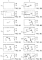
- Figs 2A, 3A, 4A...8A illustrate examples of determining, at a first time t1, a position condition defined in respect of an object 20 that is yet to be included in a sensed image 10. This corresponds to block 102 of Fig 1 .
- the position condition defines when automatic capture of a sensed image occurs.
- Figs 2B, 3B, 4B...8B illustrate examples of automatically capturing, after the first time, a sensed image 10 including a first object 20 not included in the sensed image 10 at the first time t1, in response to an automatic determination that the user-input position condition is now satisfied in respect of the first object 20. This corresponds to block 106 of Fig 1 .
- the position condition defines an entry position where an object 20 enters a sensed image 10. In such cases, it is a necessary condition for satisfaction of the position condition that an object 20, that is to be captured in a sensed image 10, has entered 22 the sensed image 10 via the entry position.
- the entry position may be defined by a user touch input on a touch display displaying the sensed image 10 at the first time t1.
- the sensed image 10 has a perimeter 12, and the entry position 11 is a portion of the perimeter 12.
- the entry position may be a whole of an edge or edges of the perimeter 12 or may be a sub-part or sub-parts of the perimeter 12 or may be a point or points on the perimeter 12.
- the position condition defines a capture position where an object 20, that is yet to be included in the sensed image at the first time, is positioned when automatic capture of the sensed image 10 occurs. It is a necessary condition for satisfaction of the position condition that an object 20, that is to be captured in a sensed image 10, has moved 22 to the capture position. Automatic capture of a sensed image 10 occurs, when the sensed image 10 includes an object 20, not included in the sensed image at the first time t1, that is at the capture position and which satisfies the position condition. The captured image includes an object 20, not included in the sensed image at the first time, that is located at the capture position.
- the capture position may be defined by one or more user touch inputs on a touch display displaying the sensed image 10 at the first time t1.
- the capture position may be defined automatically or manually.
- the capture position may be defined relative to a reference.
- the reference may, for example, be an apparatus-determined reference that is defined relative to the apparatus that senses the image.
- An example of an apparatus-determined reference is a perimeter of the sensed image defined by the image sensor.
- the reference may alternatively be an image-determined reference that is defined relative to the sensed image.
- An example of an image-determined reference is a reference portion of the content of the sensed image.
- the reference portion of the image may be, for example an object.
- the reference portion of the image may be stationary or moving within the sensed image.
- the capture position may be defined in relation to the reference for example distance from the reference or displacement from the reference.
- the capture position may be defined as an absolute position within the sensed image 10 relative to a perimeter of the sensed image 10 or the capture position may be defined as a relative position relative to another object within the sensed image 10.
- an object 20 has satisfied a position condition using image processing algorithms for object detection and tracking.
- the algorithm detects 110 a moving object 20 (a group of contiguous pixels that changes position).
- the detected object 20 may, for example, be an object that has newly entered into the sensed image 10.
- the algorithm tracks 112 the object (the group of contiguous pixels) through the sensed image 10 and can determine when the object has reached a particular position within the sensed image 10 or relative to another object within the sensed image 10.
- Suitable algorithms for detecting and tracking objects are known to the person of ordinary skill in the art.
- the position condition defines an entry position 11 where an object 20 enters a sensed image 10.
- the entry position 11 may be defined by a user touch input on a touch display displaying the sensed image 10 at the first time t1.
- the position condition defines an entry position 11 where an object 20 enters a sensed image 10 and defines a capture position where that object 20 is positioned when automatic capture of the sensed image 10 occurs.
- the entry position 11 may be defined by a user touch input on a touch display displaying the sensed image 10 at the first time t1.
- the capture position may be defined automatically at time t1 in response to defining the entry position 11.
- the capture position 13 is defined as an absolute position 14 within the sensed image 10 relative to a perimeter 12 of the sensed image 10.
- the capture position may be a locus of positions at specified distances from the perimeter 12. In the illustrated example, the locus is a rectangle and automatic capture occurs when the object 20 enters the rectangle.
- the capture position 13 may be a predefined distance, within the sensed image, from a perimeter 12 of the sensed image 10.
- the capture position may be a predetermined distance from the entry point 11.
- the position condition does not define an entry position 11 where an object 20 enters a sensed image 10 but does define a capture position where an object 20 is positioned when automatic capture of the sensed image 10 occurs.
- the capture position 13 may be defined by a user touch input on a touch display displaying the sensed image 10 at the first time t1.
- the capture position 13 is user-defined as an absolute position within the sensed image 10 relative to a perimeter 12 of the sensed image 10.
- the position condition defines an entry position 11 where an object 20 enters a sensed image 10 and defines a capture position 13 where an object 20 is positioned when automatic capture of the sensed image 10 occurs.
- the entry position 11 may be defined by a user touch input on a touch display displaying the sensed image 10 at the first time t1.
- the capture position 13 may be defined by a user touch input on a touch display displaying the sensed image 10 at the first time t1.
- the capture position 13 is defined as an absolute position within the sensed image 10 relative to the entry position 11.
- the position condition does not define an entry position 11 where an object 20 enters a sensed image 10 but does define a capture position where an object 20 is positioned when automatic capture of the sensed image 10 occurs.
- the capture position is user-defined as a relative displacement within the sensed image 10.
- the relative displacement is defined as the position between a user input position P1 and the position P1' of an object 30 that is included in the sensed image 10 at the first time t1.
- the relative displacement is P1'-P1.
- the capture position may be defined by one or more user touch inputs on a touch display displaying the sensed image 10 at the first time t1.
- the user input position P1 may be defined by a user touch input on a touch display displaying the sensed image 10 at the first time t1.
- the position P1' of an object that is included in the sensed image 10 at the first time t1 may be defined by a user touch input on a touch display displaying the sensed image 10 at the first time t1.
- the new object 20 is detected and tracked and, also, the existing object 30 is detected and tracked.
- the position condition defines an entry position 11 1 where an object 20 enters a sensed image 10 and defines a capture position where the object 20 is positioned when automatic capture of the sensed image 10 occurs.
- the capture position is user-defined as a relative displacement within the sensed image 10.
- the relative displacement is defined as the position between a user input position P1 and the position P1' of an object 30 that is included in the sensed image 10 at the first time t1.
- the relative displacement is P1'-P1.
- the capture position may be defined by one or more user touch inputs on a touch display displaying the sensed image 10 at the first time t1.
- the user input position P1 may be defined by a user touch input on a touch display displaying the sensed image 10 at the first time t1.
- the position P1' of an object that is included in the sensed image 10 at the first time t1 may be defined by a user touch input on a touch display displaying the sensed image 10 at the first time t1.
- the user input position P1 may be defined by a user touch input first defining the entry position 11 1 and then tracing the user input, as indicated by the dashed line, to rest at, and define, the user input position P1.
- the new object 20 is detected and tracked and, also, the existing object 30 is detected and tracked.
- the position condition defines a first entry position 11 1 where a first object 20 enters a sensed image 10, defines a second entry position 11 1 ' where a second object 20' enters a sensed image 10, and defines a capture position defining where the first object 20 and the second object 20' are relatively positioned when automatic capture of the sensed image 10 occurs.
- the capture position is user-defined as a relative displacement within the sensed image 10.
- the relative displacement is defined as the position between a user input position P1 (for the first object 20) and a user input position P1' (for the second object 20').
- the relative displacement is P1'-P1.
- the capture position may be defined by one or more user touch inputs on a touch display displaying the sensed image 10 at the first time t1.
- the user input position P1 may be defined by a user touch input on a touch display displaying the sensed image 10 at the first time t1.
- the user input position P1' may be defined by a user touch input on a touch display displaying the sensed image 10 at the first time t1.
- the user input position P1 may be defined by a user touch input first defining the entry position 11 1 (for the first object 20) and then being traced to rest at, and define, the user input position P1 (for the first object 20).
- the user input position P1' may be defined by a user touch input first defining the entry position 11 1 ' (for the second object) and then being traced to rest at, and define, the user input position P1' (for the second object 20').
- Fig 9 illustrates an example of method 200 comprising logic that enables different user-input gestures to determine different position conditions in respect of an object that is yet to be included in a sensed image 10.
- a first gesture is detected the method proceeds to block 204.
- an entry position 11, where an object 20 enters a sensed image 10 is determined based on the first gesture.
- a second gesture is detected the method proceeds to block 208.
- a manual position condition is determined.
- a position condition is automatically determined.
- the position condition may, for example, require the object to move to a particular capture position, dependent upon the first gesture, to trigger automatic capture of a sensed image 10, for example as described previously with respect to Figs 3A and 3B .
- the capture position is defined in respect of an object 20 that is yet to be included in the sensed image 10 and is where automatic capture of a sensed image 10 occurs.
- a relative position condition is automatically determined.
- the position condition may, for example, require the object to move to a particular capture position, dependent upon the relative positions of the second and third gestures, to trigger automatic capture of a sensed image 10, for example as described previously with respect to Figs 7A and 7B or 8A and 8B .
- the capture position is defined in respect of an object that is yet to be included in the sensed image 10 and another object and is where automatic capture of a sensed image 10 occurs.
- a position condition is automatically determined.
- the position condition may, for example, require the object to move to a particular capture position, dependent upon the second gesture, to trigger automatic capture of a sensed image 10, for example as described previously with respect to Figs 5A and 5B .
- the capture position is defined in respect of an absolute position of an object that is yet to be included in the sensed image 10 and is where automatic capture of a sensed image 10 occurs.
- the first gesture may be a user touch input 302 on a touch display 168 displaying the sensed image 10 at the first time t1
- the second gesture may be a user touch input 302 on the touch display 168 displaying the sensed image 10 at the first time t1
- the third gesture may be a trace of a user touch input 302 on the touch display 168 displaying the sensed image 10 at the first time t1.
- a gesture user input is a gesture that has meaning to an apparatus as a user input.
- a gesture may be static or moving.
- a moving gesture may comprise a predetermined movement or a predetermined movement pattern comprising a series of movements.
- a moving gesture may, for example, be an apparatus-independent gesture or an apparatus-dependent gesture.
- An apparatus-independent gesture is decoupled from the user apparatus and involves movement of a user input object 300 e.g. a user body part or parts, or a further apparatus, relative to the user apparatus. The movement may be three dimensional, for example, through a space external to the apparatus.
- the body part may comprise the user's hand or part of the user's hand such as one or more fingers and thumbs.
- the user input object may comprise a different part of the body of the user such as their head.
- An apparatus-dependent gesture involves movement of a user apparatus through space. The movement may be three dimensional. Three-dimensional movement may comprise motion of the user input object 300 in any three orthogonal directions. The motion may comprise the user input object 300 moving towards or away from an apparatus as well as moving in a plane parallel to the apparatus or any combination of such motion.
- a gesture may be a non-contact gesture. A non-contact gesture does not contact the apparatus at any time during the gesture.
- a gesture may be a contact gesture. A contact gesture does contact the apparatus during the gesture.
- a gesture may be an absolute gesture that is defined in terms of an absolute displacement from the user apparatus. Such a gesture may be tethered, in that it is performed at a precise location relative to the apparatus. Alternatively a gesture may be a relative gesture that is defined in terms of relative displacement during the gesture. Such a gesture may be un-tethered, in that it need not be performed at a precise location relative to the apparatus and may be performed at a large number of arbitrary locations.
- a gesture may be defined as evolution of displacement, of a tracked point relative to an origin, with time. It may, for example, be defined in terms of motion using time variable parameters such as displacement, velocity or using other kinematic parameters.
- An un-tethered gesture may be defined as evolution of relative displacement ⁇ d with relative time ⁇ t.
- a gesture may be performed in one dimension (1D gesture), two-dimensions (2D gesture) or three dimensions (3D gesture).
- Any suitable gesture detector may be used to detect a gesture. Examples of suitable detectors include a proximity detector, a touch detector, one or more cameras, for example, stereoscopic cameras, accelerometers, strain gauges or any other suitable means. Many different gestures are possible as gesture user inputs.
- an algorithm detects 110 a moving object.
- the detected object 20 may, for example, be an object that is not yet in the sensed image or has newly entered into the sensed image 10.
- the algorithm tracks 112 the object in space. Suitable algorithms for detecting and tracking objects are known to the person of ordinary skill in the art.
- Detecting and tracking an object outside the sensed image 10 may be achieved using stereoscopic cameras or other techniques for forming depth maps outside the sensed image 10.
- the algorithm tracks 112 the object outside the sensed image 10 and can determine when the object is about to enter the sensed image 10.
- the camera settings may be pre-set for capturing an image comprising the object 20, for example as described in relation to Fig 12 .
- Detecting and tracking an object inside the sensed image 10 may be achieved using image processing. For example, by monitoring changes over time of the pixels of the sensed image 10, the algorithm detects 110 a moving object (a group of contiguous pixels that changes position).
- the detected object 20 may, for example, be an object that has newly entered into the sensed image 10.
- the algorithm tracks 112 the object (the group of contiguous pixels) through the sensed image 10 and can determine when the object has reached a particular position within the sensed image 10 or relative to another object within the sensed image 10.
- Suitable algorithms for detecting and tracking objects are known to the person of ordinary skill in the art.
- the method 100 may further comprise a block 140 as illustrated in Fig 12 .
- camera settings including at least focus, are automatically determined before the first object has been included in the sensed image at time t2. The determined camera settings are then used during automatic capture of the sensed image 10 at block 106.
- the camera settings that are pre-set at block 140 may, for example include auto-focus settings.
- the auto-focus settings may, for example, be such that the object 20, when it enters the sensed image 10 is in sharp focus.
- the auto-focus settings may, for example, be such that the object 20, when it enters the sensed image 10 is in out-of-focus and blurred.
- the camera settings that are pre-set at block 140 may, for example include depth of field as determined by a camera aperture.
- the depth of field may, for example, be such that the object 20, when it enters the sensed image 10, and other objects are in sharp focus.
- the depth of field settings may, for example, be such that the object 20, when it enters the sensed image 10 is outside the depth of field.
- the method 100 may further comprise a block 140 as illustrated in Fig 12 .
- camera settings including at least focus, are automatically adjusted using image data specifically relating specifically to the object 20.
- Fig 13 illustrates a method 131 for enabling the method 100 of Fig 1 and disabling the method 100 of Fig 1 .
- a camera system is operating in a default mode.
- a user starts an object auto-capture mode via a menu or otherwise. This enables the method 100.
- the method 131 After automatic capture of the sensed image 10 at block 106 of the method 100, the method 131 presents a selectable option to the user for exiting the object auto-capture mode and returning to block 130.
- Figs 1 to 13 may be performed by a controller 160 as illustrated in Fig 14 and/or Fig 16 .
- controller 160 may be as controller circuitry.
- the controller 160 may be implemented in hardware alone, have certain aspects in software including firmware alone or can be a combination of hardware and software (including firmware).
- controller 160 may be implemented using instructions that enable hardware functionality, for example, by using executable computer program instructions 154 in a general-purpose or special-purpose processor 150 that may be stored on a computer readable storage medium (disk, memory etc.) to be executed by such a processor 150.
- a general-purpose or special-purpose processor 150 may be stored on a computer readable storage medium (disk, memory etc.) to be executed by such a processor 150.
- the processor 150 is configured to read from and write to the memory 152.
- the processor 150 may also comprise an output interface via which data and/or commands are output by the processor 150 and an input interface via which data and/or commands are input to the processor 150.
- the memory 152 stores a computer program 154 comprising computer program instructions (computer program code) that controls the operation of the apparatus 161 when loaded into the processor 150.
- the computer program instructions, of the computer program 154 provide the logic and routines that enables the apparatus to perform the methods illustrated in any or all of Figs 1 to 13 .
- the processor 150 by reading the memory 152 is able to load and execute the computer program 154.
- the apparatus 161 therefore comprises:
- the computer program 154 may arrive at the apparatus 161 via any suitable delivery mechanism 170.
- the delivery mechanism 170 may be, for example, a non-transitory computer-readable storage medium, a computer program product, a memory device, a record medium such as a compact disc read-only memory (CD-ROM) or digital versatile disc (DVD), an article of manufacture that tangibly embodies the computer program 154.
- the delivery mechanism may be a signal configured to reliably transfer the computer program 154.
- the apparatus 161 may propagate or transmit the computer program 154 as a computer data signal.
- memory 152 is illustrated as a single component/circuitry it may be implemented as one or more separate components/circuitry some or all of which may be integrated/removable and/or may provide permanent/semi-permanent/ dynamic/cached storage.
- processor 150 is illustrated as a single component/circuitry it may be implemented as one or more separate components/circuitry some or all of which may be integrated/removable.
- the processor 150 may be a single core or multi-core processor.
- references to 'computer-readable storage medium', 'computer program product', 'tangibly embodied computer program' etc. or a 'controller', 'computer', 'processor' etc. should be understood to encompass not only computers having different architectures such as single /multi- processor architectures and sequential (Von Neumann)/parallel architectures but also specialized circuits such as field-programmable gate arrays (FPGA), application specific circuits (ASIC), signal processing devices and other processing circuitry.
- References to computer program, instructions, code etc. should be understood to encompass software for a programmable processor or firmware such as, for example, the programmable content of a hardware device whether instructions for a processor, or configuration settings for a fixed-function device, gate array or programmable logic device etc.
- circuitry refers to all of the following:
- circuitry would also cover an implementation of merely a processor (or multiple processors) or portion of a processor and its (or their) accompanying software and/or firmware.
- circuitry would also cover, for example and if applicable to the particular claim element, a baseband integrated circuit or applications processor integrated circuit for a mobile phone or a similar integrated circuit in a server, a cellular network device, or other network device.
- the blocks illustrated in the Figs 1 to 13 may represent steps in a method and/or sections of code in the computer program 154.
- the illustration of a particular order to the blocks does not necessarily imply that there is a required or preferred order for the blocks and the order and arrangement of the block may be varied. Furthermore, it may be possible for some blocks to be omitted.
- Fig 16 illustrates a camera system 161 comprising a controller 160, a camera sensor 164, a touch display 168 and optics 162.
- the camera system may alternatively comprise a display 168 and an alternative gesture detector.
- the controller 160 is configured to display a sensed image 10 detected at the camera sensor 164 on the display 168, which operates as a view finder.
- the controller 160 is configured to control the camera settings of the camera system 161 by, for example, controlling the optics 162 to change the focus settings of the optics and/or change an aperture of the optics.
- the controller 160 is configured to capture a sensed image 10 by storing the sensed image 10 in a data structure within addressable memory 166.
- the camera system161 may, in some examples, be comprised in a different apparatus.
- the camera system 161 may, in some examples, be comprised in a single apparatus.
- this apparatus may be a pocket-sized apparatus suitable for being placed in an inside pocket of a jacket.
- the controller 160 may be configured to perform any one or more of the methods previously described and as illustrated in the preceding figures.
- the controller 160 provides means for processing, at a first time, a user-input to determine a position condition defined in respect of an object that is yet to be included in a sensed image 10.
- the controller 160 provides means for automatically capturing, after the first time, a sensed image 10 including a first object 20 not included in the sensed image 10 at the first time, in response to determination that the user-input position condition is satisfied in respect of the first object 10.
Landscapes
- Engineering & Computer Science (AREA)
- General Engineering & Computer Science (AREA)
- Theoretical Computer Science (AREA)
- Human Computer Interaction (AREA)
- Multimedia (AREA)
- Signal Processing (AREA)
- Physics & Mathematics (AREA)
- General Physics & Mathematics (AREA)
- User Interface Of Digital Computer (AREA)
Claims (14)
- Vorrichtung (161), umfassend:Mittel zum Verarbeiten einer Benutzereingabe, die über Mittel zum Empfangen einer Benutzereingabe empfangen wird, zu einem ersten Zeitpunkt (t1), um eine Aufnahmepositionsbedingung zu bestimmen, die in Bezug auf ein Objekt (20) definiert ist, das noch in ein erfasstes Bild (10) aufzunehmen ist; undMittel zum automatischen Aufnehmen eines erfassten Bildes (10), das ein erstes Objekt (20) enthält, das an dem ersten Zeitpunkt (t1) nicht in dem erfassten Bild (10) enthalten ist, zu einem dritten Zeitpunkt (t3) als Reaktion auf eine Bestimmung, dass die Benutzereingabe-Aufnahmepositionsbedingung durch das erste Objekt (20) erfüllt ist,wobei die Aufnahmepositionsbedingung eine Eintrittsposition definiert, an der ein Objekt (20) in ein erfasstes Bild (10) eintritt, und eine Aufnahmeposition definiert, wobei die Aufnahmeposition entweder manuell gemäß Benutzereingabe oder automatisch definiert wird, wobei es für die automatische Aufnahme eines erfassten Bildes (10) eine notwendige Bedingung ist, dass ein Objekt (20) über die Eintrittsposition zu einem zweiten Zeitpunkt (t2) in das erfasste Bild (10) eingetreten ist und sich zu der Aufnahmeposition bewegt hat, wobei der dritte Zeitpunkt (t3) mit dem zweiten Zeitpunkt (t2) gleichzeitig ist oder nach diesem kommt und wobei das erfasste Bild (10) eine Umgrenzung aufweist und die Eintrittsposition ein Teil der Umgrenzung ist.
- Vorrichtung (161) nach Anspruch 1, wobei die Eintrittsposition durch eine Benutzerberührungseingabe auf einer Berührungsanzeige definiert wird, die das erfasste Bild (10) zu dem ersten Zeitpunkt anzeigt.
- Vorrichtung (161) nach Anspruch 1, wobei die Aufnahmepositionsbedingung auch definiert, wann automatische Aufnahme des erfassten Bildes (10) auftritt.
- Vorrichtung (161) nach Anspruch 1,
wobei die Aufnahmeposition ein vorbestimmter Abstand in dem erfassten Bild (10) von einer Umgrenzung des erfassten Bildes (10) ist oder
wobei die Aufnahmeposition eine benutzerdefinierte absolute Position in dem erfassten Bild (10) ist oder wobei die Aufnahmeposition eine benutzerdefinierte relative Position relativ zu einem anderen Objekt in dem erfassten Bild (10) ist. - Vorrichtung (161) nach Anspruch 1 oder 4,
wobei die Aufnahmeposition durch eine oder mehrere Benutzerberührungseingaben auf einer das erfasste Bild (10) anzeigenden Berührungsanzeige definiert wird. - Vorrichtung (161) nach Anspruch 5,
wobei die Aufnahmeposition ein vordefinierter Abstand in dem erfassten Bild (10) von einer Benutzerberührungseingabe auf einer das erfasste Bild (10) anzeigenden Berührungsanzeige ist; oder
wobei die Aufnahmeposition eine benutzerdefinierte absolute Position ist, die durch eine Benutzerberührungseingabe auf einer das erfasste Bild (10) anzeigenden Berührungsanzeige definiert wird; oder wobei die Aufnahmeposition eine benutzerdefinierte relative Position ist, die durch einen relativen Abstand zwischen zwei oder mehr Benutzerberührungseingaben auf einer das erfasste Bild (10) anzeigenden Berührungsanzeige definiert wird. - Vorrichtung (161) nach einem der vorhergehenden Ansprüche, wobei eine erste Geste die Eintrittsposition definiert, an der ein Objekt (20) in ein erfasstes Bild (10) eintritt, und wobei ein Fehlen einer zweiten Geste automatisch eine Aufnahmeposition definiert, die in Bezug auf das Objekt (20) definiert ist, das noch in das erfasste Bild (10) aufzunehmen ist, an der automatische Aufnahme eines erfassten Bildes (10) auftritt; und wobei eine zweite Geste eine Aufnahmeposition manuell definiert, die in Bezug auf das Objekt (20) definiert ist, das noch in das erfasste Bild (10) aufzunehmen ist, an der automatische Aufnahme eines erfassten Bildes (10) auftritt.
- Vorrichtung (161) nach einem der vorhergehenden Ansprüche, wobei eine erste Geste und eine zweite Geste, die in Bezug auf eine das erfasste Bild (10) anzeigende Anzeige ausgeführt werden, manuell eine erste Position, die die Eintrittsposition ist, und eine zweite Position, die eine Aufnahmeposition ist, definieren, wobei automatische Aufnahme eines erfassten Bildes (10) auftritt, nachdem ein Objekt (20)an der ersten Position in das erfasste Bild (10) eingetreten ist die zweite Position erreicht.
- Vorrichtung (161) nach einem der vorhergehenden Ansprüche, wobei eine erste Geste und eine zweite Geste, die in Bezug auf eine das erfasste Bild (10) anzeigende Anzeige ausgeführt werden, manuell eine erste Position, die einem ersten Objekt (20) zugeordnet ist, das zum ersten Zeitpunkt nicht in dem erfassten Bild (10) enthalten ist, und eine zweite Position, die einem zweiten Objekt zugeordnet ist, das zum ersten Zeitpunkt in dem erfassten Bild (10) enthalten ist, definieren, wobei automatische Aufnahme eines erfassten Bildes (10) auftritt, wenn ein Objekt (20), nachdem es in das erfasste Bild (10) eintritt, eine Position in dem erfassten Bild (10) erreicht, die eine relative Verschiebung von einer Position des zweiten Objekts in dem erfassten Bild (10) aufweist, die gleich einer relativen Verschiebung der ersten Position von der zweiten Position ist.
- Vorrichtung (161) nach einem der vorhergehenden Ansprüche, ausgelegt zum automatischen Bestimmen von Einstellungen, einschließlich mindestens Fokus, bevor das erste Objekt (20) in das erfasste Bild (10) aufgenommen wurde, und zum Verwenden der automatisch bestimmten Einstellung zum Aufnehmen des ersten Bildes.
- Kamerasystem 161, das eine Vorrichtung nach einem der vorhergehenden Ansprüche und einen Kamerasensor 164 umfasst.
- Verfahren, umfassend:Verarbeiten einer Benutzereingabe, die über Mittel zum Empfangen einer Benutzereingabe empfangen wird, zu einem ersten Zeitpunkt (t1), um eine Aufnahmepositionsbedingung zu bestimmen, die in Bezug auf ein Objekt (20) definiert ist, das noch in ein erfasstes Bild (10) aufzunehmen ist;automatisches Aufnehmen eines erfassten Bildes (10), das ein erstes Objekt (20) enthält, das zum ersten Zeitpunkt (t1) nicht in dem erfassten Bild (10) enthalten ist, zu einem dritten Zeitpunkt (t3) als Reaktion auf eine automatische Bestimmung, dass die Benutzereingabe-Aufnahmepositionsbedingung durch das erste Objekt (20) erfüllt ist,wobei die Aufnahmepositionsbedingung eine Eintrittsposition definiert, an der ein Objekt (20) in ein erfasstes Bild (10) eintritt, und eine Aufnahmeposition definiert, wobei die Aufnahmeposition entweder manuell gemäß Benutzereingabe oder automatisch definiert wird,wobei es für die automatische Aufnahme eines erfassten Bildes (10) eine notwendige Bedingung ist, dass ein Objekt (20) über die Eintrittsposition zu einem zweiten Zeitpunkt (t2) in das erfasste Bild (10) eingetreten ist und sich zu der Aufnahmeposition bewegt hat, wobei der dritte Zeitpunkt (t3) mit dem zweiten Zeitpunkt (t2) gleichzeitig ist oder nach diesem kommt und wobei das erfasste Bild (10) eine Umgrenzung aufweist und die Eintrittsposition ein Teil der Umgrenzung ist.
- Verfahren nach Anspruch 12, wobei die Eintrittsposition durch eine Benutzerberührungseingabe auf einer Berührungsanzeige definiert wird, die das erfasste Bild (10) zu dem ersten Zeitpunkt anzeigt.
- Computerprogramm, das, wenn es auf einem oder mehreren Prozessoren einer Vorrichtung mit Mitteln zum Empfangen von Benutzereingaben und Mitteln zum automatischen Aufnehmen erfasster Bilder läuft, bewirkt, dass der eine oder die mehreren Prozessoren ein Verfahren nach mindestens einem der Ansprüche 12 und 13 ausführen.
Priority Applications (2)
| Application Number | Priority Date | Filing Date | Title |
|---|---|---|---|
| EP14188897.4A EP3010225B1 (de) | 2014-10-14 | 2014-10-14 | Verfahren, Vorrichtung und Computerprogramm zur automatischen Erfassung eines Bildes |
| US14/880,655 US9888169B2 (en) | 2014-10-14 | 2015-10-12 | Method, apparatus and computer program for automatically capturing an image |
Applications Claiming Priority (1)
| Application Number | Priority Date | Filing Date | Title |
|---|---|---|---|
| EP14188897.4A EP3010225B1 (de) | 2014-10-14 | 2014-10-14 | Verfahren, Vorrichtung und Computerprogramm zur automatischen Erfassung eines Bildes |
Publications (2)
| Publication Number | Publication Date |
|---|---|
| EP3010225A1 EP3010225A1 (de) | 2016-04-20 |
| EP3010225B1 true EP3010225B1 (de) | 2019-07-24 |
Family
ID=51743302
Family Applications (1)
| Application Number | Title | Priority Date | Filing Date |
|---|---|---|---|
| EP14188897.4A Active EP3010225B1 (de) | 2014-10-14 | 2014-10-14 | Verfahren, Vorrichtung und Computerprogramm zur automatischen Erfassung eines Bildes |
Country Status (2)
| Country | Link |
|---|---|
| US (1) | US9888169B2 (de) |
| EP (1) | EP3010225B1 (de) |
Families Citing this family (2)
| Publication number | Priority date | Publication date | Assignee | Title |
|---|---|---|---|---|
| CN105718887A (zh) * | 2016-01-21 | 2016-06-29 | 惠州Tcl移动通信有限公司 | 基于移动终端摄像头实现动态捕捉人脸摄像的方法及系统 |
| EP3682616B1 (de) * | 2017-09-15 | 2023-11-08 | Kimberly-Clark Worldwide, Inc. | Installationssystem der erweiterten realität für waschraumvorrichtung |
Family Cites Families (40)
| Publication number | Priority date | Publication date | Assignee | Title |
|---|---|---|---|---|
| JPH05196860A (ja) | 1992-01-17 | 1993-08-06 | Kyocera Corp | 予測合焦装置 |
| JP2003189168A (ja) * | 2001-12-21 | 2003-07-04 | Nec Corp | 携帯電話用カメラ |
| US7466356B2 (en) | 2003-07-25 | 2008-12-16 | Hewlett-Packard Development Company, L.P. | Method and apparatus for setting a marker on an object and tracking the position of the object |
| WO2005039174A1 (ja) * | 2003-10-20 | 2005-04-28 | Matsushita Electric Industrial Co., Ltd. | マルチメディアデータ記録装置、モニタシステム、およびマルチメディアデータ記録方法 |
| US20050163345A1 (en) * | 2003-12-03 | 2005-07-28 | Safehouse International Limited | Analysing image data |
| WO2006105655A1 (en) * | 2005-04-06 | 2006-10-12 | March Networks Corporation | Method and system for counting moving objects in a digital video stream |
| US8330866B2 (en) * | 2006-02-21 | 2012-12-11 | Qualcomm Incorporated | Multi-program viewing in a wireless apparatus |
| US8004555B2 (en) * | 2006-05-31 | 2011-08-23 | Motorola Mobility, Inc. | Methods and devices for simultaneous dual camera video telephony |
| KR101373333B1 (ko) * | 2007-07-11 | 2014-03-10 | 엘지전자 주식회사 | 터치인식을 통한 영상촬영 기능을 구비한 휴대 단말기 및그 촬영방법 |
| KR101507797B1 (ko) * | 2008-05-29 | 2015-04-03 | 엘지전자 주식회사 | 단말기 및 그 제어 방법 |
| TW201023633A (en) * | 2008-12-05 | 2010-06-16 | Altek Corp | An image capturing device for automatically position indicating and the automatic position indicating method thereof |
| KR101593573B1 (ko) * | 2009-06-19 | 2016-02-12 | 삼성전자주식회사 | 단말기의 카메라를 이용한 컨텐츠 제작 방법 및 장치 |
| KR101615290B1 (ko) * | 2009-08-26 | 2016-04-26 | 삼성전자주식회사 | 촬영 방법 및 시스템 |
| US20110066924A1 (en) * | 2009-09-06 | 2011-03-17 | Dorso Gregory | Communicating in a computer environment |
| KR101078057B1 (ko) * | 2009-09-08 | 2011-10-31 | 주식회사 팬택 | 영상인식기법을 이용한 촬영 제어 기능을 구비한 이동단말 및 영상인식기법을 이용한 촬영 제어 시스템 |
| EP2393000B1 (de) * | 2010-06-04 | 2019-08-07 | Lg Electronics Inc. | Mobiles Endgerät zur Bereitstellung eines Multiplayer-Spiels und Verfahren zur Steuerung des Betriebs des mobilen Endgeräts |
| JP2012010162A (ja) * | 2010-06-25 | 2012-01-12 | Kyocera Corp | カメラ装置 |
| JP2012049651A (ja) * | 2010-08-24 | 2012-03-08 | Ricoh Co Ltd | 撮像装置及び撮像方法 |
| US9204026B2 (en) * | 2010-11-01 | 2015-12-01 | Lg Electronics Inc. | Mobile terminal and method of controlling an image photographing therein |
| KR101691833B1 (ko) * | 2010-11-04 | 2017-01-09 | 엘지전자 주식회사 | 이동 단말기 및 이것의 영상 촬영 제어 방법 |
| US9584735B2 (en) * | 2010-11-12 | 2017-02-28 | Arcsoft, Inc. | Front and back facing cameras |
| KR101710632B1 (ko) | 2011-03-18 | 2017-02-27 | 삼성전자주식회사 | 자동 초점 조절 장치 |
| KR101758164B1 (ko) * | 2011-04-08 | 2017-07-26 | 엘지전자 주식회사 | 이동 단말기 및 3d 멀티 앵글 뷰 제어방법 |
| US8988558B2 (en) * | 2011-04-26 | 2015-03-24 | Omnivision Technologies, Inc. | Image overlay in a mobile device |
| KR101832959B1 (ko) * | 2011-08-10 | 2018-02-28 | 엘지전자 주식회사 | 휴대 전자기기 및 이의 제어방법 |
| US8866943B2 (en) * | 2012-03-09 | 2014-10-21 | Apple Inc. | Video camera providing a composite video sequence |
| US9503645B2 (en) * | 2012-05-24 | 2016-11-22 | Mediatek Inc. | Preview system for concurrently displaying multiple preview images generated based on input image generated by image capture apparatus and related preview method thereof |
| WO2013175787A1 (ja) * | 2012-05-24 | 2013-11-28 | パナソニック株式会社 | 撮影装置 |
| US9325889B2 (en) * | 2012-06-08 | 2016-04-26 | Samsung Electronics Co., Ltd. | Continuous video capture during switch between video capture devices |
| CN102769775A (zh) * | 2012-06-12 | 2012-11-07 | 严幸华 | 覆盖图像提供系统、服务器和方法 |
| JP6140945B2 (ja) | 2012-07-26 | 2017-06-07 | キヤノン株式会社 | 焦点調節装置及び撮像装置 |
| KR101935039B1 (ko) * | 2012-09-11 | 2019-01-03 | 엘지전자 주식회사 | 이동 단말기 및 이동 단말기의 제어 방법 |
| KR101990036B1 (ko) * | 2012-10-31 | 2019-06-17 | 엘지전자 주식회사 | 이동 단말기 및 그것의 제어 방법 |
| US8953079B2 (en) * | 2012-12-31 | 2015-02-10 | Texas Instruments Incorporated | System and method for generating 360 degree video recording using MVC |
| US20140204263A1 (en) * | 2013-01-22 | 2014-07-24 | Htc Corporation | Image capture methods and systems |
| KR102018887B1 (ko) * | 2013-02-21 | 2019-09-05 | 삼성전자주식회사 | 신체 부위 검출을 이용한 이미지 프리뷰 |
| KR102076771B1 (ko) * | 2013-02-21 | 2020-02-12 | 삼성전자주식회사 | 다수의 이미지 동시 포착 |
| KR102056128B1 (ko) * | 2013-02-28 | 2019-12-17 | 삼성전자 주식회사 | 위젯을 이용한 사진 촬영 방법 및 휴대 장치 |
| US20140240469A1 (en) * | 2013-02-28 | 2014-08-28 | Motorola Mobility Llc | Electronic Device with Multiview Image Capture and Depth Sensing |
| WO2014195924A1 (en) * | 2013-06-07 | 2014-12-11 | Koninklijke Philips N.V. | Visual pre-scan patient information for magnetic resonance protocol |
-
2014
- 2014-10-14 EP EP14188897.4A patent/EP3010225B1/de active Active
-
2015
- 2015-10-12 US US14/880,655 patent/US9888169B2/en active Active
Non-Patent Citations (1)
| Title |
|---|
| None * |
Also Published As
| Publication number | Publication date |
|---|---|
| US20160105602A1 (en) | 2016-04-14 |
| US9888169B2 (en) | 2018-02-06 |
| EP3010225A1 (de) | 2016-04-20 |
Similar Documents
| Publication | Publication Date | Title |
|---|---|---|
| JP6905081B2 (ja) | 車両損失査定画像を取得するための方法および装置、サーバ、ならびに端末デバイス | |
| EP3038345B1 (de) | Autofokusverfahren und autofokusvorrichtung | |
| US9448635B2 (en) | Rapid gesture re-engagement | |
| US20180114067A1 (en) | Apparatus and method for extracting objects in view point of moving vehicle | |
| US9390532B2 (en) | Object removal from an image | |
| CN110650241A (zh) | 移动终端中呈现全景照片的方法和装置、以及移动终端 | |
| JP6494418B2 (ja) | 画像解析装置、画像解析方法、およびプログラム | |
| CN109451240B (zh) | 对焦方法、装置、计算机设备和可读存储介质 | |
| EP3109695B1 (de) | Verfahren und elektronische vorrichtung zum automatischen fokussieren auf ein bewegtes objekt | |
| US9053381B2 (en) | Interaction system and motion detection method | |
| EP3010225B1 (de) | Verfahren, Vorrichtung und Computerprogramm zur automatischen Erfassung eines Bildes | |
| EP3046317A1 (de) | Bildaufnahmeverfahren und -vorrichtung | |
| JP6685742B2 (ja) | 操作装置、移動装置、およびその制御システム | |
| CN106922181B (zh) | 方向感知自动聚焦 | |
| JP2021068208A5 (de) | ||
| US11394873B2 (en) | Control apparatus, control method, and recording medium | |
| US20150281585A1 (en) | Apparatus Responsive To At Least Zoom-In User Input, A Method And A Computer Program | |
| EP3040835B1 (de) | Bildnavigation | |
| EP3239811B1 (de) | Verfahren, vorrichtung oder computerprogramm zur benutzersteuerung des zugriffs auf angezeigte inhalte | |
| US20130016038A1 (en) | Motion detection method and display device | |
| US11991448B2 (en) | Digital zoom | |
| JP2018117191A (ja) | 携帯端末、プログラム、および携帯端末の制御方法 | |
| JP2018006803A (ja) | 撮像装置、撮像装置の制御方法及びプログラム | |
| JP6373541B2 (ja) | ユーザインタフェース装置及びユーザインタフェース方法 | |
| JP2015040939A5 (de) |
Legal Events
| Date | Code | Title | Description |
|---|---|---|---|
| PUAI | Public reference made under article 153(3) epc to a published international application that has entered the european phase |
Free format text: ORIGINAL CODE: 0009012 |
|
| AK | Designated contracting states |
Kind code of ref document: A1 Designated state(s): AL AT BE BG CH CY CZ DE DK EE ES FI FR GB GR HR HU IE IS IT LI LT LU LV MC MK MT NL NO PL PT RO RS SE SI SK SM TR |
|
| AX | Request for extension of the european patent |
Extension state: BA ME |
|
| 17P | Request for examination filed |
Effective date: 20161013 |
|
| RBV | Designated contracting states (corrected) |
Designated state(s): AL AT BE BG CH CY CZ DE DK EE ES FI FR GB GR HR HU IE IS IT LI LT LU LV MC MK MT NL NO PL PT RO RS SE SI SK SM TR |
|
| STAA | Information on the status of an ep patent application or granted ep patent |
Free format text: STATUS: EXAMINATION IS IN PROGRESS |
|
| 17Q | First examination report despatched |
Effective date: 20171025 |
|
| REG | Reference to a national code |
Ref country code: DE Ref legal event code: R079 Ref document number: 602014050383 Country of ref document: DE Free format text: PREVIOUS MAIN CLASS: H04N0005232000 Ipc: G06F0003048800 |
|
| GRAP | Despatch of communication of intention to grant a patent |
Free format text: ORIGINAL CODE: EPIDOSNIGR1 |
|
| STAA | Information on the status of an ep patent application or granted ep patent |
Free format text: STATUS: GRANT OF PATENT IS INTENDED |
|
| RIC1 | Information provided on ipc code assigned before grant |
Ipc: G06F 3/0488 20130101AFI20180702BHEP Ipc: H04N 5/232 20060101ALI20180702BHEP Ipc: G06F 3/0484 20130101ALI20180702BHEP |
|
| INTG | Intention to grant announced |
Effective date: 20180723 |
|
| GRAJ | Information related to disapproval of communication of intention to grant by the applicant or resumption of examination proceedings by the epo deleted |
Free format text: ORIGINAL CODE: EPIDOSDIGR1 |
|
| STAA | Information on the status of an ep patent application or granted ep patent |
Free format text: STATUS: EXAMINATION IS IN PROGRESS |
|
| INTC | Intention to grant announced (deleted) | ||
| GRAP | Despatch of communication of intention to grant a patent |
Free format text: ORIGINAL CODE: EPIDOSNIGR1 |
|
| STAA | Information on the status of an ep patent application or granted ep patent |
Free format text: STATUS: GRANT OF PATENT IS INTENDED |
|
| INTG | Intention to grant announced |
Effective date: 20190221 |
|
| GRAS | Grant fee paid |
Free format text: ORIGINAL CODE: EPIDOSNIGR3 |
|
| GRAA | (expected) grant |
Free format text: ORIGINAL CODE: 0009210 |
|
| STAA | Information on the status of an ep patent application or granted ep patent |
Free format text: STATUS: THE PATENT HAS BEEN GRANTED |
|
| AK | Designated contracting states |
Kind code of ref document: B1 Designated state(s): AL AT BE BG CH CY CZ DE DK EE ES FI FR GB GR HR HU IE IS IT LI LT LU LV MC MK MT NL NO PL PT RO RS SE SI SK SM TR |
|
| REG | Reference to a national code |
Ref country code: GB Ref legal event code: FG4D |
|
| REG | Reference to a national code |
Ref country code: CH Ref legal event code: EP |
|
| REG | Reference to a national code |
Ref country code: DE Ref legal event code: R096 Ref document number: 602014050383 Country of ref document: DE |
|
| REG | Reference to a national code |
Ref country code: AT Ref legal event code: REF Ref document number: 1158988 Country of ref document: AT Kind code of ref document: T Effective date: 20190815 |
|
| REG | Reference to a national code |
Ref country code: IE Ref legal event code: FG4D |
|
| RAP2 | Party data changed (patent owner data changed or rights of a patent transferred) |
Owner name: NOKIA TECHNOLOGIES OY |
|
| REG | Reference to a national code |
Ref country code: NL Ref legal event code: MP Effective date: 20190724 |
|
| REG | Reference to a national code |
Ref country code: LT Ref legal event code: MG4D |
|
| REG | Reference to a national code |
Ref country code: AT Ref legal event code: MK05 Ref document number: 1158988 Country of ref document: AT Kind code of ref document: T Effective date: 20190724 |
|
| PG25 | Lapsed in a contracting state [announced via postgrant information from national office to epo] |
Ref country code: LT Free format text: LAPSE BECAUSE OF FAILURE TO SUBMIT A TRANSLATION OF THE DESCRIPTION OR TO PAY THE FEE WITHIN THE PRESCRIBED TIME-LIMIT Effective date: 20190724 Ref country code: PT Free format text: LAPSE BECAUSE OF FAILURE TO SUBMIT A TRANSLATION OF THE DESCRIPTION OR TO PAY THE FEE WITHIN THE PRESCRIBED TIME-LIMIT Effective date: 20191125 Ref country code: FI Free format text: LAPSE BECAUSE OF FAILURE TO SUBMIT A TRANSLATION OF THE DESCRIPTION OR TO PAY THE FEE WITHIN THE PRESCRIBED TIME-LIMIT Effective date: 20190724 Ref country code: AT Free format text: LAPSE BECAUSE OF FAILURE TO SUBMIT A TRANSLATION OF THE DESCRIPTION OR TO PAY THE FEE WITHIN THE PRESCRIBED TIME-LIMIT Effective date: 20190724 Ref country code: NL Free format text: LAPSE BECAUSE OF FAILURE TO SUBMIT A TRANSLATION OF THE DESCRIPTION OR TO PAY THE FEE WITHIN THE PRESCRIBED TIME-LIMIT Effective date: 20190724 Ref country code: BG Free format text: LAPSE BECAUSE OF FAILURE TO SUBMIT A TRANSLATION OF THE DESCRIPTION OR TO PAY THE FEE WITHIN THE PRESCRIBED TIME-LIMIT Effective date: 20191024 Ref country code: NO Free format text: LAPSE BECAUSE OF FAILURE TO SUBMIT A TRANSLATION OF THE DESCRIPTION OR TO PAY THE FEE WITHIN THE PRESCRIBED TIME-LIMIT Effective date: 20191024 Ref country code: SE Free format text: LAPSE BECAUSE OF FAILURE TO SUBMIT A TRANSLATION OF THE DESCRIPTION OR TO PAY THE FEE WITHIN THE PRESCRIBED TIME-LIMIT Effective date: 20190724 Ref country code: HR Free format text: LAPSE BECAUSE OF FAILURE TO SUBMIT A TRANSLATION OF THE DESCRIPTION OR TO PAY THE FEE WITHIN THE PRESCRIBED TIME-LIMIT Effective date: 20190724 |
|
| PG25 | Lapsed in a contracting state [announced via postgrant information from national office to epo] |
Ref country code: LV Free format text: LAPSE BECAUSE OF FAILURE TO SUBMIT A TRANSLATION OF THE DESCRIPTION OR TO PAY THE FEE WITHIN THE PRESCRIBED TIME-LIMIT Effective date: 20190724 Ref country code: IS Free format text: LAPSE BECAUSE OF FAILURE TO SUBMIT A TRANSLATION OF THE DESCRIPTION OR TO PAY THE FEE WITHIN THE PRESCRIBED TIME-LIMIT Effective date: 20191124 Ref country code: RS Free format text: LAPSE BECAUSE OF FAILURE TO SUBMIT A TRANSLATION OF THE DESCRIPTION OR TO PAY THE FEE WITHIN THE PRESCRIBED TIME-LIMIT Effective date: 20190724 Ref country code: GR Free format text: LAPSE BECAUSE OF FAILURE TO SUBMIT A TRANSLATION OF THE DESCRIPTION OR TO PAY THE FEE WITHIN THE PRESCRIBED TIME-LIMIT Effective date: 20191025 Ref country code: AL Free format text: LAPSE BECAUSE OF FAILURE TO SUBMIT A TRANSLATION OF THE DESCRIPTION OR TO PAY THE FEE WITHIN THE PRESCRIBED TIME-LIMIT Effective date: 20190724 Ref country code: ES Free format text: LAPSE BECAUSE OF FAILURE TO SUBMIT A TRANSLATION OF THE DESCRIPTION OR TO PAY THE FEE WITHIN THE PRESCRIBED TIME-LIMIT Effective date: 20190724 |
|
| PG25 | Lapsed in a contracting state [announced via postgrant information from national office to epo] |
Ref country code: TR Free format text: LAPSE BECAUSE OF FAILURE TO SUBMIT A TRANSLATION OF THE DESCRIPTION OR TO PAY THE FEE WITHIN THE PRESCRIBED TIME-LIMIT Effective date: 20190724 |
|
| PG25 | Lapsed in a contracting state [announced via postgrant information from national office to epo] |
Ref country code: DK Free format text: LAPSE BECAUSE OF FAILURE TO SUBMIT A TRANSLATION OF THE DESCRIPTION OR TO PAY THE FEE WITHIN THE PRESCRIBED TIME-LIMIT Effective date: 20190724 Ref country code: EE Free format text: LAPSE BECAUSE OF FAILURE TO SUBMIT A TRANSLATION OF THE DESCRIPTION OR TO PAY THE FEE WITHIN THE PRESCRIBED TIME-LIMIT Effective date: 20190724 Ref country code: PL Free format text: LAPSE BECAUSE OF FAILURE TO SUBMIT A TRANSLATION OF THE DESCRIPTION OR TO PAY THE FEE WITHIN THE PRESCRIBED TIME-LIMIT Effective date: 20190724 Ref country code: IT Free format text: LAPSE BECAUSE OF FAILURE TO SUBMIT A TRANSLATION OF THE DESCRIPTION OR TO PAY THE FEE WITHIN THE PRESCRIBED TIME-LIMIT Effective date: 20190724 Ref country code: RO Free format text: LAPSE BECAUSE OF FAILURE TO SUBMIT A TRANSLATION OF THE DESCRIPTION OR TO PAY THE FEE WITHIN THE PRESCRIBED TIME-LIMIT Effective date: 20190724 |
|
| PG25 | Lapsed in a contracting state [announced via postgrant information from national office to epo] |
Ref country code: SM Free format text: LAPSE BECAUSE OF FAILURE TO SUBMIT A TRANSLATION OF THE DESCRIPTION OR TO PAY THE FEE WITHIN THE PRESCRIBED TIME-LIMIT Effective date: 20190724 Ref country code: SK Free format text: LAPSE BECAUSE OF FAILURE TO SUBMIT A TRANSLATION OF THE DESCRIPTION OR TO PAY THE FEE WITHIN THE PRESCRIBED TIME-LIMIT Effective date: 20190724 Ref country code: CZ Free format text: LAPSE BECAUSE OF FAILURE TO SUBMIT A TRANSLATION OF THE DESCRIPTION OR TO PAY THE FEE WITHIN THE PRESCRIBED TIME-LIMIT Effective date: 20190724 Ref country code: MC Free format text: LAPSE BECAUSE OF FAILURE TO SUBMIT A TRANSLATION OF THE DESCRIPTION OR TO PAY THE FEE WITHIN THE PRESCRIBED TIME-LIMIT Effective date: 20190724 Ref country code: IS Free format text: LAPSE BECAUSE OF FAILURE TO SUBMIT A TRANSLATION OF THE DESCRIPTION OR TO PAY THE FEE WITHIN THE PRESCRIBED TIME-LIMIT Effective date: 20200224 |
|
| REG | Reference to a national code |
Ref country code: CH Ref legal event code: PL |
|
| REG | Reference to a national code |
Ref country code: DE Ref legal event code: R097 Ref document number: 602014050383 Country of ref document: DE |
|
| PLBE | No opposition filed within time limit |
Free format text: ORIGINAL CODE: 0009261 |
|
| STAA | Information on the status of an ep patent application or granted ep patent |
Free format text: STATUS: NO OPPOSITION FILED WITHIN TIME LIMIT |
|
| PG2D | Information on lapse in contracting state deleted |
Ref country code: IS |
|
| PG25 | Lapsed in a contracting state [announced via postgrant information from national office to epo] |
Ref country code: LU Free format text: LAPSE BECAUSE OF NON-PAYMENT OF DUE FEES Effective date: 20191014 Ref country code: CH Free format text: LAPSE BECAUSE OF NON-PAYMENT OF DUE FEES Effective date: 20191031 Ref country code: LI Free format text: LAPSE BECAUSE OF NON-PAYMENT OF DUE FEES Effective date: 20191031 |
|
| 26N | No opposition filed |
Effective date: 20200603 |
|
| REG | Reference to a national code |
Ref country code: BE Ref legal event code: MM Effective date: 20191031 |
|
| PG25 | Lapsed in a contracting state [announced via postgrant information from national office to epo] |
Ref country code: SI Free format text: LAPSE BECAUSE OF FAILURE TO SUBMIT A TRANSLATION OF THE DESCRIPTION OR TO PAY THE FEE WITHIN THE PRESCRIBED TIME-LIMIT Effective date: 20190724 Ref country code: BE Free format text: LAPSE BECAUSE OF NON-PAYMENT OF DUE FEES Effective date: 20191031 |
|
| GBPC | Gb: european patent ceased through non-payment of renewal fee |
Effective date: 20191024 |
|
| PG25 | Lapsed in a contracting state [announced via postgrant information from national office to epo] |
Ref country code: FR Free format text: LAPSE BECAUSE OF NON-PAYMENT OF DUE FEES Effective date: 20191031 Ref country code: GB Free format text: LAPSE BECAUSE OF NON-PAYMENT OF DUE FEES Effective date: 20191024 Ref country code: IE Free format text: LAPSE BECAUSE OF NON-PAYMENT OF DUE FEES Effective date: 20191014 |
|
| PG25 | Lapsed in a contracting state [announced via postgrant information from national office to epo] |
Ref country code: CY Free format text: LAPSE BECAUSE OF FAILURE TO SUBMIT A TRANSLATION OF THE DESCRIPTION OR TO PAY THE FEE WITHIN THE PRESCRIBED TIME-LIMIT Effective date: 20190724 |
|
| PG25 | Lapsed in a contracting state [announced via postgrant information from national office to epo] |
Ref country code: HU Free format text: LAPSE BECAUSE OF FAILURE TO SUBMIT A TRANSLATION OF THE DESCRIPTION OR TO PAY THE FEE WITHIN THE PRESCRIBED TIME-LIMIT; INVALID AB INITIO Effective date: 20141014 Ref country code: MT Free format text: LAPSE BECAUSE OF FAILURE TO SUBMIT A TRANSLATION OF THE DESCRIPTION OR TO PAY THE FEE WITHIN THE PRESCRIBED TIME-LIMIT Effective date: 20190724 |
|
| PG25 | Lapsed in a contracting state [announced via postgrant information from national office to epo] |
Ref country code: MK Free format text: LAPSE BECAUSE OF FAILURE TO SUBMIT A TRANSLATION OF THE DESCRIPTION OR TO PAY THE FEE WITHIN THE PRESCRIBED TIME-LIMIT Effective date: 20190724 |
|
| P01 | Opt-out of the competence of the unified patent court (upc) registered |
Effective date: 20230527 |
|
| PGFP | Annual fee paid to national office [announced via postgrant information from national office to epo] |
Ref country code: DE Payment date: 20230830 Year of fee payment: 10 |