EP3010140A1 - Electric-vehicle control device - Google Patents
Electric-vehicle control device Download PDFInfo
- Publication number
- EP3010140A1 EP3010140A1 EP14810825.1A EP14810825A EP3010140A1 EP 3010140 A1 EP3010140 A1 EP 3010140A1 EP 14810825 A EP14810825 A EP 14810825A EP 3010140 A1 EP3010140 A1 EP 3010140A1
- Authority
- EP
- European Patent Office
- Prior art keywords
- motor
- rotation angle
- phase
- control
- electric vehicle
- Prior art date
- Legal status (The legal status is an assumption and is not a legal conclusion. Google has not performed a legal analysis and makes no representation as to the accuracy of the status listed.)
- Withdrawn
Links
- 238000012937 correction Methods 0.000 claims abstract description 17
- 230000001133 acceleration Effects 0.000 claims abstract description 12
- 238000006243 chemical reaction Methods 0.000 claims description 35
- 230000001172 regenerating effect Effects 0.000 claims description 28
- 239000003638 chemical reducing agent Substances 0.000 claims description 9
- 238000001514 detection method Methods 0.000 claims description 8
- 230000001934 delay Effects 0.000 claims description 3
- 238000000034 method Methods 0.000 description 16
- 238000010586 diagram Methods 0.000 description 11
- 230000008569 process Effects 0.000 description 10
- 230000008929 regeneration Effects 0.000 description 6
- 238000011069 regeneration method Methods 0.000 description 6
- 230000001360 synchronised effect Effects 0.000 description 4
- 238000012545 processing Methods 0.000 description 3
- 238000004891 communication Methods 0.000 description 2
- 238000012986 modification Methods 0.000 description 2
- 230000004048 modification Effects 0.000 description 2
- 239000004065 semiconductor Substances 0.000 description 2
- 238000004804 winding Methods 0.000 description 2
- 238000010276 construction Methods 0.000 description 1
- 230000000694 effects Effects 0.000 description 1
- 230000004907 flux Effects 0.000 description 1
- 230000007246 mechanism Effects 0.000 description 1
- 230000009467 reduction Effects 0.000 description 1
- 230000001846 repelling effect Effects 0.000 description 1
- 230000004044 response Effects 0.000 description 1
Images



Classifications
-
- B—PERFORMING OPERATIONS; TRANSPORTING
- B60—VEHICLES IN GENERAL
- B60L—PROPULSION OF ELECTRICALLY-PROPELLED VEHICLES; SUPPLYING ELECTRIC POWER FOR AUXILIARY EQUIPMENT OF ELECTRICALLY-PROPELLED VEHICLES; ELECTRODYNAMIC BRAKE SYSTEMS FOR VEHICLES IN GENERAL; MAGNETIC SUSPENSION OR LEVITATION FOR VEHICLES; MONITORING OPERATING VARIABLES OF ELECTRICALLY-PROPELLED VEHICLES; ELECTRIC SAFETY DEVICES FOR ELECTRICALLY-PROPELLED VEHICLES
- B60L7/00—Electrodynamic brake systems for vehicles in general
- B60L7/10—Dynamic electric regenerative braking
- B60L7/14—Dynamic electric regenerative braking for vehicles propelled by AC motors
-
- B—PERFORMING OPERATIONS; TRANSPORTING
- B60—VEHICLES IN GENERAL
- B60L—PROPULSION OF ELECTRICALLY-PROPELLED VEHICLES; SUPPLYING ELECTRIC POWER FOR AUXILIARY EQUIPMENT OF ELECTRICALLY-PROPELLED VEHICLES; ELECTRODYNAMIC BRAKE SYSTEMS FOR VEHICLES IN GENERAL; MAGNETIC SUSPENSION OR LEVITATION FOR VEHICLES; MONITORING OPERATING VARIABLES OF ELECTRICALLY-PROPELLED VEHICLES; ELECTRIC SAFETY DEVICES FOR ELECTRICALLY-PROPELLED VEHICLES
- B60L15/00—Methods, circuits, or devices for controlling the traction-motor speed of electrically-propelled vehicles
- B60L15/02—Methods, circuits, or devices for controlling the traction-motor speed of electrically-propelled vehicles characterised by the form of the current used in the control circuit
- B60L15/025—Methods, circuits, or devices for controlling the traction-motor speed of electrically-propelled vehicles characterised by the form of the current used in the control circuit using field orientation; Vector control; Direct Torque Control [DTC]
-
- B—PERFORMING OPERATIONS; TRANSPORTING
- B60—VEHICLES IN GENERAL
- B60L—PROPULSION OF ELECTRICALLY-PROPELLED VEHICLES; SUPPLYING ELECTRIC POWER FOR AUXILIARY EQUIPMENT OF ELECTRICALLY-PROPELLED VEHICLES; ELECTRODYNAMIC BRAKE SYSTEMS FOR VEHICLES IN GENERAL; MAGNETIC SUSPENSION OR LEVITATION FOR VEHICLES; MONITORING OPERATING VARIABLES OF ELECTRICALLY-PROPELLED VEHICLES; ELECTRIC SAFETY DEVICES FOR ELECTRICALLY-PROPELLED VEHICLES
- B60L7/00—Electrodynamic brake systems for vehicles in general
- B60L7/24—Electrodynamic brake systems for vehicles in general with additional mechanical or electromagnetic braking
- B60L7/26—Controlling the braking effect
-
- H—ELECTRICITY
- H02—GENERATION; CONVERSION OR DISTRIBUTION OF ELECTRIC POWER
- H02P—CONTROL OR REGULATION OF ELECTRIC MOTORS, ELECTRIC GENERATORS OR DYNAMO-ELECTRIC CONVERTERS; CONTROLLING TRANSFORMERS, REACTORS OR CHOKE COILS
- H02P21/00—Arrangements or methods for the control of electric machines by vector control, e.g. by control of field orientation
- H02P21/14—Estimation or adaptation of machine parameters, e.g. flux, current or voltage
- H02P21/18—Estimation of position or speed
-
- H—ELECTRICITY
- H02—GENERATION; CONVERSION OR DISTRIBUTION OF ELECTRIC POWER
- H02P—CONTROL OR REGULATION OF ELECTRIC MOTORS, ELECTRIC GENERATORS OR DYNAMO-ELECTRIC CONVERTERS; CONTROLLING TRANSFORMERS, REACTORS OR CHOKE COILS
- H02P21/00—Arrangements or methods for the control of electric machines by vector control, e.g. by control of field orientation
- H02P21/22—Current control, e.g. using a current control loop
-
- H—ELECTRICITY
- H02—GENERATION; CONVERSION OR DISTRIBUTION OF ELECTRIC POWER
- H02P—CONTROL OR REGULATION OF ELECTRIC MOTORS, ELECTRIC GENERATORS OR DYNAMO-ELECTRIC CONVERTERS; CONTROLLING TRANSFORMERS, REACTORS OR CHOKE COILS
- H02P21/00—Arrangements or methods for the control of electric machines by vector control, e.g. by control of field orientation
- H02P21/50—Vector control arrangements or methods not otherwise provided for in H02P21/00- H02P21/36
-
- H—ELECTRICITY
- H02—GENERATION; CONVERSION OR DISTRIBUTION OF ELECTRIC POWER
- H02P—CONTROL OR REGULATION OF ELECTRIC MOTORS, ELECTRIC GENERATORS OR DYNAMO-ELECTRIC CONVERTERS; CONTROLLING TRANSFORMERS, REACTORS OR CHOKE COILS
- H02P6/00—Arrangements for controlling synchronous motors or other dynamo-electric motors using electronic commutation dependent on the rotor position; Electronic commutators therefor
- H02P6/14—Electronic commutators
- H02P6/15—Controlling commutation time
- H02P6/153—Controlling commutation time wherein the commutation is advanced from position signals phase in function of the speed
-
- H—ELECTRICITY
- H02—GENERATION; CONVERSION OR DISTRIBUTION OF ELECTRIC POWER
- H02P—CONTROL OR REGULATION OF ELECTRIC MOTORS, ELECTRIC GENERATORS OR DYNAMO-ELECTRIC CONVERTERS; CONTROLLING TRANSFORMERS, REACTORS OR CHOKE COILS
- H02P6/00—Arrangements for controlling synchronous motors or other dynamo-electric motors using electronic commutation dependent on the rotor position; Electronic commutators therefor
- H02P6/14—Electronic commutators
- H02P6/16—Circuit arrangements for detecting position
-
- B—PERFORMING OPERATIONS; TRANSPORTING
- B60—VEHICLES IN GENERAL
- B60L—PROPULSION OF ELECTRICALLY-PROPELLED VEHICLES; SUPPLYING ELECTRIC POWER FOR AUXILIARY EQUIPMENT OF ELECTRICALLY-PROPELLED VEHICLES; ELECTRODYNAMIC BRAKE SYSTEMS FOR VEHICLES IN GENERAL; MAGNETIC SUSPENSION OR LEVITATION FOR VEHICLES; MONITORING OPERATING VARIABLES OF ELECTRICALLY-PROPELLED VEHICLES; ELECTRIC SAFETY DEVICES FOR ELECTRICALLY-PROPELLED VEHICLES
- B60L2220/00—Electrical machine types; Structures or applications thereof
- B60L2220/40—Electrical machine applications
- B60L2220/42—Electrical machine applications with use of more than one motor
-
- B—PERFORMING OPERATIONS; TRANSPORTING
- B60—VEHICLES IN GENERAL
- B60L—PROPULSION OF ELECTRICALLY-PROPELLED VEHICLES; SUPPLYING ELECTRIC POWER FOR AUXILIARY EQUIPMENT OF ELECTRICALLY-PROPELLED VEHICLES; ELECTRODYNAMIC BRAKE SYSTEMS FOR VEHICLES IN GENERAL; MAGNETIC SUSPENSION OR LEVITATION FOR VEHICLES; MONITORING OPERATING VARIABLES OF ELECTRICALLY-PROPELLED VEHICLES; ELECTRIC SAFETY DEVICES FOR ELECTRICALLY-PROPELLED VEHICLES
- B60L2220/00—Electrical machine types; Structures or applications thereof
- B60L2220/40—Electrical machine applications
- B60L2220/44—Wheel Hub motors, i.e. integrated in the wheel hub
-
- B—PERFORMING OPERATIONS; TRANSPORTING
- B60—VEHICLES IN GENERAL
- B60L—PROPULSION OF ELECTRICALLY-PROPELLED VEHICLES; SUPPLYING ELECTRIC POWER FOR AUXILIARY EQUIPMENT OF ELECTRICALLY-PROPELLED VEHICLES; ELECTRODYNAMIC BRAKE SYSTEMS FOR VEHICLES IN GENERAL; MAGNETIC SUSPENSION OR LEVITATION FOR VEHICLES; MONITORING OPERATING VARIABLES OF ELECTRICALLY-PROPELLED VEHICLES; ELECTRIC SAFETY DEVICES FOR ELECTRICALLY-PROPELLED VEHICLES
- B60L2220/00—Electrical machine types; Structures or applications thereof
- B60L2220/40—Electrical machine applications
- B60L2220/46—Wheel motors, i.e. motor connected to only one wheel
-
- B—PERFORMING OPERATIONS; TRANSPORTING
- B60—VEHICLES IN GENERAL
- B60L—PROPULSION OF ELECTRICALLY-PROPELLED VEHICLES; SUPPLYING ELECTRIC POWER FOR AUXILIARY EQUIPMENT OF ELECTRICALLY-PROPELLED VEHICLES; ELECTRODYNAMIC BRAKE SYSTEMS FOR VEHICLES IN GENERAL; MAGNETIC SUSPENSION OR LEVITATION FOR VEHICLES; MONITORING OPERATING VARIABLES OF ELECTRICALLY-PROPELLED VEHICLES; ELECTRIC SAFETY DEVICES FOR ELECTRICALLY-PROPELLED VEHICLES
- B60L2240/00—Control parameters of input or output; Target parameters
- B60L2240/10—Vehicle control parameters
- B60L2240/12—Speed
-
- B—PERFORMING OPERATIONS; TRANSPORTING
- B60—VEHICLES IN GENERAL
- B60L—PROPULSION OF ELECTRICALLY-PROPELLED VEHICLES; SUPPLYING ELECTRIC POWER FOR AUXILIARY EQUIPMENT OF ELECTRICALLY-PROPELLED VEHICLES; ELECTRODYNAMIC BRAKE SYSTEMS FOR VEHICLES IN GENERAL; MAGNETIC SUSPENSION OR LEVITATION FOR VEHICLES; MONITORING OPERATING VARIABLES OF ELECTRICALLY-PROPELLED VEHICLES; ELECTRIC SAFETY DEVICES FOR ELECTRICALLY-PROPELLED VEHICLES
- B60L2240/00—Control parameters of input or output; Target parameters
- B60L2240/40—Drive Train control parameters
- B60L2240/42—Drive Train control parameters related to electric machines
- B60L2240/421—Speed
-
- B—PERFORMING OPERATIONS; TRANSPORTING
- B60—VEHICLES IN GENERAL
- B60L—PROPULSION OF ELECTRICALLY-PROPELLED VEHICLES; SUPPLYING ELECTRIC POWER FOR AUXILIARY EQUIPMENT OF ELECTRICALLY-PROPELLED VEHICLES; ELECTRODYNAMIC BRAKE SYSTEMS FOR VEHICLES IN GENERAL; MAGNETIC SUSPENSION OR LEVITATION FOR VEHICLES; MONITORING OPERATING VARIABLES OF ELECTRICALLY-PROPELLED VEHICLES; ELECTRIC SAFETY DEVICES FOR ELECTRICALLY-PROPELLED VEHICLES
- B60L2240/00—Control parameters of input or output; Target parameters
- B60L2240/40—Drive Train control parameters
- B60L2240/42—Drive Train control parameters related to electric machines
- B60L2240/423—Torque
-
- B—PERFORMING OPERATIONS; TRANSPORTING
- B60—VEHICLES IN GENERAL
- B60L—PROPULSION OF ELECTRICALLY-PROPELLED VEHICLES; SUPPLYING ELECTRIC POWER FOR AUXILIARY EQUIPMENT OF ELECTRICALLY-PROPELLED VEHICLES; ELECTRODYNAMIC BRAKE SYSTEMS FOR VEHICLES IN GENERAL; MAGNETIC SUSPENSION OR LEVITATION FOR VEHICLES; MONITORING OPERATING VARIABLES OF ELECTRICALLY-PROPELLED VEHICLES; ELECTRIC SAFETY DEVICES FOR ELECTRICALLY-PROPELLED VEHICLES
- B60L2240/00—Control parameters of input or output; Target parameters
- B60L2240/40—Drive Train control parameters
- B60L2240/52—Drive Train control parameters related to converters
- B60L2240/526—Operating parameters
-
- B—PERFORMING OPERATIONS; TRANSPORTING
- B60—VEHICLES IN GENERAL
- B60L—PROPULSION OF ELECTRICALLY-PROPELLED VEHICLES; SUPPLYING ELECTRIC POWER FOR AUXILIARY EQUIPMENT OF ELECTRICALLY-PROPELLED VEHICLES; ELECTRODYNAMIC BRAKE SYSTEMS FOR VEHICLES IN GENERAL; MAGNETIC SUSPENSION OR LEVITATION FOR VEHICLES; MONITORING OPERATING VARIABLES OF ELECTRICALLY-PROPELLED VEHICLES; ELECTRIC SAFETY DEVICES FOR ELECTRICALLY-PROPELLED VEHICLES
- B60L2260/00—Operating Modes
- B60L2260/20—Drive modes; Transition between modes
- B60L2260/28—Four wheel or all wheel drive
-
- H—ELECTRICITY
- H02—GENERATION; CONVERSION OR DISTRIBUTION OF ELECTRIC POWER
- H02P—CONTROL OR REGULATION OF ELECTRIC MOTORS, ELECTRIC GENERATORS OR DYNAMO-ELECTRIC CONVERTERS; CONTROLLING TRANSFORMERS, REACTORS OR CHOKE COILS
- H02P2205/00—Indexing scheme relating to controlling arrangements characterised by the control loops
- H02P2205/05—Torque loop, i.e. comparison of the motor torque with a torque reference
-
- Y—GENERAL TAGGING OF NEW TECHNOLOGICAL DEVELOPMENTS; GENERAL TAGGING OF CROSS-SECTIONAL TECHNOLOGIES SPANNING OVER SEVERAL SECTIONS OF THE IPC; TECHNICAL SUBJECTS COVERED BY FORMER USPC CROSS-REFERENCE ART COLLECTIONS [XRACs] AND DIGESTS
- Y02—TECHNOLOGIES OR APPLICATIONS FOR MITIGATION OR ADAPTATION AGAINST CLIMATE CHANGE
- Y02T—CLIMATE CHANGE MITIGATION TECHNOLOGIES RELATED TO TRANSPORTATION
- Y02T10/00—Road transport of goods or passengers
- Y02T10/60—Other road transportation technologies with climate change mitigation effect
- Y02T10/64—Electric machine technologies in electromobility
Definitions
- Patent Document 2 a technique to correct a delay in control timing, thereby allowing a motor to be accurately controlled is proposed (Patent Document 2).
- a permanent magnet synchronous motor (PM motor) is used as a drive source, and a vector control device is used for controlling rotary drive of the PM motor.
- current command values O_Id and O_Iq two-phase current command values for a motor current are calculated on the basis of a torque command T, an actual current is detected, and three-phase currents are applied to the motor in order to cause the actual current to coincide with a command current.
- Flow of the control is as follows.
- a current PI control section 41 calculates control variables Vdc and Vqc as voltage values in the PI control on the basis of the values of the d-axis current O_Id and the q-axis current O_Iq outputted from the current command section 40 and of two-phase currents Id' and Iq' resulting from adjustment, by the control parameter adjustment section 34, of two-phase currents Id and Iq which are calculated by a three phase/two phase conversion section 42 on the basis of the motor current and the rotor angle.
- Fig. 5 is a diagram representing an image for deriving calculation formulas in the case that the rotor of the motor shifts from an angle A0 (electrical angle) toward an angle B0 (electrical angle).
- Angle A0 (electrical angle) is indicated as ⁇ _A0.
- Angle B0 (electrical angle) is indicated as ⁇ _B0.
- ⁇ is an angular speed of the rotor electrical angle (an angular speed at a time when the rotor starts from the angle A0).
- t_A0 is a time when the rotor starts from the angle A0.
- t_B0 is a time when the rotor arrives at the angle B0.
Landscapes
- Engineering & Computer Science (AREA)
- Power Engineering (AREA)
- Transportation (AREA)
- Mechanical Engineering (AREA)
- Physics & Mathematics (AREA)
- Electromagnetism (AREA)
- Control Of Ac Motors In General (AREA)
- Electric Propulsion And Braking For Vehicles (AREA)
- Control Of Motors That Do Not Use Commutators (AREA)
Abstract
Description
- This application is based on and claims Convention priority to
Japanese patent application No. 2013-124312, filed June 13, 2013 - The present invention relates to a control device for an electric vehicle, and relates to, for example, a technique to correct a rotor phase (electrical angle) at the time of calculation in vector control in accordance with a command torque by using an angular speed of a rotor electrical angle and differential of the angular speed of the electrical angle, during power running control of a motor and during regenerative control of the motor.
- As an electric vehicle, a vehicle including left and right wheels as drive wheels which are driven by respective independent traction motors is publicly known (Patent Document 1). Rotation of each motor is transmitted to the corresponding wheel via a reducer or reduction gear and a wheel bearing. As each motor, for example, an IPM motor (interior permanent magnet synchronous motor) is used.
-
- [Patent Document 1]
JP Laid-open Patent Publication No. 2012-178919 - [Patent Document 2]
JP Laid-open Patent Publication No. 2004-40906 - Regarding a method for controlling an IPM motor, a rotation angle is detected by a motor rotation angle sensor with an interrupt function running on a CPU, and three-phase currents are supplied to the IPM motor on the basis of the detected rotation angle, thereby controlling the motor. However, a rotation angle deviation due to the difference between take-in times occurs between a rotation angle of a rotor at a time when three-phase currents (Iu, Iv, Iw) are detected (time t_A) and a rotation angle of the rotor at a time when the rotation angle (electrical angle) of the rotor is detected (time t_B). There is a problem that, due to the above deviation between the two rotation angles, the motor cannot be accurately controlled. This problem will be described in detail below.
- First, t_A, t_B, t_C, Θ_A, Θ B, and Θ_C are defined mentioned below.
- t_A: the time when the three-phase currents (Iu, Iv, Iw) are detected.
- t_B: the time when the rotation angle (electrical angle) of the rotor is acquired.
- t_C: a time when three-phase command voltages (Vu, Vv, Vw) are applied to the motor.
- Θ_A: a phase (electrical angle) of the rotor at the time when the three-phase currents (Iu, Iv, Iw) are detected.
- Θ_B: a phase (electrical angle) of the rotor at the time when the rotation angle (electrical angle) of the rotor is acquired.
- Θ_C: a phase (electrical angle) of the rotor at the time when the three-phase command voltages (Vu, Vv, Vw) are applied to the motor.
- The t_A, t_B, and t_C are times of calculation of the CPU, which are measured and set in advance.
- With the interrupt function running on the CPU, the three-phase currents (Iu, Iv, Iw) are detected at t_A, and the rotation angle (electrical angle) of the rotor is detected at t_B. On the basis of these detection values, the detected three-phase currents are converted into two-phase currents. However, there is a characteristic that the three-phase currents (Iu, Iv, Iw) and the rotation angle (electrical angle) of the rotor cannot be detected with the interrupt function running on the CPU at the same time, and an angle of the rotor at the time when the detected three-phase currents are converted into the two-phase currents is not equal to the angle at t_A.
- In addition, two-phase command voltages are generated in PI control on the basis of the acquired two-phase currents, and coordinate conversion from the generated two-phase command voltages into three-phase command voltages (Vu, Vv, Vw) is performed. Thereafter, the three-phase command voltages (Vu, Vv, Vw) generated are applied to the motor at t_C. But there is a problem that as the rotation angle (electrical angle) of the rotor at t_C, the rotation angle acquired at t_B is used, and thus the motor cannot be accurately controlled.
- For example, in the following conventional art, a technique to correct a delay in control timing, thereby allowing a motor to be accurately controlled is proposed (Patent Document 2). In an electric vehicle according to this conventional art, a permanent magnet synchronous motor (PM motor) is used as a drive source, and a vector control device is used for controlling rotary drive of the PM motor. In this control method, current command values O_Id and O_Iq (two-phase current command values) for a motor current are calculated on the basis of a torque command T, an actual current is detected, and three-phase currents are applied to the motor in order to cause the actual current to coincide with a command current. Flow of the control is as follows.
- (1) A motor current detection process (a rotor phase is θ1)
- (2) A phase detection process (a rotor phase is θ2)
- (3) A process of coordinate conversion of the detected current (from three phase into two phase)
- (4) A current control PI calculation process
- (5) A process of coordinate conversion for generating command voltage (from two phase into three phase)
- (6) Application of the command voltage to motor (a rotor phase is θ6)
- In the method, the above rotor phase θ1 and rotor phase θ6 are calculated on the basis of the detected rotor phase θ2, a difference in calculation time, and a rotation speed of the motor at this time, whereby the motor can be accurately controlled. However, in this conventional art, during rapid acceleration or rapid deceleration of the motor, an error of a value for correcting a delay in control timing increases, resulting in a problem that the motor cannot be accurately controlled.
- An object of the present invention is to provide a control device for an electric vehicle which control device is able to accurately control a traction motor of the electric vehicle without any delay in control timing during rapid acceleration or rapid deceleration of the motor.
- Hereinafter, in order to facilitate understanding of the present invention, the present invention will be described with reference to the reference numerals in embodiments for the sake of convenience.
- A
motor 6 may drive either one or both of afront wheel 3 and arear wheel 2 of the vehicle and may constitute a part of an in-wheelmotor drive device 8 which includes themotor 6, a wheel bearing 4, and areducer 7. - Any combination of at least two constructions, disclosed in the appended claims and/or the specification and/or the accompanying drawings should be construed as included within the scope of the present invention. In particular, any combination of two or more of the appended claims should be equally construed as included within the scope of the present invention.
- In any event, the present invention will become more clearly understood from the following description of preferred embodiments thereof, when taken in conjunction with the accompanying drawings. However, the embodiments and the drawings are given only for the purpose of illustration and explanation, and are not to be taken as limiting the scope of the present invention in any way whatsoever, which scope is to be determined by the appended claims. In the accompanying drawings, like reference numerals are used to denote like parts throughout the several views, and:
-
Fig. 1 is a block diagram of a schematic configuration showing an electric vehicle according to a first embodiment of the present invention in a plan view; -
Fig. 2 is a block diagram of a schematic configuration of an inverter device and the like of the electric vehicle; -
Fig. 3A is a schematic configuration diagram of an IPM motor of the electric vehicle; -
Fig. 3B is a diagram illustrating an example where a primary current flowing to the IPM motor is split into a d-axis current and a q-axis current; -
Fig. 4 is a block diagram of a motor control module of the electric vehicle including a torque control system; -
Fig. 5 is a diagram representing an image for deriving calculation formulas when the rotor of the motor shifts from an angle A0 toward an angle B0; and -
Fig. 6 is a flowchart for adjustment of the rotor rotation angle (phase) of the motor. - A control device for an electric vehicle according to a first embodiment of the present invention will be described with reference to
Figs. 1 to 6 .Fig. 1 is a block diagram of a schematic configuration showing the electric vehicle according to the embodiment in a plan view. As shown inFig. 1 , the electric vehicle is a four-wheel vehicle which includes avehicle body 1 with left and rightrear wheels 2 as drive wheels and with left and rightfront wheels 3 as driven wheels which are steering wheels. Thedrive wheels 2 and the drivenwheels 3 are both equipped with tires and are supported by thevehicle body 1 viarespective wheel bearings - In
Fig. 1 , thewheel bearings right drive wheels independent traction motors motor 6 is transmitted via areducer 7 and thewheel bearing 4 to thecorresponding wheel 2. Themotor 6, thereducer 7, and thewheel bearing 4 are integrally assembled with each other to form an in-wheelmotor drive device 8. The in-wheelmotor drive device 8 is partly or entirely disposed within thewheel 2. Thereducer 7 is composed of, for example, a cycloidal reducer. Thewheels electromechanical brakes steering wheels portion 12 such as a steering wheel. -
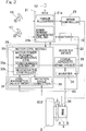
Fig. 2 is a block diagram of a schematic configuration of an inverter device and the like of the electric vehicle. As shown inFig. 2 , the electric vehicle includes anECU 21 which is an electric control unit configured to perform general control of the vehicle, and aninverter device 22 configured to perform control of thetraction motors 6 according to commands from theECU 21. TheECU 21 includes a computer, programs which are executed by the computer, and various electronic circuits. TheECU 21 includes atorque allocation section 21a and a power running/regenerativecontrol command section 21b. - The
torque allocation section 21a is configured to generate an accelerating/decelerating command as a torque command value, which is to be sent to thetraction motors right wheels accelerator manipulation portion 16, a decelerating command outputted from abrake manipulation portion 17, and a cornering command from the steeringportion 12, and to output the accelerating/decelerating command to eachinverter device 22. Thetorque allocation section 21a has a function to, in response to the decelerating command outputted from thebrake manipulation portion 17, generate a braking torque command value allocated to regenerative braking of themotor 6 and a braking torque command value allocated to the operation of theelectromechanical brakes motors right wheels brakes brake controller 23. - The power running/regenerative
control command section 21b is configured to send a command flag configured to switch between acceleration (power running) and deceleration (regeneration), to a motor power running/regenerative control section 33 of amotor control module 29 described later. - The
inverter device 22 includes apower circuitry 28 provided for eachmotor 6, and themotor control module 29 configured to control thepower circuitry 28. Thepower circuitry 28 includes aninverter 31 configured to convert a DC power from abattery 19 into a three-phase AC power used for power running and regeneration of themotor 6, and aPWM driver 32 configured to control theinverter 31. Themotor 6 is composed of a three-phase synchronous motor or the like. Themotor 6 is provided with arotation angle sensor 36 configured to detect a rotation angle as an electrical angle of a rotor of the motor. Theinverter 31 includes a plurality of semiconductor switching elements, and thePWM driver 32 performs pulse width modulation according to an inputted current command and sends an ON/OFF command to each of the semiconductor switching elements. - The
motor control module 29 includes a computer, programs which are executed by the computer, and various electronic circuits. Themotor control module 29 includes the motor power running (drive)/regenerative control section 33 as a basic control section. The motor power running/regenerative control section 33 is configured to perform conversion into a current command in accordance with the accelerating (power running)/decelerating (regeneration) command such as the torque command sent from theECU 21, which is primary control unit, and to send the current command to thePWM driver 32 of thepower circuitry 28. Switching between acceleration (power running) and deceleration (regeneration) is performed on the basis of the command flag from the power running/regenerativecontrol command section 21b of theECU 21. The motor power running/regenerative control section 33 includespower running controller 33a andregenerative controller 33b, and either thepower running controller 33a or theregenerative controller 33b is selectively used on the basis of the command flag from the power running/regenerativecontrol command section 21b. - The motor power running/
regenerative control section 33 generates a command current value to themotor 6, on the basis of the command flag, by using a torque map which is preset in the inverter. The motor power running/regenerative control section 33 detects a value of current which actually flows through themotor 6 in this case, and controls themotor 6 through PI control in order to match the current value with the command current. - The
motor control module 29 also includes a controlparameter adjustment section 34 and a rotation angle (phase)correction section 38. The controlparameter adjustment section 34 adjusts a PI control gain which is used in controlling themotor 6. Meanwhile, the rotation angle (phase)correction section 38 acquires the rotation angle as the electrical angle of the rotor of themotor 6 from therotation angle sensor 36, and corrects the rotation angle as described later, whereby vector control can be realized with high accuracy. - In the present embodiment, signal communication among the
ECU 21, theinverter device 22, thebrake controller 23, and the steeringportion 12 is performed with controller area network (CAN) communication. -
Fig. 3A shows a schematic configuration diagram of an IPM motor of the electric vehicle. As shown inFig. 3A , in the case where the motor which drives the wheel is an IPM motor, that is, an interior magnet synchronous motor, a magnetic resistance in the direction of a q-axis orthogonal to a d-axis which is a magnet axis of the rotor is lower than that in the direction of the d-axis, thus the rotor has a salient pole structure, and a q-axis inductance Lq becomes higher than a d-axis inductance Ld. Depending on the salient structure, a reluctance torque Tr can be used in addition to a magnetic torque Tm, so that a high torque and high efficiency can be achieved. The magnet torque Tm is a torque generated by attraction and repelling between a magnetic field generated by a permanent magnet of a rotor and a rotating magnetic field generated by a winding. The reluctance torque Tr is a torque generated by a salient pole portion of the rotor being attracted to the rotating magnetic field generated by the winding. - A total torque generated by the motor is as follows.

- p: the number of pole pairs
- Ld: the d-axis inductance of the motor
- Lq: the q-axis inductance of the motor
- Ke: an effective value of a motor induced voltage constant
- A vector control method is well-known in which, as shown in
Fig. 3B , a primary current Ia flowing to the IPM motor is split into a q-axis current Iq which is a torque generation current and a d-axis current Id which is a magnetic flux generation current, and the q-axis current Iq and the d-axis current Id can be independently controlled.

- β: a current advance angle
-
Fig. 4 is a block diagram including a torque control system of themotor control module 29 of the electric vehicle. A description will be given also with reference toFig. 2 . Themotor control module 29 is configured to control a motor drive current and includes acurrent command section 40. Thecurrent command section 40 generates an appropriate command current by using the torque map which is preset in the inverter of theinverter device 22, on the basis of a detection value of a drive current which is applied to themotor 6 and is detected by therotation angle sensor 36 and of a torque command value which is the accelerating/decelerating command generated by thetorque allocation section 21a of theECU 21. That is, thecurrent command section 40 performs PI feedback control for eliminating a deviation relative to the command current value generated in the inverter, in accordance with the torque command value from theECU 21. The direction of the command current (the sign of the command current) is switched on the basis of the command flag sent from the power running/regenerativecontrol command section 21b of theECU 21. - The motor power running/
regenerative control section 33 acquires the rotation angle of the rotor of themotor 6 from therotation angle sensor 36 and performs vector control. Between themotors 6 provided to the left and rightrear wheels motor 6 is seen from the direction of an output shaft thereof, themotor 6 for driving the left rear wheel generates a torque in the CW direction, and themotor 6 for driving the right rear wheel generates a torque in the CCW direction (the left and right sides are determined by the direction in which the vehicle is seen from the rear side). So the each torque generated by the correspondingmotors 6 at the left and right sides is transmitted, via thereducer 7 and thewheel bearing 4, to the tire while the direction of one torque is reversed relative to the other torque. In addition, the torque generation directions during regeneration in themotors 6 at the left and right tires are different from the torque generation directions during power running, in the opposite relationship to each other. - Regarding the torque map, an appropriate torque command value is calculated from a maximum torque control table on the basis of an accelerating signal and the rotation speed of the
motor 6. Thecurrent command section 40 generates command values of the primary current (Ia) and the current advance angle (β) of themotor 6 on the basis of the calculated torque command value. Thecurrent command section 40 generates two command currents, a d-axis current (magnetic field component) O_lid and a q-axis current O_Iq on the basis of the values of the primary current (Ia) and the current advance angle (β). - A current
PI control section 41 calculates control variables Vdc and Vqc as voltage values in the PI control on the basis of the values of the d-axis current O_Id and the q-axis current O_Iq outputted from thecurrent command section 40 and of two-phase currents Id' and Iq' resulting from adjustment, by the controlparameter adjustment section 34, of two-phase currents Id and Iq which are calculated by a three phase/twophase conversion section 42 on the basis of the motor current and the rotor angle. The three phase/twophase conversion section 42 calculates a v-phase current (Iv), which is obtained by the following equation, Iv = -(Iu + Iw), on the basis of detection values of a u-phase current (Iu) and a w-phase current (Iw) of themotor 6 which are detected by current sensors (motor current detection portion) 43 which detect each motor current, and converts the three-phase currents Iu, Iv, and Iw into two-phase currents Id and Iq. The rotor angle of themotor 6 used for this conversion is obtained from therotation angle sensor 36. The detected value of the rotation angle (phase) is corrected by the rotation angle (phase)correction section 38, whereby themotor 6 can be accurately controlled. - A two phase/three
phase conversion section 44 converts the inputted two-phase control variables Vdc and Vqc, by use of the value corrected by the rotation angle (phase)correction section 38, into three-phase PWM duties Vu, Vv, and Vw. Apower conversion section 45 corresponds to thepower circuitry 28 inFig. 2 , performs PWM control of theinverter 31 in accordance with the PWM duties Vu, Vv, and Vw, and drives themotor 6. -
Fig. 5 is a diagram representing an image for deriving calculation formulas in the case that the rotor of the motor shifts from an angle A0 (electrical angle) toward an angle B0 (electrical angle). Angle A0 (electrical angle) is indicated as Θ_A0. Angle B0 (electrical angle) is indicated as Θ_B0. ω is an angular speed of the rotor electrical angle (an angular speed at a time when the rotor starts from the angle A0). t_A0 is a time when the rotor starts from the angle A0. t_B0 is a time when the rotor arrives at the angle B0. - In the case of shift from the angle A0 toward the angle B0, a rotation state can be divided into three
rotation states - [Rotation state 1] The rotor rotates at a constant speed.
A calculation formula for the angle B0 is established as follows (a solid line inFig. 5 ).
- [Rotation state 2] The rotor rotates while accelerating (a broken line in
Fig. 5 ).
Since the value of dω/dt is positive, + 1/2 × dω/dt × (t_B0 - t_A0)^2 is an angle component which advances due to the acceleration. - [Rotation state 3] The rotor rotates while decelerating (a dotted line in
Fig. 5 ).
Angle B0 (electrical angle) is obtained by the same formula in therotation state 2.
Since the value of dω/dt is negative, + 1/2 × dω/dt × (t_B0 - t_AO)^2 is an angle component which delays due to the deceleration. -
Fig. 6 is a flowchart for adjustment of the rotor rotation angle (phase) of the motor. This flowchart is executed with an interrupt function running on a CPU at regular time intervals. After this process starts, an accelerating signal is taken in, and current command values are generated (step S1). Next, a process of detecting three-phase currents of the motor is performed, the rotor phase at this time is denoted by Θ_A, and the processing time at this time is denoted by t_A (step S2). Subsequently, a rotor rotation angle (phase) is detected (step S3). The rotor phase at this time is denoted by Θ_B, and the processing time at this time is denoted by t_B. - Next, the process proceeds to step S4, and coordinate conversion from the detected three-phase currents (Iu, Iv, Iw) into two-phase currents (Id, Iq) is performed. Coordinate conversion formulas from the detected three-phase currents into the two-phase currents in this case are the following coordinate conversion formulas.


The current Iw is obtained by a formula, Iw = -(Iu + Iv). - The above Θ is calculated by the rotation angle (phase) correction section 38 (
Fig. 2 ) on the basis of the followingphase correction formula 1.
- In the case of performing power running control, the value of dω/dt is positive.
- In the case of performing regenerative control, the value of dω/dt is negative.
- The ω and the dω/dt are calculated with another interrupt function.
- PI calculation in control of the two-phase currents is performed by the current PI control section 41 (
Fig. 4 ) to generate two-phase command voltages (Vd, Vq) (step S5). Subsequently, coordinate conversion from the two-phase command voltages (Vd, Vq) into three-phase command voltages (Vu, Vv, Vw) is performed (step S6). Coordinate conversion formulas from the two-phase command voltages into the three-phase command voltages in this case are the following coordinate conversion formulas.


(Vd: d-axis voltage, Vq: q-axis voltage) - The above Θ is calculated by the rotation angle (phase) correction section 38 (
Fig. 2 ) on the basis of the followingphase correction formula 2.
- In the case of performing power running control, the value of dω/dt is positive.
- In the case of performing regenerative control, the value of dω/dt is negative.
- Next, the process proceeds to step S7, and the three-phase command voltages are applied to the motor. The rotor phase at this time is denoted by Θ_C, and the processing time is denoted by t_C. Thereafter, the process is ended.
- Functions and advantageous effects will now be described. The
motor control module 29 controls thepower circuitry 28 on the basis of the accelerating/decelerating command, which is the torque command or the like sent from theECU 21, and performs torque control of output of themotor 6. The rotation angle of themotor 6 is detected by therotation angle sensor 36 and is used for vector control. The rotationangle correction section 38 of themotor control module 29 corrects the rotation angle of the rotor of themotor 6 in accordance with the torque command from theECU 21 by using the angular speed ω of the electrical angle, which is the rotation angle detected by therotation angle sensor 36, and the differential value dω/dt of this electrical angle. - When, as in the conventional art, the rotation angle of the motor is corrected by using the angular speed of the electrical angle alone which is the detected rotation angle of the motor, an error of a value for correcting a delay in control timing during rapid acceleration or rapid deceleration of the motor increases, so that the motor cannot be accurately controlled. In this embodiment, the rotation angle of the
motor 6 is corrected by using not only the angular speed ω of the electrical angle but also the differential value dω/dt of the angular speed of the electrical angle, whereby no delay in control timing even during rapid acceleration or rapid deceleration of themotor 6 occurs, and themotor 6 can be accurately controlled. When themotor 6 rotates at a constant speed, the rotationangle correction section 38 can accurately control the rotation angle of themotor 6 without taking the differential value dω/dt of the angular speed of the electrical angle into consideration, that is, by using the angular speed ω of the electrical angle alone. - The three phase/two
phase conversion section 42 converts the three-phase currents (Iu, Iv, Iw) flowing to themotor 6 into the two-phase currents (Id, Iq) on the basis of the coordinate conversion formulas. In the coordinate conversion formulas, a term that takes the differential value dω/dt of the angular speed of the electrical angle into consideration, that is, 1/2 × dω/dt × (t_B - t_A)^2, is put, whereby the rotation angle which is the electrical angle of the rotor of themotor 6 can be accurately corrected regardless of being during acceleration or deceleration of themotor 6. - Also, the two phase/three
phase conversion section 44 converts the two-phase command voltages (Vd, Vq) into the three-phase command voltages (Vu, Vv, Vw) on the basis of the coordinate conversion formulas. In the coordinate conversion formulas, a term that takes the differential value dω/dt of the angular speed of the electrical angle into consideration, that is, 1/2 × dω)/dt × (t_C - t_B)^2, is put, whereby the rotation angle which is the electrical angle of the rotor of themotor 6 can be accurately corrected regardless of being during acceleration or deceleration of themotor 6. - The present invention is also applicable to an electric vehicle whose wheels are driven by motors disposed outside the wheels, such as an on-board type, in addition to an in-wheel motor type, as a type in which wheels are driven by respective motors. Furthermore, the present invention is also applicable to an electric vehicle whose four wheels are driven by respective motors, or an electric vehicle whose wheels are driven for running by a single motor.
- Although the preferred embodiments of the present invention has been fully described with reference to the accompanying drawings which are used only for the purpose of illustration, those skilled in the art will readily conceive numerous changes and modifications within the framework of obviousness upon the reading of the specification herein presented of the present invention. Accordingly, such changes and modifications are, unless they depart from the scope of the present invention as delivered from the claims annexed hereto, to be construed as included within the scope.
-
- 2,3
- wheel
- 4
- wheel bearing
- 6
- motor
- 7
- reducer
- 8
- in-wheel motor drive device
- 21
- ECU
- 22
- inverter device
- 28
- power circuitry
- 29
- motor control module
- 31
- inverter
- 33a
- power running controller
- 33b
- regenerative controller
- 36
- rotation angle sensor
- 38
- rotation angle correction section
- 42
- three phase/two phase conversion section
- 44
- two phase/three phase conversion section
Claims (6)
- A control device for an electric vehicle, comprising:an ECU which is an electric control unit configured to perform general control of the vehicle;an inverter device including: a power circuitry having an inverter configured to convert a DC power into an AC power used to drive a traction motor; and a motor control module configured to control the power circuitry in accordance with a torque command from the ECU; anda rotation angle sensor configured to detect a rotation angle of the motor, whereinthe motor control module acquires a rotation angle of a rotor of the motor from the rotation angle sensor and performs a vector control, andthe motor control module comprises a rotation angle correction section configured to correct the rotation angle of the rotor of the motor which is detected by the rotation angle sensor and used for the vector control, by using an angular speed of an electrical angle which is the rotation angle detected by the rotation angle sensor and a differential value of the angular speed of this electrical angle.
- The control device for the electric vehicle as claimed in claim 1, further comprising motor current detection portion configured to detect a current of the motor, wherein
the motor control module includes a three phase/two phase conversion section configured to convert three-phase currents (Iu, Iv, Iw) flowing to the motor into two-phase currents (Id, Iq) on the basis of the current detected by the motor current detection portion and the rotation angle of the motor detected by the rotation angle sensor, and
coordinate conversion formulas from the three-phase currents (Iu, Iv, Iw) into the two-phase currents (Id, Iq) in the three phase/two phase conversion section are the following coordinate conversion formulas:
and
where
- The control device for the electric vehicle as claimed in claim 2, wherein
the motor control module includes: power running controller configured to perform power running control of the motor; and regenerative controller configured to perform regenerative control of the motor,
when the power running control of the motor is performed by the power running controller, the rotation angle correction section sets the differential value dω/dt of the angular speed as a positive value, and sets 1/2 × dω/dt × (t_B - t_A)^2 in the coordinate conversion formulas as an angle component which advances due to acceleration, and
when the regenerative control of the motor is performed by the regenerative controller, the rotation angle correction section sets the differential value dω/dt of the angular speed as a negative value, and sets 1/2 × dω/dt × (t_B - t_A)^2 in the coordinate conversion formulas as an angle component which delays due to deceleration. - The control device for the electric vehicle as claimed in any one of claims 1 to 3, wherein
the motor control module includes a two phase/three phase conversion section configured to convert two-phase command voltages (Vd, Vq) into three-phase command voltages (Vu, Vv, Vw), and
coordinate conversion formulas from the two-phase command voltages (Vd, Vq) into the three-phase command voltages (Vu, Vv, Vw) in the two phase/three phase conversion section are the following coordinate conversion formulas:

and
where
- The control device for the electric vehicle as claimed in claim 4, wherein
the motor control module includes: power running controller configured to perform power running control of the motor; and regenerative controller configured to perform regenerative control of the motor,
when the power running control of the motor is performed by the power running controller, the rotation angle correction section sets the differential value dω/dt of the angular speed as a positive value, and sets 1/2 × dω/dt × (t_C - t_B)^2 in the coordinate conversion formulas as an angle component which advances due to acceleration, and
when the regenerative control of the motor is performed by the regenerative controller, the rotation angle correction section sets the differential value dω/dt of the angular speed as a negative value, and sets 1/2 × dω/dt × (t_C - t_B)^2 in the coordinate conversion formulas as an angle component which delays due to deceleration. - The control device for the electric vehicle as claimed in any one of claims 1 to 5, wherein the motor drives either one or both of a front wheel and a rear wheel of the vehicle and constitutes a part of an in-wheel motor drive device which includes the motor, a wheel bearing, and a reducer.
Applications Claiming Priority (2)
| Application Number | Priority Date | Filing Date | Title |
|---|---|---|---|
| JP2013124312A JP2015002567A (en) | 2013-06-13 | 2013-06-13 | Controller of electric car |
| PCT/JP2014/064827 WO2014199878A1 (en) | 2013-06-13 | 2014-06-04 | Electric-vehicle control device |
Publications (2)
| Publication Number | Publication Date |
|---|---|
| EP3010140A1 true EP3010140A1 (en) | 2016-04-20 |
| EP3010140A4 EP3010140A4 (en) | 2016-12-21 |
Family
ID=52022175
Family Applications (1)
| Application Number | Title | Priority Date | Filing Date |
|---|---|---|---|
| EP14810825.1A Withdrawn EP3010140A4 (en) | 2013-06-13 | 2014-06-04 | Electric-vehicle control device |
Country Status (5)
| Country | Link |
|---|---|
| US (1) | US9586484B2 (en) |
| EP (1) | EP3010140A4 (en) |
| JP (1) | JP2015002567A (en) |
| CN (1) | CN105308850A (en) |
| WO (1) | WO2014199878A1 (en) |
Cited By (2)
| Publication number | Priority date | Publication date | Assignee | Title |
|---|---|---|---|---|
| EP3361626A1 (en) * | 2017-02-14 | 2018-08-15 | Konica Minolta, Inc. | Motor controller, image forming apparatus and motor controlling method |
| WO2024217619A1 (en) * | 2023-04-20 | 2024-10-24 | Schaeffler Technologies AG & Co. KG | Rotor position detection system and wheel drive system |
Families Citing this family (4)
| Publication number | Priority date | Publication date | Assignee | Title |
|---|---|---|---|---|
| JP6211353B2 (en) * | 2013-09-03 | 2017-10-11 | Ntn株式会社 | Electric vehicle control device |
| JP7400682B2 (en) * | 2020-10-06 | 2023-12-19 | トヨタ自動車株式会社 | Electric car |
| CN113824378B (en) * | 2021-11-19 | 2022-02-22 | 天津赛象科技股份有限公司 | Nonlinear adaptive AC servo motor angular position control method and system |
| JP7815996B2 (en) * | 2022-05-26 | 2026-02-18 | 日本精工株式会社 | Motor control device, electric actuator, and electric power steering device |
Family Cites Families (12)
| Publication number | Priority date | Publication date | Assignee | Title |
|---|---|---|---|---|
| JP2004040906A (en) | 2002-07-03 | 2004-02-05 | Meidensha Corp | Vector controller for synchronous motor |
| JP2004150931A (en) * | 2002-10-30 | 2004-05-27 | Honda Motor Co Ltd | Motor rotation angle detecting device and electric power steering device |
| JP4501448B2 (en) * | 2004-02-17 | 2010-07-14 | トヨタ自動車株式会社 | Motor drive device |
| CN101529714B (en) * | 2006-10-19 | 2012-11-21 | 三菱电机株式会社 | Vector Control Device of Permanent Magnet Synchronous Motor |
| JP5381117B2 (en) | 2009-01-21 | 2014-01-08 | 株式会社ジェイテクト | Electric power steering device |
| JP4803286B2 (en) * | 2009-07-31 | 2011-10-26 | 株式会社デンソー | Vehicle drive motor control device |
| US8487563B2 (en) * | 2009-11-27 | 2013-07-16 | Denso Corporation | Drive motor control apparatus for vehicle, motor control system, method for correcting rotation angle of motor, program for performing the same, rotation detecting apparatus |
| JP5636707B2 (en) * | 2010-03-19 | 2014-12-10 | 株式会社デンソーウェーブ | Production equipment control device and production equipment motor stop control method |
| EP2555415A1 (en) * | 2010-03-29 | 2013-02-06 | Toyota Jidosha Kabushiki Kaisha | Electric power steering system |
| JP5705585B2 (en) | 2011-02-25 | 2015-04-22 | Ntn株式会社 | Electric car |
| JP5737123B2 (en) * | 2011-10-12 | 2015-06-17 | 株式会社デンソー | Rotating machine control device and rotation angle calculation device |
| US8810169B2 (en) * | 2011-10-14 | 2014-08-19 | Deere & Company | Method and system for estimating rotor angle of an electric machine |
-
2013
- 2013-06-13 JP JP2013124312A patent/JP2015002567A/en not_active Withdrawn
-
2014
- 2014-06-04 CN CN201480033402.XA patent/CN105308850A/en active Pending
- 2014-06-04 EP EP14810825.1A patent/EP3010140A4/en not_active Withdrawn
- 2014-06-04 WO PCT/JP2014/064827 patent/WO2014199878A1/en not_active Ceased
-
2015
- 2015-12-08 US US14/962,551 patent/US9586484B2/en active Active
Cited By (4)
| Publication number | Priority date | Publication date | Assignee | Title |
|---|---|---|---|---|
| EP3361626A1 (en) * | 2017-02-14 | 2018-08-15 | Konica Minolta, Inc. | Motor controller, image forming apparatus and motor controlling method |
| US20180234037A1 (en) * | 2017-02-14 | 2018-08-16 | Konica Minolta, Inc. | Motor Controller, Image Forming Apparatus and Motor Controlling Method |
| US10651765B2 (en) | 2017-02-14 | 2020-05-12 | Konica Minolta, Inc. | Motor controller, image forming apparatus and motor controlling method |
| WO2024217619A1 (en) * | 2023-04-20 | 2024-10-24 | Schaeffler Technologies AG & Co. KG | Rotor position detection system and wheel drive system |
Also Published As
| Publication number | Publication date |
|---|---|
| WO2014199878A1 (en) | 2014-12-18 |
| EP3010140A4 (en) | 2016-12-21 |
| JP2015002567A (en) | 2015-01-05 |
| CN105308850A (en) | 2016-02-03 |
| US20160094164A1 (en) | 2016-03-31 |
| US9586484B2 (en) | 2017-03-07 |
Similar Documents
| Publication | Publication Date | Title |
|---|---|---|
| US9855858B2 (en) | Control device for electric vehicle | |
| EP2034603B1 (en) | Control device and control method of boost converter | |
| US9586484B2 (en) | Electric-vehicle control device | |
| US10017075B2 (en) | Device for controlling electric automobile | |
| WO2015080021A1 (en) | Control device for electric vehicle | |
| US9956890B2 (en) | Device for controlling electric automobile | |
| US7741792B2 (en) | Motor control device | |
| WO2016052234A1 (en) | Control device for electric vehicle | |
| WO2016043077A1 (en) | Vehicle drive control device | |
| JP2017017829A (en) | Left-and-right wheel independent control device of electric automobile | |
| WO2017018335A1 (en) | Motor drive device | |
| JP2015035875A (en) | Controller of electric vehicle | |
| JP2015023611A (en) | Electric vehicle | |
| JP6772501B2 (en) | Automobile | |
| JP2016220271A (en) | Control device for electric vehicle | |
| JP2016067147A (en) | Electric car control device | |
| JP2014230384A (en) | Control device of electric vehicle | |
| JP7091669B2 (en) | Electric vehicle | |
| JP2024099872A (en) | Drive system | |
| JP2024176721A (en) | Electric vehicles | |
| JP2504224Y2 (en) | Controller for permanent magnet type synchronous motor for vehicle |
Legal Events
| Date | Code | Title | Description |
|---|---|---|---|
| PUAI | Public reference made under article 153(3) epc to a published international application that has entered the european phase |
Free format text: ORIGINAL CODE: 0009012 |
|
| 17P | Request for examination filed |
Effective date: 20151207 |
|
| AK | Designated contracting states |
Kind code of ref document: A1 Designated state(s): AL AT BE BG CH CY CZ DE DK EE ES FI FR GB GR HR HU IE IS IT LI LT LU LV MC MK MT NL NO PL PT RO RS SE SI SK SM TR |
|
| AX | Request for extension of the european patent |
Extension state: BA ME |
|
| DAX | Request for extension of the european patent (deleted) | ||
| A4 | Supplementary search report drawn up and despatched |
Effective date: 20161117 |
|
| RIC1 | Information provided on ipc code assigned before grant |
Ipc: H02P 21/00 20160101AFI20161111BHEP Ipc: H02P 21/22 20160101ALI20161111BHEP Ipc: B60L 9/18 20060101ALI20161111BHEP Ipc: B60L 7/14 20060101ALI20161111BHEP Ipc: H02P 6/16 20160101ALI20161111BHEP Ipc: B60L 7/26 20060101ALI20161111BHEP Ipc: B60L 15/02 20060101ALI20161111BHEP Ipc: H02P 21/18 20160101ALI20161111BHEP Ipc: H02P 27/04 20060101ALI20161111BHEP |
|
| STAA | Information on the status of an ep patent application or granted ep patent |
Free format text: STATUS: THE APPLICATION IS DEEMED TO BE WITHDRAWN |
|
| 18D | Application deemed to be withdrawn |
Effective date: 20170617 |