JP5381117B2 - Electric power steering device - Google Patents
Electric power steering device Download PDFInfo
- Publication number
- JP5381117B2 JP5381117B2 JP2009010916A JP2009010916A JP5381117B2 JP 5381117 B2 JP5381117 B2 JP 5381117B2 JP 2009010916 A JP2009010916 A JP 2009010916A JP 2009010916 A JP2009010916 A JP 2009010916A JP 5381117 B2 JP5381117 B2 JP 5381117B2
- Authority
- JP
- Japan
- Prior art keywords
- motor
- rotation angle
- correction amount
- steering
- electric power
- Prior art date
- Legal status (The legal status is an assumption and is not a legal conclusion. Google has not performed a legal analysis and makes no representation as to the accuracy of the status listed.)
- Expired - Fee Related
Links
Images


Classifications
-
- B—PERFORMING OPERATIONS; TRANSPORTING
- B62—LAND VEHICLES FOR TRAVELLING OTHERWISE THAN ON RAILS
- B62D—MOTOR VEHICLES; TRAILERS
- B62D5/00—Power-assisted or power-driven steering
- B62D5/04—Power-assisted or power-driven steering electrical, e.g. using an electric servo-motor connected to, or forming part of, the steering gear
- B62D5/0457—Power-assisted or power-driven steering electrical, e.g. using an electric servo-motor connected to, or forming part of, the steering gear characterised by control features of the drive means as such
- B62D5/046—Controlling the motor
-
- H—ELECTRICITY
- H02—GENERATION; CONVERSION OR DISTRIBUTION OF ELECTRIC POWER
- H02P—CONTROL OR REGULATION OF ELECTRIC MOTORS, ELECTRIC GENERATORS OR DYNAMO-ELECTRIC CONVERTERS; CONTROLLING TRANSFORMERS, REACTORS OR CHOKE COILS
- H02P21/00—Arrangements or methods for the control of electric machines by vector control, e.g. by control of field orientation
- H02P21/06—Rotor flux based control involving the use of rotor position or rotor speed sensors
-
- H—ELECTRICITY
- H02—GENERATION; CONVERSION OR DISTRIBUTION OF ELECTRIC POWER
- H02P—CONTROL OR REGULATION OF ELECTRIC MOTORS, ELECTRIC GENERATORS OR DYNAMO-ELECTRIC CONVERTERS; CONTROLLING TRANSFORMERS, REACTORS OR CHOKE COILS
- H02P21/00—Arrangements or methods for the control of electric machines by vector control, e.g. by control of field orientation
- H02P21/14—Estimation or adaptation of machine parameters, e.g. flux, current or voltage
- H02P21/18—Estimation of position or speed
-
- H—ELECTRICITY
- H02—GENERATION; CONVERSION OR DISTRIBUTION OF ELECTRIC POWER
- H02P—CONTROL OR REGULATION OF ELECTRIC MOTORS, ELECTRIC GENERATORS OR DYNAMO-ELECTRIC CONVERTERS; CONTROLLING TRANSFORMERS, REACTORS OR CHOKE COILS
- H02P2205/00—Indexing scheme relating to controlling arrangements characterised by the control loops
- H02P2205/05—Torque loop, i.e. comparison of the motor torque with a torque reference
Description
本発明は、モータ回転角に基づいて操舵を補助するアシストモータを備える電気式動力舵取装置に関するものである。 The present invention relates to an electric power steering apparatus including an assist motor that assists steering based on a motor rotation angle.
従来、モータ回転角に基づいて操舵を補助するアシストモータを備える電気式動力舵取装置に関する技術として、例えば、下記特許文献1に示す、車両用操舵装置が知られている。この車両用操舵装置は、操舵トルクセンサにより検出される操舵トルクと操舵角センサにより検出される実操舵角とに基づいて仮想ステアリングモデル入力トルクを演算する。そして、この仮想ステアリングモデル入力トルクとラック軸力センサにより検出されるラック軸力とに基づいて設定される目標操舵角に操舵角センサにより検出される実操舵角が追従するように、アシストモータのモータ指令値が演算される。
2. Description of the Related Art Conventionally, as a technique related to an electric power steering apparatus including an assist motor that assists steering based on a motor rotation angle, for example, a vehicle steering apparatus shown in
ところで、アシストモータのモータ指令値を設定するためには、当該アシストモータのロータの回転角を回転角センサにより正確に検出する必要がある。しかしながら、例えば、アシストモータを制御する制御装置に回転角センサが設けられており、この制御装置がアシストモータのロータから離間したモータ軸の負荷側に配置される場合、すなわち、回転角センサがアシストモータのロータから離間したモータ軸の回転角をモータ回転角として検出するように配置される場合、過大な負荷が作用してモータ軸が捩れてしまうと、アシストモータのロータの回転角に対する回転角センサにより検出されるモータ回転角の検出誤差が大きくなってしまう。特に、小径のモータ軸を採用する場合には、モータ軸の捩れが大きくなり、上述した検出誤差がより大きくなってしまう。このように検出誤差が大きくなると、モータコイルに最適なモータ電流を供給することができず、無効電流が増加してモータ出力トルクが低下してしまうという問題がある。 By the way, in order to set the motor command value of the assist motor, it is necessary to accurately detect the rotation angle of the rotor of the assist motor with a rotation angle sensor. However, for example, when a rotation angle sensor is provided in a control device that controls the assist motor, and this control device is arranged on the load side of the motor shaft that is separated from the rotor of the assist motor, that is, the rotation angle sensor assists. When it is arranged to detect the rotation angle of the motor shaft separated from the rotor of the motor as the motor rotation angle, if an excessive load is applied and the motor shaft is twisted, the rotation angle relative to the rotation angle of the rotor of the assist motor The detection error of the motor rotation angle detected by the sensor becomes large. In particular, when a small-diameter motor shaft is employed, the motor shaft twist becomes large, and the detection error described above becomes larger. When the detection error becomes large in this way, there is a problem that the optimum motor current cannot be supplied to the motor coil, and the reactive current increases and the motor output torque decreases.
本発明は、上述した課題を解決するためになされたものであり、その目的とするところは、モータ軸の捩れに起因するモータ回転角の検出誤差を低減し得る電気式動力舵取装置を提供することにある。 The present invention has been made to solve the above-described problems, and an object of the present invention is to provide an electric power steering apparatus capable of reducing a detection error of a motor rotation angle caused by a twist of a motor shaft. There is to do.
上記目的を達成するため、特許請求の範囲に記載の請求項1の発明では、車両の操舵系に伝達される操舵トルクに対応するアシスト力を当該操舵系に伝達可能なモータと、前記操舵トルクを検出するトルク検出手段と、前記モータにおけるモータ軸のモータ回転角を検出する回転角検出手段と、前記モータに供給されるモータ電流値を検出する電流値検出手段と、前記モータ回転角を補正するための回転角補正量を設定する補正量設定手段と、前記操舵トルクと前記回転角補正量および前記モータ回転角とに基づいて前記モータを駆動制御する制御手段と、を備える電気式動力舵取装置であって、前記回転角検出手段は、前記モータ軸の操舵系側に配置され前記モータ軸の操舵系側の回転角を前記モータ回転角として検出し、前記補正量設定手段は、前記モータ軸のばね定数を考慮して前記モータ電流値の増加に応じて増加するように基本補正量を設定することを特徴とする。 In order to achieve the above object, according to the first aspect of the present invention, a motor capable of transmitting an assist force corresponding to a steering torque transmitted to a steering system of a vehicle to the steering system, and the steering torque. Torque detecting means for detecting motor, rotation angle detecting means for detecting a motor rotation angle of a motor shaft in the motor, current value detecting means for detecting a motor current value supplied to the motor, and correcting the motor rotation angle An electric power rudder comprising: a correction amount setting means for setting a rotation angle correction amount for controlling the motor, and a control means for driving and controlling the motor based on the steering torque, the rotation angle correction amount, and the motor rotation angle. The rotation angle detection means is disposed on the steering system side of the motor shaft, detects the rotation angle of the motor shaft on the steering system side as the motor rotation angle, and sets the correction amount. Stage, and sets the base correction amount as in consideration of the spring constant of the motor shaft increases with the increase in the motor current.
請求項1の発明では、回転角検出手段は、モータ軸の操舵系側に配置されモータ軸の操舵系側の回転角をモータ回転角として検出する。また、補正量設定手段は、モータ電流値に基づいて基本補正量を設定する。 According to the first aspect of the present invention, the rotation angle detecting means is disposed on the steering system side of the motor shaft and detects the rotation angle of the motor shaft on the steering system side as the motor rotation angle. The correction amount setting means sets the basic correction amount based on the motor current value.
このように、基本補正量は、モータ電流値、すなわち、アシストモータの出力トルクに基づいて設定される。特に、請求項2の発明では、この基本補正量を、モータ回転角の時間微分の増加に応じて減少させることにより、モータ回転角の発振を抑制した回転角補正量を設定することができる。さらに、請求項3の発明では、この基本補正量を、操舵トルクの時間微分の増加に応じて増加させることにより、操舵トルクに対する応答性を向上した回転角補正量を設定することができる。したがって、回転角検出手段によりモータ軸の操舵系側の回転角をモータ回転角として検出する場合でも、モータ軸の捩れに起因するモータ回転角の検出誤差を低減することができる。
As described above, the basic correction amount is set based on the motor current value, that is, the output torque of the assist motor. In particular, in the second aspect of the invention, the basic correction amount is decreased in accordance with the increase in the time differential of the motor rotation angle, whereby the rotation angle correction amount that suppresses the oscillation of the motor rotation angle can be set. Further, in the invention of
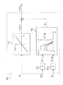
以下、本発明の一実施形態について図を参照して説明する。まず、本実施形態に係る電気式動力舵取装置の構成を図1(A),(B)に基づいて説明する。図1(A)は、本実施形態に係る電気式動力舵取装置20の全体構成例を示す構成図であり、図1(B)は、ECU40等の構成例を示す回路ブロック図である。
Hereinafter, an embodiment of the present invention will be described with reference to the drawings. First, the configuration of the electric power steering apparatus according to the present embodiment will be described based on FIGS. 1 (A) and 1 (B). FIG. 1A is a configuration diagram showing an overall configuration example of the electric
図1(A)に示すように、電気式動力舵取装置20は、主に、ステアリングホイール21、ステアリング軸22、ピニオン入力軸23、トルクセンサ24、減速機27、ラックアンドピニオン28、ロッド29、アシストモータ30、回転角センサ31およびECU40等から構成されている。
As shown in FIG. 1A, the electric
ステアリングホイール21には、ステアリング軸22の一端側が接続されており、このステアリング軸22の他端側にはトルクセンサ24の入力側が接続されている。またこのトルクセンサ24の出力側には、ラックアンドピニオン28のピニオン入力軸23の一端側が接続されている。トルクセンサ24は、図略のトーションバーとこのトーションバーを挟むようにトーションバーの両端に取り付けられた2つのレゾルバとからなり、トーションバーの一端側を入力、他端側を出力とする入出力間で生じるトーションバーの捻れ量等を当該2つのレゾルバにより検出することで、ステアリングホイール21による操舵トルクTを検出し得るように構成されている。
One end side of a
トルクセンサ24の出力側に接続されるピニオン入力軸23の途中には、減速機27が連結されており、アシストモータ30から出力されるアシスト力をこの減速機27を介してピニオン入力軸23に伝達し得るように構成されている。
A
即ち、図面には示されていないが、動力伝達機構としての減速機27は、アシストモータ30のモータ軸に取り付けられたモータギヤと減速機27の減速ギヤとが互いに噛合可能に構成されており、アシストモータ30のモータ軸が回転すると所定の減速比で減速機27の減速ギヤが回転することで、アシストモータ30による駆動力(アシスト力)をピニオン入力軸23に伝達可能にしている。なお、ピニオン入力軸23は、特許請求の範囲に記載の「操舵系」の一例に相当する。
That is, although not shown in the drawing, the speed reducer 27 as a power transmission mechanism is configured such that the motor gear attached to the motor shaft of the
アシストモータ30のモータ軸の操舵系側(アシストモータ30のロータに対して負荷方向に離間する側)には、当該モータ軸の回転角をモータ回転角θmとして検出する回転角センサ31が設けられている。本実施形態では、回転角センサ31がモータ軸の操舵系側に配置されるECU40に設けられるため、回転角センサ31がアシストモータ30のロータから離間している。なお、図1(A)では、説明の便宜上、回転角センサ31とECU40とを異なる位置にて示している。
A
このように、回転角センサ31がアシストモータ30のロータから離間すると、モータ軸の捩れにより、アシストモータ30のロータの回転角に対する回転角センサ31により検出されるモータ回転角θmの検出誤差が大きくなり、特に、小径のモータ軸を採用する場合には、モータ軸の捩れが大きくなり、上述した検出誤差がより大きくなってしまう。
Thus, when the
そこで、本実施形態では、後述するモータ回転角補正部70により、モータ回転角θmを補正するための回転角補正量Δθmを設定し、上述した検出誤差を低減するように構成されている。
Therefore, in the present embodiment, a rotation angle correction amount Δθm for correcting the motor rotation angle θm is set by a motor rotation
ピニオン入力軸23の他端側には、ラックアンドピニオン28を構成する図略のラック軸のラック溝に噛合可能なピニオンギヤが形成されている。このラックアンドピニオン28では、ピニオン入力軸23の回転運動をラック軸の直線運動に変換可能にしており、またこのラック軸の両端にはロッド29が連結され、さらにこのロッド29の端部には図略のナックル等を介して操舵輪FR、FLが連結されている。これにより、ピニオン入力軸23が回転すると、ラックアンドピニオン28、ロッド29等を介して操舵輪FR、FLの実舵角を変化させることができるので、ピニオン入力軸23の回転量および回転方向に従った操舵輪FR、FLの操舵を可能にしている。
On the other end side of the
次に、アシストモータ30の駆動制御を担うECU40の電気的構成を図1(B)に基づいて説明する。
図1(B)に示すように、ECU40は、主に、A/D変換器等の周辺LSIやメモリ等を備えたMPU(Micro Processor Unit)60、インターフェイスI/F42、およびMPU60から出力されるPWM信号に基づいてPWM制御によるモータ電流をアシストモータ30に供給可能なモータ駆動回路50等から構成されている。なお、図1(B)に示す符号47は、アシストモータ30に実際に流れるモータ電流値(3相実電流値Iu,Iv,Iw)を検出し得る電流センサ47であり、この電流センサ47により検出されたモータ電流値に関するセンサ情報は、モータ電流信号としてインターフェイスI/F42を介してMPU60に入力され得るように構成されている。
Next, the electrical configuration of the
As shown in FIG. 1B, the ECU 40 is mainly output from an MPU (Micro Processor Unit) 60 having a peripheral LSI such as an A / D converter, a memory, and the like, an interface I /
MPU60は、例えば、マイコン、半導体メモリ装置(ROM、RAM、EEPROM等)等から構成されており、電気式動力舵取装置20の基本的なアシストモータ制御を所定のコンピュータプログラムにより実行する機能を有するものである。即ち、MPU60は、トルクセンサ24により検出される操舵トルクTや回転角センサ31により検出されるモータ回転角θm、電流センサ47により検出されるモータ電流値等に基づいてアシストモータ30をベクトル制御する。
The
インターフェイスI/F42は、上述したトルクセンサ24、回転角センサ31あるいは電流センサ47等から入力される各種センサ信号を、A/D変換器等を介してMPU60の所定ポートに入力する機能等を有するものである。
The interface I /
モータ駆動回路50は、直流電源Battから供給される電力を制御可能な3相交流電力に変換する機能を有するもので(図2参照)、PWM回路とスイッチング回路等から構成されている。
The
これにより、ECU40では、後述するPI制御(比例積分制御)により、トルクセンサ24の操舵トルクTに対応する信号や回転角センサ31のモータ回転角θmに対応する信号あるいは電流センサ47の3相実電流値Iu,Iv,Iwに基づいて、操舵状態に適したアシストトルクをアシストモータ30に発生させ得るため、電気式動力舵取装置20では、ステアリングホイール21による運転者の操舵を補助可能にしている。
Thus, the
次に、ECU40によるアシストモータ30に対するPI制御系の演算処理を図2および図3に基づいて説明する。図2は、ECU40によるアシストモータ30の制御ブロック線図である。図3は、図2のモータ回転角補正部70の機能的構成を示す制御ブロック図である。なお、この演算処理は、ECU40のMPU60により、所定周期(例えば0.2mSec(ミリ秒))ごとに実行される、例えばタイマ割り込み処理によって行われている。
Next, calculation processing of the PI control system for the
図2に示すように、トルクセンサ24からMPU60に入力される操舵トルクTに対応する信号は、図略のフィルタ回路によりノイズ成分が除去された後、位相補償部61に入力される。位相補償部61では、トルクセンサ24の出力に対する応答性を速くするため位相を進める処理を行った後、位相補償されたトルク信号をアシスト制御部62およびモータ回転角補正部70に出力する。
As shown in FIG. 2, the signal corresponding to the steering torque T input from the
アシスト制御部62では、位相補償部61から入力された操舵トルクTに基づいて操舵力を補助するため、アシストモータ30に発生させる二次磁束に対する電流値、つまり界磁電流値(d軸電流指令値Id*)と、アシストトルクに対応する電流値、つまりトルク指令電流値(q軸電流指令値Iq*)とを設定する処理を行う。例えば、d軸電流指令値Id*は弱め界磁制御による設定が行われ、q軸電流指令値Iq*は検出トルクに基づいて所定のマップや演算式による設定が行われる。このように設定されたd軸電流指令値Id*およびq軸電流指令値Iq*は、それぞれPI制御部63、64の前段に位置する加算部に出力される。
The assist
PI制御部63、64の前段に位置する加算部では、アシスト制御部62から出力されるd軸電流指令値Id*およびq軸電流指令値Iq*と、後述する3相2相変換部68から帰還されるモータ駆動回路50のd軸実電流値Idおよびq軸実電流値Iqとの偏差を求める加算処理を行う。これにより、d軸電流指令値Id*とd軸実電流値Idとの偏差およびq軸電流指令値Iq*とq軸実電流値Iqとの偏差が、それぞれ算出されてPI制御部63、64に出力される。
In the addition unit positioned in front of the
PI制御部63、64では、比例積分制御が行われる。即ち、PI制御部63では、前段の加算部から出力されたd軸電流指令値Id*とd軸実電流値Idとの偏差、および、所定の比例感度と積分ゲインに基づいて比例積分演算を行い、目標値に達するまで積分値の訂正動作としてd軸電圧指令値Vd*を2相3相変換部65に出力する処理を行う。つまり、PI制御部63は、加算部とともにフィードバック演算処理を行う。
In the
またPI制御部64も同様に、q軸電流指令値Iq*とq軸実電流値Iqとの偏差、および、所定の比例感度と積分ゲインに基づいて比例積分演算を行い、目標値に達するまで積分値の訂正動作としてq軸電圧指令値Vq*を2相3相変換部65に出力する処理を行う。
Similarly, the
2相3相変換部65では、PI制御部63、64から入力されたd軸電圧指令値Vd*およびq軸電圧指令値Vq*を後述する回転角補正量Δθmが加算されたモータ回転角θmに基づいてdq逆変換(3相変換)して、各相の電圧指令値Vu*,Vv*,Vw*を演算する処理を行う。2相3相変換部65により逆変換された電圧指令値は、U相電圧指令値Vu*、V相電圧指令値Vv*、W相電圧指令値Vw*としてPWM変換部66に出力される。
In the two-phase / three-
PWM変換部66では、各相の電圧指令値Vu*,Vv*,Vw*を各相ごとのPWM指令値PWMu*,PWMv*,PWMw*に変換する処理を行う。
The
モータ駆動回路50では、PWM変換部66から出力される各相のPWM信号PWMu*,PWMv*,PWMw*に基づいて、U相、V相、W相ごとに図略のスイッチング回路をオンオフする。これにより、モータ駆動回路50は、直流電源Battから供給される直流電力を3相交流電力に変換してアシストモータ30に駆動電力を供給するので、トルクセンサ24や回転角センサ31等により検出された操舵状態に適したアシストトルクをアシストモータ30に発生させる。
In the
また、モータ駆動回路50から出力される出力電流は、各相ごとに電流センサ47に検出され、それぞれU相実電流値Iu、V相実電流値Iv、W相実電流値Iwとして3相2相変換部68に出力される。
The output current output from the
モータ回転角演算部67では、回転角センサ31から入力されるモータ回転角に対応する信号に基づいてモータ回転角θmを演算する処理を行う。このように演算されたモータ回転角θmは、モータ回転角補正部70に出力されて回転角補正量Δθmが設定され、この回転角補正量Δθmが加算されたモータ回転角θmが、3相2相変換部68に出力される。
The motor rotation
3相2相変換部68は、電流センサ47からそれぞれ入力された各相(3相)の実電流値Iu,Iv,Iwを、回転角補正量Δθmが加算されたモータ回転角θmに基づいてdq変換(2相変換)して、d軸実電流値Idおよびq軸実電流値Iqを演算する処理を行う。3相2相変換部68により変換されたモータ駆動回路50の出力電流値は、d軸実電流値Idおよびq軸実電流値Iqとして上述のPI制御部63、64の前段に位置する加算部にそれぞれフィードバック入力される。これにより、上述したようにPI制御部63、64によるフィードバック演算処理が可能となる。また、q軸実電流値Iqは、モータ回転角補正部70にも出力される。
The three-phase / two-
次に、図3を用いてモータ回転角補正部70による回転角補正量Δθmの設定処理を説明する。
図3に示すように、モータ回転角補正部70は、q軸実電流値Iq、モータ回転角θmおよび操舵トルクTに基づいて、モータ軸の捩れに起因するモータ回転角θmの検出誤差を低減するための回転角補正量Δθmを設定するものであり、基本補正量設定部71と微分器72,73とゲイン設定部74とから構成される。
Next, the setting process of the rotation angle correction amount Δθm by the motor rotation
As shown in FIG. 3, the motor rotation
基本補正量設定部71では、q軸実電流値Iqに基づいて基本補正量Δθ’mが設定される。この基本補正量Δθ’mは、モータ軸のばね定数等を考慮してq軸実電流値Iqの増加に応じて増加するように設定される。
In the basic correction
微分器72では、モータ回転角演算部67から入力されるモータ回転角θmを時間微分して回転角速度ωを演算し、この回転角速度ωをゲイン設定部74に出力する。また、微分器73では、位相補償部61から入力される操舵トルクTを時間微分してトルク微分値dT/dtを演算し、このトルク微分値dT/dtをゲイン設定部74に出力する。
The
ゲイン設定部74では、回転角速度ωおよびトルク微分値dT/dtに基づいて、基本補正量Δθ’mに乗算するためのゲインGを設定する。具体的には、図3に示すように、ゲインGは、モータ回転角の発振を抑制するため、回転角速度ωの増加に応じて減少させるように設定される。また、ゲインGは、操舵トルクに対する応答性を向上させるため、トルク微分値dT/dtの増加に応じて増加するように設定される。
The
そして、基本補正量設定部71にて設定された基本補正量Δθ’mにゲイン設定部74にて設定されたゲインGを乗算することにより、回転角補正量Δθmが設定される。
The rotation angle correction amount Δθm is set by multiplying the basic correction amount Δθ′m set by the basic correction
以上説明したように、本実施形態に係る電気式動力舵取装置20では、回転角センサ31は、モータ軸の操舵系側の回転角をモータ回転角θmとして検出し、MPU60は、q軸実電流値Iqに基づいて基本補正量Δθ’mを設定するとともに、この基本補正量Δθ’mを、回転角速度ωの増加に応じて減少させるとともにトルク微分値dT/dtの増加に応じて増加させて、モータ回転角θmを補正するための回転角補正量Δθmを設定する。
As described above, in the electric
このように、基本補正量Δθ’mは、q軸実電流値Iq、すなわち、アシストモータ30の出力トルクに基づいて設定される。そして、この基本補正量Δθ’mを、回転角速度ωの増加に応じて減少させることにより、モータ回転角θmの発振を抑制した回転角補正量Δθmを設定することができる。また、この基本補正量Δθ’mを、トルク微分値dT/dtの増加に応じて増加させることにより、操舵トルクTに対する応答性を向上した回転角補正量Δθmを設定することができる。
したがって、回転角センサ31によりモータ軸の操舵系側の回転角をモータ回転角θmとして検出する場合でも、モータ軸の捩れに起因するモータ回転角θmの検出誤差を低減することができる。
As described above, the basic correction amount Δθ′m is set based on the q-axis actual current value Iq, that is, the output torque of the
Therefore, even when the
20…電気式動力舵取装置
23…ピニオン入力軸(操舵系)
24…トルクセンサ(トルク検出手段)
30…アシストモータ(モータ)
31…回転角センサ(回転角検出手段)
40…ECU
47…電流センサ(電流値検出手段)
60…MPU(補正量設定手段,制御手段)
Iq…q軸実電流値(モータ電流値)
G…ゲイン
T…操舵トルク
θm…操舵トルク
Δθm…回転角補正量
Δθ’m…基本補正量
ω…回転角速度
dT/dt…トルク微分値
20 ... Electric
24 ... Torque sensor (torque detection means)
30 ... Assist motor (motor)
31 ... Rotation angle sensor (rotation angle detection means)
40 ... ECU
47 ... Current sensor (current value detection means)
60 ... MPU (correction amount setting means, control means)
Iq: q-axis actual current value (motor current value)
G: Gain T: Steering torque θm: Steering torque Δθm: Rotational angle correction amount Δθ'm: Basic correction amount ω: Rotational angular velocity dT / dt: Torque differential value
Claims (6)
前記操舵トルクを検出するトルク検出手段と、
前記モータにおけるモータ軸のモータ回転角を検出する回転角検出手段と、
前記モータに供給されるモータ電流値を検出する電流値検出手段と、
前記モータ回転角を補正するための回転角補正量を設定する補正量設定手段と、
前記操舵トルクと前記回転角補正量および前記モータ回転角とに基づいて前記モータを駆動制御する制御手段と、
を備える電気式動力舵取装置であって、
前記回転角検出手段は、前記モータ軸の操舵系側に配置され前記モータ軸の操舵系側の回転角を前記モータ回転角として検出し、
前記補正量設定手段は、前記モータ軸のばね定数を考慮して前記モータ電流値の増加に応じて増加するように基本補正量を設定することを特徴とする電気式動力舵取装置。 A motor capable of transmitting an assist force corresponding to the steering torque transmitted to the steering system of the vehicle to the steering system;
Torque detecting means for detecting the steering torque;
Rotation angle detection means for detecting a motor rotation angle of a motor shaft in the motor;
Current value detection means for detecting a motor current value supplied to the motor;
Correction amount setting means for setting a rotation angle correction amount for correcting the motor rotation angle;
Control means for driving and controlling the motor based on the steering torque, the rotation angle correction amount, and the motor rotation angle;
An electric power steering apparatus comprising:
The rotation angle detection means is disposed on the steering system side of the motor shaft and detects the rotation angle of the motor shaft on the steering system side as the motor rotation angle,
The electric power steering apparatus, wherein the correction amount setting means sets a basic correction amount so as to increase in accordance with an increase in the motor current value in consideration of a spring constant of the motor shaft .
前記補正量設定手段は、前記基本補正量を、前記モータ回転角の時間微分の増加に応じて減少させて、前記回転角補正量を設定することを特徴とする電気式動力舵取装置。 In the electric power steering apparatus according to claim 1,
The electric power steering apparatus, wherein the correction amount setting means sets the rotation angle correction amount by decreasing the basic correction amount in accordance with an increase in time differentiation of the motor rotation angle.
前記補正量設定手段は、前記基本補正量を、前記操舵トルクの時間微分の増加に応じて増加させて、前記回転角補正量を設定することを特徴とする電気式動力舵取装置。 In the electric power steering apparatus according to claim 1 or 2,
The electric power steering apparatus, wherein the correction amount setting means sets the rotation angle correction amount by increasing the basic correction amount in accordance with an increase in time derivative of the steering torque.
前記操舵トルクを検出するトルク検出手段と、
前記モータにおけるモータ軸のモータ回転角を検出する回転角検出手段と、
前記モータに供給されるモータ電流値を検出する電流値検出手段と、
前記モータ回転角を補正するための回転角補正量を設定する補正量設定手段と、
前記操舵トルクと前記回転角補正量および前記モータ回転角とに基づいて前記モータを駆動制御する制御手段と、
を備える電気式動力舵取装置であって、
前記回転角検出手段は、前記モータ軸の操舵系側の回転角を前記モータ回転角として検出し、
前記補正量設定手段は、前記モータ電流値に基づき前記モータ回転角の時間微分の増加に応じて減少させるように基本補正量を設定して、前記回転角補正量を設定することを特徴とする電気式動力舵取装置。 A motor capable of transmitting an assist force corresponding to the steering torque transmitted to the steering system of the vehicle to the steering system;
Torque detecting means for detecting the steering torque;
Rotation angle detection means for detecting a motor rotation angle of a motor shaft in the motor;
Current value detection means for detecting a motor current value supplied to the motor;
Correction amount setting means for setting a rotation angle correction amount for correcting the motor rotation angle;
Control means for driving and controlling the motor based on the steering torque, the rotation angle correction amount, and the motor rotation angle;
An electric power steering apparatus comprising:
The rotation angle detection means detects a rotation angle of the motor shaft on the steering system side as the motor rotation angle,
The correction amount setting means sets the rotation angle correction amount by setting a basic correction amount so as to decrease in accordance with an increase in time derivative of the motor rotation angle based on the motor current value. Electric power steering device.
前記操舵トルクを検出するトルク検出手段と、
前記モータにおけるモータ軸のモータ回転角を検出する回転角検出手段と、
前記モータに供給されるモータ電流値を検出する電流値検出手段と、
前記モータ回転角を補正するための回転角補正量を設定する補正量設定手段と、
前記操舵トルクと前記回転角補正量および前記モータ回転角とに基づいて前記モータを駆動制御する制御手段と、
を備える電気式動力舵取装置であって、
前記回転角検出手段は、前記モータ軸の操舵系側の回転角を前記モータ回転角として検出し、
前記補正量設定手段は、前記モータ電流値に基づき前記操舵トルクの時間微分の増加に応じて増加させるように基本補正量を設定して、前記回転角補正量を設定することを特徴とする電気式動力舵取装置。 A motor capable of transmitting an assist force corresponding to the steering torque transmitted to the steering system of the vehicle to the steering system;
Torque detecting means for detecting the steering torque;
Rotation angle detection means for detecting a motor rotation angle of a motor shaft in the motor;
Current value detection means for detecting a motor current value supplied to the motor;
Correction amount setting means for setting a rotation angle correction amount for correcting the motor rotation angle;
Control means for driving and controlling the motor based on the steering torque, the rotation angle correction amount, and the motor rotation angle;
An electric power steering apparatus comprising:
The rotation angle detection means detects a rotation angle of the motor shaft on the steering system side as the motor rotation angle,
The correction amount setting means sets the rotation angle correction amount by setting a basic correction amount based on the motor current value so as to increase according to an increase in time derivative of the steering torque. Power steering device.
前記補正量設定手段は、前記基本補正量を、前記モータ回転角の時間微分の増加に応じて減少させて、前記回転角補正量を設定することを特徴とする電気式動力舵取装置。 In the electric power steering apparatus according to claim 5,
The electric power steering apparatus, wherein the correction amount setting means sets the rotation angle correction amount by decreasing the basic correction amount in accordance with an increase in time differentiation of the motor rotation angle.
Priority Applications (4)
| Application Number | Priority Date | Filing Date | Title |
|---|---|---|---|
| JP2009010916A JP5381117B2 (en) | 2009-01-21 | 2009-01-21 | Electric power steering device |
| US12/688,250 US7913805B2 (en) | 2009-01-21 | 2010-01-15 | Electric power steering apparatus |
| EP10151179.8A EP2210795B1 (en) | 2009-01-21 | 2010-01-20 | Electric power steering apparatus |
| CN2010100033632A CN101780810B (en) | 2009-01-21 | 2010-01-21 | Electric power steering apparatus |
Applications Claiming Priority (1)
| Application Number | Priority Date | Filing Date | Title |
|---|---|---|---|
| JP2009010916A JP5381117B2 (en) | 2009-01-21 | 2009-01-21 | Electric power steering device |
Publications (3)
| Publication Number | Publication Date |
|---|---|
| JP2010167854A JP2010167854A (en) | 2010-08-05 |
| JP2010167854A5 JP2010167854A5 (en) | 2012-02-09 |
| JP5381117B2 true JP5381117B2 (en) | 2014-01-08 |
Family
ID=41610744
Family Applications (1)
| Application Number | Title | Priority Date | Filing Date |
|---|---|---|---|
| JP2009010916A Expired - Fee Related JP5381117B2 (en) | 2009-01-21 | 2009-01-21 | Electric power steering device |
Country Status (4)
| Country | Link |
|---|---|
| US (1) | US7913805B2 (en) |
| EP (1) | EP2210795B1 (en) |
| JP (1) | JP5381117B2 (en) |
| CN (1) | CN101780810B (en) |
Families Citing this family (12)
| Publication number | Priority date | Publication date | Assignee | Title |
|---|---|---|---|---|
| DE102012012308B3 (en) * | 2012-06-20 | 2013-02-28 | Ssb Wind Systems Gmbh & Co. Kg | Rotational angle sensor for use in rotating shaft of wind-power plant to determine e.g. rotor speed, has measuring element with chain elements whose rollers are aligned in direction of shaft, where chain is attached on shaft circumference |
| JP2015002567A (en) | 2013-06-13 | 2015-01-05 | Ntn株式会社 | Controller of electric car |
| KR102089923B1 (en) * | 2013-11-13 | 2020-03-17 | 현대모비스 주식회사 | Control apparatus and method for position compensating of electric power steering motor |
| JP5915680B2 (en) * | 2014-03-20 | 2016-05-11 | トヨタ自動車株式会社 | Steering control device |
| JP5935960B2 (en) * | 2014-03-25 | 2016-06-15 | 日本精工株式会社 | Electric power steering device |
| JP6657757B2 (en) * | 2015-10-15 | 2020-03-04 | 株式会社ジェイテクト | Steering control device |
| US9879463B2 (en) * | 2016-02-26 | 2018-01-30 | Waymo Llc | Device and method for powered closing of car doors |
| EP3626581B1 (en) * | 2017-05-18 | 2020-12-30 | Mitsubishi Electric Corporation | Electric power steering apparatus and method for controlling electric power steering apparatus |
| WO2019092777A1 (en) * | 2017-11-07 | 2019-05-16 | 三菱電機株式会社 | Electric motor control device and electric power steering device |
| DE102018106997A1 (en) * | 2018-03-23 | 2019-09-26 | Thyssenkrupp Ag | Torque-dependent correction of the rotation angle of a steering shaft of an electromechanical motor vehicle steering |
| JP7117233B2 (en) * | 2018-12-14 | 2022-08-12 | 日本電産モビリティ株式会社 | Electronic control device, control method, and electronic control program |
| WO2020194667A1 (en) * | 2019-03-28 | 2020-10-01 | 株式会社ショーワ | Steering control device and electric power steering device |
Family Cites Families (10)
| Publication number | Priority date | Publication date | Assignee | Title |
|---|---|---|---|---|
| JPH07172324A (en) * | 1993-12-20 | 1995-07-11 | Honda Motor Co Ltd | Motor-driven power steering device |
| CA2413379C (en) * | 2001-12-06 | 2010-02-09 | Honda Giken Kogyo Kabushiki Kaisha | Electric power steering apparatus |
| JP2003200846A (en) * | 2002-01-09 | 2003-07-15 | Koyo Seiko Co Ltd | Electric power steering system |
| JP4120420B2 (en) * | 2003-02-20 | 2008-07-16 | 日産自動車株式会社 | Motor control device |
| JP4385276B2 (en) * | 2003-05-08 | 2009-12-16 | 株式会社ジェイテクト | Motor control device |
| JP4202872B2 (en) * | 2003-09-12 | 2008-12-24 | 株式会社ジェイテクト | Vehicle steering system |
| JP4779495B2 (en) | 2004-10-27 | 2011-09-28 | 日産自動車株式会社 | Vehicle steering system |
| JP4228237B2 (en) * | 2006-06-06 | 2009-02-25 | トヨタ自動車株式会社 | Electric power steering device |
| JP4518133B2 (en) | 2007-10-24 | 2010-08-04 | 株式会社デンソー | Electric power steering control device |
| EP2080687B1 (en) * | 2008-01-16 | 2011-12-14 | Jtekt Corporation | Electric power steering device |
-
2009
- 2009-01-21 JP JP2009010916A patent/JP5381117B2/en not_active Expired - Fee Related
-
2010
- 2010-01-15 US US12/688,250 patent/US7913805B2/en not_active Expired - Fee Related
- 2010-01-20 EP EP10151179.8A patent/EP2210795B1/en not_active Not-in-force
- 2010-01-21 CN CN2010100033632A patent/CN101780810B/en not_active Expired - Fee Related
Also Published As
| Publication number | Publication date |
|---|---|
| EP2210795A1 (en) | 2010-07-28 |
| CN101780810B (en) | 2013-03-20 |
| EP2210795B1 (en) | 2014-04-09 |
| CN101780810A (en) | 2010-07-21 |
| JP2010167854A (en) | 2010-08-05 |
| US20100181140A1 (en) | 2010-07-22 |
| US7913805B2 (en) | 2011-03-29 |
Similar Documents
| Publication | Publication Date | Title |
|---|---|---|
| JP5381117B2 (en) | Electric power steering device | |
| JP5082719B2 (en) | Motor control device and electric power steering device | |
| EP2398142B1 (en) | Motor control device and electric power steering device | |
| US8504242B2 (en) | Motor controller and electronic power steering apparatus | |
| EP1967443A2 (en) | Electric power steering apparatus, controlling method thereof and program for electric power steering apparatus | |
| JP2009269540A (en) | Electric power steering device | |
| JP2009046005A (en) | Electric power steering device | |
| JP2006131179A (en) | Electric power steering device | |
| JP2020069864A (en) | Steering control device | |
| JP2008006919A (en) | Electric power steering device | |
| JP2014139039A (en) | Electric power steering device | |
| JP5012157B2 (en) | Electric power steering device | |
| JP2013005624A (en) | Vehicle steering device | |
| JP5056176B2 (en) | Motor control device and electric power steering device | |
| JP2008155683A (en) | Electric power steering device | |
| JP4333441B2 (en) | Power steering device | |
| JP5176369B2 (en) | Electric power steering device | |
| JP2008183987A (en) | Electric power steering device | |
| JP2012240440A (en) | Electric power steering device | |
| JP2013189123A (en) | Electric power steering device | |
| JP2013126822A (en) | Electric power steering apparatus | |
| JP5217901B2 (en) | Electric power steering device | |
| JP2012166769A (en) | Electric power steering device | |
| JP2007118785A (en) | Steering assisting device of vehicle | |
| JP2008254522A (en) | Steering device |
Legal Events
| Date | Code | Title | Description |
|---|---|---|---|
| A521 | Written amendment |
Free format text: JAPANESE INTERMEDIATE CODE: A523 Effective date: 20111215 |
|
| A621 | Written request for application examination |
Free format text: JAPANESE INTERMEDIATE CODE: A621 Effective date: 20111215 |
|
| A977 | Report on retrieval |
Free format text: JAPANESE INTERMEDIATE CODE: A971007 Effective date: 20130325 |
|
| A131 | Notification of reasons for refusal |
Free format text: JAPANESE INTERMEDIATE CODE: A131 Effective date: 20130402 |
|
| A521 | Written amendment |
Free format text: JAPANESE INTERMEDIATE CODE: A523 Effective date: 20130520 |
|
| A02 | Decision of refusal |
Free format text: JAPANESE INTERMEDIATE CODE: A02 Effective date: 20130607 |
|
| A521 | Written amendment |
Free format text: JAPANESE INTERMEDIATE CODE: A523 Effective date: 20130718 |
|
| A911 | Transfer to examiner for re-examination before appeal (zenchi) |
Free format text: JAPANESE INTERMEDIATE CODE: A911 Effective date: 20130815 |
|
| TRDD | Decision of grant or rejection written | ||
| A01 | Written decision to grant a patent or to grant a registration (utility model) |
Free format text: JAPANESE INTERMEDIATE CODE: A01 Effective date: 20130903 |
|
| A61 | First payment of annual fees (during grant procedure) |
Free format text: JAPANESE INTERMEDIATE CODE: A61 Effective date: 20130916 |
|
| R150 | Certificate of patent or registration of utility model |
Ref document number: 5381117 Country of ref document: JP Free format text: JAPANESE INTERMEDIATE CODE: R150 Free format text: JAPANESE INTERMEDIATE CODE: R150 |
|
| LAPS | Cancellation because of no payment of annual fees |