EP3009768A1 - Machine for air-cooled absorption - Google Patents
Machine for air-cooled absorption Download PDFInfo
- Publication number
- EP3009768A1 EP3009768A1 EP14810571.1A EP14810571A EP3009768A1 EP 3009768 A1 EP3009768 A1 EP 3009768A1 EP 14810571 A EP14810571 A EP 14810571A EP 3009768 A1 EP3009768 A1 EP 3009768A1
- Authority
- EP
- European Patent Office
- Prior art keywords
- air
- machine according
- cooled absorption
- absorption machine
- cooled
- Prior art date
- Legal status (The legal status is an assumption and is not a legal conclusion. Google has not performed a legal analysis and makes no representation as to the accuracy of the status listed.)
- Granted
Links
Images


Classifications
-
- F—MECHANICAL ENGINEERING; LIGHTING; HEATING; WEAPONS; BLASTING
- F25—REFRIGERATION OR COOLING; COMBINED HEATING AND REFRIGERATION SYSTEMS; HEAT PUMP SYSTEMS; MANUFACTURE OR STORAGE OF ICE; LIQUEFACTION SOLIDIFICATION OF GASES
- F25B—REFRIGERATION MACHINES, PLANTS OR SYSTEMS; COMBINED HEATING AND REFRIGERATION SYSTEMS; HEAT PUMP SYSTEMS
- F25B15/00—Sorption machines, plants or systems, operating continuously, e.g. absorption type
- F25B15/02—Sorption machines, plants or systems, operating continuously, e.g. absorption type without inert gas
- F25B15/06—Sorption machines, plants or systems, operating continuously, e.g. absorption type without inert gas the refrigerant being water vapour evaporated from a salt solution, e.g. lithium bromide
-
- F—MECHANICAL ENGINEERING; LIGHTING; HEATING; WEAPONS; BLASTING
- F25—REFRIGERATION OR COOLING; COMBINED HEATING AND REFRIGERATION SYSTEMS; HEAT PUMP SYSTEMS; MANUFACTURE OR STORAGE OF ICE; LIQUEFACTION SOLIDIFICATION OF GASES
- F25B—REFRIGERATION MACHINES, PLANTS OR SYSTEMS; COMBINED HEATING AND REFRIGERATION SYSTEMS; HEAT PUMP SYSTEMS
- F25B37/00—Absorbers; Adsorbers
-
- F—MECHANICAL ENGINEERING; LIGHTING; HEATING; WEAPONS; BLASTING
- F25—REFRIGERATION OR COOLING; COMBINED HEATING AND REFRIGERATION SYSTEMS; HEAT PUMP SYSTEMS; MANUFACTURE OR STORAGE OF ICE; LIQUEFACTION SOLIDIFICATION OF GASES
- F25B—REFRIGERATION MACHINES, PLANTS OR SYSTEMS; COMBINED HEATING AND REFRIGERATION SYSTEMS; HEAT PUMP SYSTEMS
- F25B39/00—Evaporators; Condensers
- F25B39/02—Evaporators
- F25B39/026—Evaporators specially adapted for sorption type systems
-
- Y—GENERAL TAGGING OF NEW TECHNOLOGICAL DEVELOPMENTS; GENERAL TAGGING OF CROSS-SECTIONAL TECHNOLOGIES SPANNING OVER SEVERAL SECTIONS OF THE IPC; TECHNICAL SUBJECTS COVERED BY FORMER USPC CROSS-REFERENCE ART COLLECTIONS [XRACs] AND DIGESTS
- Y02—TECHNOLOGIES OR APPLICATIONS FOR MITIGATION OR ADAPTATION AGAINST CLIMATE CHANGE
- Y02A—TECHNOLOGIES FOR ADAPTATION TO CLIMATE CHANGE
- Y02A30/00—Adapting or protecting infrastructure or their operation
- Y02A30/27—Relating to heating, ventilation or air conditioning [HVAC] technologies
-
- Y—GENERAL TAGGING OF NEW TECHNOLOGICAL DEVELOPMENTS; GENERAL TAGGING OF CROSS-SECTIONAL TECHNOLOGIES SPANNING OVER SEVERAL SECTIONS OF THE IPC; TECHNICAL SUBJECTS COVERED BY FORMER USPC CROSS-REFERENCE ART COLLECTIONS [XRACs] AND DIGESTS
- Y02—TECHNOLOGIES OR APPLICATIONS FOR MITIGATION OR ADAPTATION AGAINST CLIMATE CHANGE
- Y02B—CLIMATE CHANGE MITIGATION TECHNOLOGIES RELATED TO BUILDINGS, e.g. HOUSING, HOUSE APPLIANCES OR RELATED END-USER APPLICATIONS
- Y02B30/00—Energy efficient heating, ventilation or air conditioning [HVAC]
- Y02B30/62—Absorption based systems
Definitions
- the present invention relates to the design of an air-cooled absorption refrigerating machine that uses water as coolant and aqueous lithium bromide to be used in air-conditioning applications and whose energy source is hot water.
- Absorption refrigeration is one of the several existent technologies to create cold from a thermal energy source, and it is one of the most widespread.
- Absorption refrigerating machines have been around since the 19 th century and throughout the 20 th century several makers of medium/large capacity (above 100 kW) machines have made their niche in the market. All these machines use either water (coolant)/aqueous lithium bromide (absorber), or ammonium (coolant)/ammonia liquor (absorber) as working fluids.
- the machines that use water as coolant are adequate for air-conditioning applications, and the machines that use ammonium as coolant for refrigeration applications.
- thermochemical energy there is a water/aqueous lithium chloride machine working in open cycle that has as one further characteristic the ability to store thermochemical energy.
- WO2009102271 "Absorption machine having a built-in energy storage tank working according to the matrix method.”
- Patents JP63065257 Air-cooling type absorption water chiller and heater
- JP2251067 Absorption type air-cooled heat pump cooling and heating device
- JP3091664 Air-cooled absorption type heating and cooling equipment
- JP3105177 Air-cooled absorption type water cooling and heating machine
- JP10281581 Air-cooling absorption freezer and cold/warm water heater
- EP0317048 Air-cooled absorption type water cooling and heating generating apparatus
- EP0216629 Air-cooled absorption type water cooling/heating apparatus
- US4563882 Air-cooling type absorption cooler
- US4655053 Air-cooled absorption refrigeration system
- US4691528 Air-cooled absorption type water cooling/heating apparatus
- US4748830 Air-cooled absorption absorption
- absorption refrigerating machines are made up by an array of heat exchangers, pumps and valves.
- a rather usual type of heat exchanger is of the film descending type, since this does not involve a large pressure loss on the side of the primary fluid or coolant (water/aqueous lithium bromide). This is an important characteristic, since these machines work at subatmospheric pressures.
- Patents JP3091664 , JP3105177 , JP63065257 , JP9014787 , JP10030860 , JP10281581 , JP10300268 , US4655053 reference is made to vertical film absorbers.
- Another type of exchanger appropriate for machines that use water/aqueous lithium bromide is the flooded variety, which can be used in evaporators and/or generators.
- the solution exchanger which is a liquid-liquid exchanger, which can be a plate or a shell and tube exchanger.
- the purpose of the present invention is to improve the design of an absorption refrigerating machine directly cooled by air that works with hot water as the energy source, with a single effect configuration.
- the absorption refrigerating machine that is the subject of the current invention presents a single effect cycle configuration.
- the basic single effect absorption cycle consists of one absorber, one generator, one solution exchanger, one evaporator, one condenser, one pump and two expansion valves (see Figure 1 ).
- the absorption refrigerating machine whose invention is herein referred to is characterised by having a parallelepiped shape (see Figure 2 ) inside of which all components are located. Said components are arranged so that they leave its central part hollow, so that air circulation is permitted in its interior.
- a fan In the upper part of the machine a fan is located that moves the air in forced convection through the finned tube exchangers, these being located on two of the lateral sides of the parallelepiped, so that air is drawn inside through the finned exchangers, circulates upwards through the central hollow part and exits through the fan by the top of the machine.
- These finned exchangers are the absorber and the condenser, which, in turn, may be divided into two parts, and located on just two sides, setting up what is termed parallel installation.
- the fan is located on the upper side of the parallelepiped, just above the generator, and the latter, in turn, above the solution exchanger and the absorbers.
- the solution exchanger will be at such a height that its top will be level with the upper part of the absorbers. All the elements are arranged in the shape of a hollow box, the interior allowing for the possibility of free circulation of the air in forced convection being drawn inside by the condensers and the absorbers, exiting through the fan by the top of the machine.
- the solution and coolant storage tanks are located at the bottom of the parallelepiped without hindering the passage of air.
- the generator is located in the upper part of the machine, under the fan and above the absorber or absorbers and the solution exchanger, to facilitate the return flow from the generator to the absorber.
- the absorber is located under the generator, high enough relative to the pump.
- the solution exchanger is located under the generator and in the upper part of the absorber, in order to facilitate the return flow from the generator to the absorber.
- the evaporator is located at the bottom.
- the absorber is a finned tube exchanger (see Figure 3 ). Inside it the primary fluid -the aqueous solution of lithium bromide- circulates absorbing water vapour in the shape of a vertically descending liquid film. In this process, the heat and mass transfer is effected simultaneously, as described in the reference: Grossman, G. "Simultaneous heat and mass transfer in film absorption under laminar flow.” On the outside of the tubes the air cooling the exchanger circulates. In order to ensure an adequate liquid film flow, a descending film former is installed in the upper part of the tubes. Two options are presented: i) a cylinder with a threaded hole and slots which engages the tube; ii) a film former based on passing the solution through a very narrow annular conduit (see Figure 4 ).
- the condenser is a finned tubed exchanger. Inside it the primary fluid -condensed water- circulates. On the outside of the tubes the air cooling the exchanger circulates (see Figure 5 ).
- the generator is a coil exchanger of horizontal tubes, where the primary fluid (an aqueous solution of lithium bromide) circulates on the outside of the tubes and the secondary fluid (hot water) circulates inside them.
- Wire netting is installed to facilitate the wetting on the horizontal coil.
- Two threaded rods are located between one tube and the next so as to ensure a good distribution of the liquid in the shape of a descending film on the generator coil.
- the generator tubes subtend an angle relative to the horizontal smaller than 0.5°, so that they do not constitute a helical coil by virtue of oblique links that make up one of the corners.
- the liquid distributor consists of a tube with gaged holes that equitably shares out the aqueous solution of lithium bromide on the first tube (see Figure 6 ).
- the evaporator is of the flooded type. This type of evaporators avoids the need for coolant pumps. It consists of a bundle of finned tubes (see Figure 6 ).
- the passage between the evaporator and the absorber, and between the generator and the condenser is sufficient to minimise pressure losses and to achieve the proper operation of the machine.
- the solution and coolant tanks have enough capacity to let them operate in the right working concentration range and enough capacity to thermochemically store energy.
- the solution tank is divided in two, and is located above the pump to ensure the latter's priming.
- the coolant tank is unique, and is also located above the pump. It is used both to adjust the concentration level and to anticipate the decrystallisation process.
- the preferred embodiment of the present invention is laid out with a parallelepiped shape inside of which the different components (see Figure 2 ) are located: generator (1), condensers (2), evaporators (3), absorbers (4), solution exchanger (5), solution storage tank (6), coolant storage tank (7), expansion valves (8), pump (9), liquid conduits (10), vapour conduits (11), fan (12). While the basic absorption cycle consists of one generator (1), one condenser (2), one evaporator (3), one absorber (4), one solution exchanger (5), two expansion valves (8) and one solution pump (9) that can be mechanical or thermal (see Figure 1 ), in the preferred embodiment the condenser (2), the evaporator (3) and the absorber (4) are divided into two equal parts.
- the air-cooled exchangers that is, the absorbers (4) and the condensers (5), are located on opposite vertical sides of the parallelepiped, whose lengths will be the larger thereof.
- the absorbers (4) will be located above the condensers.
- the solution pump (9) will be located at the bottom of the parallelepiped, in the middle of the two evaporators (3).
- Another preferred embodiment is the arrangement of the array of condensers (2) and absorbers (4) in series (see Figure 8 ), twice of each in this case.
- the rest of the main components -generator (1), evaporator (3), solution exchanger (5), solution storage tank (6), coolant storage tank (7), expansion valves (8), pump (9), fan (12)- would stay the same as the above preferred form, except for the liquid (10) and vapour (11) conduits, which are adapted to the new arrangement of the air-cooled components:
- the main advantage of this arrangement is that it occupies a smaller frontal area.
- an arrangement of the array of condensers (2) and absorbers (4) in parallel is laid out, but with the condensers (2) subtending some angle to the vertical (see Figure 9 ).
- the rest of the main components -generator (1), evaporator (3), solution exchanger (5), solution storage tank (6), coolant storage tank (7), expansion valves (8), pump (9), fan (12)- would stay the same as the above preferred form, except for the liquid (10) and vapour (11) conduits, which are adapted to the new arrangement of the air-cooled components.
- the main advantage of this arrangement is that it facilitates the suction of the air flow, reducing pressure losses on the fan, combining the advantage of the first preferred embodiment, that is, maximising the frontal area.
- One alternative as a preferred embodiment is the arrangement of the array of condensers (2) and absorbers (4) in series, but with the absorbers (4) and condensers (2) subtending some angle to the vertical (see Figure 10 ).
- the rest of the main components -generator (1), evaporator (3), solution exchanger (5), solution storage tank (6), coolant storage tank (7), expansion valves (8), solution pump (9), fan (12)- would stay the same as the above preferred form, except for the liquid (10) and vapour (11) conduits, which are adapted to the new arrangement of the air-cooled components.
- the main advantage of this arrangement is that it facilitates the suction of the air flow, combining the advantage of the second preferred embodiment, that is, occupying a smaller frontal area.
Landscapes
- Engineering & Computer Science (AREA)
- Chemical & Material Sciences (AREA)
- Materials Engineering (AREA)
- Physics & Mathematics (AREA)
- Mechanical Engineering (AREA)
- Thermal Sciences (AREA)
- General Engineering & Computer Science (AREA)
- Sorption Type Refrigeration Machines (AREA)
- Heat-Exchange Devices With Radiators And Conduit Assemblies (AREA)
- Greenhouses (AREA)
Abstract
Description
- The present invention relates to the design of an air-cooled absorption refrigerating machine that uses water as coolant and aqueous lithium bromide to be used in air-conditioning applications and whose energy source is hot water.
- There are currently a lot of technologies to create cold from a thermal energy source; for instance, refrigeration through absorption, adsorption, ejection, cold through desiccants, the Rankine cycle, the Stirling cycle, etc. These technologies are particularly attractive to diminish the demand for electrical energy and to replace the traditional systems of vapour compression. This may mean remarkable savings from the energy and, consequently, economic perspectives, provided the thermal energy source has a low price; for instance, solar energy or residual heat from an industrial process.
- Absorption refrigeration is one of the several existent technologies to create cold from a thermal energy source, and it is one of the most widespread. Absorption refrigerating machines have been around since the 19th century and throughout the 20th century several makers of medium/large capacity (above 100 kW) machines have made their niche in the market. All these machines use either water (coolant)/aqueous lithium bromide (absorber), or ammonium (coolant)/ammonia liquor (absorber) as working fluids. The machines that use water as coolant are adequate for air-conditioning applications, and the machines that use ammonium as coolant for refrigeration applications.
- During that time, the Yazaki company has been a unique case. See, for instance, Patent
US4014183 , "Absorption refrigerator of natural circulation type," with its low power models in the range of 7-50 kW. All these machines use water and lithium bromide as working fluids. - In the first decade of the 21st century there was a strong development of low-power absorption machines, particularly those of water/aqueous lithium bromide. See Patents
DE102007062343 "Cold production method for water lithium bromide absorption refrigerant plant, involves receiving water vapor by mixing absorber, and supplying lithium bromide solution into cooling part via desorber" andWO2009004008 "Absorption refrigerating machine." - There is a water/aqueous lithium chloride machine working in open cycle that has as one further characteristic the ability to store thermochemical energy. As one illustrative patent, see reference
WO2009102271 , "Absorption machine having a built-in energy storage tank working according to the matrix method." - All the commercial machines described above are cooled by water and they use water as the coolant and aqueous lithium bromide as the absorber, and they need a cooling tower for their operation.
- For low power machines dispensing with the cooling tower is attractive, since that would make the system cheaper. Up to now, some developments of air-cooled absorption machines have been made that use water/aqueous lithium bromide, none of which have become commercially viable. We shall mention Patents
JP63065257 JP2251067 JP3091664 JP3105177 JP10281581 EP0317048 "Air-cooled absorption type water cooling and heating generating apparatus,"EP0216629 "Air-cooled absorption type water cooling/heating apparatus,"US4563882 "Air-cooling type absorption cooler,"US4655053 "Air-cooled absorption refrigeration system,US4691528 "Air-cooled absorption type water cooling/heating apparatus,"US4748830 "Air-cooled absorption heating and cooling system,"US4748830 "Air-cooled absorption heating and cooling system,"US4791790 "Air-cooled absorption-type water cooling and heating apparatus,"US4872319 "Air-cooled absorption type cooling/heating water generating apparatus,"US4841744 "Double-effect air-cooled absorption refrigerating machine,"US5027616 "Air-cooled absorption type cooling and heating apparatus" andES2159250B1 ES2159250B1 US6109060 , titled "Air-cooled absorption type refrigerating apparatus," relates to an air-cooled absorption machine with different configurations of its elements. - As for components, absorption refrigerating machines are made up by an array of heat exchangers, pumps and valves. In the case of machines using water/aqueous lithium bromide, a rather usual type of heat exchanger is of the film descending type, since this does not involve a large pressure loss on the side of the primary fluid or coolant (water/aqueous lithium bromide). This is an important characteristic, since these machines work at subatmospheric pressures. In Patents
JP3091664 JP3105177 JP63065257 JP9014787 JP10030860 JP10281581 JP10300268 US4655053 reference is made to vertical film absorbers. There is another absorber configuration, known as adiabatic absorption in droplets, which appears in PatentES2161119 JP10300273 JP10300274 - Another type of exchanger appropriate for machines that use water/aqueous lithium bromide is the flooded variety, which can be used in evaporators and/or generators. There is one further component, the solution exchanger, which is a liquid-liquid exchanger, which can be a plate or a shell and tube exchanger.
- The purpose of the present invention is to improve the design of an absorption refrigerating machine directly cooled by air that works with hot water as the energy source, with a single effect configuration.
- It specifically relates to the spatial arrangement of its components -absorber, generator, solution exchanger, condenser, evaporator, solution pump, solution and coolant storage tanks-, to some design details of the heat exchangers and to the design of its distributors, which is essential to achieve a good wetting of the descending film heat exchangers that require it: the absorber and the generator.
- The absorption refrigerating machine that is the subject of the current invention presents a single effect cycle configuration. The basic single effect absorption cycle consists of one absorber, one generator, one solution exchanger, one evaporator, one condenser, one pump and two expansion valves (see
Figure 1 ). - The absorption refrigerating machine whose invention is herein referred to is characterised by having a parallelepiped shape (see
Figure 2 ) inside of which all components are located. Said components are arranged so that they leave its central part hollow, so that air circulation is permitted in its interior. In the upper part of the machine a fan is located that moves the air in forced convection through the finned tube exchangers, these being located on two of the lateral sides of the parallelepiped, so that air is drawn inside through the finned exchangers, circulates upwards through the central hollow part and exits through the fan by the top of the machine. These finned exchangers are the absorber and the condenser, which, in turn, may be divided into two parts, and located on just two sides, setting up what is termed parallel installation. The fan is located on the upper side of the parallelepiped, just above the generator, and the latter, in turn, above the solution exchanger and the absorbers. The solution exchanger will be at such a height that its top will be level with the upper part of the absorbers. All the elements are arranged in the shape of a hollow box, the interior allowing for the possibility of free circulation of the air in forced convection being drawn inside by the condensers and the absorbers, exiting through the fan by the top of the machine. The solution and coolant storage tanks are located at the bottom of the parallelepiped without hindering the passage of air. - The generator is located in the upper part of the machine, under the fan and above the absorber or absorbers and the solution exchanger, to facilitate the return flow from the generator to the absorber.
- The absorber is located under the generator, high enough relative to the pump.
- The solution exchanger is located under the generator and in the upper part of the absorber, in order to facilitate the return flow from the generator to the absorber.
- The evaporator is located at the bottom.
- The absorber is a finned tube exchanger (see
Figure 3 ). Inside it the primary fluid -the aqueous solution of lithium bromide- circulates absorbing water vapour in the shape of a vertically descending liquid film. In this process, the heat and mass transfer is effected simultaneously, as described in the reference: Grossman, G. "Simultaneous heat and mass transfer in film absorption under laminar flow." On the outside of the tubes the air cooling the exchanger circulates. In order to ensure an adequate liquid film flow, a descending film former is installed in the upper part of the tubes. Two options are presented: i) a cylinder with a threaded hole and slots which engages the tube; ii) a film former based on passing the solution through a very narrow annular conduit (seeFigure 4 ). - The condenser is a finned tubed exchanger. Inside it the primary fluid -condensed water- circulates. On the outside of the tubes the air cooling the exchanger circulates (see
Figure 5 ). - The generator is a coil exchanger of horizontal tubes, where the primary fluid (an aqueous solution of lithium bromide) circulates on the outside of the tubes and the secondary fluid (hot water) circulates inside them. Wire netting is installed to facilitate the wetting on the horizontal coil. Two threaded rods are located between one tube and the next so as to ensure a good distribution of the liquid in the shape of a descending film on the generator coil. The generator tubes subtend an angle relative to the horizontal smaller than 0.5°, so that they do not constitute a helical coil by virtue of oblique links that make up one of the corners. The liquid distributor consists of a tube with gaged holes that equitably shares out the aqueous solution of lithium bromide on the first tube (see
Figure 6 ). - The evaporator is of the flooded type. This type of evaporators avoids the need for coolant pumps. It consists of a bundle of finned tubes (see
Figure 6 ). - The passage between the evaporator and the absorber, and between the generator and the condenser is sufficient to minimise pressure losses and to achieve the proper operation of the machine.
- Under no circumstances the binding of members of different metals to be brought together is to be done through welding, but effected through polymeric, elastomeric or rigid joints.
- The solution and coolant tanks have enough capacity to let them operate in the right working concentration range and enough capacity to thermochemically store energy. The solution tank is divided in two, and is located above the pump to ensure the latter's priming. The coolant tank, however, is unique, and is also located above the pump. It is used both to adjust the concentration level and to anticipate the decrystallisation process.
- Other details and characteristics will be shown in the following description, wherein different examples of the invention are shown by way of non-limiting examples, along with the relevant Figures.
- Herein below is a list of the different parts of the invention that are identified in the attached Figures with the help of numbers: (1) generator, (2) condenser, (3) evaporator, (4) absorber, (5) solution exchanger, (6) solution storage tank, (7) coolant storage tank, (8) expansion valves, (9) pump, (10) liquid conduits, (11) vapour conduits, (12) fan, (13) liquid distributor, (14) liquid film former, (15) redistributing rod, (16) wire netting covering, (17) finned tube.
-
-
Figure 1 portrays the basic absorption cycle. -
Figure 2 is a basic diagram of the views of the first preferred embodiment of the machine wherein the absorbers (5) and the condensers (2) can be seen in parallel. -
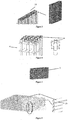
Figure 3 shows schematic representations of the air-cooled absorber (4), where in the view on the left the top of the absorber (4) is shown as having the liquid film formers (14), and in the view on the right the entire absorber (4) can be seen. -
Figure 4 shows schematic representations of the annular liquid film formers (14), where in the view on the left a detail thereof (14) located in the upper part of the absorber (4) can be seen, and in the view on the right a film former (14) can be seen by itself. -
Figure 5 is a schematic representation of the air-cooled condenser (2). -
Figure 6 is a schematic representation of the coil generator (1) with the distributor (13) on top. The structural detail of the coil corner can be seen highlighted. On the right there is a section of the tubes of the generator (1), with the redistributing rods (15) located therebetween. -
Figure 7 is a schematic representation of the flooded evaporator (3), which consists of a bundle of finned tubes. -
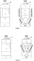
Figure 8 is a basic scheme of the views of the second preferred embodiment of the machine wherein the absorbers (5) and the condensers (2) can be seen in series. -
Figure 9 is a basic scheme of the views of the third preferred embodiment of the machine wherein the absorbers (5) and the condensers (2) can be seen in parallel, the latter being formed at an angle to the vertical. -
Figure 10 is a basic scheme of the views of the fourth preferred embodiment of the machine wherein the absorbers (5) and the condensers (2) can be seen in series, the latter being formed at an angle to the vertical. - The preferred embodiment of the present invention is laid out with a parallelepiped shape inside of which the different components (see
Figure 2 ) are located: generator (1), condensers (2), evaporators (3), absorbers (4), solution exchanger (5), solution storage tank (6), coolant storage tank (7), expansion valves (8), pump (9), liquid conduits (10), vapour conduits (11), fan (12). While the basic absorption cycle consists of one generator (1), one condenser (2), one evaporator (3), one absorber (4), one solution exchanger (5), two expansion valves (8) and one solution pump (9) that can be mechanical or thermal (seeFigure 1 ), in the preferred embodiment the condenser (2), the evaporator (3) and the absorber (4) are divided into two equal parts. The air-cooled exchangers, that is, the absorbers (4) and the condensers (5), are located on opposite vertical sides of the parallelepiped, whose lengths will be the larger thereof. The absorbers (4) will be located above the condensers. The solution pump (9) will be located at the bottom of the parallelepiped, in the middle of the two evaporators (3). The advantage of this preferred embodiment is that it ensures the intake of fresh air both in the condensers and the absorbers, thanks to their parallel arrangement, with a maximum of frontal area, with minimal pressure loss in the air flow. - Another preferred embodiment is the arrangement of the array of condensers (2) and absorbers (4) in series (see
Figure 8 ), twice of each in this case. The rest of the main components -generator (1), evaporator (3), solution exchanger (5), solution storage tank (6), coolant storage tank (7), expansion valves (8), pump (9), fan (12)- would stay the same as the above preferred form, except for the liquid (10) and vapour (11) conduits, which are adapted to the new arrangement of the air-cooled components: The main advantage of this arrangement is that it occupies a smaller frontal area. - As an alternative preferred embodiment, an arrangement of the array of condensers (2) and absorbers (4) in parallel is laid out, but with the condensers (2) subtending some angle to the vertical (see
Figure 9 ). The rest of the main components -generator (1), evaporator (3), solution exchanger (5), solution storage tank (6), coolant storage tank (7), expansion valves (8), pump (9), fan (12)- would stay the same as the above preferred form, except for the liquid (10) and vapour (11) conduits, which are adapted to the new arrangement of the air-cooled components. The main advantage of this arrangement is that it facilitates the suction of the air flow, reducing pressure losses on the fan, combining the advantage of the first preferred embodiment, that is, maximising the frontal area. - One alternative as a preferred embodiment is the arrangement of the array of condensers (2) and absorbers (4) in series, but with the absorbers (4) and condensers (2) subtending some angle to the vertical (see
Figure 10 ). The rest of the main components -generator (1), evaporator (3), solution exchanger (5), solution storage tank (6), coolant storage tank (7), expansion valves (8), solution pump (9), fan (12)- would stay the same as the above preferred form, except for the liquid (10) and vapour (11) conduits, which are adapted to the new arrangement of the air-cooled components. The main advantage of this arrangement is that it facilitates the suction of the air flow, combining the advantage of the second preferred embodiment, that is, occupying a smaller frontal area.
Claims (24)
- An air-cooled absorption machine of the type using water as coolant and an aqueous solution of lithium bromide, of the type using a heat-bearing hot fluid that supplies the primary energy, characterised by:- having a hollow configuration allowing air circulation in its interior,- having at least one generator (1),- having at least one condenser (2),- having at least one evaporator (3),- having at least one absorber (4),- having at least one solution heat exchanger (5),- having at least one solution storage tank (6) and at least one coolant storage tank (7),- having at least one solution pump (9),- having at least one fan (12).
- The air-cooled absorption machine according to claim 1 characterised in that the hollow parallelepiped shape of the machine allows for air circulation in forced convection in its interior.
- The air-cooled absorption machine according to claim 1 characterised in that the generator (1) consists of a coil of horizontal tubes that exchanges energy with a heat-bearing fluid that supplies the primary energy.
- The air-cooled absorption machine according to claim 1 characterised in that the condenser (2) consists of an array of air-cooled finned tubes (17).
- The air-cooled absorption machine according to claim 1 characterised in that the evaporator (3) consists of a bundle of immersed finned tubes (17).
- The air-cooled absorption machine according to claim 1 characterised in that the absorber (4) consists of an array of air-cooled finned tubes (17).
- The air-cooled absorption machine according to claim 1 characterised in that the solution storage tanks (6) and the coolant storage tanks (7) have enough capacity to let them operate in the right lithium bromide concentration range.
- The air-cooled absorption machine according to claim 1 characterised in that the solution storage tanks (6) have enough capacity to store energy.
- The air-cooled absorption machine according to claim 1 characterised in that the coolant storage tanks (7) may allow for decrystallisation.
- The air-cooled absorption machine according to claim 1 characterised in that the fan (12) is located on the top of the machine, on the upper side of the parallelepiped, and it is used to propel the air in forced convection through the absorbers (4) and the condensers (2).
- The air-cooled absorption machine according to claim 1 characterised in that the vapour passage between the evaporator (3) and the absorber (4), and between the generator (1) and the condenser (2) is sufficient to minimise pressure losses and to facilitate the proper operation of the machine.
- The air-cooled absorption machine according to claim 1 characterised in that the binding of members of different metals to be brought together is not done through welding, but effected through polymeric, elastomeric or rigid joints.
- The air-cooled absorption machine according to claim 1 characterised in that the solution pump (9) can be mechanical or thermal.
- The air-cooled absorption machine according to claim 3 characterised in that the generator (1) is located in the upper part of the machine, above the absorber (4).
- The air-cooled absorption machine according to claim 3 characterised in that the coiled tubed generator (1) has some redistributing threaded rods (15) between said tubes and a wire netting covering (16) to facilitate the wetting of the surfaces.
- The air-cooled absorption machine according to claim 15 characterised in that the tubes of the generator (1) subtend, at most, an angle of 0.5° relative to the horizontal.
- The air-cooled absorption machine according to claim 5 characterised in that the evaporator (3) is located at the bottom of the machine.
- The air-cooled absorption machine according to claim 6 characterised in that the absorber (4) is located under the generator (1) and above the solution pump (9), its top being level with the upper part of the solution exchanger(5).
- The air-cooled absorption machine according to claim 6 characterised in that the absorber (4) constituted by finned tubes (17) contains a liquid film coming down their interior.
- The air-cooled absorption machine according to claim 6 characterised in that the finned tubes (17) require descending liquid film (14) formers in the upper part thereof.
- The air-cooled absorption machine according to claim 20 characterised in that the descending liquid film (14) formers are of two types: i) a cylinder with a threaded hole and slots which engages the tube; ii) a film former based on passing the solution through a very narrow annular conduit.
- The air-cooled absorption machine according to claim 8 characterised in that the solution storage tanks (6) are located above the solution pump (9).
- The air-cooled absorption machine according to claim 9 characterised in that the coolant storage tanks (7) are located above the solution pump (9).
- The air-cooled absorption machine according to claim 13 characterised in that the solution pump (9) is located at the bottom of the machine.
Applications Claiming Priority (2)
| Application Number | Priority Date | Filing Date | Title |
|---|---|---|---|
| ES201330887A ES2540123B1 (en) | 2013-06-14 | 2013-06-14 | Air-cooled absorption machine |
| PCT/ES2014/070468 WO2014198983A1 (en) | 2013-06-14 | 2014-06-06 | Machine for air-cooled absorption |
Publications (3)
| Publication Number | Publication Date |
|---|---|
| EP3009768A1 true EP3009768A1 (en) | 2016-04-20 |
| EP3009768A4 EP3009768A4 (en) | 2017-03-15 |
| EP3009768B1 EP3009768B1 (en) | 2021-03-03 |
Family
ID=52021690
Family Applications (1)
| Application Number | Title | Priority Date | Filing Date |
|---|---|---|---|
| EP14810571.1A Not-in-force EP3009768B1 (en) | 2013-06-14 | 2014-06-06 | Machine for air-cooled absorption |
Country Status (5)
| Country | Link |
|---|---|
| US (1) | US10527324B2 (en) |
| EP (1) | EP3009768B1 (en) |
| CN (1) | CN105378395B (en) |
| ES (1) | ES2540123B1 (en) |
| WO (1) | WO2014198983A1 (en) |
Families Citing this family (1)
| Publication number | Priority date | Publication date | Assignee | Title |
|---|---|---|---|---|
| ES2540123B1 (en) | 2013-06-14 | 2016-04-29 | Universitat Politècnica De Catalunya | Air-cooled absorption machine |
Family Cites Families (60)
| Publication number | Priority date | Publication date | Assignee | Title |
|---|---|---|---|---|
| US2072423A (en) * | 1930-06-17 | 1937-03-02 | Detroit Lubricator Co | Refrigerating apparatus |
| US2221971A (en) * | 1937-06-23 | 1940-11-19 | Haywood Carl | Solar-absorption cooling system for building structures |
| US2615686A (en) * | 1948-05-29 | 1952-10-28 | Servel Inc | Heat transfer device |
| US2709347A (en) * | 1952-03-01 | 1955-05-31 | Servel Inc | Heat operated refrigeration apparatus having device utilizing flue gas for returning condensate |
| US2894380A (en) * | 1953-07-16 | 1959-07-14 | Carrier Corp | Evaporator control for absorption refrigeration systems |
| GB939103A (en) * | 1959-04-28 | 1963-10-09 | Electrolux Ltd | Improvements in or relating to freezer chests or refrigerator cabinets |
| US3318588A (en) * | 1964-12-21 | 1967-05-09 | Union Carbide Corp | High performance falling-film cooler-absorber |
| US3407625A (en) * | 1966-09-01 | 1968-10-29 | Babcock & Wilcox Co | Vapor generator |
| US3528489A (en) * | 1968-12-18 | 1970-09-15 | Carrier Corp | Absorption heating and cooling systems |
| US3605436A (en) * | 1969-08-29 | 1971-09-20 | Oscar Elbridge Gammill Jr | Centrifugal absorption air conditioner |
| US3593540A (en) * | 1970-01-02 | 1971-07-20 | Borg Warner | Absorption refrigeration system using a heat transfer additive |
| US3828575A (en) * | 1973-04-13 | 1974-08-13 | Columbia Gas Syst Service Corp | Compact heating and cooling system |
| GB1492541A (en) * | 1974-03-11 | 1977-11-23 | Atlas As | Industrial refrigeration plants of the absorption type |
| JPS514648A (en) | 1974-07-02 | 1976-01-14 | Yazaki Corp | Mizu richiumuenkeikyushushikireitoki |
| US3964273A (en) * | 1975-02-13 | 1976-06-22 | Arkla Industries, Inc. | Compact absorption refrigeration apparatus |
| US4512394A (en) * | 1980-11-17 | 1985-04-23 | Kenneth W. Kauffman | Variable effect absorption machine and process |
| KR890004393B1 (en) * | 1984-06-20 | 1989-11-03 | 가부시기 가이샤 히다찌 세이사꾸쇼 | Air-cooled absorption chiller |
| US4646541A (en) * | 1984-11-13 | 1987-03-03 | Columbia Gas System Service Corporation | Absorption refrigeration and heat pump system |
| JPS61147062A (en) | 1984-12-19 | 1986-07-04 | 株式会社日立製作所 | Absorption water chiller |
| JPS6273053A (en) | 1985-09-24 | 1987-04-03 | 矢崎総業株式会社 | Air-cooled absorption refrigerator |
| US4691528A (en) | 1985-08-15 | 1987-09-08 | Yazaki Corporation | Air-cooled absorption type water cooling/heating apparatus |
| US4748830A (en) | 1986-02-28 | 1988-06-07 | Hitachi, Ltd. | Air-cooled absorption heating and cooling system |
| US4746830A (en) | 1986-03-14 | 1988-05-24 | Holland William R | Electronic surveillance and identification |
| JPH0621743B2 (en) | 1986-09-05 | 1994-03-23 | 矢崎総業株式会社 | Air-cooled absorption chiller / heater |
| KR910006217B1 (en) | 1987-01-19 | 1991-08-17 | 가부시끼가이샤 히다찌세이사꾸쇼 | Dual-effect air-cooled freezer |
| JPH0674933B2 (en) | 1987-11-19 | 1994-09-21 | 矢崎総業株式会社 | Air-cooled absorption chiller / heater |
| FR2624266B1 (en) * | 1987-12-07 | 1990-04-20 | Armines | ABSORPTION AIR CONDITIONING SYSTEM |
| US4791790A (en) | 1987-12-24 | 1988-12-20 | Yazaki Corporation | Air-cooled absorption-type water cooling and heating apparatus |
| JPH0794933B2 (en) | 1988-08-09 | 1995-10-11 | 矢崎総業株式会社 | Air-cooled absorption air conditioner |
| JPH02251007A (en) | 1989-03-24 | 1990-10-08 | Ricoh Co Ltd | Semiconductor manufacturing gas pyrolysis equipment |
| JP2646517B2 (en) | 1989-03-25 | 1997-08-27 | 東京瓦斯株式会社 | Absorption type air-cooled heat pump air conditioner |
| JP2667527B2 (en) | 1989-09-01 | 1997-10-27 | 株式会社日立製作所 | Air-cooled absorption air conditioner |
| JPH03105177A (en) | 1989-09-18 | 1991-05-01 | Hitachi Ltd | Air-cooled absorption type water cooling and heating machine |
| US5077986A (en) * | 1990-02-09 | 1992-01-07 | Columbia Gas System Service Corp. | Energy recovery system for absorption heat pumps |
| US5259205A (en) * | 1991-06-18 | 1993-11-09 | Kawasaki Thermal Engineering Co., Ltd. | Element for absorption chillier/absorption chiller-heater, and absorption chiller/absorption chiller-heater comprising the elements |
| US5207075A (en) * | 1991-09-19 | 1993-05-04 | Gundlach Robert W | Method and means for producing improved heat pump system |
| US5259203A (en) * | 1992-05-14 | 1993-11-09 | Engel Daniel R | Apparatus and method for extracting potable water from atmosphere |
| DE59405040D1 (en) * | 1994-09-28 | 1998-02-19 | Sulzer Chemtech Ag | Liquid distributor for columns |
| US5806585A (en) * | 1995-02-27 | 1998-09-15 | Mitsubishi Denki Kabushiki Kaisha | Heat exchanger, refrigeration system, air conditioner, and method and apparatus for fabricating heat exchanger |
| JP3091664B2 (en) | 1995-04-14 | 2000-09-25 | 三洋電機株式会社 | Disk storage magazine control method |
| JP3413565B2 (en) | 1995-06-27 | 2003-06-03 | 矢崎総業株式会社 | Control device and control method for air-cooling absorption air conditioner |
| JPH1030860A (en) | 1996-07-16 | 1998-02-03 | Daikin Ind Ltd | Air-cooled absorption refrigeration system |
| JP3105177B2 (en) | 1997-03-19 | 2000-10-30 | セイレイ工業株式会社 | Side drive rotary tilling equipment |
| JP3496440B2 (en) * | 1997-03-27 | 2004-02-09 | ダイキン工業株式会社 | Air-cooled absorption refrigeration system |
| JPH10281581A (en) | 1997-03-31 | 1998-10-23 | Kawasaki Thermal Eng Co Ltd | Air-cooling absorption freezer and cold/warm water heater |
| JPH10300274A (en) | 1997-04-28 | 1998-11-13 | Daikin Ind Ltd | Evaporator unit for air-cooled absorption refrigeration system |
| JPH10300273A (en) | 1997-04-28 | 1998-11-13 | Daikin Ind Ltd | Evaporator unit for air-cooled absorption refrigeration system |
| JPH10300268A (en) | 1997-04-30 | 1998-11-13 | Daikin Ind Ltd | Absorber for air-cooled absorption refrigeration system |
| ES2161119B1 (en) | 1998-12-23 | 2002-07-01 | Univ Carlos Iii De Madrid O T | ABSORBER OF EQUAL DROPS OF PARALLEL FLOWS. |
| ES2159250B1 (en) | 1999-09-03 | 2002-04-01 | Consejo Superior Investigacion | DOUBLE-EFFECT ABSORPTION MACHINE COOLED BY AIR AND SUPPLIED BY THE HEAT OF EXHAUST GASES OF THERMAL ENGINES AND ITS APPLICATION PROCEDURE FOR AIR CONDITIONING. |
| US6539738B2 (en) * | 2000-06-08 | 2003-04-01 | University Of Puerto Rico | Compact solar-powered air conditioning systems |
| KR100388414B1 (en) * | 2001-02-27 | 2003-06-25 | 주식회사 두발가스엔지니어링 | Suction type coldness and heater using air cooled |
| US20030167790A1 (en) * | 2001-04-27 | 2003-09-11 | Hideaki Koike | Ammonia absorption type water chilling/heating device |
| EP1361348A1 (en) * | 2002-05-10 | 2003-11-12 | S.F.T. Services Sa | Cooling and depollution device for a motor vehicle |
| DE102007030911A1 (en) | 2007-07-03 | 2009-01-08 | Sk Sonnenklima Gmbh | Absorption chiller |
| DE102007062343B4 (en) | 2007-12-22 | 2010-06-02 | Institut für Luft- und Kältetechnik gGmbH | Method and arrangement for refrigeration after a water-lithium bromide absorption cooling process |
| CN201152648Y (en) * | 2008-01-18 | 2008-11-19 | 徐阳 | Falling film evaporative cooling refrigeration set |
| SE532024C2 (en) | 2008-02-12 | 2009-10-06 | Climatewell Ab Publ | Absorption machine with built-in energy storage according to the matrix method |
| ES2540123B1 (en) | 2013-06-14 | 2016-04-29 | Universitat Politècnica De Catalunya | Air-cooled absorption machine |
| CN105007251A (en) * | 2015-07-03 | 2015-10-28 | 朱今兰 | OFDM-based joint dispatching system for distributed terminals |
-
2013
- 2013-06-14 ES ES201330887A patent/ES2540123B1/en active Active
-
2014
- 2014-06-06 US US14/898,206 patent/US10527324B2/en not_active Expired - Fee Related
- 2014-06-06 EP EP14810571.1A patent/EP3009768B1/en not_active Not-in-force
- 2014-06-06 WO PCT/ES2014/070468 patent/WO2014198983A1/en not_active Ceased
- 2014-06-06 CN CN201480039839.4A patent/CN105378395B/en not_active Expired - Fee Related
Non-Patent Citations (1)
| Title |
|---|
| See references of WO2014198983A1 * |
Also Published As
| Publication number | Publication date |
|---|---|
| ES2540123A1 (en) | 2015-07-08 |
| ES2540123B1 (en) | 2016-04-29 |
| CN105378395A (en) | 2016-03-02 |
| US10527324B2 (en) | 2020-01-07 |
| CN105378395B (en) | 2018-01-26 |
| EP3009768B1 (en) | 2021-03-03 |
| WO2014198983A1 (en) | 2014-12-18 |
| US20160146514A1 (en) | 2016-05-26 |
| EP3009768A4 (en) | 2017-03-15 |
Similar Documents
| Publication | Publication Date | Title |
|---|---|---|
| CN204154153U (en) | A kind of longitude and latitude staggered pipe heat exchanger | |
| JP2007271197A (en) | Absorption refrigeration system | |
| CN102121763B (en) | Diffusion absorption type thermal converter | |
| KR101042812B1 (en) | Two stage cold water absorption chiller | |
| EP3009768B1 (en) | Machine for air-cooled absorption | |
| KR20170030159A (en) | Absorption type chiller with improved condensing system | |
| CN110567297A (en) | A three-phase heat exchanger and its absorption refrigeration system | |
| CN103411350B (en) | Solar cooling plate based combined cooling and heating system | |
| CN203413884U (en) | Novel high-efficiency shell-and-tube water condenser | |
| JP4903743B2 (en) | Absorption refrigerator | |
| CN201811482U (en) | Single pump coil absorption chiller | |
| CN103322732B (en) | Spray type heat exchanger for heat pump | |
| JP5055071B2 (en) | Absorption refrigerator | |
| JP2008095976A5 (en) | ||
| CN210663439U (en) | High-temperature wastewater lithium bromide absorption refrigeration all-in-one machine | |
| CN211739543U (en) | Absorption type waste heat refrigerator and air compressor thereof | |
| CN117178154A (en) | Absorber units, heat exchange units and absorption chillers for absorption chillers | |
| KR20180122201A (en) | Evaporative condensation of refrigeration equipment | |
| CN203432156U (en) | Spraying type heat exchanger for heat pump | |
| CN207262758U (en) | The hot water type lithium bromide absorption cooling water dispenser group of solution parallel connection occurs with single-action | |
| CN103363744A (en) | Frosting preventive efficient refrigerating system | |
| CN106287901A (en) | Carbon dioxide heat-pump heater | |
| KR101357110B1 (en) | Regenerator structure for solar heat | |
| CN103245131A (en) | Low temperature generator and absorption type chiller-heater including the same | |
| US20140260413A1 (en) | Absorption cooling system |
Legal Events
| Date | Code | Title | Description |
|---|---|---|---|
| PUAI | Public reference made under article 153(3) epc to a published international application that has entered the european phase |
Free format text: ORIGINAL CODE: 0009012 |
|
| 17P | Request for examination filed |
Effective date: 20151222 |
|
| AK | Designated contracting states |
Kind code of ref document: A1 Designated state(s): AL AT BE BG CH CY CZ DE DK EE ES FI FR GB GR HR HU IE IS IT LI LT LU LV MC MK MT NL NO PL PT RO RS SE SI SK SM TR |
|
| AX | Request for extension of the european patent |
Extension state: BA ME |
|
| DAX | Request for extension of the european patent (deleted) | ||
| A4 | Supplementary search report drawn up and despatched |
Effective date: 20170210 |
|
| RIC1 | Information provided on ipc code assigned before grant |
Ipc: F25B 15/06 20060101AFI20170206BHEP Ipc: F25B 39/02 20060101ALI20170206BHEP Ipc: F25B 37/00 20060101ALI20170206BHEP |
|
| GRAP | Despatch of communication of intention to grant a patent |
Free format text: ORIGINAL CODE: EPIDOSNIGR1 |
|
| STAA | Information on the status of an ep patent application or granted ep patent |
Free format text: STATUS: GRANT OF PATENT IS INTENDED |
|
| INTG | Intention to grant announced |
Effective date: 20201026 |
|
| RAP1 | Party data changed (applicant data changed or rights of an application transferred) |
Owner name: UNIVERSITAT POLITECNICA DE CATALUNYA |
|
| GRAS | Grant fee paid |
Free format text: ORIGINAL CODE: EPIDOSNIGR3 |
|
| GRAA | (expected) grant |
Free format text: ORIGINAL CODE: 0009210 |
|
| STAA | Information on the status of an ep patent application or granted ep patent |
Free format text: STATUS: THE PATENT HAS BEEN GRANTED |
|
| AK | Designated contracting states |
Kind code of ref document: B1 Designated state(s): AL AT BE BG CH CY CZ DE DK EE ES FI FR GB GR HR HU IE IS IT LI LT LU LV MC MK MT NL NO PL PT RO RS SE SI SK SM TR |
|
| REG | Reference to a national code |
Ref country code: GB Ref legal event code: FG4D |
|
| REG | Reference to a national code |
Ref country code: AT Ref legal event code: REF Ref document number: 1367641 Country of ref document: AT Kind code of ref document: T Effective date: 20210315 Ref country code: CH Ref legal event code: EP |
|
| REG | Reference to a national code |
Ref country code: DE Ref legal event code: R096 Ref document number: 602014075394 Country of ref document: DE |
|
| REG | Reference to a national code |
Ref country code: IE Ref legal event code: FG4D |
|
| REG | Reference to a national code |
Ref country code: LT Ref legal event code: MG9D |
|
| PG25 | Lapsed in a contracting state [announced via postgrant information from national office to epo] |
Ref country code: FI Free format text: LAPSE BECAUSE OF FAILURE TO SUBMIT A TRANSLATION OF THE DESCRIPTION OR TO PAY THE FEE WITHIN THE PRESCRIBED TIME-LIMIT Effective date: 20210303 Ref country code: HR Free format text: LAPSE BECAUSE OF FAILURE TO SUBMIT A TRANSLATION OF THE DESCRIPTION OR TO PAY THE FEE WITHIN THE PRESCRIBED TIME-LIMIT Effective date: 20210303 Ref country code: LT Free format text: LAPSE BECAUSE OF FAILURE TO SUBMIT A TRANSLATION OF THE DESCRIPTION OR TO PAY THE FEE WITHIN THE PRESCRIBED TIME-LIMIT Effective date: 20210303 Ref country code: BG Free format text: LAPSE BECAUSE OF FAILURE TO SUBMIT A TRANSLATION OF THE DESCRIPTION OR TO PAY THE FEE WITHIN THE PRESCRIBED TIME-LIMIT Effective date: 20210603 Ref country code: NO Free format text: LAPSE BECAUSE OF FAILURE TO SUBMIT A TRANSLATION OF THE DESCRIPTION OR TO PAY THE FEE WITHIN THE PRESCRIBED TIME-LIMIT Effective date: 20210603 |
|
| REG | Reference to a national code |
Ref country code: NL Ref legal event code: MP Effective date: 20210303 |
|
| REG | Reference to a national code |
Ref country code: AT Ref legal event code: MK05 Ref document number: 1367641 Country of ref document: AT Kind code of ref document: T Effective date: 20210303 |
|
| PG25 | Lapsed in a contracting state [announced via postgrant information from national office to epo] |
Ref country code: PL Free format text: LAPSE BECAUSE OF FAILURE TO SUBMIT A TRANSLATION OF THE DESCRIPTION OR TO PAY THE FEE WITHIN THE PRESCRIBED TIME-LIMIT Effective date: 20210303 Ref country code: LV Free format text: LAPSE BECAUSE OF FAILURE TO SUBMIT A TRANSLATION OF THE DESCRIPTION OR TO PAY THE FEE WITHIN THE PRESCRIBED TIME-LIMIT Effective date: 20210303 Ref country code: RS Free format text: LAPSE BECAUSE OF FAILURE TO SUBMIT A TRANSLATION OF THE DESCRIPTION OR TO PAY THE FEE WITHIN THE PRESCRIBED TIME-LIMIT Effective date: 20210303 Ref country code: SE Free format text: LAPSE BECAUSE OF FAILURE TO SUBMIT A TRANSLATION OF THE DESCRIPTION OR TO PAY THE FEE WITHIN THE PRESCRIBED TIME-LIMIT Effective date: 20210303 |
|
| PG25 | Lapsed in a contracting state [announced via postgrant information from national office to epo] |
Ref country code: NL Free format text: LAPSE BECAUSE OF FAILURE TO SUBMIT A TRANSLATION OF THE DESCRIPTION OR TO PAY THE FEE WITHIN THE PRESCRIBED TIME-LIMIT Effective date: 20210303 |
|
| PG25 | Lapsed in a contracting state [announced via postgrant information from national office to epo] |
Ref country code: SM Free format text: LAPSE BECAUSE OF FAILURE TO SUBMIT A TRANSLATION OF THE DESCRIPTION OR TO PAY THE FEE WITHIN THE PRESCRIBED TIME-LIMIT Effective date: 20210303 Ref country code: CZ Free format text: LAPSE BECAUSE OF FAILURE TO SUBMIT A TRANSLATION OF THE DESCRIPTION OR TO PAY THE FEE WITHIN THE PRESCRIBED TIME-LIMIT Effective date: 20210303 Ref country code: EE Free format text: LAPSE BECAUSE OF FAILURE TO SUBMIT A TRANSLATION OF THE DESCRIPTION OR TO PAY THE FEE WITHIN THE PRESCRIBED TIME-LIMIT Effective date: 20210303 Ref country code: AT Free format text: LAPSE BECAUSE OF FAILURE TO SUBMIT A TRANSLATION OF THE DESCRIPTION OR TO PAY THE FEE WITHIN THE PRESCRIBED TIME-LIMIT Effective date: 20210303 |
|
| PG25 | Lapsed in a contracting state [announced via postgrant information from national office to epo] |
Ref country code: SK Free format text: LAPSE BECAUSE OF FAILURE TO SUBMIT A TRANSLATION OF THE DESCRIPTION OR TO PAY THE FEE WITHIN THE PRESCRIBED TIME-LIMIT Effective date: 20210303 Ref country code: RO Free format text: LAPSE BECAUSE OF FAILURE TO SUBMIT A TRANSLATION OF THE DESCRIPTION OR TO PAY THE FEE WITHIN THE PRESCRIBED TIME-LIMIT Effective date: 20210303 Ref country code: PT Free format text: LAPSE BECAUSE OF FAILURE TO SUBMIT A TRANSLATION OF THE DESCRIPTION OR TO PAY THE FEE WITHIN THE PRESCRIBED TIME-LIMIT Effective date: 20210705 Ref country code: ES Free format text: LAPSE BECAUSE OF FAILURE TO SUBMIT A TRANSLATION OF THE DESCRIPTION OR TO PAY THE FEE WITHIN THE PRESCRIBED TIME-LIMIT Effective date: 20210303 Ref country code: IS Free format text: LAPSE BECAUSE OF FAILURE TO SUBMIT A TRANSLATION OF THE DESCRIPTION OR TO PAY THE FEE WITHIN THE PRESCRIBED TIME-LIMIT Effective date: 20210703 |
|
| REG | Reference to a national code |
Ref country code: DE Ref legal event code: R097 Ref document number: 602014075394 Country of ref document: DE |
|
| PLBE | No opposition filed within time limit |
Free format text: ORIGINAL CODE: 0009261 |
|
| STAA | Information on the status of an ep patent application or granted ep patent |
Free format text: STATUS: NO OPPOSITION FILED WITHIN TIME LIMIT |
|
| PG25 | Lapsed in a contracting state [announced via postgrant information from national office to epo] |
Ref country code: DK Free format text: LAPSE BECAUSE OF FAILURE TO SUBMIT A TRANSLATION OF THE DESCRIPTION OR TO PAY THE FEE WITHIN THE PRESCRIBED TIME-LIMIT Effective date: 20210303 Ref country code: MC Free format text: LAPSE BECAUSE OF FAILURE TO SUBMIT A TRANSLATION OF THE DESCRIPTION OR TO PAY THE FEE WITHIN THE PRESCRIBED TIME-LIMIT Effective date: 20210303 Ref country code: AL Free format text: LAPSE BECAUSE OF FAILURE TO SUBMIT A TRANSLATION OF THE DESCRIPTION OR TO PAY THE FEE WITHIN THE PRESCRIBED TIME-LIMIT Effective date: 20210303 |
|
| REG | Reference to a national code |
Ref country code: CH Ref legal event code: PL |
|
| 26N | No opposition filed |
Effective date: 20211206 |
|
| GBPC | Gb: european patent ceased through non-payment of renewal fee |
Effective date: 20210606 |
|
| PG25 | Lapsed in a contracting state [announced via postgrant information from national office to epo] |
Ref country code: SI Free format text: LAPSE BECAUSE OF FAILURE TO SUBMIT A TRANSLATION OF THE DESCRIPTION OR TO PAY THE FEE WITHIN THE PRESCRIBED TIME-LIMIT Effective date: 20210303 |
|
| REG | Reference to a national code |
Ref country code: BE Ref legal event code: MM Effective date: 20210630 |
|
| PG25 | Lapsed in a contracting state [announced via postgrant information from national office to epo] |
Ref country code: LU Free format text: LAPSE BECAUSE OF NON-PAYMENT OF DUE FEES Effective date: 20210606 |
|
| PG25 | Lapsed in a contracting state [announced via postgrant information from national office to epo] |
Ref country code: LI Free format text: LAPSE BECAUSE OF NON-PAYMENT OF DUE FEES Effective date: 20210630 Ref country code: IT Free format text: LAPSE BECAUSE OF FAILURE TO SUBMIT A TRANSLATION OF THE DESCRIPTION OR TO PAY THE FEE WITHIN THE PRESCRIBED TIME-LIMIT Effective date: 20210303 Ref country code: IE Free format text: LAPSE BECAUSE OF NON-PAYMENT OF DUE FEES Effective date: 20210606 Ref country code: GB Free format text: LAPSE BECAUSE OF NON-PAYMENT OF DUE FEES Effective date: 20210606 Ref country code: CH Free format text: LAPSE BECAUSE OF NON-PAYMENT OF DUE FEES Effective date: 20210630 |
|
| PG25 | Lapsed in a contracting state [announced via postgrant information from national office to epo] |
Ref country code: IS Free format text: LAPSE BECAUSE OF FAILURE TO SUBMIT A TRANSLATION OF THE DESCRIPTION OR TO PAY THE FEE WITHIN THE PRESCRIBED TIME-LIMIT Effective date: 20210703 Ref country code: FR Free format text: LAPSE BECAUSE OF NON-PAYMENT OF DUE FEES Effective date: 20210630 |
|
| PG25 | Lapsed in a contracting state [announced via postgrant information from national office to epo] |
Ref country code: BE Free format text: LAPSE BECAUSE OF NON-PAYMENT OF DUE FEES Effective date: 20210630 |
|
| PGFP | Annual fee paid to national office [announced via postgrant information from national office to epo] |
Ref country code: DE Payment date: 20220629 Year of fee payment: 9 |
|
| PG25 | Lapsed in a contracting state [announced via postgrant information from national office to epo] |
Ref country code: HU Free format text: LAPSE BECAUSE OF FAILURE TO SUBMIT A TRANSLATION OF THE DESCRIPTION OR TO PAY THE FEE WITHIN THE PRESCRIBED TIME-LIMIT; INVALID AB INITIO Effective date: 20140606 |
|
| PG25 | Lapsed in a contracting state [announced via postgrant information from national office to epo] |
Ref country code: CY Free format text: LAPSE BECAUSE OF FAILURE TO SUBMIT A TRANSLATION OF THE DESCRIPTION OR TO PAY THE FEE WITHIN THE PRESCRIBED TIME-LIMIT Effective date: 20210303 |
|
| PG25 | Lapsed in a contracting state [announced via postgrant information from national office to epo] |
Ref country code: GR Free format text: LAPSE BECAUSE OF FAILURE TO SUBMIT A TRANSLATION OF THE DESCRIPTION OR TO PAY THE FEE WITHIN THE PRESCRIBED TIME-LIMIT Effective date: 20210303 |
|
| REG | Reference to a national code |
Ref country code: DE Ref legal event code: R119 Ref document number: 602014075394 Country of ref document: DE |
|
| PG25 | Lapsed in a contracting state [announced via postgrant information from national office to epo] |
Ref country code: MK Free format text: LAPSE BECAUSE OF FAILURE TO SUBMIT A TRANSLATION OF THE DESCRIPTION OR TO PAY THE FEE WITHIN THE PRESCRIBED TIME-LIMIT Effective date: 20210303 Ref country code: DE Free format text: LAPSE BECAUSE OF NON-PAYMENT OF DUE FEES Effective date: 20240103 |
|
| PG25 | Lapsed in a contracting state [announced via postgrant information from national office to epo] |
Ref country code: TR Free format text: LAPSE BECAUSE OF FAILURE TO SUBMIT A TRANSLATION OF THE DESCRIPTION OR TO PAY THE FEE WITHIN THE PRESCRIBED TIME-LIMIT Effective date: 20210303 |
|
| PG25 | Lapsed in a contracting state [announced via postgrant information from national office to epo] |
Ref country code: MT Free format text: LAPSE BECAUSE OF FAILURE TO SUBMIT A TRANSLATION OF THE DESCRIPTION OR TO PAY THE FEE WITHIN THE PRESCRIBED TIME-LIMIT Effective date: 20210303 |