EP0317048A1 - Air-cooled absorption type cooling/heating water generating apparatus - Google Patents
Air-cooled absorption type cooling/heating water generating apparatus Download PDFInfo
- Publication number
- EP0317048A1 EP0317048A1 EP88306082A EP88306082A EP0317048A1 EP 0317048 A1 EP0317048 A1 EP 0317048A1 EP 88306082 A EP88306082 A EP 88306082A EP 88306082 A EP88306082 A EP 88306082A EP 0317048 A1 EP0317048 A1 EP 0317048A1
- Authority
- EP
- European Patent Office
- Prior art keywords
- solution
- refrigerant
- temperature
- low
- air
- Prior art date
- Legal status (The legal status is an assumption and is not a legal conclusion. Google has not performed a legal analysis and makes no representation as to the accuracy of the status listed.)
- Granted
Links
- 238000001816 cooling Methods 0.000 title claims description 33
- 238000010521 absorption reaction Methods 0.000 title claims description 12
- 239000000498 cooling water Substances 0.000 title claims description 10
- 239000008236 heating water Substances 0.000 title claims description 10
- 239000003507 refrigerant Substances 0.000 claims abstract description 50
- 230000001105 regulatory effect Effects 0.000 claims abstract description 20
- 239000012080 ambient air Substances 0.000 claims description 21
- 230000001965 increasing effect Effects 0.000 claims description 9
- 238000001514 detection method Methods 0.000 claims description 8
- 230000001276 controlling effect Effects 0.000 claims description 2
- 238000010438 heat treatment Methods 0.000 claims description 2
- 230000001172 regenerating effect Effects 0.000 claims 8
- 238000001704 evaporation Methods 0.000 claims 1
- 239000006096 absorbing agent Substances 0.000 abstract description 6
- 230000002745 absorbent Effects 0.000 abstract description 2
- 239000002250 absorbent Substances 0.000 abstract description 2
- 239000000446 fuel Substances 0.000 description 7
- 230000000694 effects Effects 0.000 description 5
- 238000000926 separation method Methods 0.000 description 5
- 238000010586 diagram Methods 0.000 description 4
- AMXOYNBUYSYVKV-UHFFFAOYSA-M lithium bromide Chemical compound [Li+].[Br-] AMXOYNBUYSYVKV-UHFFFAOYSA-M 0.000 description 4
- 206010037660 Pyrexia Diseases 0.000 description 3
- 239000003570 air Substances 0.000 description 3
- 230000015556 catabolic process Effects 0.000 description 3
- 238000006731 degradation reaction Methods 0.000 description 3
- 230000004048 modification Effects 0.000 description 3
- 238000012986 modification Methods 0.000 description 3
- XLYOFNOQVPJJNP-UHFFFAOYSA-N water Substances O XLYOFNOQVPJJNP-UHFFFAOYSA-N 0.000 description 3
- 229910000831 Steel Inorganic materials 0.000 description 2
- 238000002485 combustion reaction Methods 0.000 description 2
- 230000007797 corrosion Effects 0.000 description 2
- 238000005260 corrosion Methods 0.000 description 2
- 230000007547 defect Effects 0.000 description 2
- 239000007789 gas Substances 0.000 description 2
- 239000003112 inhibitor Substances 0.000 description 2
- 239000010959 steel Substances 0.000 description 2
- 230000002411 adverse Effects 0.000 description 1
- 238000004378 air conditioning Methods 0.000 description 1
- 230000002950 deficient Effects 0.000 description 1
- 238000007599 discharging Methods 0.000 description 1
- 230000002708 enhancing effect Effects 0.000 description 1
- 230000002265 prevention Effects 0.000 description 1
- 238000011144 upstream manufacturing Methods 0.000 description 1
Images


Classifications
-
- F—MECHANICAL ENGINEERING; LIGHTING; HEATING; WEAPONS; BLASTING
- F25—REFRIGERATION OR COOLING; COMBINED HEATING AND REFRIGERATION SYSTEMS; HEAT PUMP SYSTEMS; MANUFACTURE OR STORAGE OF ICE; LIQUEFACTION SOLIDIFICATION OF GASES
- F25B—REFRIGERATION MACHINES, PLANTS OR SYSTEMS; COMBINED HEATING AND REFRIGERATION SYSTEMS; HEAT PUMP SYSTEMS
- F25B15/00—Sorption machines, plants or systems, operating continuously, e.g. absorption type
- F25B15/008—Sorption machines, plants or systems, operating continuously, e.g. absorption type with multi-stage operation
-
- F—MECHANICAL ENGINEERING; LIGHTING; HEATING; WEAPONS; BLASTING
- F25—REFRIGERATION OR COOLING; COMBINED HEATING AND REFRIGERATION SYSTEMS; HEAT PUMP SYSTEMS; MANUFACTURE OR STORAGE OF ICE; LIQUEFACTION SOLIDIFICATION OF GASES
- F25B—REFRIGERATION MACHINES, PLANTS OR SYSTEMS; COMBINED HEATING AND REFRIGERATION SYSTEMS; HEAT PUMP SYSTEMS
- F25B29/00—Combined heating and refrigeration systems, e.g. operating alternately or simultaneously
- F25B29/006—Combined heating and refrigeration systems, e.g. operating alternately or simultaneously of the sorption type system
-
- Y—GENERAL TAGGING OF NEW TECHNOLOGICAL DEVELOPMENTS; GENERAL TAGGING OF CROSS-SECTIONAL TECHNOLOGIES SPANNING OVER SEVERAL SECTIONS OF THE IPC; TECHNICAL SUBJECTS COVERED BY FORMER USPC CROSS-REFERENCE ART COLLECTIONS [XRACs] AND DIGESTS
- Y02—TECHNOLOGIES OR APPLICATIONS FOR MITIGATION OR ADAPTATION AGAINST CLIMATE CHANGE
- Y02A—TECHNOLOGIES FOR ADAPTATION TO CLIMATE CHANGE
- Y02A30/00—Adapting or protecting infrastructure or their operation
- Y02A30/27—Relating to heating, ventilation or air conditioning [HVAC] technologies
-
- Y—GENERAL TAGGING OF NEW TECHNOLOGICAL DEVELOPMENTS; GENERAL TAGGING OF CROSS-SECTIONAL TECHNOLOGIES SPANNING OVER SEVERAL SECTIONS OF THE IPC; TECHNICAL SUBJECTS COVERED BY FORMER USPC CROSS-REFERENCE ART COLLECTIONS [XRACs] AND DIGESTS
- Y02—TECHNOLOGIES OR APPLICATIONS FOR MITIGATION OR ADAPTATION AGAINST CLIMATE CHANGE
- Y02B—CLIMATE CHANGE MITIGATION TECHNOLOGIES RELATED TO BUILDINGS, e.g. HOUSING, HOUSE APPLIANCES OR RELATED END-USER APPLICATIONS
- Y02B30/00—Energy efficient heating, ventilation or air conditioning [HVAC]
- Y02B30/62—Absorption based systems
Definitions
- This invention relates to an air-cooled absorption type cooling/heating water generating apparatus, and more particularly to an apparatus of the type described above which is provided with means for regulating the pressure and flow rate of a refrigerant and a solution (an absorbent) from which heat is removed in a condenser and an absorber directly cooled by external air (ambient air) and which are separated from each other in a separator after being heated in a regenerator, so as to prevent undesirable high-temperature degradation of the solution and undesirable build-up of an excessively high pressure in the apparatus attributable to a high temperature of ambient air, whereby the apparatus is suitable for stably carrying out its refrigerating operation.
- An air-cooled absorption type water cooling/heating water generating apparatus in which a solution having absorbed a refrigerant evaporated in an evaporator is fed by a solution circulating pump to flow through a low-temperature solution heat exchanger and a high-temperature solution heat exchanger into a high-temperature regenerator to be heated in the high-temperature regenerator, and, after separation of the refrigerant from the solution in a separator, the separated refrigerant in vapor form is fed through a low-temperature regenerator into an air-cooled condenser to be condensed in the condenser, the condensed refrigerant being then fed by a refrigerant circulating pump to be recirculated into the evaporator.
- the solution separated from the refrigerant in the separator is fed through the high-temperature solution heat exchanger into the low-temperature regenerator and then into the low-temperature solution heat exchanger, and, after heat exchange therein, the solution is recirculated into an air-cooled absorber cooled by ambient air sucked by a cooling fan.
- the temperature of ambient air rises, a corresponding rise occurs in the temperature of the solution in the high-temperature regenerator or the internal pressure of the separator increases in such an prior art apparatus.
- a temperature sensor for sensing the temperature rise of the solution or a pressure sensor for sensing the internal pressure increase of the separator
- a control unit for detecting output signal of each sensor and generating a control signal to increase the rotation speed of the cooling fan so as to enhance the cooling effect thereby preventing the temperature rise or the pressure increase, or generating a control signal to decrease the quantity of fuel supplied from a fuel valve so as to decrease the rate of fuel combustion thereby preventing the temperature rise or the pressure increase.
- the air-conditioning or cooling load is large when the temperature of ambient air is high. Therefore, prevention of the temperature rise by merely increasing the rotation speed of the cooling fan thereby enhancing the cooling effect is virtually impossible because the physical imput bccomes eight times as large as the original input when, for example, the volume of air supplied by the cooling fan is doubled. Also, the decrease in the quantity of supplied fuel results in an adverse effect of an undesirable decrease in the cooling ability, and the apparatus cannot deal with a user's demand for increasing the cooling ability to meet an increased cooling load.
- the prior art apparatus has had fatal defects such as undesirable degradation of the property of the solution which is, for example, lithium bromide due to the high temperature, unusual consumption of an inhibitor, and undesirable corrosion of steel members attributable to generation of non-condensable gases.
- the prior art apparatus has also been defective in that it cannot deal with a greatest demand of a user, that is, it cannot meet a user's cooling demand for increasing the cooling ability, and its commercial value would be lost.
- the present invention which attains the above object provides an air-cooled absorption type cooling/heating water generating apparatus in which a solution having absorbed a refrigerant evaporated in an evaporator is fed by a solution circulating pump to flow through a low-temperature solution heat exchanger and a high-temperature solution heat exchanger into a high-temperature regenerator to be heated in the high-temperature regenerator, and, after separation of the refrigerant from the solution in a separator, the separated refrigerant in vapor form is fed through a low-temperature regenerator into an air-cooled condenser to be condensed in the condenser, the condensed refrigerant being fed by a refrigerant circulating pump to be recirculated into the evaporator, while the solution separated from the refrigerant in the separator is fed through the high-temperature solution heat exchanger into the low-temperature regenerator and then into the low-temperature solution heat exchanger, and, after heat exchange in the high-temperature
- the constant flow rate control valve provided in the medium-density solution conduit connected between the high-temperature solution heat exchanger and the low-temperature regenerator controls the flow rate of the medium-density solution depending on the internal pressure difference between the separator and the low-temperature regenerator so that the medium-concentration solution flows through the conduit at a predetermined flow rate
- the valve opening of the pressure regulating valve provided in the refrigerant vapor conduit connected between the low-temperature regenerator and the air-cooled condenser is increased when the internal pressure of the separator exceeds a predetermined setting, thereby discharging the refrigerant vapor to the low pressure side and preventing an excessive pressure increase at the high pressure side.
- an undesirable internal pressure increase in the separator can be prevented to prevent an undesirable temperature rise of the solution and to maintain the refrigerant absorbability of the solution by the provision of the fixed flow rate control valve in the medium-density solution conduit and the pressure regulating valve in the refrigerant vapor conduit. Therefore, the fatal defects of the prior art apparatus such as unusual consumption of the inhibitor and undesirable corrosion of the steel members attributable to generation of non-condensable gases can be obviated, and the high cooling ability demanded by the user can also be ensured.
- a solution having absorbed a refrigerant evaporated in an evaporator 5 is fed by a solution circulating pump 9 to flow through a low-temperature solution heat exchanger 8 and a high-temperature solution heat exchanger 7 into a high-temperature regenerator 1 to be heated therein.
- the separated refrigerant in vapor form is fed through a low-temperature regenerator 3 into an air-cooled condenser 4 to be condensed in the condenser 4, and the condensed refrigerant is fed by a refrigerant circulating pump 10 to be recirculated into the evaporator 5.
- the solution separated from the refrigerant in the separator 2 is fed through the high-temperature solution heat exchanger 7 into the low-temperature regenerator 3 and then into the low-temperature solution heat exchanger 8, and, after heat exchange in the high-temperature solution heat exchanger 7, the low-temperature regenerator 3 and the low-temperature solution heat exchanger 8, the solution is recirculated into an air-cooled absorber 6 cooled by ambient air sucked by a cooling fan 20.
- the temperature of ambient air rises, a corresponding rise occurs in the temperature of the solution in the high-temperature regenerator 1 in such an apparatus or the internal pressure of the separator 2 increases in such an apparatus.
- a temperature sensor 16 senses the temperature rise of the solution or a pressure sensor 17 senses the internal pressure increase of the separator 2, and the detection output signal of each sensor 16 or 17 is applied to a control unit 19.
- the control unit 19 In response to the application of the detection output signal from the sensor 16 or 17, the control unit 19 generates a control signal to increase the rotation speed of the cooling fan 20 so as to enhance the cooling effect thereby preventing the temperature rise or the pressure increase, or the control unit 19 generates a control signal to decrease the quantity of fuel supplied from a fuel valve 21 so as to decrease the rate of fuel combustion thereby preventing the temperature rise or the pressure increase.
- FIG. 1 An embodiment of the present invention will now be described with reference to Fig. 1.
- like reference numerals are used to designate like parts appearing in Fig. 4.
- An embodiment of the air-cooled absorption type cooling/heating water generating apparatus of the present invention includes a circulating system arrangement in which a refrigerant such as water is absorbed in a solution such as lithium bromide solution and, after the steps of removing heat from the solution and heating the solution, the refrigerant is separated from the solution.
- the refrigerant is evaporated in an evaporator 5 by receiving heat from cold water flowing in a direction of the arrow shown in Fig. 1, and the evaporated refrigerant is absorbed in the solution to provide a low-temperature diluted solution.
- This diluted solution is fed by a solution circulating pump 9 to flow through a low-temperature solution heat exchanger 8 and a high-temperature solution heat exchanger 7 into a high-temperature regenerator 1 to be heated in the high-temperature regenerator 1.
- the separated refrigerant in vapor form is subjected to heat exchange in a low-temperature regenerator 3 and is then condensed in an air-cooled condenser 4.
- the condensed refrigerent is fed by a refrigerant circulating pump 10 to be recirculated into the evaporator 5.
- the high-temperature dense solution left after the separation of the refrigerant in the separator 2 is fed through the high-temperature solution heat exchanger 7 into the low-temperature regenerator 3 and then into the low-temperature solution heat exchanger 8.
- the solution After heat exchange in the high-temperature solution heat exchanger 7, the low-temperature regenerator 3 and the low-temperature solution heat exchanger 8, the solution is recirculated into an air-cooled absorber 6 which is cooled by ambient air sucked by a cooling fan 20 to cool the refrigerant generating absorption heat during absorption.
- a constant flow rate control valve 11 is disposed in a conduit 22 connected between the high-temperature solution heat exchanger 7 and the low-temperature regenerator 3 to control the flow rate of the solution of a medium density
- a pressure regulating valve 12 is disposed in a conduit 23 connected between the low-temperature regenerator 3 and the air-cooled condenser 4 to regulate the pressure of the refrigerant vapor.
- the pressure regulating valve 12 is a primary pressure regulating valve.
- a rise in the temperature of ambient air results in a corresponding reduction of the cooling ability of the air-cooled condenser 4. That is, as a result of the rise in the temperature of ambient air, the internal pressure of the air-cooled condenser 4 increases first, and such a pressure increase occurs succlssively in each of the low-pressure regenerator 3, the high-temperature regenerator 1 and the separator 2 located upstream of the air-cooled condenser 4.
- the valve opening of the pressure regulating valve 12 increases to discharge an excess of the refrigerant vapor generated in the high-temperature regenerator 1 toward the low pressure side. Therefore, the internal pressure of the separator 2 is always regulated to a level equal to or lower than the predetermined level, so that the temperature of the solution in the high-temperature regenerator 1 does not become excessively high.
- the constant flow rate control valve 11 controls the flow rate of the medium-density solution on the basis of the result of detection of the internal pressure difference between the separator 2 and the low-temperature regenerator 3, so that the flow rate of the medium-density solution can be maintained constant.
- a fixed orifice 13 is provided in the conduit 23 through which the refrigerant heated in the high-temperature regenerator 1 and separated from the solution in the separator 2 is fed in vapor form into the low-temperature regenerator 3 and then into the air-cooled condensor 4 after the heat exchange in the low-temperature regenerator 3.
- a safety valve or a relief valve 14 is disposed in parallel with the fixed orifice 13.
- valve 14 acts to discharge the refrigerant vapor to the low pressure side thereby preventing the pressure increase.
- the control valve 14 which is actuated by an electrical, oil hydraulic or pneumatic actuator 15 is disposed in parallel with the fixed orifice 13.
- the apparatus further includes a solution temperature sensor 16 sensing the temperature of the solution in the high-temperature regenerator 1, a pressure sensor 17 sensing the internal pressure of the separator 2, an ambient-air temperature sensor 18 sensing the temperature of ambient air, and a control unit 19 receiving the detection output signals of the sensors 16, 17 and 18 and generating an output signal for controlling the control valve 14, when at least one of the detection output signals of the sensors indicates that a setting is exceeded.
- the control unit 19 In operation, when at least one of the detection output signals of the ambient-air temperature sensor 18, the pressure sensor 17 and the solution temperature sensor 16 indicates that the detected valve exceeds a predetermined setting due to a temperature rise of ambient air, the control unit 19 generates its control signal to open the control valve 14 thereby preventing the pressure increase.
Landscapes
- Engineering & Computer Science (AREA)
- Physics & Mathematics (AREA)
- Mechanical Engineering (AREA)
- Thermal Sciences (AREA)
- General Engineering & Computer Science (AREA)
- Sorption Type Refrigeration Machines (AREA)
Abstract
Description
- This invention relates to an air-cooled absorption type cooling/heating water generating apparatus, and more particularly to an apparatus of the type described above which is provided with means for regulating the pressure and flow rate of a refrigerant and a solution (an absorbent) from which heat is removed in a condenser and an absorber directly cooled by external air (ambient air) and which are separated from each other in a separator after being heated in a regenerator, so as to prevent undesirable high-temperature degradation of the solution and undesirable build-up of an excessively high pressure in the apparatus attributable to a high temperature of ambient air, whereby the apparatus is suitable for stably carrying out its refrigerating operation.
- An air-cooled absorption type water cooling/heating water generating apparatus is known in which a solution having absorbed a refrigerant evaporated in an evaporator is fed by a solution circulating pump to flow through a low-temperature solution heat exchanger and a high-temperature solution heat exchanger into a high-temperature regenerator to be heated in the high-temperature regenerator, and, after separation of the refrigerant from the solution in a separator, the separated refrigerant in vapor form is fed through a low-temperature regenerator into an air-cooled condenser to be condensed in the condenser, the condensed refrigerant being then fed by a refrigerant circulating pump to be recirculated into the evaporator. On the other hand, in the known apparatus, the solution separated from the refrigerant in the separator is fed through the high-temperature solution heat exchanger into the low-temperature regenerator and then into the low-temperature solution heat exchanger, and, after heat exchange therein, the solution is recirculated into an air-cooled absorber cooled by ambient air sucked by a cooling fan. When the temperature of ambient air rises, a corresponding rise occurs in the temperature of the solution in the high-temperature regenerator or the internal pressure of the separator increases in such an prior art apparatus. Therefore, there is provided with a temperature sensor for sensing the temperature rise of the solution or a pressure sensor for sensing the internal pressure increase of the separator, and a control unit for detecting output signal of each sensor and generating a control signal to increase the rotation speed of the cooling fan so as to enhance the cooling effect thereby preventing the temperature rise or the pressure increase, or generating a control signal to decrease the quantity of fuel supplied from a fuel valve so as to decrease the rate of fuel combustion thereby preventing the temperature rise or the pressure increase.
- Actually, however, the air-conditioning or cooling load is large when the temperature of ambient air is high. Therefore, prevention of the temperature rise by merely increasing the rotation speed of the cooling fan thereby enhancing the cooling effect is virtually impossible because the physical imput bccomes eight times as large as the original input when, for example, the volume of air supplied by the cooling fan is doubled. Also, the decrease in the quantity of supplied fuel results in an adverse effect of an undesirable decrease in the cooling ability, and the apparatus cannot deal with a user's demand for increasing the cooling ability to meet an increased cooling load.
- Thus, when the temperature of ambient air is high, the cooling effect is not appreciably increased by merely increasing the rotation speed of the cooling fan. As a result, the prior art apparatus has had fatal defects such as undesirable degradation of the property of the solution which is, for example, lithium bromide due to the high temperature, unusual consumption of an inhibitor, and undesirable corrosion of steel members attributable to generation of non-condensable gases. The prior art apparatus has also been defective in that it cannot deal with a greatest demand of a user, that is, it cannot meet a user's cooling demand for increasing the cooling ability, and its commercial value would be lost.
- It is an object of the present invention to provide an air-cooled absorption type cooling/heating water generating apparatus which can present undesirable high-temperature degradation of the solution even when the temperature of ambient air is high and which can deal with a user's demand for increasing the cooling ability.
- The present invention which attains the above object provides an air-cooled absorption type cooling/heating water generating apparatus in which a solution having absorbed a refrigerant evaporated in an evaporator is fed by a solution circulating pump to flow through a low-temperature solution heat exchanger and a high-temperature solution heat exchanger into a high-temperature regenerator to be heated in the high-temperature regenerator, and, after separation of the refrigerant from the solution in a separator, the separated refrigerant in vapor form is fed through a low-temperature regenerator into an air-cooled condenser to be condensed in the condenser, the condensed refrigerant being fed by a refrigerant circulating pump to be recirculated into the evaporator, while the solution separated from the refrigerant in the separator is fed through the high-temperature solution heat exchanger into the low-temperature regenerator and then into the low-temperature solution heat exchanger, and, after heat exchange in the high-temperature solution heat exchanger, the low-temperature regenerator and the low-temperature solution heat exchanger, the solution is recirculated into an air-cooled absorber cooled by ambient air sucked by a cooling fan, wherein a constant flow rate control valve is provided in a conduit connected between the high-temperature solution heat exchanger and the low-temperature regenerator to control the flow rate of the solution of medium density and a pressure regulating valve is provided in a conduit connected between the low-temperature regenerator and the air-cooled condenser to regulate the pressure of the refrigerant vapor.
- According to the air-cooled absorption type cooling/heating water generating apparatus of the present invention, the constant flow rate control valve provided in the medium-density solution conduit connected between the high-temperature solution heat exchanger and the low-temperature regenerator controls the flow rate of the medium-density solution depending on the internal pressure difference between the separator and the low-temperature regenerator so that the medium-concentration solution flows through the conduit at a predetermined flow rate, and the valve opening of the pressure regulating valve provided in the refrigerant vapor conduit connected between the low-temperature regenerator and the air-cooled condenser is increased when the internal pressure of the separator exceeds a predetermined setting, thereby discharging the refrigerant vapor to the low pressure side and preventing an excessive pressure increase at the high pressure side.
- Therefore, according to the present invention, an undesirable internal pressure increase in the separator can be prevented to prevent an undesirable temperature rise of the solution and to maintain the refrigerant absorbability of the solution by the provision of the fixed flow rate control valve in the medium-density solution conduit and the pressure regulating valve in the refrigerant vapor conduit. Therefore, the fatal defects of the prior art apparatus such as unusual consumption of the inhibitor and undesirable corrosion of the steel members attributable to generation of non-condensable gases can be obviated, and the high cooling ability demanded by the user can also be ensured.
-
- Fig. 1 is a circuit diagram showing a circulating system for circulating a refrigerant and a solution in an embodiment of the air-coold absorption type cooling/heating water generating apparatus of the present invention.
- Fig. 2 is a circuit diagram similar to Fig. 1 to show another embodiment of the present invention.
- Fig. 3 is a circuit diagram similar to Fig. 2 to show still another embodiment of the present invention.
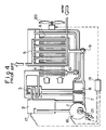
- Fig. 4 is a circuit diagram showing such a system in a prior art apparatus.
- For a better understanding of the present invention, known means for regulating the pressure and flow rate of a refrigerant and a solution in a prior art air-cooled absorption type cooling/heating water generating apparatus to deal with a high embient air temperature will be described with reference to Fig. 4, before describing preferred embodiments of the present invention in detail.
- Referring to Fig. 4, a solution having absorbed a refrigerant evaporated in an
evaporator 5 is fed by asolution circulating pump 9 to flow through a low-temperaturesolution heat exchanger 8 and a high-temperaturesolution heat exchanger 7 into a high-temperature regenerator 1 to be heated therein. After separation of the refrigerant from the solution in aseparator 2, the separated refrigerant in vapor form is fed through a low-temperature regenerator 3 into an air-cooled condenser 4 to be condensed in the condenser 4, and the condensed refrigerant is fed by arefrigerant circulating pump 10 to be recirculated into theevaporator 5. On the other hand, the solution separated from the refrigerant in theseparator 2 is fed through the high-temperaturesolution heat exchanger 7 into the low-temperature regenerator 3 and then into the low-temperaturesolution heat exchanger 8, and, after heat exchange in the high-temperaturesolution heat exchanger 7, the low-temperature regenerator 3 and the low-temperaturesolution heat exchanger 8, the solution is recirculated into an air-cooled absorber 6 cooled by ambient air sucked by acooling fan 20. When the temperature of ambient air rises, a corresponding rise occurs in the temperature of the solution in the high-temperature regenerator 1 in such an apparatus or the internal pressure of theseparator 2 increases in such an apparatus. Atemperature sensor 16 senses the temperature rise of the solution or apressure sensor 17 senses the internal pressure increase of theseparator 2, and the detection output signal of eachsensor control unit 19. In response to the application of the detection output signal from thesensor control unit 19 generates a control signal to increase the rotation speed of thecooling fan 20 so as to enhance the cooling effect thereby preventing the temperature rise or the pressure increase, or thecontrol unit 19 generates a control signal to decrease the quantity of fuel supplied from afuel valve 21 so as to decrease the rate of fuel combustion thereby preventing the temperature rise or the pressure increase. - An embodiment of the present invention will now be described with reference to Fig. 1. In Fig. 1, like reference numerals are used to designate like parts appearing in Fig. 4.
- An embodiment of the air-cooled absorption type cooling/heating water generating apparatus of the present invention includes a circulating system arrangement in which a refrigerant such as water is absorbed in a solution such as lithium bromide solution and, after the steps of removing heat from the solution and heating the solution, the refrigerant is separated from the solution.
- Referring to Fig. 1, the refrigerant is evaporated in an
evaporator 5 by receiving heat from cold water flowing in a direction of the arrow shown in Fig. 1, and the evaporated refrigerant is absorbed in the solution to provide a low-temperature diluted solution. This diluted solution is fed by asolution circulating pump 9 to flow through a low-temperaturesolution heat exchanger 8 and a high-temperaturesolution heat exchanger 7 into a high-temperature regenerator 1 to be heated in the high-temperature regenerator 1. After separation of the refrigerant from the solution in aseparator 2, the separated refrigerant in vapor form is subjected to heat exchange in a low-temperature regenerator 3 and is then condensed in an air-cooled condenser 4. The condensed refrigerent is fed by arefrigerant circulating pump 10 to be recirculated into theevaporator 5. On the other hand, the high-temperature dense solution left after the separation of the refrigerant in theseparator 2 is fed through the high-temperaturesolution heat exchanger 7 into the low-temperature regenerator 3 and then into the low-temperaturesolution heat exchanger 8. After heat exchange in the high-temperaturesolution heat exchanger 7, the low-temperature regenerator 3 and the low-temperaturesolution heat exchanger 8, the solution is recirculated into an air-cooledabsorber 6 which is cooled by ambient air sucked by acooling fan 20 to cool the refrigerant generating absorption heat during absorption. A constant flow rate control valve 11 is disposed in aconduit 22 connected between the high-temperaturesolution heat exchanger 7 and the low-temperature regenerator 3 to control the flow rate of the solution of a medium density, and apressure regulating valve 12 is disposed in aconduit 23 connected between the low-temperature regenerator 3 and the air-cooled condenser 4 to regulate the pressure of the refrigerant vapor. - The operation of the apparatus of the present invention will now be described.
- The
pressure regulating valve 12 is a primary pressure regulating valve. A rise in the temperature of ambient air results in a corresponding reduction of the cooling ability of the air-cooled condenser 4. That is, as a result of the rise in the temperature of ambient air, the internal pressure of the air-cooled condenser 4 increases first, and such a pressure increase occurs succlssively in each of the low-pressure regenerator 3, the high-temperature regenerator 1 and theseparator 2 located upstream of the air-cooled condenser 4. When the internal pressure of theseparator 2 increases beyond a predetermined setting of thepressure regulating valve 12, the valve opening of thepressure regulating valve 12 increases to discharge an excess of the refrigerant vapor generated in the high-temperature regenerator 1 toward the low pressure side. Therefore, the internal pressure of theseparator 2 is always regulated to a level equal to or lower than the predetermined level, so that the temperature of the solution in the high-temperature regenerator 1 does not become excessively high. - The constant flow rate control valve 11 controls the flow rate of the medium-density solution on the basis of the result of detection of the internal pressure difference between the
separator 2 and the low-temperature regenerator 3, so that the flow rate of the medium-density solution can be maintained constant. - Another embodiment of the present invention will be described with reference to Fig. 2.
- Referring to Fig. 2 showing a partial modification of the embodiment shown in Fig. 1, a
fixed orifice 13 is provided in theconduit 23 through which the refrigerant heated in the high-temperature regenerator 1 and separated from the solution in theseparator 2 is fed in vapor form into the low-temperature regenerator 3 and then into the air-cooled condensor 4 after the heat exchange in the low-temperature regenerator 3. A safety valve or arelief valve 14 is disposed in parallel with thefixed orifice 13. - In operation, when the internal pressure of the high-
temperature regenerator 1, hence, that of theseparator 2 increases to exceed a pressure setting of the safety valve orrelief valve 14 due to a temperature rise of ambient air, thevalve 14 acts to discharge the refrigerant vapor to the low pressure side thereby preventing the pressure increase. - Still another embodiment of the present invention will be described with reference to Fig. 3.
- Referring to Fig. 3 showing a partial modification of the embodiment shown in Fig. 2, the
control valve 14 which is actuated by an electrical, oil hydraulic or pneumatic actuator 15 is disposed in parallel with thefixed orifice 13. The apparatus further includes asolution temperature sensor 16 sensing the temperature of the solution in the high-temperature regenerator 1, apressure sensor 17 sensing the internal pressure of theseparator 2, an ambient-air temperature sensor 18 sensing the temperature of ambient air, and acontrol unit 19 receiving the detection output signals of thesensors control valve 14, when at least one of the detection output signals of the sensors indicates that a setting is exceeded. - In operation, when at least one of the detection output signals of the ambient-
air temperature sensor 18, thepressure sensor 17 and thesolution temperature sensor 16 indicates that the detected valve exceeds a predetermined setting due to a temperature rise of ambient air, thecontrol unit 19 generates its control signal to open thecontrol valve 14 thereby preventing the pressure increase. - While preferred embodiments of the present invention have been described above by way of example, the present invention is in no way limited to such specific embodiments, and various changes and modifications may be made therein without departing from the spirit of the present invention.
Claims (6)
means for evaporating a refrigerant, absorbing the evaporated refrigerant in a solution and removing heat from the refrigerant-absorbed solution by cooling with ambient air;
high-temperature regenerating means for heating said refrigerant-absorbed solution;
means for separating said heated refrigerant-absorbed solution into the refrigerant and the solution;
low-temperature regenerating means for subjecting said refrigerant separated in vapor form to heat exchange;
a condenser for condensing said refrigerant vapor;
pump means for circulating said refrigerant-absorbed solution and said condensed refrigerant;
a heat exchanger for subjecting said heat-removed refrigerant-absorbed solution to heat exchange before said refrigerant-absorbed solution is fed into said high-temperature regenerating means and said separating means and also subjecting said separated solution to heat exchange before said separated solution is returned to said refrigerant absorbing and heat removing means;
flow rate regulating means disposed in a conduit of the solution connected between said heat exchanger and said low-temperature regenerating means and
pressure regulating means disposed in a conduit of the evaporated refrigerant connected between said low-temperature regenerating means and said condenser.
Applications Claiming Priority (2)
| Application Number | Priority Date | Filing Date | Title |
|---|---|---|---|
| JP292660/87 | 1987-11-19 | ||
| JP62292660A JPH0674933B2 (en) | 1987-11-19 | 1987-11-19 | Air-cooled absorption chiller / heater |
Publications (2)
| Publication Number | Publication Date |
|---|---|
| EP0317048A1 true EP0317048A1 (en) | 1989-05-24 |
| EP0317048B1 EP0317048B1 (en) | 1991-05-08 |
Family
ID=17784653
Family Applications (1)
| Application Number | Title | Priority Date | Filing Date |
|---|---|---|---|
| EP88306082A Expired - Lifetime EP0317048B1 (en) | 1987-11-19 | 1988-07-04 | Air-cooled absorption type cooling/heating water generating apparatus |
Country Status (4)
| Country | Link |
|---|---|
| US (1) | US4872319A (en) |
| EP (1) | EP0317048B1 (en) |
| JP (1) | JPH0674933B2 (en) |
| DE (1) | DE3862745D1 (en) |
Cited By (3)
| Publication number | Priority date | Publication date | Assignee | Title |
|---|---|---|---|---|
| EP0978694A4 (en) * | 1998-01-29 | 2000-11-08 | Sanyo Electric Co | Absorption type refrigerating machine |
| CN102141320A (en) * | 2011-04-28 | 2011-08-03 | 上海交通大学 | Solar-driven two-stage air-cooled absorption air conditioner |
| WO2014198983A1 (en) | 2013-06-14 | 2014-12-18 | Universitat Politècnica De Catalunya | Machine for air-cooled absorption |
Families Citing this family (17)
| Publication number | Priority date | Publication date | Assignee | Title |
|---|---|---|---|---|
| US4926659A (en) * | 1989-03-30 | 1990-05-22 | Gas Research Institute | Double effect air conditioning system |
| US5009086A (en) * | 1989-03-30 | 1991-04-23 | Gas Research Institute | Passive refrigeration fluids condition |
| JP2747348B2 (en) * | 1989-12-21 | 1998-05-06 | 株式会社日立製作所 | Absorption chiller / heater controller |
| JP3548344B2 (en) * | 1996-07-25 | 2004-07-28 | パロマ工業株式会社 | Air-cooled absorption air conditioner |
| JPH1078265A (en) * | 1996-09-03 | 1998-03-24 | Paloma Ind Ltd | Air-cooled absorption air conditioner |
| WO1998012489A1 (en) * | 1996-09-19 | 1998-03-26 | World Wide Water Company | Purified water supply apparatus |
| JP3943672B2 (en) * | 1997-09-20 | 2007-07-11 | パロマ工業株式会社 | Absorption refrigerator |
| JP4279917B2 (en) * | 1998-06-10 | 2009-06-17 | パロマ工業株式会社 | Absorption refrigerator |
| JP2000028236A (en) | 1998-07-13 | 2000-01-28 | Paloma Ind Ltd | Absorption type refrigerating machine |
| JP2000028229A (en) | 1998-07-13 | 2000-01-28 | Paloma Ind Ltd | Absorption refrigerating machine |
| JP2000035261A (en) | 1998-07-15 | 2000-02-02 | Paloma Ind Ltd | Absorption freezer |
| JP2002371598A (en) * | 2001-06-15 | 2002-12-26 | Hitachi Ltd | Fresh water generator |
| CN104989472B (en) * | 2014-05-28 | 2018-11-06 | 李华玉 | Combined cycle energy supplying system |
| CN104929704B (en) * | 2014-05-28 | 2018-11-06 | 李华玉 | Combined cycle energy supplying system |
| CN105019954B (en) * | 2014-05-28 | 2018-11-06 | 李华玉 | Combined cycle energy supplying system |
| CN104963733B (en) * | 2014-05-28 | 2018-11-06 | 李华玉 | Combined cycle energy supplying system |
| US12520452B2 (en) | 2022-05-04 | 2026-01-06 | Hoffman Enclosures Inc. | Replaceable pump unit for cooling systems |
Citations (3)
| Publication number | Priority date | Publication date | Assignee | Title |
|---|---|---|---|---|
| US4454726A (en) * | 1982-01-06 | 1984-06-19 | Hitachi, Ltd. | Control device of absorption type cold and warm water system |
| US4563882A (en) * | 1984-06-20 | 1986-01-14 | Hitachi, Ltd. | Air cooling type absorption cooler |
| EP0216629A2 (en) * | 1985-09-24 | 1987-04-01 | Yazaki Corporation | Air-cooled absorption type water cooling/heating apparatus |
Family Cites Families (2)
| Publication number | Priority date | Publication date | Assignee | Title |
|---|---|---|---|---|
| US4646541A (en) * | 1984-11-13 | 1987-03-03 | Columbia Gas System Service Corporation | Absorption refrigeration and heat pump system |
| US4691528A (en) * | 1985-08-15 | 1987-09-08 | Yazaki Corporation | Air-cooled absorption type water cooling/heating apparatus |
-
1987
- 1987-11-19 JP JP62292660A patent/JPH0674933B2/en not_active Expired - Fee Related
-
1988
- 1988-06-28 US US07/212,617 patent/US4872319A/en not_active Expired - Lifetime
- 1988-07-04 DE DE8888306082T patent/DE3862745D1/en not_active Expired - Lifetime
- 1988-07-04 EP EP88306082A patent/EP0317048B1/en not_active Expired - Lifetime
Patent Citations (3)
| Publication number | Priority date | Publication date | Assignee | Title |
|---|---|---|---|---|
| US4454726A (en) * | 1982-01-06 | 1984-06-19 | Hitachi, Ltd. | Control device of absorption type cold and warm water system |
| US4563882A (en) * | 1984-06-20 | 1986-01-14 | Hitachi, Ltd. | Air cooling type absorption cooler |
| EP0216629A2 (en) * | 1985-09-24 | 1987-04-01 | Yazaki Corporation | Air-cooled absorption type water cooling/heating apparatus |
Cited By (5)
| Publication number | Priority date | Publication date | Assignee | Title |
|---|---|---|---|---|
| EP0978694A4 (en) * | 1998-01-29 | 2000-11-08 | Sanyo Electric Co | Absorption type refrigerating machine |
| CN102141320A (en) * | 2011-04-28 | 2011-08-03 | 上海交通大学 | Solar-driven two-stage air-cooled absorption air conditioner |
| CN102141320B (en) * | 2011-04-28 | 2013-03-20 | 上海交通大学 | Solar-driven two-stage air-cooled absorption air conditioner |
| WO2014198983A1 (en) | 2013-06-14 | 2014-12-18 | Universitat Politècnica De Catalunya | Machine for air-cooled absorption |
| US10527324B2 (en) | 2013-06-14 | 2020-01-07 | Universitat Politècnica De Catalunya | Machine for air-cooled absorption |
Also Published As
| Publication number | Publication date |
|---|---|
| DE3862745D1 (en) | 1991-06-13 |
| US4872319A (en) | 1989-10-10 |
| JPH0674933B2 (en) | 1994-09-21 |
| JPH01134177A (en) | 1989-05-26 |
| EP0317048B1 (en) | 1991-05-08 |
Similar Documents
| Publication | Publication Date | Title |
|---|---|---|
| US4872319A (en) | Air-cooled absorption type cooling/heating water generating apparatus | |
| US3426547A (en) | Control of absorption refrigeration systems | |
| US3990264A (en) | Refrigeration heat recovery system | |
| US4691525A (en) | Method of operating an absorption heat pump or refrigerator, and an absorption heat pump or refrigerator | |
| US4534180A (en) | Absorption refrigeration system with solution flow control | |
| US3550391A (en) | Absorption refrigeration system having compensated dilution control | |
| US3620036A (en) | Solution concentration control in absorption refrigeration systems | |
| JP3448680B2 (en) | Absorption air conditioner | |
| US3334492A (en) | Absorption refrigeration systems | |
| US3279207A (en) | Absorption refrigeration systems | |
| KR100324561B1 (en) | Apparatus for preventing high pressure in absorption heat pump and method thereof | |
| US4254631A (en) | Method and apparatus for satisfying heating and cooling demands and control therefor | |
| US4254632A (en) | Method and apparatus for satisfying heating and cooling demands and control therefor | |
| KR930004387B1 (en) | Drain Control of Absorption Chiller | |
| JP2501947B2 (en) | Refrigeration equipment | |
| JP3303440B2 (en) | Cold water temperature control method for cold water generator | |
| JPH0668426B2 (en) | Air-cooled absorption chiller / heater | |
| CA1122024A (en) | Method and apparatus for satisfying heating and cooling demands and control therefor | |
| JPH087314Y2 (en) | refrigerator | |
| JP3321911B2 (en) | Absorption refrigeration equipment | |
| JPS58160780A (en) | Controller for absorption refrigerator | |
| JPS58117978A (en) | Controller for absorption refrigerator | |
| JPS5921957A (en) | Absorption cold and hot water machine | |
| JPS58160782A (en) | Controller for absorption refrigerator | |
| JPH03158665A (en) | Absorption cold/hot water apparatus and operation thereof |
Legal Events
| Date | Code | Title | Description |
|---|---|---|---|
| PUAI | Public reference made under article 153(3) epc to a published international application that has entered the european phase |
Free format text: ORIGINAL CODE: 0009012 |
|
| AK | Designated contracting states |
Kind code of ref document: A1 Designated state(s): DE FR SE |
|
| 17P | Request for examination filed |
Effective date: 19890704 |
|
| 17Q | First examination report despatched |
Effective date: 19900117 |
|
| GRAA | (expected) grant |
Free format text: ORIGINAL CODE: 0009210 |
|
| AK | Designated contracting states |
Kind code of ref document: B1 Designated state(s): DE FR SE |
|
| REF | Corresponds to: |
Ref document number: 3862745 Country of ref document: DE Date of ref document: 19910613 |
|
| ET | Fr: translation filed | ||
| PLBE | No opposition filed within time limit |
Free format text: ORIGINAL CODE: 0009261 |
|
| STAA | Information on the status of an ep patent application or granted ep patent |
Free format text: STATUS: NO OPPOSITION FILED WITHIN TIME LIMIT |
|
| 26N | No opposition filed | ||
| EAL | Se: european patent in force in sweden |
Ref document number: 88306082.4 |
|
| PGFP | Annual fee paid to national office [announced via postgrant information from national office to epo] |
Ref country code: DE Payment date: 20050630 Year of fee payment: 18 |
|
| PGFP | Annual fee paid to national office [announced via postgrant information from national office to epo] |
Ref country code: SE Payment date: 20050706 Year of fee payment: 18 |
|
| PGFP | Annual fee paid to national office [announced via postgrant information from national office to epo] |
Ref country code: FR Payment date: 20050708 Year of fee payment: 18 |
|
| PG25 | Lapsed in a contracting state [announced via postgrant information from national office to epo] |
Ref country code: SE Free format text: LAPSE BECAUSE OF NON-PAYMENT OF DUE FEES Effective date: 20060705 |
|
| PG25 | Lapsed in a contracting state [announced via postgrant information from national office to epo] |
Ref country code: DE Free format text: LAPSE BECAUSE OF NON-PAYMENT OF DUE FEES Effective date: 20070201 |
|
| EUG | Se: european patent has lapsed | ||
| REG | Reference to a national code |
Ref country code: FR Ref legal event code: ST Effective date: 20070330 |
|
| PG25 | Lapsed in a contracting state [announced via postgrant information from national office to epo] |
Ref country code: FR Free format text: LAPSE BECAUSE OF NON-PAYMENT OF DUE FEES Effective date: 20060731 |