EP0216629A2 - Air-cooled absorption type water cooling/heating apparatus - Google Patents
Air-cooled absorption type water cooling/heating apparatus Download PDFInfo
- Publication number
- EP0216629A2 EP0216629A2 EP86307287A EP86307287A EP0216629A2 EP 0216629 A2 EP0216629 A2 EP 0216629A2 EP 86307287 A EP86307287 A EP 86307287A EP 86307287 A EP86307287 A EP 86307287A EP 0216629 A2 EP0216629 A2 EP 0216629A2
- Authority
- EP
- European Patent Office
- Prior art keywords
- cooling
- air
- separator
- heating
- solution
- Prior art date
- Legal status (The legal status is an assumption and is not a legal conclusion. Google has not performed a legal analysis and makes no representation as to the accuracy of the status listed.)
- Granted
Links
Images


Classifications
-
- F—MECHANICAL ENGINEERING; LIGHTING; HEATING; WEAPONS; BLASTING
- F25—REFRIGERATION OR COOLING; COMBINED HEATING AND REFRIGERATION SYSTEMS; HEAT PUMP SYSTEMS; MANUFACTURE OR STORAGE OF ICE; LIQUEFACTION SOLIDIFICATION OF GASES
- F25B—REFRIGERATION MACHINES, PLANTS OR SYSTEMS; COMBINED HEATING AND REFRIGERATION SYSTEMS; HEAT PUMP SYSTEMS
- F25B29/00—Combined heating and refrigeration systems, e.g. operating alternately or simultaneously
- F25B29/006—Combined heating and refrigeration systems, e.g. operating alternately or simultaneously of the sorption type system
-
- F—MECHANICAL ENGINEERING; LIGHTING; HEATING; WEAPONS; BLASTING
- F25—REFRIGERATION OR COOLING; COMBINED HEATING AND REFRIGERATION SYSTEMS; HEAT PUMP SYSTEMS; MANUFACTURE OR STORAGE OF ICE; LIQUEFACTION SOLIDIFICATION OF GASES
- F25B—REFRIGERATION MACHINES, PLANTS OR SYSTEMS; COMBINED HEATING AND REFRIGERATION SYSTEMS; HEAT PUMP SYSTEMS
- F25B15/00—Sorption machines, plants or systems, operating continuously, e.g. absorption type
- F25B15/008—Sorption machines, plants or systems, operating continuously, e.g. absorption type with multi-stage operation
-
- F—MECHANICAL ENGINEERING; LIGHTING; HEATING; WEAPONS; BLASTING
- F25—REFRIGERATION OR COOLING; COMBINED HEATING AND REFRIGERATION SYSTEMS; HEAT PUMP SYSTEMS; MANUFACTURE OR STORAGE OF ICE; LIQUEFACTION SOLIDIFICATION OF GASES
- F25B—REFRIGERATION MACHINES, PLANTS OR SYSTEMS; COMBINED HEATING AND REFRIGERATION SYSTEMS; HEAT PUMP SYSTEMS
- F25B15/00—Sorption machines, plants or systems, operating continuously, e.g. absorption type
- F25B15/02—Sorption machines, plants or systems, operating continuously, e.g. absorption type without inert gas
- F25B15/06—Sorption machines, plants or systems, operating continuously, e.g. absorption type without inert gas the refrigerant being water vapour evaporated from a salt solution, e.g. lithium bromide
-
- Y—GENERAL TAGGING OF NEW TECHNOLOGICAL DEVELOPMENTS; GENERAL TAGGING OF CROSS-SECTIONAL TECHNOLOGIES SPANNING OVER SEVERAL SECTIONS OF THE IPC; TECHNICAL SUBJECTS COVERED BY FORMER USPC CROSS-REFERENCE ART COLLECTIONS [XRACs] AND DIGESTS
- Y02—TECHNOLOGIES OR APPLICATIONS FOR MITIGATION OR ADAPTATION AGAINST CLIMATE CHANGE
- Y02A—TECHNOLOGIES FOR ADAPTATION TO CLIMATE CHANGE
- Y02A30/00—Adapting or protecting infrastructure or their operation
- Y02A30/27—Relating to heating, ventilation or air conditioning [HVAC] technologies
-
- Y—GENERAL TAGGING OF NEW TECHNOLOGICAL DEVELOPMENTS; GENERAL TAGGING OF CROSS-SECTIONAL TECHNOLOGIES SPANNING OVER SEVERAL SECTIONS OF THE IPC; TECHNICAL SUBJECTS COVERED BY FORMER USPC CROSS-REFERENCE ART COLLECTIONS [XRACs] AND DIGESTS
- Y02—TECHNOLOGIES OR APPLICATIONS FOR MITIGATION OR ADAPTATION AGAINST CLIMATE CHANGE
- Y02B—CLIMATE CHANGE MITIGATION TECHNOLOGIES RELATED TO BUILDINGS, e.g. HOUSING, HOUSE APPLIANCES OR RELATED END-USER APPLICATIONS
- Y02B30/00—Energy efficient heating, ventilation or air conditioning [HVAC]
- Y02B30/62—Absorption based systems
Definitions
- the present invention relates to an air-cooled absorption type water cooling/heating apparatus in which air is used as a cooling medium for cooling both a condenser for liquefying gaseous refrigerant separated in a separator and an absorber which is supplied with a thick salt solution for absorbing gaseous refrigerant evaporated in an evaporator.
- a water-cooled absorption type water cooling/heating apparatus has been known in which a condenser and an absorber are cooled by water.
- This apparatus has a cooling system which employs a heat exchanger for chilling water by making use of heat absorption caused by evaporation of a liquid-phase refrigerant in the evaporator.
- the apparatus has a cooling/heating change-over valve which permits, when the apparatus is used in heating mode, the evaporator to be supplied with hot refrigerant gas so that the heat exchanger functions as a water heater.
- the heat exchanger is serveable both as a water cooler and a water heater, depending on the operation mode of the apparatus. This means that the provision of independent heat exchangers for cooling and heating purposes is not necessary.
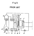
- FIG. 5 Known also is an air-cooled absorption type water cooling/heating apparatus.
- This apparatus has a cooling cycle which is constituted by, as shown in Fig. 5, a high-temperature regenerator 1' for heating a thin salt solution which has absorbed a refrigerant, a separator 2' for fractionating the heated solution into refrigerant vapor and a solution of an intermediate thickness, a low-temperature regenerator 4' for heating the solution of intermediate thickness by the heat produced as a result of condensation of the refrigerant gas, an air-cooled condenser 6' for liquefying the refrigerant gas from the low-temperature regenerator 4', an evaporator 7' in which the liquefied refrigerant from the condenser 6' is evaporated so as to chill water, an absorber 8' in which the refrigerant gas from the evaporator 7' is absorbed in thick solution supplied from the low-temperature regenerator 4', and a pump 9' which pumps up the thin solution which has
- the apparatus further has a cooling/heatig change-over valve 17' provided in a pipe between the separator 2' and the evaporator 7'.
- a cooling/heatig change-over valve 17' provided in a pipe between the separator 2' and the evaporator 7'.
- Fig. 6 shows still another known water cooling/heating apparatus which has, in addition to the constituents of the apparatus shown in Fig. 5, a water heater 11' and a heat source 10' for the water heater 11'.
- a three-way valve 12' is switchable between two positions such as to open either a flow passage A or a flow passage B.
- the heat exchanger of the evaporator 7' functions both for cooling and heating purposes.
- an effort for attaining high efficiency of cooling of the condenser 6'and the absorber 8' by air results in a reduction of the heating capacity of the apparatus in heating mode, due to an increase in the natural heat radiation from the condenser 6' and the absorber 8' to the ambient air.
- An object of the invention is to provide an air-cooled absorption type water cooling/heating apparatus which is capable of producing sufficient cooling power and heating power with a single heat source and which permits an easy switching between the cooling mode operation and the heating mode operation.
- an air-cooled absorption type water cooling/heating apparatus comprising: a cooling circulation system including, a high-temperature regenerator in which a thin solution which has absorbed a refrigerant is heated so that refrigerant vapor and thick solution are regenerated, a separator for separating the refrigerant vapor and the thick solution from each other, an air-cooled condenser for condensing the refrigerant vapor into liquid phase by air-cooling, an evaporator in which the condensed liquid refrigerant is evaporated by heat derived from a heat exchanger leading to a heat radiator, thereby cooling a heat transfer medium circulated through the heat exchanger, an absorber in which the refrigerant vapor generated in the evaporator in the thick slution introduced from the separator, the absorber being air-cooled so that the heat produced as a result of the absorption is carried away by the cooling air, and a pump for supplying the thin solution which is
- the apparatus in accordance with the present invention offers the following advantages.
- an air-cooled absorption type water cooling/heating apparatus of the invention has the following parts: a high-temperature regenerator 1 in which a thin solution such as LiBr which has absorbed a refrigerant such as water is heated so as to be fractionated into refrigerant vapor and an intermediate-thickness solution; a separator 2 in which the refrigerant vapor and the intermediate thickness solution are separated from each other; a high-temperature heat exchanger 3; a low-temperature regenerator 4 in which the intermediate thickness solution, which has been cooled through heat exchange with low-temperature thin solution in the high-temperature heat exchanger 3, is heated by the refrigerant vapor separated in the separator 2, so that the intermediate thickness solution is fractionated into refrigerant vapor and thick solution; a low-temperature heat exchanger 5; a condenser 6 for liquefying the refrigerant vapor produced in the low-temperature regenerator 4 and for cooling the refrigerant which has been liquefied through
- the thus generated chilled water and warmed water are selectively delivered to a service line leading to a heat radiator (not shown), in accordance with the position of a three-way valve 12 which is disposed in the line between the evaporator 7 and the water heater 11.
- the circulation of the water as the heat transfer medium is effected by a water circulation pump 13 which is disposed upstream of the three-way valve 12.
- the construction of the intermediate thickness solution flow control valve 14 and the refrigerant flow control valve 15 have substantially the same construction which is schematically illustrated in Fig. 2.
- the valve has an outlet pipe 20 and an inlet pipe 21.
- the outlet pipe 20 is connected to the low-temperature regenerator 4, whereas, in case of the refrigerant flow control valve 15, the outlet pipe 20 is connected to the condenser 6.
- the inlet pipe 21 is connected to the intemediate thickness solution line 26 through which the intermediate thickness solution cooled through the high-temperature heat exchanger is delivered, in the case of the intermedi ate thickness solution flow control valve 14.
- the inlet pipe 21 is connected to the liquid refrigerant line 27 through which the refrigerant liquefied in the low-temperature regenerator 4 is supplied.
- the valve has another connection 22 which is connected to the condenser 6 both in the cases of the intermediate thickness solution flow control valve 14 and the refrigerant flow control valve 15.
- the valve also has a diaphragm 24 which separates the space in the valve into a chamber communicating with the inlet pipe 21 and a chamber communicating with the connection 22.
- a pressure differential is developed across the diaphragm 24 between the pressure derived from the inlet pipe 21 and the pressure in the condenser 6 transmitted through the connection 22, so that the diaphragm 24 is deflected in accordance with the pressure differential thereby moving a valve member 23 into and out of contact with a valve seat formed on the end of the outlet pipe 20.
- the diaphragm 24 is backed up by an adjustable spring 25 which has a function for adjusting the valve closing pressure in order to ensure perfect closing of the valve.
- the apparatus shown in Fig. 1 employs a single heat source 10 for heating the high-temperature regenerator 1.
- a burner for burning a fuel is used as the heat source 10.
- a reference numeral 16 designates a cooling air blower for discharge the condensation heat in the condenser 6 and the absorbed heat in the absorber 8 into the atmosphere during operation of the apparatus in the cooling mode.
- the apparatus further has a solution check valve which prevents the solution from flowing back to the absorber 8 from the low-temperature heat exchanger 5 when the solution pump 9 is stopped, and a solution bypass pipe 19 through which the solution flows during operation in the heating mode.
- the communication between the inlet pipe 21 and the outlet 20 is selectively interrupted by the valve member 23 which moves in response to the pressure differential between the condenser 6 and the inlet 21.
- the three-way valve 12 is switched to cause the water to flow as indicated by the arrow A in Fig. 1, so that the water is introduced into the water heater 11.
- the temperature of the water at the outlet of the water heater 11 is adjusted to range between 50 and 60°C. In this state, the pressure in the separator 2 ranges between 100 and 160 mmHg Abs.
- the intermediate thickness solution flow control valve 14 and the refigerant flow control valve 15 are adjusted such that they open when the pressure at the inlet pipe 21 is increased to 200 to 250 mmHg Abs, so that the solution and the refrigerant vapor heated in the high-temperature regenerator 1 are prevented from flowing into the low-temperature regenerator 4 and the condenser 6.
- the efficiency of the whole apparatus in the heating mode is improved significantly.
- the operation in the cooling mode is initiated by switching the three-way valve 12 so as to cause the water to flow in the direction indicated by the arrow B.
- the water is chilled in the heat exchanger of the evaporator 7, as in the case of the known absorption type water cooling/heating apparatus.
- the pressure in the separator 2 usually ranges between 500 and 1500 mmHg Abs, so that the intermediate thickness solution flow control valve 14 and the refrigerant flow control valve 14 are kept open.
- the differential-pressure responsive type valve used as the intermediate thickness solution flow control valve 14 and the refrigerant flow control valve 15 may be substituted by other types of valve which are operative in response to cooling/hea ting control signals, e.g., a solenoid valve or a modutrol valve.
- the three-way valve 12 for conducting the change-over between the cooling and heating modes can be substituted by other types of valve such as a combination of two-way valves or a manual valve
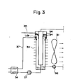
- Fig. 3 shows an air-cooled fin-type absorber 313 suitable for use in the apparatus of the invention.
- This absorber is of "vertical flow liquid-film type air-cooled absorber" having a tubular body which is provided on the outer peripheral surface thereof with fins 313 for improving the efficiency of heat exchange upon contact with the cooling air.
- the thick solution which has been cooled through heat exchange with the thin solution in the heat exchanger 34, is made to flow down along the inner wall surface of the tubular body.
- the air-cooled fin-type absorber 313 is provided at an upper portion thereof with a dam.
- the thick solution which has been separated in the separator 2, is supplied through the line 317 via the heat exchanger 34 into the space defined by the dam, and the overflow of the thick solution over the dam is made to flow along the inner wall surface of the tubular member, in the form of a thin liquid film.
- the thick solution is cooled as a result of heat exchange across the wall of the tubular member of the absorber with the cooling air which is induced by the blower 311.
- the absorber 313 receives an evaporator pipe 314 with an outer surface which is suitably roughened or provided with convexities and concavities so as to produce a greater surface area, thus promoting the evaporation of the liquid refrigerant.
- the water as the heat transfer medium is circulated through this pipe 314.
- the refrigerant condensed in the condenser is introduced into the absorber 313 through a line 315.
- Another dam 316 provided to face an upper end portion of the evaporator tube 314 causes the liquid refrigerant to flow along the outer surface of the eaporator tube 314, thus offering a high efficiency of heat exchange between the liquid refrigerant and the water across the wall of the evaporator tube 314.
- the invention of this application can employ a vertical flow liquid-film type air-cooled absorber in which the absorber and the evaporator in the conventional apparatus are combined to realize a compact construction.
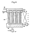
- the invention can employ a plurality of the vertical flow liquid-film type air-cooled absorber arranged in parallel with each other. These absorbers are equipped with common dams so that the liquid refrigerant and the solution supplied through the lines 315 and 317 are made to flow down along respective surfaces of the parallel vertical flow liquid-film type air-cooled absorbers, thus attaining greater refrigeration power.
- any desired refrigeration capacity can be obtained by suitably selecting the number of the vertical flow liquid-fielm type air-cooled absorbers which are connected in parallel.
- the operation of the air-cooled absorber is as follows.
- the thick solution which flows down from the upper end of the absorber 313 absorbs the refrigerant which has been evaporated on the surface of the evaporator pipe 314 and is gradually heated due to generation of the absorption heat, so that the absorption power tends to be decreased.
- the absorber 313 is constructed such as to permit a direct heat exchange with the air, the solution which has absorbed the refrigerant is effectively cooled even though the heat exchange area is small, thus recovering or maintaining the absorption power.
- the vertical flow liquid-film type air-cooled absorber enables direct cooling by the air, so that the temperature difference between the cooling air and the solution which has absorbed the refrigerant is maintained sufficiently small, thus assuring a high absorption efficiency.
- a high evaporation efficiency is attained because the refrigerant vapor generated on the evaporator pipe can reach the absorber without being encountered by substantial flow resistance, thanks to the construction in which the evaporator and the absorber are integrated such that they are positioned adjacent to each other.
- the vertical flow liquid-film type air-cooled absorber can have reduced heat exchanging surface areas, contributing to a reduction in the size of the air-cooled absorption type water cooling/heating apparatus, as well as to the reduction in the production cost.
Landscapes
- Engineering & Computer Science (AREA)
- Physics & Mathematics (AREA)
- Mechanical Engineering (AREA)
- Thermal Sciences (AREA)
- General Engineering & Computer Science (AREA)
- Chemical & Material Sciences (AREA)
- Materials Engineering (AREA)
- Sorption Type Refrigeration Machines (AREA)
Abstract
Description
- The present invention relates to an air-cooled absorption type water cooling/heating apparatus in which air is used as a cooling medium for cooling both a condenser for liquefying gaseous refrigerant separated in a separator and an absorber which is supplied with a thick salt solution for absorbing gaseous refrigerant evaporated in an evaporator.
- A water-cooled absorption type water cooling/heating apparatus has been known in which a condenser and an absorber are cooled by water. This apparatus has a cooling system which employs a heat exchanger for chilling water by making use of heat absorption caused by evaporation of a liquid-phase refrigerant in the evaporator. The apparatus has a cooling/heating change-over valve which permits, when the apparatus is used in heating mode, the evaporator to be supplied with hot refrigerant gas so that the heat exchanger functions as a water heater. In this apparatus, therefore, the heat exchanger is serveable both as a water cooler and a water heater, depending on the operation mode of the apparatus. This means that the provision of independent heat exchangers for cooling and heating purposes is not necessary.
- Known also is an air-cooled absorption type water cooling/heating apparatus. This apparatus has a cooling cycle which is constituted by, as shown in Fig. 5, a high-temperature regenerator 1' for heating a thin salt solution which has absorbed a refrigerant, a separator 2' for fractionating the heated solution into refrigerant vapor and a solution of an intermediate thickness, a low-temperature regenerator 4' for heating the solution of intermediate thickness by the heat produced as a result of condensation of the refrigerant gas, an air-cooled condenser 6' for liquefying the refrigerant gas from the low-temperature regenerator 4', an evaporator 7' in which the liquefied refrigerant from the condenser 6' is evaporated so as to chill water, an absorber 8' in which the refrigerant gas from the evaporator 7' is absorbed in thick solution supplied from the low-temperature regenerator 4', and a pump 9' which pumps up the thin solution which has absorbed the refrigerant into the high-temperature regenerator 1'. The apparatus further has a cooling/heatig change-over valve 17' provided in a pipe between the separator 2' and the evaporator 7'. When this valve 17' is opened, the heat exchanger of the evaporator 7', which constitutes a water cooler in the cooling cycle, functions as a water heater. In this case, therefore, the above-mentioned constituents form a heating cycle.
- Fig. 6 shows still another known water cooling/heating apparatus which has, in addition to the constituents of the apparatus shown in Fig. 5, a water heater 11' and a heat source 10' for the water heater 11'. A three-way valve 12' is switchable between two positions such as to open either a flow passage A or a flow passage B. In the apparatus shown in Fig. 5, the heat exchanger of the evaporator 7' functions both for cooling and heating purposes. Unfortunately, an effort for attaining high efficiency of cooling of the condenser 6'and the absorber 8' by air results in a reduction of the heating capacity of the apparatus in heating mode, due to an increase in the natural heat radiation from the condenser 6' and the absorber 8' to the ambient air. The apparatus shown in Fig. 6, therefore, incorporates the water heater 11' and the heat source 10' which in combination assist the evaporator in heating the water so as to compensate for the reduction in the heating power experienced with the apparatus shown in Fig. 5. The apparatus shown in Fig. 6, however, necessitates two heat sources: namely, the heat source for heating the high-temperature regenerator in the cooling mode and the heat source 10' for the water heater 11', with the result that the construction of the apparatus as a whole is complic ated and the production cost is raised.
- An object of the invention is to provide an air-cooled absorption type water cooling/heating apparatus which is capable of producing sufficient cooling power and heating power with a single heat source and which permits an easy switching between the cooling mode operation and the heating mode operation.
- To this end, according to one aspect of the invention, there is provided an air-cooled absorption type water cooling/heating apparatus comprising: a cooling circulation system including, a high-temperature regenerator in which a thin solution which has absorbed a refrigerant is heated so that refrigerant vapor and thick solution are regenerated, a separator for separating the refrigerant vapor and the thick solution from each other, an air-cooled condenser for condensing the refrigerant vapor into liquid phase by air-cooling, an evaporator in which the condensed liquid refrigerant is evaporated by heat derived from a heat exchanger leading to a heat radiator, thereby cooling a heat transfer medium circulated through the heat exchanger, an absorber in which the refrigerant vapor generated in the evaporator in the thick slution introduced from the separator, the absorber being air-cooled so that the heat produced as a result of the absorption is carried away by the cooling air, and a pump for supplying the thin solution which is formed from the thin solution as a result of absorption of the refrigerant vapour into the high-temperature regenerator; a heating circulation system including a heat exchanger provided in the separator and leading to the heat radiator; and means for closing a line between the separator and the condenser and a line between the separator and the absorber during operation in the heating mode.
- Briefly, the apparatus in accordance with the present invention offers the following advantages.
- (i) The production cost is lowered because the cooling and heating modes of operation are realized by a single heat source.
- (ii) The switching between the cooling mode operation and the heating mode operation is carried out simply by switching over of the water circulation line between that for the cooling and that for the heating.
- (iii) Since the intermediate-thickness solution flow control valve and the refrigerant flow control valve are simple automatic control valve capable of operating in response to pressures therein, it is not necessary to employ specific control valves such as a solenoid valve mechanism, modutrol valve mechanism, and so forth. This contributes to a reduction in the cost required for the control.
- The above and other objects, features and advantages of the invention will become clear from the following description of the preferred embodiment when the same is read in conjunction with the accompanying drawings.
- Fig. 1 is a diagrammatic illustration of an air-cooled absorption type water cooling/heating apparatus in accordance with the present invention;
- Fig. 2 is a schematic illustration of a valve for controlling the flow rate of a refrigerant and a solution which has absorbed the refrigerant;
- Fig. 3 is an illustration of an air-cooled absorber and an evaporator incorporated in the apparatus of the invention;
- Fig. 4 is an illustration of a modification in which the air-cooled absorber and the evaporator shown in Fig. 4 are constructed from multiple parallel units;
- Fig. 5 is a diagrammatic illustration of a conventional air-cooled absorption type water cooling/heating apparatus; and
- Fig. 6 is a diagrammatic illustration of another conventional air-cooled absorption type water cooling/heating apparatus.
- A preferred embodiment of the invention will be described hereinunder with reference to the accompanying drawings.
- Referring first to Fig. 1, an air-cooled absorption type water cooling/heating apparatus of the invention has the following parts: a high-
temperature regenerator 1 in which a thin solution such as LiBr which has absorbed a refrigerant such as water is heated so as to be fractionated into refrigerant vapor and an intermediate-thickness solution; aseparator 2 in which the refrigerant vapor and the intermediate thickness solution are separated from each other; a high-temperature heat exchanger 3; a low-temperature regenerator 4 in which the intermediate thickness solution, which has been cooled through heat exchange with low-temperature thin solution in the high-temperature heat exchanger 3, is heated by the refrigerant vapor separated in theseparator 2, so that the intermediate thickness solution is fractionated into refrigerant vapor and thick solution; a low-temperature heat exchanger 5; acondenser 6 for liquefying the refrigerant vapor produced in the low-temperature regenerator 4 and for cooling the refrigerant which has been liquefied through the low-temperature regenerator 4; anevaporator 7 in which the refrigerant liquefied in the condenser is made to evapotrate through heat exchange with water as a load thus chilling the water; aseparator 8 for causing the refrigerant vapor generated in theevaporator 7 to be absorbed in thick solution which has been generated in the low-temperature regenerator 4 and cooled through heat exchange with the cold thin solution in the low-temperature regenerator 5; and asolution pump 9 which pumps up the thin solution from theabsorber 8 to the high-temperature regenerator 1. These constituents in combination provide closed loops for cooling and heating cycles. Namely, chilled water which serves as a cold heat source is generated in the heat exchanger of theevaporator 7 as a result of heat exchange between water and the refrigerant which is being evaporated in theevaporator 7, while warmed water which serves as a high-temperature heat source is generated in a high-temperature regenerator 11 provided in theseparator 2, since the water is heated by the heat which is produced as the refrigerant vapor introduced from the high-temperature regenerator is condensed into liquid phase within theseparator 2. The thus generated chilled water and warmed water are selectively delivered to a service line leading to a heat radiator (not shown), in accordance with the position of a three-way valve 12 which is disposed in the line between theevaporator 7 and the water heater 11. The circulation of the water as the heat transfer medium is effected by awater circulation pump 13 which is disposed upstream of the three-way valve 12. An intermediate thickness solutionflow control valve 14, which is adapted to automatically open and close in response to the pressure differential between theseparator 2 and thecondenser 6, is provided in theline 26 through which the intermediate thickness solution is supplied to the low-temperature regenerator 4. A refrigerantflow control valve 15, capable of automatically opening and closing in response to the pressure differential between theseparator 2 and thecondenser 6, is disposed in theline 27 through which the refrigerant liquefied through heat exchange within the low-temperature regenerator 4 is introduced into thecondenser 6. - The construction of the intermediate thickness solution
flow control valve 14 and the refrigerantflow control valve 15 have substantially the same construction which is schematically illustrated in Fig. 2. The valve has anoutlet pipe 20 and an inlet pipe 21. In case of the intermediate thickness solutionflow control valve 14, theoutlet pipe 20 is connected to the low-temperature regenerator 4, whereas, in case of the refrigerantflow control valve 15, theoutlet pipe 20 is connected to thecondenser 6. On the other hand, the inlet pipe 21 is connected to the intemediatethickness solution line 26 through which the intermediate thickness solution cooled through the high-temperature heat exchanger is delivered, in the case of the intermedi ate thickness solutionflow control valve 14. In case of the refrigerantflow control valve 15, the inlet pipe 21 is connected to theliquid refrigerant line 27 through which the refrigerant liquefied in the low-temperature regenerator 4 is supplied. The valve has another connection 22 which is connected to thecondenser 6 both in the cases of the intermediate thickness solutionflow control valve 14 and the refrigerantflow control valve 15. The valve also has adiaphragm 24 which separates the space in the valve into a chamber communicating with the inlet pipe 21 and a chamber communicating with the connection 22. Therefore, a pressure differential is developed across thediaphragm 24 between the pressure derived from the inlet pipe 21 and the pressure in thecondenser 6 transmitted through the connection 22, so that thediaphragm 24 is deflected in accordance with the pressure differential thereby moving avalve member 23 into and out of contact with a valve seat formed on the end of theoutlet pipe 20. Thediaphragm 24 is backed up by anadjustable spring 25 which has a function for adjusting the valve closing pressure in order to ensure perfect closing of the valve. - The apparatus shown in Fig. 1 employs a
single heat source 10 for heating the high-temperature regenerator 1. In general, a burner for burning a fuel is used as theheat source 10. Areference numeral 16 designates a cooling air blower for discharge the condensation heat in thecondenser 6 and the absorbed heat in theabsorber 8 into the atmosphere during operation of the apparatus in the cooling mode. The apparatus further has a solution check valve which prevents the solution from flowing back to theabsorber 8 from the low-temperature heat exchanger 5 when thesolution pump 9 is stopped, and asolution bypass pipe 19 through which the solution flows during operation in the heating mode. - Thus, in each of the intermediate thickness solution
flow control valve 14 and the refrigerantflow control valve 15, the communication between the inlet pipe 21 and theoutlet 20 is selectively interrupted by thevalve member 23 which moves in response to the pressure differential between thecondenser 6 and the inlet 21. For operating the apparatus in the heating mode, the three-way valve 12 is switched to cause the water to flow as indicated by the arrow A in Fig. 1, so that the water is introduced into the water heater 11. The temperature of the water at the outlet of the water heater 11 is adjusted to range between 50 and 60°C. In this state, the pressure in theseparator 2 ranges between 100 and 160 mmHg Abs. In this case, therefore, the intermediate thickness solutionflow control valve 14 and the refigerantflow control valve 15 are adjusted such that they open when the pressure at the inlet pipe 21 is increased to 200 to 250 mmHg Abs, so that the solution and the refrigerant vapor heated in the high-temperature regenerator 1 are prevented from flowing into the low-temperature regenerator 4 and thecondenser 6. In consequence, the efficiency of the whole apparatus in the heating mode is improved significantly. - On the other hand, the operation in the cooling mode is initiated by switching the three-
way valve 12 so as to cause the water to flow in the direction indicated by the arrow B. In this case, therefore, the water is chilled in the heat exchanger of theevaporator 7, as in the case of the known absorption type water cooling/heating apparatus. Assuming that the temperature in theseparator 2 is 20 to 30°C, the pressure in theseparator 2 usually ranges between 500 and 1500 mmHg Abs, so that the intermediate thickness solutionflow control valve 14 and the refrigerantflow control valve 14 are kept open. - Needless to say, the differential-pressure responsive type valve used as the intermediate thickness solution
flow control valve 14 and the refrigerantflow control valve 15 may be substituted by other types of valve which are operative in response to cooling/hea ting control signals, e.g., a solenoid valve or a modutrol valve. It will also be understood that the three-way valve 12 for conducting the change-over between the cooling and heating modes can be substituted by other types of valve such as a combination of two-way valves or a manual valve - Fig. 3 shows an air-cooled fin-
type absorber 313 suitable for use in the apparatus of the invention. This absorber is of "vertical flow liquid-film type air-cooled absorber" having a tubular body which is provided on the outer peripheral surface thereof withfins 313 for improving the efficiency of heat exchange upon contact with the cooling air. The thick solution, which has been cooled through heat exchange with the thin solution in theheat exchanger 34, is made to flow down along the inner wall surface of the tubular body. - More specifically, the air-cooled fin-
type absorber 313 is provided at an upper portion thereof with a dam. The thick solution, which has been separated in theseparator 2, is supplied through theline 317 via theheat exchanger 34 into the space defined by the dam, and the overflow of the thick solution over the dam is made to flow along the inner wall surface of the tubular member, in the form of a thin liquid film. In consequence, the thick solution is cooled as a result of heat exchange across the wall of the tubular member of the absorber with the cooling air which is induced by theblower 311. Theabsorber 313 receives anevaporator pipe 314 with an outer surface which is suitably roughened or provided with convexities and concavities so as to produce a greater surface area, thus promoting the evaporation of the liquid refrigerant. The water as the heat transfer medium is circulated through thispipe 314. The refrigerant condensed in the condenser is introduced into theabsorber 313 through aline 315. Anotherdam 316 provided to face an upper end portion of theevaporator tube 314 causes the liquid refrigerant to flow along the outer surface of theeaporator tube 314, thus offering a high efficiency of heat exchange between the liquid refrigerant and the water across the wall of theevaporator tube 314. Thus, the invention of this application can employ a vertical flow liquid-film type air-cooled absorber in which the absorber and the evaporator in the conventional apparatus are combined to realize a compact construction. - For the purpose of attaining the cooling or refrigerating power, the invention can employ a plurality of the vertical flow liquid-film type air-cooled absorber arranged in parallel with each other. These absorbers are equipped with common dams so that the liquid refrigerant and the solution supplied through the
lines - The operation of the air-cooled absorber is as follows. The thick solution which flows down from the upper end of the
absorber 313 absorbs the refrigerant which has been evaporated on the surface of theevaporator pipe 314 and is gradually heated due to generation of the absorption heat, so that the absorption power tends to be decreased. However, since theabsorber 313 is constructed such as to permit a direct heat exchange with the air, the solution which has absorbed the refrigerant is effectively cooled even though the heat exchange area is small, thus recovering or maintaining the absorption power. Meanwhile the liquid refrigerant flowing down along the outer surface of theevaporator pipe 314 is evaporated as a result of the heat exchange with the water which flows in the evaporator pipe, so that the specific volume of the refrigera nt is gradually increased. This, however, does not hamper the evaporation because the passage between the evaporator and the absorber is large, thanks to the construction in which the whole surface of the evaporator pipe is surrounded by the absorber. - Thus, in the vertical flow liquid-film type air-cooled absorber enables direct cooling by the air, so that the temperature difference between the cooling air and the solution which has absorbed the refrigerant is maintained sufficiently small, thus assuring a high absorption efficiency. In addition, a high evaporation efficiency is attained because the refrigerant vapor generated on the evaporator pipe can reach the absorber without being encountered by substantial flow resistance, thanks to the construction in which the evaporator and the absorber are integrated such that they are positioned adjacent to each other.
- Furthermore, the vertical flow liquid-film type air-cooled absorber can have reduced heat exchanging surface areas, contributing to a reduction in the size of the air-cooled absorption type water cooling/heating apparatus, as well as to the reduction in the production cost.
Claims (9)
(a) a high-temperature regenerator in which a thin solution which has absorbed a refrigerant is heated so that refrigerant vapor and thick solution are regenerated;
(b) a separator for separating said refrigerant vapor and said thick solution from each other;
(c) an air-cooled condenser for condensing said refrigerant vapor into liquid phase by air-cooling;
(d) an evaporator in which the condensed liquid refrigerant is evaporated by heat derived from a heat exchanger leading to a heat radiator, thereby cooling a heat transfer medium circulated through said heat exchanger;
(e) an absorber in which the refrigerant vapor generated in said evaporator in said thick solution introduced from said separator, said absorber being air-cooled so that the heat produced as a result of the absorption is carried away by the cooling air; and
(f) a pump for supplying the thin solution which is formed from said thin solution as a result of absorption of said refrigerant vapor into said high-temperature regenerator;
(g) a heat exchanger provided in said separator and leading to said heat radiator; and
(a) a high-temperature regenerator in which a thin solution which has absorbed a refrigerant is heated;
(b) a separator for separating refrigerant vapor and intermediate thickness solution obtained in said high-temperature regenerator from each other;
(c) a low-temperature regenerator for heating, by the refrigerant vapor, said intermediate thickness solution separated in said separator and then cooled, thereby regenerating refrigerant vapor and thick solution;
(d) an air-cooled condenser for condensing said refrigerant vapor from said low-temperature regenerator and said separator into liquid phase by air-cooling;
(e) an evaporator in which the condensed liquid refrigerant is evaporated by heat derived from a heat exchanger leading to a cooling heat radiator, thereby cooling a heat transfer medium circulated through said heat exchanger;
(f) an absorber in which the refrigerant vapor generated in said evaporator is absorbed in said thick solution introduced from said low-temperature regenerator, said absorber being air-cooled so that the heat produced as a result of the absorptio n is carried away by the cooling air; and
(f) a pump for supplying the thin solution which is formed from said thin solution as a result of absorption of said refrigerant vapor into said high-temperature regenerator;
(f) a heat exchanger provided in said separator and leading to a heating heat radiator; and
Applications Claiming Priority (2)
| Application Number | Priority Date | Filing Date | Title |
|---|---|---|---|
| JP210706/85 | 1985-09-24 | ||
| JP60210706A JPS6273053A (en) | 1985-09-24 | 1985-09-24 | Air-cooled absorption refrigerator |
Publications (3)
| Publication Number | Publication Date |
|---|---|
| EP0216629A2 true EP0216629A2 (en) | 1987-04-01 |
| EP0216629A3 EP0216629A3 (en) | 1988-04-20 |
| EP0216629B1 EP0216629B1 (en) | 1990-08-29 |
Family
ID=16593748
Family Applications (1)
| Application Number | Title | Priority Date | Filing Date |
|---|---|---|---|
| EP86307287A Expired - Lifetime EP0216629B1 (en) | 1985-09-24 | 1986-09-23 | Air-cooled absorption type water cooling/heating apparatus |
Country Status (4)
| Country | Link |
|---|---|
| EP (1) | EP0216629B1 (en) |
| JP (1) | JPS6273053A (en) |
| AU (1) | AU581345B2 (en) |
| DE (1) | DE3673736D1 (en) |
Cited By (7)
| Publication number | Priority date | Publication date | Assignee | Title |
|---|---|---|---|---|
| EP0317048A1 (en) * | 1987-11-19 | 1989-05-24 | Yazaki Corporation | Air-cooled absorption type cooling/heating water generating apparatus |
| EP0465592A4 (en) * | 1989-03-30 | 1994-01-12 | Gas Research Institute | |
| AU656831B2 (en) * | 1991-12-24 | 1995-02-16 | F F Seeley Nominees Pty Ltd | Salinity control of sump water |
| WO2008064383A3 (en) * | 2006-11-30 | 2008-11-20 | Oesterreichisches Forschungs U | Module for an absorption-type refrigeration machine |
| WO2014198983A1 (en) | 2013-06-14 | 2014-12-18 | Universitat Politècnica De Catalunya | Machine for air-cooled absorption |
| CN109631392A (en) * | 2019-01-16 | 2019-04-16 | 浙江力巨热能设备有限公司 | A kind of vertical falling-film absorber and the second class twin-stage absorption heat pump |
| CN110513876A (en) * | 2019-09-16 | 2019-11-29 | 杜嵘 | An air-water-cooled integrated refrigeration system |
Families Citing this family (2)
| Publication number | Priority date | Publication date | Assignee | Title |
|---|---|---|---|---|
| US5421173A (en) * | 1992-11-03 | 1995-06-06 | Samsung Electronics Co., Ltd. | Absorption heating and cooling device |
| CN116772453A (en) * | 2023-08-01 | 2023-09-19 | 浙江盾安机电科技有限公司 | Microchannel heat exchanger and heat exchange system thereof |
Family Cites Families (5)
| Publication number | Priority date | Publication date | Assignee | Title |
|---|---|---|---|---|
| US3605432A (en) * | 1968-01-26 | 1971-09-20 | Masaji Wada | Absorption refrigerating system |
| US3605873A (en) * | 1970-03-30 | 1971-09-20 | Carrier Corp | Heating and cooling system |
| JPS5511866B2 (en) * | 1974-09-19 | 1980-03-28 | ||
| EP0132000B1 (en) * | 1983-07-08 | 1986-10-01 | Koninklijke Philips Electronics N.V. | Method of operating a bimodal heat pump and heat pump for operation by this method |
| KR890004393B1 (en) * | 1984-06-20 | 1989-11-03 | 가부시기 가이샤 히다찌 세이사꾸쇼 | Air-cooled absorption chiller |
-
1985
- 1985-09-24 JP JP60210706A patent/JPS6273053A/en active Granted
-
1986
- 1986-09-23 AU AU63056/86A patent/AU581345B2/en not_active Ceased
- 1986-09-23 EP EP86307287A patent/EP0216629B1/en not_active Expired - Lifetime
- 1986-09-23 DE DE8686307287T patent/DE3673736D1/en not_active Expired - Lifetime
Cited By (9)
| Publication number | Priority date | Publication date | Assignee | Title |
|---|---|---|---|---|
| EP0317048A1 (en) * | 1987-11-19 | 1989-05-24 | Yazaki Corporation | Air-cooled absorption type cooling/heating water generating apparatus |
| US4872319A (en) * | 1987-11-19 | 1989-10-10 | Yazaki Corporation | Air-cooled absorption type cooling/heating water generating apparatus |
| EP0465592A4 (en) * | 1989-03-30 | 1994-01-12 | Gas Research Institute | |
| AU656831B2 (en) * | 1991-12-24 | 1995-02-16 | F F Seeley Nominees Pty Ltd | Salinity control of sump water |
| WO2008064383A3 (en) * | 2006-11-30 | 2008-11-20 | Oesterreichisches Forschungs U | Module for an absorption-type refrigeration machine |
| WO2014198983A1 (en) | 2013-06-14 | 2014-12-18 | Universitat Politècnica De Catalunya | Machine for air-cooled absorption |
| US10527324B2 (en) | 2013-06-14 | 2020-01-07 | Universitat Politècnica De Catalunya | Machine for air-cooled absorption |
| CN109631392A (en) * | 2019-01-16 | 2019-04-16 | 浙江力巨热能设备有限公司 | A kind of vertical falling-film absorber and the second class twin-stage absorption heat pump |
| CN110513876A (en) * | 2019-09-16 | 2019-11-29 | 杜嵘 | An air-water-cooled integrated refrigeration system |
Also Published As
| Publication number | Publication date |
|---|---|
| JPS6273053A (en) | 1987-04-03 |
| JPH0446339B2 (en) | 1992-07-29 |
| EP0216629B1 (en) | 1990-08-29 |
| AU6305686A (en) | 1987-03-26 |
| EP0216629A3 (en) | 1988-04-20 |
| AU581345B2 (en) | 1989-02-16 |
| DE3673736D1 (en) | 1990-10-04 |
Similar Documents
| Publication | Publication Date | Title |
|---|---|---|
| US4691528A (en) | Air-cooled absorption type water cooling/heating apparatus | |
| US4881376A (en) | Adsorption refrigeration system | |
| JPH04110574A (en) | Method and apparatus for heating and cooling with refrigerant gas | |
| US6578629B1 (en) | Application of heat pipe science to heating, refrigeration and air conditioning systems | |
| EP0216629B1 (en) | Air-cooled absorption type water cooling/heating apparatus | |
| JP2000018762A (en) | Absorption refrigeration equipment | |
| US4612782A (en) | Twin reservoir heat transfer circuit | |
| KR100243523B1 (en) | Absorption type air conditioner | |
| US5857354A (en) | Air-cooled absorption-type air conditioning apparatus with vertical heat-transfer fins | |
| JPS6337856B2 (en) | ||
| JPS58208559A (en) | Air cooling type absorption refrigerator | |
| JPH0539963A (en) | Cooling and heating device | |
| JP3521011B2 (en) | Heat transfer device | |
| KR0139277Y1 (en) | Absorptive refrigerator | |
| JP2779422B2 (en) | Absorption chiller / heater | |
| JPH0875285A (en) | Cooling and heating device | |
| JP3706943B2 (en) | Absorption refrigeration cycle machine regenerator | |
| JPS6135900Y2 (en) | ||
| JP2567662B2 (en) | Air-cooled double-effect absorption refrigerator | |
| JP2005106408A (en) | Absorption refrigerator | |
| JPS6154315A (en) | Heat pump type air conditioner for vehicle | |
| SU1556937A1 (en) | System for controlling microclimate of vehicle room | |
| JPS6266068A (en) | Air cooled double effect absorption chiller/heater | |
| JPH04359756A (en) | Air cooled heat pump type freezer | |
| JPH11294888A (en) | Heat harnessing system utilizing alloy for storing hydrogen |
Legal Events
| Date | Code | Title | Description |
|---|---|---|---|
| PUAI | Public reference made under article 153(3) epc to a published international application that has entered the european phase |
Free format text: ORIGINAL CODE: 0009012 |
|
| AK | Designated contracting states |
Kind code of ref document: A2 Designated state(s): DE FR GB SE |
|
| 17P | Request for examination filed |
Effective date: 19871026 |
|
| PUAL | Search report despatched |
Free format text: ORIGINAL CODE: 0009013 |
|
| RHK1 | Main classification (correction) |
Ipc: F25B 15/06 |
|
| AK | Designated contracting states |
Kind code of ref document: A3 Designated state(s): DE FR GB SE |
|
| 17Q | First examination report despatched |
Effective date: 19881123 |
|
| GRAA | (expected) grant |
Free format text: ORIGINAL CODE: 0009210 |
|
| AK | Designated contracting states |
Kind code of ref document: B1 Designated state(s): DE FR GB SE |
|
| ET | Fr: translation filed | ||
| REF | Corresponds to: |
Ref document number: 3673736 Country of ref document: DE Date of ref document: 19901004 |
|
| PLBE | No opposition filed within time limit |
Free format text: ORIGINAL CODE: 0009261 |
|
| STAA | Information on the status of an ep patent application or granted ep patent |
Free format text: STATUS: NO OPPOSITION FILED WITHIN TIME LIMIT |
|
| 26N | No opposition filed | ||
| EAL | Se: european patent in force in sweden |
Ref document number: 86307287.2 |
|
| REG | Reference to a national code |
Ref country code: GB Ref legal event code: IF02 |
|
| PGFP | Annual fee paid to national office [announced via postgrant information from national office to epo] |
Ref country code: SE Payment date: 20040906 Year of fee payment: 19 |
|
| PGFP | Annual fee paid to national office [announced via postgrant information from national office to epo] |
Ref country code: FR Payment date: 20040908 Year of fee payment: 19 |
|
| PGFP | Annual fee paid to national office [announced via postgrant information from national office to epo] |
Ref country code: DE Payment date: 20040916 Year of fee payment: 19 |
|
| PGFP | Annual fee paid to national office [announced via postgrant information from national office to epo] |
Ref country code: GB Payment date: 20040922 Year of fee payment: 19 |
|
| PG25 | Lapsed in a contracting state [announced via postgrant information from national office to epo] |
Ref country code: GB Free format text: LAPSE BECAUSE OF NON-PAYMENT OF DUE FEES Effective date: 20050923 |
|
| PG25 | Lapsed in a contracting state [announced via postgrant information from national office to epo] |
Ref country code: SE Free format text: LAPSE BECAUSE OF NON-PAYMENT OF DUE FEES Effective date: 20050924 |
|
| PG25 | Lapsed in a contracting state [announced via postgrant information from national office to epo] |
Ref country code: DE Free format text: LAPSE BECAUSE OF NON-PAYMENT OF DUE FEES Effective date: 20060401 |
|
| EUG | Se: european patent has lapsed | ||
| GBPC | Gb: european patent ceased through non-payment of renewal fee |
Effective date: 20050923 |
|
| PG25 | Lapsed in a contracting state [announced via postgrant information from national office to epo] |
Ref country code: FR Free format text: LAPSE BECAUSE OF NON-PAYMENT OF DUE FEES Effective date: 20060531 |
|
| REG | Reference to a national code |
Ref country code: FR Ref legal event code: ST Effective date: 20060531 |