EP3009684B1 - Ventilateur pour aéroréfrigérant - Google Patents
Ventilateur pour aéroréfrigérant Download PDFInfo
- Publication number
- EP3009684B1 EP3009684B1 EP15183722.6A EP15183722A EP3009684B1 EP 3009684 B1 EP3009684 B1 EP 3009684B1 EP 15183722 A EP15183722 A EP 15183722A EP 3009684 B1 EP3009684 B1 EP 3009684B1
- Authority
- EP
- European Patent Office
- Prior art keywords
- blade
- fan
- blades
- pressure
- hub
- Prior art date
- Legal status (The legal status is an assumption and is not a legal conclusion. Google has not performed a legal analysis and makes no representation as to the accuracy of the status listed.)
- Active
Links
Images
Classifications
-
- F—MECHANICAL ENGINEERING; LIGHTING; HEATING; WEAPONS; BLASTING
- F04—POSITIVE - DISPLACEMENT MACHINES FOR LIQUIDS; PUMPS FOR LIQUIDS OR ELASTIC FLUIDS
- F04D—NON-POSITIVE-DISPLACEMENT PUMPS
- F04D19/00—Axial-flow pumps
- F04D19/002—Axial flow fans
-
- F—MECHANICAL ENGINEERING; LIGHTING; HEATING; WEAPONS; BLASTING
- F04—POSITIVE - DISPLACEMENT MACHINES FOR LIQUIDS; PUMPS FOR LIQUIDS OR ELASTIC FLUIDS
- F04D—NON-POSITIVE-DISPLACEMENT PUMPS
- F04D25/00—Pumping installations or systems
- F04D25/16—Combinations of two or more pumps ; Producing two or more separate gas flows
- F04D25/166—Combinations of two or more pumps ; Producing two or more separate gas flows using fans
-
- F—MECHANICAL ENGINEERING; LIGHTING; HEATING; WEAPONS; BLASTING
- F04—POSITIVE - DISPLACEMENT MACHINES FOR LIQUIDS; PUMPS FOR LIQUIDS OR ELASTIC FLUIDS
- F04D—NON-POSITIVE-DISPLACEMENT PUMPS
- F04D29/00—Details, component parts, or accessories
- F04D29/02—Selection of particular materials
- F04D29/023—Selection of particular materials especially adapted for elastic fluid pumps
-
- F—MECHANICAL ENGINEERING; LIGHTING; HEATING; WEAPONS; BLASTING
- F04—POSITIVE - DISPLACEMENT MACHINES FOR LIQUIDS; PUMPS FOR LIQUIDS OR ELASTIC FLUIDS
- F04D—NON-POSITIVE-DISPLACEMENT PUMPS
- F04D29/00—Details, component parts, or accessories
- F04D29/26—Rotors specially for elastic fluids
- F04D29/32—Rotors specially for elastic fluids for axial flow pumps
- F04D29/34—Blade mountings
- F04D29/36—Blade mountings adjustable
-
- F—MECHANICAL ENGINEERING; LIGHTING; HEATING; WEAPONS; BLASTING
- F04—POSITIVE - DISPLACEMENT MACHINES FOR LIQUIDS; PUMPS FOR LIQUIDS OR ELASTIC FLUIDS
- F04D—NON-POSITIVE-DISPLACEMENT PUMPS
- F04D29/00—Details, component parts, or accessories
- F04D29/26—Rotors specially for elastic fluids
- F04D29/32—Rotors specially for elastic fluids for axial flow pumps
- F04D29/38—Blades
- F04D29/384—Blades characterised by form
-
- F—MECHANICAL ENGINEERING; LIGHTING; HEATING; WEAPONS; BLASTING
- F04—POSITIVE - DISPLACEMENT MACHINES FOR LIQUIDS; PUMPS FOR LIQUIDS OR ELASTIC FLUIDS
- F04D—NON-POSITIVE-DISPLACEMENT PUMPS
- F04D29/00—Details, component parts, or accessories
- F04D29/58—Cooling; Heating; Diminishing heat transfer
- F04D29/582—Cooling; Heating; Diminishing heat transfer specially adapted for elastic fluid pumps
-
- F—MECHANICAL ENGINEERING; LIGHTING; HEATING; WEAPONS; BLASTING
- F04—POSITIVE - DISPLACEMENT MACHINES FOR LIQUIDS; PUMPS FOR LIQUIDS OR ELASTIC FLUIDS
- F04D—NON-POSITIVE-DISPLACEMENT PUMPS
- F04D29/00—Details, component parts, or accessories
- F04D29/66—Combating cavitation, whirls, noise, vibration or the like; Balancing
- F04D29/661—Combating cavitation, whirls, noise, vibration or the like; Balancing especially adapted for elastic fluid pumps
- F04D29/663—Sound attenuation
-
- F—MECHANICAL ENGINEERING; LIGHTING; HEATING; WEAPONS; BLASTING
- F04—POSITIVE - DISPLACEMENT MACHINES FOR LIQUIDS; PUMPS FOR LIQUIDS OR ELASTIC FLUIDS
- F04D—NON-POSITIVE-DISPLACEMENT PUMPS
- F04D29/00—Details, component parts, or accessories
- F04D29/66—Combating cavitation, whirls, noise, vibration or the like; Balancing
- F04D29/661—Combating cavitation, whirls, noise, vibration or the like; Balancing especially adapted for elastic fluid pumps
- F04D29/666—Combating cavitation, whirls, noise, vibration or the like; Balancing especially adapted for elastic fluid pumps by means of rotor construction or layout, e.g. unequal distribution of blades or vanes
-
- F—MECHANICAL ENGINEERING; LIGHTING; HEATING; WEAPONS; BLASTING
- F05—INDEXING SCHEMES RELATING TO ENGINES OR PUMPS IN VARIOUS SUBCLASSES OF CLASSES F01-F04
- F05D—INDEXING SCHEME FOR ASPECTS RELATING TO NON-POSITIVE-DISPLACEMENT MACHINES OR ENGINES, GAS-TURBINES OR JET-PROPULSION PLANTS
- F05D2300/00—Materials; Properties thereof
- F05D2300/40—Organic materials
- F05D2300/43—Synthetic polymers, e.g. plastics; Rubber
-
- F—MECHANICAL ENGINEERING; LIGHTING; HEATING; WEAPONS; BLASTING
- F05—INDEXING SCHEMES RELATING TO ENGINES OR PUMPS IN VARIOUS SUBCLASSES OF CLASSES F01-F04
- F05D—INDEXING SCHEME FOR ASPECTS RELATING TO NON-POSITIVE-DISPLACEMENT MACHINES OR ENGINES, GAS-TURBINES OR JET-PROPULSION PLANTS
- F05D2300/00—Materials; Properties thereof
- F05D2300/60—Properties or characteristics given to material by treatment or manufacturing
- F05D2300/603—Composites; e.g. fibre-reinforced
Definitions
- the invention relates to an industrial ventilator for aero-refrigerant, comprising a disk-shaped hub and a plurality of blades radially connected to the disk of the hub via a stud provided on one end of each blade and a flange. provided on a face of the hub and in which is inserted the bolt of the blade.
- Such a fan is for example used for the oil, gas and chemical industries.
- it can be used in an air heat exchanger to condense and cool liquids, such as liquefied natural gas, that circulate in finned tube bundles.
- the finned tube bundles are installed on a structure and are blown by one or more such fans powered by electric motors.
- Such an industrial fan is in particular disclosed in the patent document WO-2011/126568 . It can have large dimensions, the diameter of the rotor often exceeding 2 meters so that the blades are in practice mounted on the disk-shaped hub.
- the blade angle for each blade is set to a value between 25 ° and 45 ° when designing the heat exchanger, with a tolerance of +/- 1 °.
- the efficiency of a fan can be affected by an air recirculation phenomenon that can occur at the base of each blade when there is sufficient free space between the hub and the fan. base of the blades to let air circulate which passes from the intrados of the blade towards the extrados of the blade.
- the overall efficiency of the fan is reduced because the air velocity profile is not homogeneous. Because of this air recirculation phenomenon, about one-third of the blade surface can not be charged with air and is rendered useless.
- Patent publication US 2003/0077172 describes a fan in which fins are placed at the ends of the blades and allow to eliminate these vortices by creating a barrier between the low pressure and the high pressure on the sides of the end of a blade.
- a complexity in the geometry of the blades can be a track to reduce the noise generated by the fan.
- the blades can thus have a complex structure such as a curvature of the leading and trailing edges, in particular having leading edges having an arrow angle before the ends of the blades relative to the radial direction. Curvatures before attack edges are used to desynchronize the sources of noise along the blades but do not reduce the noise source itself. In addition, it makes the flow of air around the blade unstable and thus reduces their efficiency.
- WO-2011/126568 discloses a fan with blades which each have a substantially rectilinear leading edge and trailing edge. This simplified blade shape has surprisingly shown that it contributes to reducing the operating noise of the fan. However, this fan does not limit the recirculation of the air flow around the hub and thus does not have optimum efficiency.
- the object of the invention is to remedy these disadvantages by proposing an industrial fan which has good mechanical strength with improved flow efficiency and which makes no noise.
- the subject of the invention is an industrial fan for a dry cooler with the features of claim 1, the fan comprising a disc-shaped hub and a plurality of blades radially connected to the hub via a stud provided on one end of each of the blades and a flange provided on a face of the hub and in which is inserted the stud of the blade with a blade angle to produce an axial air flow, characterized in that each blade has an aerodynamic profile such that the pressure difference between intrados and extrados is between 65% and 75% over an area at 30% of the length of the blade from the blade root relative to the pressure difference between intrados and extrados in the middle of the blade rope and such that the pressure difference between the lower and upper surfaces is between 125% and 135% over an area at 30% of the blade length from the blade head by pport at the difference of pressure between intrados and extrados in mid-rope of blade, and in that it is provided a system of joint to block the recirculation of air between the intrados and the extrado
- the fan according to the invention has a blade profile much more worked at the blade root which gives the blades an aerodynamic profile improving the performance of the industrial fan. Further with this stud / flange arrangement, the radial position and the pitch angle of the blades can be adjusted independently and easily by the ratio to the hub.
- the joining means fills the space between the hub and the base of the blades, thus increasing the efficiency of the fan by limiting the recirculation of the air at the bottom of the blade.
- the invention extends to a finned tube air heat exchanger characterized in that it comprises a fan according to the invention.
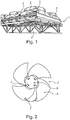
- an air heat exchanger 1 condenses and cools liquids that circulate in finned tube bundles 2.
- the finned tube bundles 2 are installed on an air heat exchanger 1. structure and they are blown by one or more fans 3 actuated by electric motors 4.
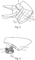
- the figure 2 illustrates an industrial fan 3 for air cooler according to the state of the art.
- This fan 3 comprises a disk-shaped hub 5 and a plurality of blades 6 radially connected to the disc of the hub 5 by means of a stud 7 provided on one end of each blade 6 and a flange (not shown schematically). provided on a face of the disc of the hub 5 and in which is inserted the stud 7 of the blade 6 with a blade angle to produce an axial air flow.
- the arrow F indicates the direction of rotation of the blades 6.
- the blades 6 have a curvature of the leading and trailing edges, in particular the leading edges have an angle of deflection before the ends of the blades relative to the radial direction.
- Free spaces are visible between the hub 5 and the base of the blades 6. These spaces induce a recirculation of the air flow at the base of the blade 6 from the intrados to the extrados. This recirculation of air contributes to a decrease in the pressure on the blade 6 and a decrease in the speed of the air in the zone at the base of the blade 6. Without means of joining between the hub 5 and the base of the blades 6 blades, about one third of the surface of the blade 6 can not be loaded with air and is rendered useless. As the air velocity profile is not homogeneous, the overall efficiency of the fan 3 is reduced.
- the figure 3 is a perspective view of a fan according to the invention, having a finned joining means 8 arranged at the base of the blades 6 to block the recirculation of air between the intrados and the extrados at the foot of the blade. On each blade, the fin extends along the pressure and the extrados perpendicularly to the surface of the blade 6 at the foot of the blade 6.
- the joining means 8 has a form of revolution.
- the joining means can be combined with sealing elements such as elastomer or silicone gaskets.
- the fan 1 comprises in the case of example a disk-shaped flat hub 5 bearing on its lower surface in the direction of the air four blades 6.
- the blades 6 extend radially between a blade base at the hub 5 and a blade head. They have a simplified form. Indeed each blade has a leading edge opposite a trailing edge which are both straight. The centroids of all sections along the blade 6 are perfectly aligned. Due to their simplified form, the manufacturing costs of the blades 6 are reduced.
- the fans 3 according to the invention comprise at least three blades 6.
- the length l of the blade 6 is divided by dotted lines into three zones, in particular an area at 30% of the length of the blade from the blade root, an area at 30% of the length of the blade from the blade head, and an area in the middle of the blade's rope. On each of these zones and at different points, pressure measurements between the intrados and extrados are carried out.
- each of the blades 6 has an aerodynamic profile such as the pressure difference ( ⁇ P1) between intrados and extrados is between 65% and 75% over an area at 30% of the blade length from the blade root with respect to the pressure difference ( ⁇ PC) between intrados and extrados in the middle of blade rope and such that the pressure difference ( ⁇ P2) between the lower and upper surfaces is between 125% and 135% over an area at 30% of the blade length from the blade head with respect to the difference in pressure ( ⁇ PC) between intrados and extrados in mid-rope of blade.
- ⁇ P1 pressure difference between intrados and extrados
- ⁇ PC pressure difference between intrados and extrados in the middle of blade rope
- each blade 6 has an aerodynamic profile as visible on the Figure 3 with a greater wedging angle at the blade root than at the blade tip, which makes it possible to have a more uniform pressure along the rope of the blade 6.
- the figure 4 illustrates the connection between the hub 5 and a blade 6.
- a stud 7 extends from the base of the blades and is fixed on a transverse wall 9 closing the blade root. This stud 7 makes it possible to attach the blades 6 on the underside of the disc of the hub 5 by means of a flange 10 fixed to the hub 5.
- this flange 10 comprises at least one jaw.
- this flange 10 comprises two jaws 10a, 10b fixed on the underside of the hub 5. As visible on the Figure 4 , the stud 7 of a blade 6 is housed in the two jaws 10a, 10b.
- the wedging of the blade angle is adjustable between 25 ° and 45 °.
- the angle of calibration is optimum calculated is about 36 °. It can be adjusted using an inclinometer. This inclinometer can be disposed on a perfectly flat area of the intrados surface of the blade. The pitch between the inclination angles of the blades 6 can thus be adjusted with an accuracy of + or - 0.1 °.
- the fan can be supplied in parts and assembled on site. It is no longer necessary to manufacture a fan in one piece, for example by molding a hub 5 with the blades 6, which can be bulky to carry and also not adjustable on site. Often the adjustment of the angle of setting is necessary in order to be able to adjust the air flow on site or to increase the performance of the heat exchanger in the future.
- the envelope of the blades can be made of composite materials, in the form of a premodelable fabric with a fiber reinforcement.
- This fiber reinforcement can be glass fabric.
- this envelope is impregnated with a two-component material with hardening such as polyester, vinyl esters, epoxides or the like. It is also possible that the coating is injection molded.
- the blades 6 can be hollow. They can be stiffened by filling the cavity with a light material such as a polyurethane foam. Due to their lightened structure, the blades are easier to install.
- a fan according to the invention at least 4 meters in diameter was produced and tested. This fan has been shown to have better performance and noise reduction than a "Super Low Noise” fan. In addition, due to the high aerodynamic efficiency of the fan according to the invention, a low operating speed is necessary and thus the production of noise remains limited.
- the fan according to the invention provides even better performance while emitting as much sound as a device of the prior art. It has been shown that such a fan also has better performance while consuming less power than a fan of the prior art.
- the invention extends to an air heat exchanger 1 with finned tubes 2 comprising a fan 3 according to the invention.
Landscapes
- Engineering & Computer Science (AREA)
- Mechanical Engineering (AREA)
- General Engineering & Computer Science (AREA)
- Physics & Mathematics (AREA)
- Thermal Sciences (AREA)
- Structures Of Non-Positive Displacement Pumps (AREA)
Priority Applications (1)
| Application Number | Priority Date | Filing Date | Title |
|---|---|---|---|
| PL15183722T PL3009684T3 (pl) | 2014-09-11 | 2015-09-03 | Wentylator do chłodnicy powietrznej |
Applications Claiming Priority (1)
| Application Number | Priority Date | Filing Date | Title |
|---|---|---|---|
| FR1458534A FR3025748B1 (fr) | 2014-09-11 | 2014-09-11 | Ventilateur pour aerorefrigerant. |
Publications (2)
| Publication Number | Publication Date |
|---|---|
| EP3009684A1 EP3009684A1 (fr) | 2016-04-20 |
| EP3009684B1 true EP3009684B1 (fr) | 2017-06-28 |
Family
ID=51987328
Family Applications (1)
| Application Number | Title | Priority Date | Filing Date |
|---|---|---|---|
| EP15183722.6A Active EP3009684B1 (fr) | 2014-09-11 | 2015-09-03 | Ventilateur pour aéroréfrigérant |
Country Status (6)
| Country | Link |
|---|---|
| US (1) | US20160076546A1 (pl) |
| EP (1) | EP3009684B1 (pl) |
| BR (1) | BR102015021916A2 (pl) |
| ES (1) | ES2644810T3 (pl) |
| FR (1) | FR3025748B1 (pl) |
| PL (1) | PL3009684T3 (pl) |
Families Citing this family (3)
| Publication number | Priority date | Publication date | Assignee | Title |
|---|---|---|---|---|
| US9618002B1 (en) * | 2013-09-27 | 2017-04-11 | University Of South Florida | Mini notched turbine generator |
| JP6802270B2 (ja) * | 2015-10-07 | 2020-12-16 | ミネベアミツミ株式会社 | インペラ、及び、そのインペラを備えた軸流ファン |
| US11391286B2 (en) * | 2020-10-02 | 2022-07-19 | Therma-Stor LLC | Portable blower fan assembly |
Family Cites Families (10)
| Publication number | Priority date | Publication date | Assignee | Title |
|---|---|---|---|---|
| US2918977A (en) * | 1956-06-25 | 1959-12-29 | Koppers Co Inc | Blade assembly |
| US3647317A (en) * | 1970-03-19 | 1972-03-07 | Fluor Prod Co Inc | Fiberglass fan assembly |
| JPS5912197A (ja) * | 1982-07-12 | 1984-01-21 | Mitsubishi Heavy Ind Ltd | 送風機の翼等の共振回避方法 |
| US4971143A (en) * | 1989-05-22 | 1990-11-20 | Carrier Corporation | Fan stator assembly for heat exchanger |
| US5564901A (en) * | 1993-12-14 | 1996-10-15 | The Moore Company | Low noise fan |
| US6086330A (en) | 1998-12-21 | 2000-07-11 | Motorola, Inc. | Low-noise, high-performance fan |
| ITMI991321A1 (it) * | 1999-06-14 | 2000-12-14 | Fbm Hudson Italiana Spa | Pala svergolata per girante composta da due elementi congiunti |
| US6517315B2 (en) | 2001-05-29 | 2003-02-11 | Hewlett-Packard Company | Enhanced performance fan with the use of winglets |
| US8672649B2 (en) * | 2007-10-10 | 2014-03-18 | Delta T Corporation | Ceiling fan system with brushless motor |
| CN102947595B (zh) | 2010-04-05 | 2016-10-12 | 穆尔风扇有限责任公司 | 包括包含超低噪音风扇叶片的轴流风扇的商业空气冷却装置 |
-
2014
- 2014-09-11 FR FR1458534A patent/FR3025748B1/fr active Active
-
2015
- 2015-09-03 PL PL15183722T patent/PL3009684T3/pl unknown
- 2015-09-03 EP EP15183722.6A patent/EP3009684B1/fr active Active
- 2015-09-03 ES ES15183722.6T patent/ES2644810T3/es active Active
- 2015-09-08 BR BR102015021916A patent/BR102015021916A2/pt active Search and Examination
- 2015-09-10 US US14/850,777 patent/US20160076546A1/en not_active Abandoned
Non-Patent Citations (1)
| Title |
|---|
| None * |
Also Published As
| Publication number | Publication date |
|---|---|
| US20160076546A1 (en) | 2016-03-17 |
| ES2644810T3 (es) | 2017-11-30 |
| FR3025748A1 (fr) | 2016-03-18 |
| PL3009684T3 (pl) | 2017-12-29 |
| EP3009684A1 (fr) | 2016-04-20 |
| FR3025748B1 (fr) | 2016-11-18 |
| BR102015021916A2 (pt) | 2016-07-19 |
Similar Documents
| Publication | Publication Date | Title |
|---|---|---|
| CA2862280C (fr) | Aube pour soufflante de turboreacteur | |
| EP3009684B1 (fr) | Ventilateur pour aéroréfrigérant | |
| EP3064708B1 (fr) | Aube composite de compresseur de turbomachine axiale avec une feuille de renfort et turbomachine comprenant une telle aube | |
| FR2976017A1 (fr) | Forme de pale profilee pour compresseur | |
| EP3273003B1 (fr) | Caisson à aubes de redresseur de compresseur de turbomachine axiale | |
| EP2735707A1 (fr) | Redresseur de turbomachine axiale avec virole interne segmentée et compresseur associé | |
| EP2530298A1 (fr) | Hélice pour machine hydraulique, machine hydraulique équipée d'une telle hélice et méthode d'assemblage d'une telle hélice | |
| EP2873810A1 (fr) | Couvercle annulaire de délimitation d'enceinte de lubrification de turbomachine | |
| EP2886804B1 (fr) | Dispositif d'étanchéité pour un compresseur de turbomachine | |
| WO2012156640A1 (fr) | Procédé de soufflage dans un diffuseur de turbine à gaz et diffuseur correspondant | |
| FR2889261A1 (fr) | Dispositif eolien | |
| FR2982649A1 (fr) | Dispositif de recuperation d'energie a partir d'un fluide en mouvement | |
| WO2014202903A1 (fr) | Roue centrifuge | |
| DK2679803T3 (en) | Rotor blade for wind energy systems and with a thick profile rear edge | |
| FR3060065A1 (fr) | Ensemble de pieces de turbomachine avec une aube de soufflante a plateforme integree et turbomachine correspondante | |
| EP2854259B1 (fr) | Rotor de machine électrique avec au moins une ailette de création d'un flux d'air à l'intérieur de l'arbre et machine électrique comportant un tel rotor | |
| EP3265654B1 (fr) | Disque aubagé monobloc comportant un moyeu raccourci et une pièce de maintien | |
| EP2930308A1 (fr) | Carter à facettes de compresseur de turbomachine axiale | |
| EP2960523B1 (fr) | Bague de fixation pour roue de turbine d'unité de traitement d'air et unité de traitement d'air comprenant un tel élément de fixation | |
| FR3006011A1 (fr) | Procede de fabrication d'une partie tournante de machine hydraulique, partie tournante fabriquee selon ce procede, machine hydraulique et installation de conversion d'energie | |
| BE1026325B1 (fr) | Virole a profilage evolutif pour compresseur de turbomachine | |
| FR3103855A1 (fr) | Structure améliorée de bord d’attaque d’aube. | |
| FR3105995A1 (fr) | Turbine a flux transverse | |
| FR3079868A1 (fr) | Lechette d'etancheite entre rotor et stator et turbine ainsi equipee | |
| WO2016050304A1 (fr) | Ventilateur pour automobile á pales optimisées pour l'acoustique et l'aérodynamique |
Legal Events
| Date | Code | Title | Description |
|---|---|---|---|
| PUAI | Public reference made under article 153(3) epc to a published international application that has entered the european phase |
Free format text: ORIGINAL CODE: 0009012 |
|
| AK | Designated contracting states |
Kind code of ref document: A1 Designated state(s): AL AT BE BG CH CY CZ DE DK EE ES FI FR GB GR HR HU IE IS IT LI LT LU LV MC MK MT NL NO PL PT RO RS SE SI SK SM TR |
|
| AX | Request for extension of the european patent |
Extension state: BA ME |
|
| RAP1 | Party data changed (applicant data changed or rights of an application transferred) |
Owner name: KELVION THERMAL SOLUTIONS |
|
| 17P | Request for examination filed |
Effective date: 20161020 |
|
| RBV | Designated contracting states (corrected) |
Designated state(s): AL AT BE BG CH CY CZ DE DK EE ES FI FR GB GR HR HU IE IS IT LI LT LU LV MC MK MT NL NO PL PT RO RS SE SI SK SM TR |
|
| GRAP | Despatch of communication of intention to grant a patent |
Free format text: ORIGINAL CODE: EPIDOSNIGR1 |
|
| STAA | Information on the status of an ep patent application or granted ep patent |
Free format text: STATUS: GRANT OF PATENT IS INTENDED |
|
| INTG | Intention to grant announced |
Effective date: 20170308 |
|
| GRAS | Grant fee paid |
Free format text: ORIGINAL CODE: EPIDOSNIGR3 |
|
| GRAA | (expected) grant |
Free format text: ORIGINAL CODE: 0009210 |
|
| STAA | Information on the status of an ep patent application or granted ep patent |
Free format text: STATUS: THE PATENT HAS BEEN GRANTED |
|
| AK | Designated contracting states |
Kind code of ref document: B1 Designated state(s): AL AT BE BG CH CY CZ DE DK EE ES FI FR GB GR HR HU IE IS IT LI LT LU LV MC MK MT NL NO PL PT RO RS SE SI SK SM TR |
|
| REG | Reference to a national code |
Ref country code: GB Ref legal event code: FG4D Free format text: NOT ENGLISH |
|
| REG | Reference to a national code |
Ref country code: CH Ref legal event code: EP |
|
| REG | Reference to a national code |
Ref country code: AT Ref legal event code: REF Ref document number: 905120 Country of ref document: AT Kind code of ref document: T Effective date: 20170715 |
|
| REG | Reference to a national code |
Ref country code: IE Ref legal event code: FG4D Free format text: LANGUAGE OF EP DOCUMENT: FRENCH |
|
| REG | Reference to a national code |
Ref country code: DE Ref legal event code: R096 Ref document number: 602015003308 Country of ref document: DE |
|
| REG | Reference to a national code |
Ref country code: NL Ref legal event code: FP |
|
| PG25 | Lapsed in a contracting state [announced via postgrant information from national office to epo] |
Ref country code: NO Free format text: LAPSE BECAUSE OF FAILURE TO SUBMIT A TRANSLATION OF THE DESCRIPTION OR TO PAY THE FEE WITHIN THE PRESCRIBED TIME-LIMIT Effective date: 20170928 Ref country code: LT Free format text: LAPSE BECAUSE OF FAILURE TO SUBMIT A TRANSLATION OF THE DESCRIPTION OR TO PAY THE FEE WITHIN THE PRESCRIBED TIME-LIMIT Effective date: 20170628 Ref country code: HR Free format text: LAPSE BECAUSE OF FAILURE TO SUBMIT A TRANSLATION OF THE DESCRIPTION OR TO PAY THE FEE WITHIN THE PRESCRIBED TIME-LIMIT Effective date: 20170628 Ref country code: FI Free format text: LAPSE BECAUSE OF FAILURE TO SUBMIT A TRANSLATION OF THE DESCRIPTION OR TO PAY THE FEE WITHIN THE PRESCRIBED TIME-LIMIT Effective date: 20170628 Ref country code: GR Free format text: LAPSE BECAUSE OF FAILURE TO SUBMIT A TRANSLATION OF THE DESCRIPTION OR TO PAY THE FEE WITHIN THE PRESCRIBED TIME-LIMIT Effective date: 20170929 |
|
| REG | Reference to a national code |
Ref country code: LT Ref legal event code: MG4D |
|
| REG | Reference to a national code |
Ref country code: AT Ref legal event code: MK05 Ref document number: 905120 Country of ref document: AT Kind code of ref document: T Effective date: 20170628 |
|
| PG25 | Lapsed in a contracting state [announced via postgrant information from national office to epo] |
Ref country code: BG Free format text: LAPSE BECAUSE OF FAILURE TO SUBMIT A TRANSLATION OF THE DESCRIPTION OR TO PAY THE FEE WITHIN THE PRESCRIBED TIME-LIMIT Effective date: 20170928 Ref country code: LV Free format text: LAPSE BECAUSE OF FAILURE TO SUBMIT A TRANSLATION OF THE DESCRIPTION OR TO PAY THE FEE WITHIN THE PRESCRIBED TIME-LIMIT Effective date: 20170628 Ref country code: RS Free format text: LAPSE BECAUSE OF FAILURE TO SUBMIT A TRANSLATION OF THE DESCRIPTION OR TO PAY THE FEE WITHIN THE PRESCRIBED TIME-LIMIT Effective date: 20170628 Ref country code: SE Free format text: LAPSE BECAUSE OF FAILURE TO SUBMIT A TRANSLATION OF THE DESCRIPTION OR TO PAY THE FEE WITHIN THE PRESCRIBED TIME-LIMIT Effective date: 20170628 |
|
| REG | Reference to a national code |
Ref country code: ES Ref legal event code: FG2A Ref document number: 2644810 Country of ref document: ES Kind code of ref document: T3 Effective date: 20171130 |
|
| PG25 | Lapsed in a contracting state [announced via postgrant information from national office to epo] |
Ref country code: AT Free format text: LAPSE BECAUSE OF FAILURE TO SUBMIT A TRANSLATION OF THE DESCRIPTION OR TO PAY THE FEE WITHIN THE PRESCRIBED TIME-LIMIT Effective date: 20170628 Ref country code: CZ Free format text: LAPSE BECAUSE OF FAILURE TO SUBMIT A TRANSLATION OF THE DESCRIPTION OR TO PAY THE FEE WITHIN THE PRESCRIBED TIME-LIMIT Effective date: 20170628 Ref country code: RO Free format text: LAPSE BECAUSE OF FAILURE TO SUBMIT A TRANSLATION OF THE DESCRIPTION OR TO PAY THE FEE WITHIN THE PRESCRIBED TIME-LIMIT Effective date: 20170628 Ref country code: EE Free format text: LAPSE BECAUSE OF FAILURE TO SUBMIT A TRANSLATION OF THE DESCRIPTION OR TO PAY THE FEE WITHIN THE PRESCRIBED TIME-LIMIT Effective date: 20170628 Ref country code: SK Free format text: LAPSE BECAUSE OF FAILURE TO SUBMIT A TRANSLATION OF THE DESCRIPTION OR TO PAY THE FEE WITHIN THE PRESCRIBED TIME-LIMIT Effective date: 20170628 |
|
| PG25 | Lapsed in a contracting state [announced via postgrant information from national office to epo] |
Ref country code: IS Free format text: LAPSE BECAUSE OF FAILURE TO SUBMIT A TRANSLATION OF THE DESCRIPTION OR TO PAY THE FEE WITHIN THE PRESCRIBED TIME-LIMIT Effective date: 20171028 Ref country code: SM Free format text: LAPSE BECAUSE OF FAILURE TO SUBMIT A TRANSLATION OF THE DESCRIPTION OR TO PAY THE FEE WITHIN THE PRESCRIBED TIME-LIMIT Effective date: 20170628 |
|
| REG | Reference to a national code |
Ref country code: DE Ref legal event code: R097 Ref document number: 602015003308 Country of ref document: DE |
|
| PG25 | Lapsed in a contracting state [announced via postgrant information from national office to epo] |
Ref country code: DK Free format text: LAPSE BECAUSE OF FAILURE TO SUBMIT A TRANSLATION OF THE DESCRIPTION OR TO PAY THE FEE WITHIN THE PRESCRIBED TIME-LIMIT Effective date: 20170628 |
|
| PLBE | No opposition filed within time limit |
Free format text: ORIGINAL CODE: 0009261 |
|
| STAA | Information on the status of an ep patent application or granted ep patent |
Free format text: STATUS: NO OPPOSITION FILED WITHIN TIME LIMIT |
|
| PG25 | Lapsed in a contracting state [announced via postgrant information from national office to epo] |
Ref country code: MC Free format text: LAPSE BECAUSE OF FAILURE TO SUBMIT A TRANSLATION OF THE DESCRIPTION OR TO PAY THE FEE WITHIN THE PRESCRIBED TIME-LIMIT Effective date: 20170628 |
|
| 26N | No opposition filed |
Effective date: 20180329 |
|
| REG | Reference to a national code |
Ref country code: IE Ref legal event code: MM4A |
|
| REG | Reference to a national code |
Ref country code: BE Ref legal event code: MM Effective date: 20170930 |
|
| PG25 | Lapsed in a contracting state [announced via postgrant information from national office to epo] |
Ref country code: LU Free format text: LAPSE BECAUSE OF NON-PAYMENT OF DUE FEES Effective date: 20170903 |
|
| REG | Reference to a national code |
Ref country code: FR Ref legal event code: ST Effective date: 20180531 |
|
| PG25 | Lapsed in a contracting state [announced via postgrant information from national office to epo] |
Ref country code: IE Free format text: LAPSE BECAUSE OF NON-PAYMENT OF DUE FEES Effective date: 20170903 |
|
| PG25 | Lapsed in a contracting state [announced via postgrant information from national office to epo] |
Ref country code: FR Free format text: LAPSE BECAUSE OF NON-PAYMENT OF DUE FEES Effective date: 20171002 Ref country code: SI Free format text: LAPSE BECAUSE OF FAILURE TO SUBMIT A TRANSLATION OF THE DESCRIPTION OR TO PAY THE FEE WITHIN THE PRESCRIBED TIME-LIMIT Effective date: 20170628 Ref country code: BE Free format text: LAPSE BECAUSE OF NON-PAYMENT OF DUE FEES Effective date: 20170930 |
|
| PG25 | Lapsed in a contracting state [announced via postgrant information from national office to epo] |
Ref country code: MT Free format text: LAPSE BECAUSE OF FAILURE TO SUBMIT A TRANSLATION OF THE DESCRIPTION OR TO PAY THE FEE WITHIN THE PRESCRIBED TIME-LIMIT Effective date: 20170628 |
|
| REG | Reference to a national code |
Ref country code: CH Ref legal event code: PL |
|
| PG25 | Lapsed in a contracting state [announced via postgrant information from national office to epo] |
Ref country code: HU Free format text: LAPSE BECAUSE OF FAILURE TO SUBMIT A TRANSLATION OF THE DESCRIPTION OR TO PAY THE FEE WITHIN THE PRESCRIBED TIME-LIMIT; INVALID AB INITIO Effective date: 20150903 |
|
| PG25 | Lapsed in a contracting state [announced via postgrant information from national office to epo] |
Ref country code: LI Free format text: LAPSE BECAUSE OF NON-PAYMENT OF DUE FEES Effective date: 20180930 Ref country code: CH Free format text: LAPSE BECAUSE OF NON-PAYMENT OF DUE FEES Effective date: 20180930 |
|
| PG25 | Lapsed in a contracting state [announced via postgrant information from national office to epo] |
Ref country code: CY Free format text: LAPSE BECAUSE OF FAILURE TO SUBMIT A TRANSLATION OF THE DESCRIPTION OR TO PAY THE FEE WITHIN THE PRESCRIBED TIME-LIMIT Effective date: 20170628 |
|
| PG25 | Lapsed in a contracting state [announced via postgrant information from national office to epo] |
Ref country code: MK Free format text: LAPSE BECAUSE OF FAILURE TO SUBMIT A TRANSLATION OF THE DESCRIPTION OR TO PAY THE FEE WITHIN THE PRESCRIBED TIME-LIMIT Effective date: 20170628 |
|
| PG25 | Lapsed in a contracting state [announced via postgrant information from national office to epo] |
Ref country code: TR Free format text: LAPSE BECAUSE OF FAILURE TO SUBMIT A TRANSLATION OF THE DESCRIPTION OR TO PAY THE FEE WITHIN THE PRESCRIBED TIME-LIMIT Effective date: 20170628 |
|
| PG25 | Lapsed in a contracting state [announced via postgrant information from national office to epo] |
Ref country code: PT Free format text: LAPSE BECAUSE OF FAILURE TO SUBMIT A TRANSLATION OF THE DESCRIPTION OR TO PAY THE FEE WITHIN THE PRESCRIBED TIME-LIMIT Effective date: 20170628 |
|
| PG25 | Lapsed in a contracting state [announced via postgrant information from national office to epo] |
Ref country code: AL Free format text: LAPSE BECAUSE OF FAILURE TO SUBMIT A TRANSLATION OF THE DESCRIPTION OR TO PAY THE FEE WITHIN THE PRESCRIBED TIME-LIMIT Effective date: 20170628 |
|
| GBPC | Gb: european patent ceased through non-payment of renewal fee |
Effective date: 20190903 |
|
| PG25 | Lapsed in a contracting state [announced via postgrant information from national office to epo] |
Ref country code: GB Free format text: LAPSE BECAUSE OF NON-PAYMENT OF DUE FEES Effective date: 20190903 |
|
| PGFP | Annual fee paid to national office [announced via postgrant information from national office to epo] |
Ref country code: DE Payment date: 20250919 Year of fee payment: 11 |
|
| PGFP | Annual fee paid to national office [announced via postgrant information from national office to epo] |
Ref country code: PL Payment date: 20250821 Year of fee payment: 11 Ref country code: NL Payment date: 20250918 Year of fee payment: 11 Ref country code: IT Payment date: 20250923 Year of fee payment: 11 |
|
| PGFP | Annual fee paid to national office [announced via postgrant information from national office to epo] |
Ref country code: ES Payment date: 20251028 Year of fee payment: 11 |