EP3009165A1 - Sonde electrique implantable - Google Patents
Sonde electrique implantable Download PDFInfo
- Publication number
- EP3009165A1 EP3009165A1 EP15184816.5A EP15184816A EP3009165A1 EP 3009165 A1 EP3009165 A1 EP 3009165A1 EP 15184816 A EP15184816 A EP 15184816A EP 3009165 A1 EP3009165 A1 EP 3009165A1
- Authority
- EP
- European Patent Office
- Prior art keywords
- electrical
- filter
- electrode
- lead
- implantable
- Prior art date
- Legal status (The legal status is an assumption and is not a legal conclusion. Google has not performed a legal analysis and makes no representation as to the accuracy of the status listed.)
- Withdrawn
Links
Images


Classifications
-
- A—HUMAN NECESSITIES
- A61—MEDICAL OR VETERINARY SCIENCE; HYGIENE
- A61N—ELECTROTHERAPY; MAGNETOTHERAPY; RADIATION THERAPY; ULTRASOUND THERAPY
- A61N1/00—Electrotherapy; Circuits therefor
- A61N1/02—Details
- A61N1/04—Electrodes
- A61N1/05—Electrodes for implantation or insertion into the body, e.g. heart electrode
- A61N1/056—Transvascular endocardial electrode systems
-
- A—HUMAN NECESSITIES
- A61—MEDICAL OR VETERINARY SCIENCE; HYGIENE
- A61N—ELECTROTHERAPY; MAGNETOTHERAPY; RADIATION THERAPY; ULTRASOUND THERAPY
- A61N1/00—Electrotherapy; Circuits therefor
- A61N1/02—Details
- A61N1/08—Arrangements or circuits for monitoring, protecting, controlling or indicating
- A61N1/086—Magnetic resonance imaging [MRI] compatible leads
Definitions
- the invention relates to a permanently or temporarily implantable device with an elongated electrical conductor, namely an implantable electrical line with an electrical filter to prevent radiofrequency-induced heating.
- Such devices such as electrode lines for electrostimulation, have the disadvantage that their electrical conductor can heat up in a magnetic resonance tomograph, because the magnetic fields prevailing in the magnetic resonance tomographs induce not inconsiderable electrical currents in the electrical conductor. Therefore, cardiac pacemaker patients today can usually not be examined or only to a limited extent in a magnetic resonance tomograph.
- implantable cardiac pacemakers or defibrillators typically have at least one pacing lead connected to their proximal end for connection to the pacemaker or defibrillator with a standard electrical connection and one or more electrode poles at their distal end provided for placement in the heart.
- Such an electrode pole serves to deliver electrical impulses to the tissue (myocardium) of the heart or to sense electric fields in order to be able to sense an activity of a heart within the scope of so-called sensing.
- electrode poles typically form electrically conductive surface portions of an electrode lead.
- Electrode poles are typically provided as a ring electrode in the form of a ring around the electrode lead or in the form of a tip or tip electrode at the distal end of the electrode lead.
- the electrode poles are electrically conductively connected via one or more electrical conductors to contacts of the electrical connection of the electrode line at its proximal end.
- the electrode leads run between the contacts of the electrical Connecting the electrode leads at the proximal end thereof and the electrode poles at the distal end of the electrode lead one or more electrical conductors electrically connecting one or more of the electrode poles to one or more of the contacts.
- These electrical conductors can be used, on the one hand, to transmit stimulation pulses to the electrode poles and, on the other hand, to transmit electrical signals picked up by the electrode poles to the proximal end of the electrode lead and are also referred to as function leads in the course of the further description.
- Such function lines are required for the functions of the respective electrode line electrical conductors and as such the risk that in them by external alternating magnetic fields electrical currents are induced, which can lead, for example, to an undesirable heating of the function lines or connected to her electrode poles or the delivery corresponding currents can lead to the surrounding tissue via the electrode poles and thus to a heating of the surrounding tissue.
- Implantable leads such as those u.a. used as electrode lines for cardiac pacemakers, act upon irradiation of electromagnetic waves similar to an antenna and can convert the absorbed energy into heat.
- the heating preferably occurs at lead ends, which can lead to tissue damage.
- a band stop filter or other electrical filter which is connected electrically in series, mechanically proximally or distally to the electrode pole, electrical waves in the radio frequency range are reflected and thus the heating of the tissue at the electrode pole is reduced.
- multi-pole electrode lines having a plurality of electrode poles, which are each connected with its own functional conductor with corresponding contacts of the electrical connection of the electrode line is also a line construction known, which is referred to as coradial.
- the individual functional conductors are insulated from one another to form a multi-start helix, in which the individual conductors form congruent helices with the same diameter and the same pitch, which mesh with each other in such a way that the turns of the individual helices, such as threads of a multi-start screw in the longitudinal direction of the helix, periodically follow one another and thus form a coradial conduction coil.
- coradial electrode lines ie electrode lines with coradial conduction coil
- the invention has for its object to provide an improved implantable lead with an electrical filter.
- an implantable electrical line with at least one helically coiled electrical conductor, an electrically conductive sheath electrically connected to the electrical conductor and an electrical filter, wherein the electrical filter seen in the longitudinal direction of the electrical line between a proximal and a distal longitudinal section a helix formed by the helically coiled electrical conductor and in the radial direction of the electrical line is arranged within the electrically conductive shell.
- the implantable electrical lead is a multi-pole electrode lead having a plurality of electrically conductive sheaths as electrode poles, which are each electrically connected to an electrical conductor, wherein the electrical conductors form a coradial conduction coil.
- the invention includes the realization that one of the most effective measures against MRI heating is a band-stop filter, an element that must be electrically connected between the lead and the associated electrode pole. However, there is no space (especially radially) for a coradial electrode lead in order to accommodate such a filter mechanically directly proximal to the respective electrode pole. In addition, one filter may be needed for each of the up to 4 electrode poles. According to the invention, the respective electrical filters are therefore housed axially displaced at locations, which offer more space without compromising the flexibility or other functional properties of the electrode. As an alternative to a band stop filter, another electrical filter, for example a low-pass filter, can be used.
- a respective electrical filter for the middle and / or or the most distal electrode pole within the electrically conductive shell, which forms the respectively adjacent, respectively next-proximal electrode pole is arranged. That a respective electrical filter for a respective electrode pole is at least in the case of a middle Elektrodenpols not within the associated electrically conductive shell but within a nearest, adjacent electrically conductive shell arranged. This facilitates contacting a filter for an electrode pole and the associated electrically conductive sheath.
- the electrical filter for the most proximal electrode pole is disposed proximal to the associated electrically conducting sheath, preferably in a region of the electrode lead which may be stiffer and / or of larger diameter than the distal region without affecting the other functions of the electrode lead.
- the electrical filter for the most distal electrode pole is distal to this electrode pole, e.g. in a flexible tip region of the electrode line, arranged.
- a respective electrically conductive shell preferably forms in each case a ring electrode of the electrode line.
- the electrical filter is a band stop or low pass filter.
- a respective electrical filter with disconnected line ends of a split conductor of a Coradialplanetarylzu ein electrically connected and other conductors the Coradialplanetarylzu effet are not separated in the region of the electric filter, but passed continuously past the electric filter.
- a placement of a most distal electrical filter in the distal end of the electrode line is advisable, because a flexible, distal end without electrode poles is needed in any case to avoid phrenic nerve stimulation, which may otherwise occur at too distal position of the ring electrodes.
- the implantable cardiac stimulator 10 may be a pacemaker or a cardioverter / defibrillator (ICD).
- the heart stimulator 10 is a ventricular pacemaker and defibrillator.
- Other known cardiac stimulators are dual chamber pacemakers for stimulation of the right atrium and right ventricle, or biventricular pacemakers, which can also stimulate the left ventricle in addition to the right ventricle.
- Such stimulators typically have a housing 12, which is usually made of metal and thus is electrically conductive and can serve as a large electrode pole.
- a terminal housing 14 is typically attached, which is also referred to as a header.
- Such a header typically has contact sockets for receiving plug contacts.
- the contact sockets have electrical contacts 16, which are connected via corresponding conductors with an arranged in the housing 12 of the heart stimulator 10 electronics.
- the electrode lead 20 also constitutes an implantable medical device in general and an implantable electrical lead in particular.
- electrode poles are in a manner known per se in the form of a tip or tip electrode 22 and in the vicinity thereof arranged ring electrode 24 is arranged.
- the electrode poles 22 and 24 are designed such that, depending on the function of a cardiac stimulator to which the electrode lead 20 is connected, they serve to sense electrical potentials of the heart tissue (myocardium) or to emit electrical signals, for example to deliver stimulation pulses to the surrounding them Heart tissue, are formed.
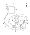
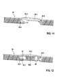
- Fig. 1 shows how the electrode poles, so the tip electrode 22 and the ring electrode 24, in the application, the electrode line 20, located in the apex of a right ventricle of a heart.
- Both the tip electrode 22 and the ring electrode 24 are electrically connected via a respective electrical conductor 26.1 or 26.2 with a plug contact 28 at the proximal end of the electrode line 20.
- the electrical conductors together form a Coradialplanetarylzutechnisch 26.
- the plug contact 28 has electrical contacts which correspond to the electrical contacts 16 of the contact socket in the connection housing 14 of the implantable heart stimulator.
- the electrical conductors 26 in the electrode line 20 may be formed as approximately elongated cable conductor or as a helical coiled conductor.
- Such conductors electrically conductively connect functional electrode poles to electrical contacts of the plug-in contact at the proximal end of the electrode line 20 are referred to as function conductors in the context of this text, since they transmit, for example, electrical signals from the plug contact to the respective electrode pole, or sensed signals representing electrical potential from the sensor lead respective electrode pole to the plug contact and thus serve the elementary function of the medical device.
- the electrical conductors 26, which connect the electrode poles 22 and 24, respectively, to the electrical contacts of the plug 28 of the electrode line 20, are surrounded over most of their length by an insulating sheath, so that an electrical contact to the tissue of the heart is targeted via the electrode poles comes about.
- the electrode line 20 In addition to the electrode poles 22 and 24, which typically serve the (in this case, ventricular) stimulation of the heart tissue, the electrode line 20 also has two larger-area electrode poles 30 and 32, which serve as defibrillation electrodes and are formed by at least one bare helix-like coiled wire ,
- an ablation electrode lead can in principle also be used, which likewise projects into the heart of a patient in the application and which is controlled by a device arranged outside the patient and is connected to it for this purpose.
- Fig. 1 shows an electrode line 20 with two electrode poles 22 and 24, of which the electrode pole 24 is a ring electrode. Notwithstanding the deviation example in Fig. 1
- the present invention also relates to electrode lines having a plurality of electrode poles in the form of ring electrodes.
- each electrode pole is preferably associated with an electrical filter 40, which is preferably a bandstop or low-pass filter.
- the FIGS. 2 to 14 show by means of examples, such as in particular with coradial electrode lines such electrical filter 40 can be arranged and electrically connected to a respective Elektrodenpol.
- an electrical filter includes a metallic wire or foil that is wound so that a resulting inductance and (parasitic) capacitance form a band stop or low pass filter whose resonant or notch frequency is close to the frequency of one expected interfering electromagnetic field, in particular at the frequency of such electric fields, as they are generated by a magnetic resonance tomograph (MRI) device.
- MRI magnetic resonance tomograph
- the electric filter 40 comprises a coil of single-sided metallized foil spirally wound about a hollow cylindrical core, an additional capacitive element may be electrically connected in parallel to the inductance if the parasitic capacitance is insufficient by the capacitance formed by the metallized foil. to achieve a desired resonance frequency.
- All variants of the electric filter have a central lumen through which a stylet or guide wire can be pushed.
- a respective electrical filter must be installed in an electrode body of the electrode line so that the electrical filter is protected against additional load, for example against cyclic bending.
- a respective electric filter 40 under an example, a ring electrode 24 forming electrical to arrange conductive sheath.
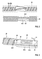
- a Coradialplanetarylzutechnisch 26 in a place where an electric filter 40 is to be mounted, are turned on so that initially the helical shape of the Coradialplanetarylzu effet is interrupted at this location, without the electrical conductors themselves are severed (see Fig. 2 ).
- Fig. 2 is a Coradialplanetarylzutechnisch to see in which two double lines - one light and one dark - are connected to a Coradialplanetaryl.
- this Coradialplanetarylzu liber contact the two dark conductors 26a a first Elektrodenpol and the two bright conductors 26b a second Elektrodenpol.
- One of the two electrode poles 24 is in the finished state of the electrode line to the in Fig. 2 shown location where the helical shape of the Coradialplanetarylzu effet is interrupted.
- Fig. 2 does not show an image of the finished electrode line 20.
- Fig. 3 shows how after turning the Coradialplanetarylzu effet an electric filter 40 can be arranged in the turned-up portion of the Coradialplanetarylzu effet.
- one of the conductors 26 (which is in FIG Fig. 3 dark) is interrupted and a stripped end of this conductor connected to a proximal terminal shell 42 of the electric filter 40, for example by welding.
- a second terminal sheath 46 at the other end of the electric filter 40 with an electrically conductive sheath forming an electrode pole in the Fig. 3 not shown.
- electrical shell is then over the in Fig. 3 pushed electrical filter 40 and electrically connected to the wire 44.
- the electrical filter 40 is located within that electrically conductive shell which forms the electrode pole to which the electrical filter 40 is assigned.
- an auxiliary body 48 for example, a plastic tube (for example, polyimide) into the central lumen of the coradial coil and the electric filter 40 so as to hold the electric filter 40 in place, and so on long to stabilize until the electrode line 20 is completed.
- the plastic tube 48 can then remain in place or be removed.
- a respective electrically conductive filter 40 can also be housed within an adjacent electrically conductive sheath, not under that electrically conductive sheath , which forms the electrode pole to which the electrical filter 40 is associated.
- the respective electrical filter 40 must be electrically connected to that of the conductors 26 which leads to an adjacent electrically conductive sheath and not to that electrically conductive sheath within which the electrical filter 40 is disposed. The preparation of such an electrode line is in the FIGS. 7 to 14 described in more detail.
- a respective electrical filter 40 for a proximal electrode pole can also be arranged proximally of this electrode pole, since in this region an electrode lead can typically also be arranged as alternative stiffening support elements for stabilizing the filter.
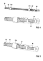
- a corresponding conductor 26 is used an electrode line could contact the electrical shell of the distal ring electrode pole directly, continued a few millimeters and contacted with a (proximal) terminal sheath 42 of the corresponding electrical filter 40.
- the corresponding distal terminal sheath 46 of the electrical filter 40 is finally connected to the electrically conductive sheath via a wire 44 'returned to the electrical sheath, for example via a loosely wound cable; please refer Fig. 4 ,
- the electrical filter 40 has a wire 52 which is wound in one layer and a coil thus forms an inductance of the electric filter 40. If the wire forming the coil and thus the inductance of the electric filter is not wound in one layer (or with an odd number of layers), but with an even number of layers, both terminal sheaths of the electrical filter may be provided at its proximal end, for example in particular, the wire 44 'only has to be returned over a shorter distance; please refer Fig. 5 ,
- an electrical filter for the then distal electrode pole can be arranged as in the FIGS. 4 or 5 is shown.
- the electrical filter for the proximal electrode pole can be placed proximally thereof, as previously mentioned. In this case, no electrical filter is disposed within an electrically conductive shell.
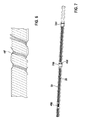
- individual conductors may be unscrewed from the Coradialplanetarylzu Arthur and freed from their isolation if necessary.
- winding gaps occur in the remaining coradial spiral feed line.
- an insulating layer for example a silicone tube, and then the non-insulated conductors are wound into the winding gaps be like this in Fig. 6 is shown.
- An additional support hose (for example, made of polyimide) can be mounted inside the Coradialplanetarylzutechnische.
- An additional support hose (for example, made of polyimide) can be mounted inside the Coradialplanetarylzu admir.
- FIGS. 7 to 14 illustrate how an electrode lead according to an advantageous embodiment can be made, wherein a respective electrical filter is disposed within an electrically conductive sheath adjacent to the electrically conductive sheath forming the electrode pole to which the electrical filter is associated and in which electrical filter for the most proximal Elektrodenpol proximal thereof is arranged.
- Fig. 7 shows a portion of the finished electrode line 20 from the outside.
- a proximal ring electrode pole 24p and a distal ring electrode pole 24d are formed by a respective electrically conductive shell, for example a metal shell.
- the electrode line 20 carries an electrically insulating sheath 50 between the electrode poles and on both sides of and beyond the electrode poles, which in the exemplary embodiment is formed by a silicone tube.
- a Coradialplanetarylzutechnisch 26 Within this shell 50 and within the electrically insulating sheaths 24p and 24d extends a Coradialplanetarylzutechnisch 26, in particular of four electrical conductors 26.1, 26.3, 26.3 and 26.4 (see also FIG. 8 ) is formed.
- the associated electric filter 40p is disposed.
- the electrical filter 40d for the distal electrode pole 24d is disposed within the electrically conductive sheath of the proximal electrode pole 24p.
- FIGS. 8 and 9 first explain the installation of the proximal electric filter 40p.
- the Coradialplanetarylzu Arthur 26 is where the proximal electrical filter 40p is to be arranged, turned up and the electrode 26.1 associated with the proximal Elektrodenpol electrical conductor 26.1 separated.
- the remaining electrical conductors 26.2, 26.3 and 26.4 are not separated and remain insulated.
- the split ends of the conductor 26.1 are freed from their isolation; please refer Fig. 8 ,
- the electric filter 40p may be inserted at the location vacated by the untwisting of the turns.
- a polyimide hose 48 is passed through the lumen of the coradial coil feed line 26 and the electric filter 40p to reliably and stably hold the electric filter 40p in place.
- the freed from the isolation free wire ends of the split conductor 26.1 are welded to the proximal terminal shell 42 and the distal terminal shell 46 of the electric filter 40p and electrically connected in this way; please refer Fig. 9 ,
- the electrically insulating sheath 50 is pushed in the form of a silicone tube over the assembly produced in this way.
- the coradial helix feed line 26 is turned on at the location of the proximal electrode pole 24p, and a further conductor 26.2 of the coradial helix feed line 26 is separated and the severed ends are freed of their insulation.
- a further conductor 26.2 of the coradial helix feed line 26 is separated and the severed ends are freed of their insulation.
- the distal electric filter 40d is now inserted into the space created by unscrewing the coradial coil 26, and its terminal sheaths 42 and 46 are electrically connected by welding to the disconnected and disconnected ends of the conductor 26.2; please refer Fig. 12 ,
- the electrically conductive sheath forming the proximal electrode pole 24p can be pushed onto the coradial coil feed line 26 directly via the electrical filter 40d; please refer Fig. 12 and 13 ,
- the free of insulation free end of the conductor 26.1 (the dark conductor) can be connected to the corresponding electrically conductive sheath 24p; please refer Fig. 12 ,
- That part of the conductor 26.1 (of the conductor shown dark in the figure), which extends distally of the proximal electrode pole 24p, is no longer electrically contacted and serves exclusively for the fact that no winding gaps are formed in the further coradial application lead 26.
Applications Claiming Priority (1)
| Application Number | Priority Date | Filing Date | Title |
|---|---|---|---|
| US201462064486P | 2014-10-16 | 2014-10-16 |
Publications (1)
| Publication Number | Publication Date |
|---|---|
| EP3009165A1 true EP3009165A1 (fr) | 2016-04-20 |
Family
ID=54106251
Family Applications (1)
| Application Number | Title | Priority Date | Filing Date |
|---|---|---|---|
| EP15184816.5A Withdrawn EP3009165A1 (fr) | 2014-10-16 | 2015-09-11 | Sonde electrique implantable |
Country Status (2)
| Country | Link |
|---|---|
| US (2) | US20160106973A1 (fr) |
| EP (1) | EP3009165A1 (fr) |
Citations (4)
| Publication number | Priority date | Publication date | Assignee | Title |
|---|---|---|---|---|
| US6421567B1 (en) * | 1999-06-25 | 2002-07-16 | Biotronik Mess-Und Therapiegeraete Gmbh & Co. Ingenieurbuero Berlin | Implantable lead with mechanical and electrical selectively operable electrodes |
| US20110015713A1 (en) * | 2008-10-23 | 2011-01-20 | Pacesetter, Inc. | Systems and methods for reducing lead heating and the risks of mri-induced stimulation |
| US20110034979A1 (en) * | 2009-08-07 | 2011-02-10 | Pacesetter, Inc. | Implantable medical device lead incorporating insulated coils formed as inductive bandstop filters to reduce lead heating during mri |
| WO2014164972A1 (fr) * | 2013-03-15 | 2014-10-09 | Imricor Medical Systems, Inc. | Poignée et gaine orientable compatibles irm |
Family Cites Families (4)
| Publication number | Priority date | Publication date | Assignee | Title |
|---|---|---|---|---|
| US9468750B2 (en) * | 2006-11-09 | 2016-10-18 | Greatbatch Ltd. | Multilayer planar spiral inductor filter for medical therapeutic or diagnostic applications |
| US20100331942A1 (en) * | 2009-06-29 | 2010-12-30 | Pacesetter, Inc. | Mri compatible implantable medical lead and method of making same |
| US20110125240A1 (en) * | 2009-11-20 | 2011-05-26 | Pacesetter, Inc. | Biocompatible inductor for implantable lead and method of making same |
| US20110152990A1 (en) * | 2009-12-22 | 2011-06-23 | Pacesetter, Inc. | Mri compatible lead employing multiple miniature inductors |
-
2015
- 2015-09-11 EP EP15184816.5A patent/EP3009165A1/fr not_active Withdrawn
- 2015-09-15 US US14/855,253 patent/US20160106973A1/en not_active Abandoned
-
2017
- 2017-08-07 US US15/670,766 patent/US10434304B2/en not_active Expired - Fee Related
Patent Citations (4)
| Publication number | Priority date | Publication date | Assignee | Title |
|---|---|---|---|---|
| US6421567B1 (en) * | 1999-06-25 | 2002-07-16 | Biotronik Mess-Und Therapiegeraete Gmbh & Co. Ingenieurbuero Berlin | Implantable lead with mechanical and electrical selectively operable electrodes |
| US20110015713A1 (en) * | 2008-10-23 | 2011-01-20 | Pacesetter, Inc. | Systems and methods for reducing lead heating and the risks of mri-induced stimulation |
| US20110034979A1 (en) * | 2009-08-07 | 2011-02-10 | Pacesetter, Inc. | Implantable medical device lead incorporating insulated coils formed as inductive bandstop filters to reduce lead heating during mri |
| WO2014164972A1 (fr) * | 2013-03-15 | 2014-10-09 | Imricor Medical Systems, Inc. | Poignée et gaine orientable compatibles irm |
Also Published As
| Publication number | Publication date |
|---|---|
| US20160106973A1 (en) | 2016-04-21 |
| US20170333697A1 (en) | 2017-11-23 |
| US10434304B2 (en) | 2019-10-08 |
Similar Documents
| Publication | Publication Date | Title |
|---|---|---|
| EP1923094B1 (fr) | Cathéter à électrode destiné à des interventions | |
| DE69820418T2 (de) | Spulendrahtisolierung für biomedizinische leiter | |
| EP2359898A2 (fr) | Élément implantable avec des moyens pour réduire une densité de flux | |
| DE112010001330T5 (de) | MRT-kompatible implantierbare Anschlusselektroden-Schnittstelle | |
| EP2465572B1 (fr) | Fil implantable compatible avec l'IRM | |
| EP2110154B1 (fr) | Dispositif de réduction de l'occurrence de pannes pour implants allongés | |
| EP2602000B1 (fr) | Ligne d'électrodes implantables | |
| EP2359895B1 (fr) | Sonde d'adaptation pour l'introduction d'implants médicaux actifs dans des dispositifs d'électrodes implantées et ensemble comprenant un dispositif d'électrodes implantables et une sonde d'adaptation | |
| EP2985053A1 (fr) | Ligne électrique implantable | |
| EP2465573B1 (fr) | Appareil implantable | |
| EP2548609A1 (fr) | Dérivation d'électrode multi-usage unipolaire et installation de stimulation et de défibrillation | |
| EP2478933A2 (fr) | Appareil implantable | |
| EP2465569B1 (fr) | Appareil implantable | |
| EP2359894A1 (fr) | Electrode dotée d'un filtre HF pour implants médicaux actifs | |
| EP2110156B1 (fr) | Elément de découplage de champs à utiliser avec une sonde implantable et appareil médical implantable | |
| EP2446922B1 (fr) | Conducteurs implantables avec des conducteurs supplémentaires pour le découplage de champs | |
| EP3009165A1 (fr) | Sonde electrique implantable | |
| EP2985054B1 (fr) | Appareil implantable doté d'un filtre électrique | |
| EP2468353A1 (fr) | Appareil implantable | |
| EP2848282B1 (fr) | Appareil implantable | |
| EP2853288B1 (fr) | Appareil implantable et procédé de fabrication d'un appareil implantable | |
| EP2465570B1 (fr) | Appareil implantable | |
| EP0306443B1 (fr) | Prise coaxiale pour stimulateur cardiaque | |
| EP2143463A1 (fr) | Mesures améliorées de perte de chemin dans des communications sans fil | |
| EP3025756B1 (fr) | Prolongement d'electrodes integre dans un implant actif |
Legal Events
| Date | Code | Title | Description |
|---|---|---|---|
| PUAI | Public reference made under article 153(3) epc to a published international application that has entered the european phase |
Free format text: ORIGINAL CODE: 0009012 |
|
| AK | Designated contracting states |
Kind code of ref document: A1 Designated state(s): AL AT BE BG CH CY CZ DE DK EE ES FI FR GB GR HR HU IE IS IT LI LT LU LV MC MK MT NL NO PL PT RO RS SE SI SK SM TR |
|
| AX | Request for extension of the european patent |
Extension state: BA ME |
|
| 17P | Request for examination filed |
Effective date: 20161011 |
|
| RBV | Designated contracting states (corrected) |
Designated state(s): AL AT BE BG CH CY CZ DE DK EE ES FI FR GB GR HR HU IE IS IT LI LT LU LV MC MK MT NL NO PL PT RO RS SE SI SK SM TR |
|
| STAA | Information on the status of an ep patent application or granted ep patent |
Free format text: STATUS: EXAMINATION IS IN PROGRESS |
|
| 17Q | First examination report despatched |
Effective date: 20190517 |
|
| STAA | Information on the status of an ep patent application or granted ep patent |
Free format text: STATUS: EXAMINATION IS IN PROGRESS |
|
| GRAP | Despatch of communication of intention to grant a patent |
Free format text: ORIGINAL CODE: EPIDOSNIGR1 |
|
| STAA | Information on the status of an ep patent application or granted ep patent |
Free format text: STATUS: GRANT OF PATENT IS INTENDED |
|
| RIC1 | Information provided on ipc code assigned before grant |
Ipc: A61N 1/05 20060101AFI20220210BHEP |
|
| INTG | Intention to grant announced |
Effective date: 20220303 |
|
| STAA | Information on the status of an ep patent application or granted ep patent |
Free format text: STATUS: THE APPLICATION IS DEEMED TO BE WITHDRAWN |
|
| 18D | Application deemed to be withdrawn |
Effective date: 20220714 |