EP3009054B1 - Air heating type cooking pan - Google Patents
Air heating type cooking pan Download PDFInfo
- Publication number
- EP3009054B1 EP3009054B1 EP14810884.8A EP14810884A EP3009054B1 EP 3009054 B1 EP3009054 B1 EP 3009054B1 EP 14810884 A EP14810884 A EP 14810884A EP 3009054 B1 EP3009054 B1 EP 3009054B1
- Authority
- EP
- European Patent Office
- Prior art keywords
- heating chamber
- hot air
- air
- type cooking
- disposed
- Prior art date
- Legal status (The legal status is an assumption and is not a legal conclusion. Google has not performed a legal analysis and makes no representation as to the accuracy of the status listed.)
- Active
Links
- 238000010438 heat treatment Methods 0.000 title claims description 96
- 238000010411 cooking Methods 0.000 title claims description 27
- 238000007664 blowing Methods 0.000 claims description 20
- 230000005540 biological transmission Effects 0.000 claims description 7
- 238000004064 recycling Methods 0.000 claims description 7
- 238000000034 method Methods 0.000 claims description 3
- 235000013305 food Nutrition 0.000 description 17
- 238000003756 stirring Methods 0.000 description 12
- UQMRAFJOBWOFNS-UHFFFAOYSA-N butyl 2-(2,4-dichlorophenoxy)acetate Chemical compound CCCCOC(=O)COC1=CC=C(Cl)C=C1Cl UQMRAFJOBWOFNS-UHFFFAOYSA-N 0.000 description 6
- 230000007547 defect Effects 0.000 description 2
- 230000003670 easy-to-clean Effects 0.000 description 2
- 230000009286 beneficial effect Effects 0.000 description 1
- 230000015556 catabolic process Effects 0.000 description 1
- 230000000694 effects Effects 0.000 description 1
- 238000005485 electric heating Methods 0.000 description 1
Images


Classifications
-
- A—HUMAN NECESSITIES
- A47—FURNITURE; DOMESTIC ARTICLES OR APPLIANCES; COFFEE MILLS; SPICE MILLS; SUCTION CLEANERS IN GENERAL
- A47J—KITCHEN EQUIPMENT; COFFEE MILLS; SPICE MILLS; APPARATUS FOR MAKING BEVERAGES
- A47J37/00—Baking; Roasting; Grilling; Frying
- A47J37/06—Roasters; Grills; Sandwich grills
- A47J37/0623—Small-size cooking ovens, i.e. defining an at least partially closed cooking cavity
- A47J37/0629—Small-size cooking ovens, i.e. defining an at least partially closed cooking cavity with electric heating elements
- A47J37/0641—Small-size cooking ovens, i.e. defining an at least partially closed cooking cavity with electric heating elements with forced air circulation, e.g. air fryers
Definitions
- the present invention relates to a technical field of electric heating cooking appliances, in particular, to an air heating type cooking pan.
- An existing air heating type cooking pan usually consists of a cover body, a pan body, a stirring paddle and a hot air generating device; the cover body is disposed on the pan body; the stirring paddle is disposed at the bottom in the pan body; one end of the stirring paddle is located in the center of the pan body, and is in connection with a motor in a transmission way; the hot air generating device is disposed on one side of the pan body and blows hot air to the space surrounded by the pan body and the cover body so as to heat the food in the pan body.
- the direction in which the hot air generating device blows air is fixed, so the interior of the pan body cannot be heated uniformly.
- a further air heating type cooking pan is known from CN-U-202051500 , which discloses an air heating type cooking pan according to the preamble of independent claim 1.
- the objective of the present invention is to provide an air heating type cooking pan which has a simple and reasonable structure, heats uniformly, is easy to clean and is low in cost, to overcome the defects in the prior art.
- An air heating type cooking pan consists of a machine body, a cover body and a pan body; the machine body is provided with a heating chamber and a hot air generating device which blows hot air into the heating chamber, wherein the air heating type cooking pan also consists of a turntable motor and at least three support roller wheels; the turntable motor is disposed in the machine body; a motor shaft of the turntable motor drives the pan body to rotate via a driving member; the support roller wheels are circumferentially distributed and located between the bottom of the pan body and the bottom of the heating chamber.
- the machine body consists of a bottom shell, a thermal insulating tray, an upper shell and a lateral plate; the thermal insulating tray and the upper shell are respectively disposed on the bottom shell; the top face of the thermal insulating tray is recessed downward to form the heating chamber with an opened top; the upper shell is located on one side of the opening of the heating chamber and is connected with the lateral plate; and the surface of the lateral plate is provided with a hot air outlet.
- the top of the lateral plate inclines toward the heating chamber.
- the driving member is a non-round rotary head; the non-round rotary head is located in the center of the bottom in the heating chamber; the bottom of the pan body is provided with a non-round groove corresponding to the non-round rotary head; the non-round rotary head and the non-round groove are matched in an inserting way; the turntable motor is located at the bottom out of the heating chamber; and the motor shaft penetrates the bottom of the heating chamber to be connected with the non-round rotary head.
- the support roller wheels are circumferentially distributed at an equal interval around the motor shaft; the support roller wheels are disposed on a wheel stand; and the wheel stand and the bottom of the heating chamber are fixed.
- the hot air generating device is disposed in the space surrounded by the bottom shell and the upper shell; the hot air generating device consists of a centrifuge wind wheel, a blowing motor, a fixed mount, a heating element and a thermal insulating fairing; the fixed mount is connected with the thermal insulating tray; one end of the blowing motor is connected with the outer side of the fixed mount, while the other end faces an air suction opening on the bottom shell; the centrifuge wind wheel is disposed on the inner side of the fixed mount and is in connection with the blowing motor in a transmission way; the heating element is disposed at the upper end of the fixed mount and close to the hot air outlet; the thermal insulating fairing is fixed at the upper end of the fixed mount and located on the outer side of the heating element; the thermal insulating fairing contains the heating element inside and together with fixed mount forms a hot air channel; and the port of the hot air channel corresponds to the hot air outlet.
- An air channel is formed between the bottom shell and the thermal insulating tray; the air channel communicates with the air suction opening of the centrifuge wind wheel; the surface of the heating chamber is provided with a hot air recycling hole; and the hot air recycling hole connects the heating chamber and the air channel.
- the rear end of the blowing motor is provided with radiating fins; and the radiating fins are in connection with the rotating shaft of the blowing motor in a transmission way.
- the surface of the lateral plate is also provided with a lamp body; the cover body is a transparent cover; and the top of the cover body is provided with a handle.
- a lamp body is also provided with a lamp body; the cover body is a transparent cover; and the top of the cover body is provided with a handle.
- the upper shell is internally provided with a timer and a microswitch; an adjusting shaft of the timer extends out of the upper shell and is connected with an adjusting knob; a button of the microswitch is connected with one end of a switching drive rod; the other end of the switching drive rod extends out of the lateral plate; in the process that the cover body is closed downward, the cover body triggers the switching drive rod, the microswitch is closed.
- the timer is used for controlling the working time of the machine.
- the microswitch can be connected to the power circuit so as to ensure that the machine stops working when the cover body is opened, thus preventing the hot air from directly blowing user. The use is safer.
- a bracket is also included.
- the bracket is disposed in the pan body, including a bracket mesh, a short-leg rack and a long-leg rack; the short-leg rack and the long-leg rack are respectively disposed on the upper and lower surfaces of the bracket mesh.
- the bracket can be turned for use, thus generating different bearing heights.
- the present invention has the following beneficial effects: When the air heating type cooking pan is in the heating process, the pan body rotates relative to the hot air outlet, so each part of the pan body has the opportunity to be directly blown by the hot air from the hot air outlet, thus achieving the purpose of uniform heating.
- the support roller wheels are disposed between the bottom of the pan body and the heating chamber, so that the pan body rotates more smoothly.
- the pan body has no stirring paddle inside, can be easily taken out from the machine body, and is convenient to clean.
- an air heating type cooking pan consists of a machine body 100, a cover body 20 and a pan body 9; the machine body 100 is provided with a heating chamber 51 and a hot air generating device 60 which blows hot air into the heating chamber 51; one side of the heating chamber 51 is open; the pan body 9 is placed in the heating chamber 51 from the opened side of the heating chamber 51, and the cover body 20 covers outer side the opening of the heating chamber 51.
- the air heating type cooking pan also consists of a rotary mechanism and at least three support roller wheels 4 (six support roller wheels 4 in this embodiment); the rotary mechanism is disposed in the machine body 100, driving the pan body 9 to rotate via a driving member.
- the rotary mechanism consists of a motor, for example a turntable motor 50, and the motor shaft 501 of the turntable motor 50 is directly connected to the pan body 9 and drives the pan body 9to rotate.
- a plurality of support roller wheels 4 are circumferentially distributed and located between the bottom of the pan body 9 and the heating chamber 51.
- the driving member can be a non-round rotary head 2, as shown in Figure 4 : a polygonal rotary head, the non-round rotary head 2 is located at the bottom in the heating chamber 51; the bottom of the pan body 9 is provided with a non-round groove 91 with a shape and a size corresponding to the non-round rotary head 2; the non-round rotary head 2 is matched with non-round groove 91 in an inserting way.
- the non-round rotary head 2 is disposed at the center of the bottom of the heating chamber 51, and the non-round groove 91 is disposed at the center of the bottom of the pan body.
- the turntable motor 50 is located on the outer side of the bottom of the heating chamber 51; the motor shaft 501 penetrates through the bottom of the heating chamber 51 and is connected with the non-round rotary head 2; during rotary working, the turntable motor 50 drives the non-round rotary head 2 to rotate, and the pan body 9 rotates in the heating chamber 51 by the effect of the match of the round rotary head 2 and the non-round groove 91 such that the hot air blown uniformly exchanges heat with the food in the pan body 9.
- the support roller wheels 4 are circumferentially distributed at an equal interval around the motor shaft 501; the support roller wheels 4 are disposed on the wheel stand 3, and the wheel stand 3 and the bottom of the heating chamber 51 are fixed. In this way, the rotary pan body 9 can smoothly move along the plurality of support roller wheels 4 at the bottom.
- the machine body 100 consists of a bottom shell 1, a thermal insulating tray 5, an upper shell 40 and a lateral plate 7; the thermal insulating tray 5 and the upper shell 40 are respectively disposed on the bottom shell 1; the top face of the thermal insulating tray 5 is recessed downward to form the heating chamber 51 with an opened top; the upper shell 40 is located on one side of the opening of the heating chamber 51 and is connected with the lateral plate 7; and the surface of the lateral plate 7 is provided with a hot air outlet 71.
- the hot air generating device 60 is disposed in the space surrounded by the bottom shell 1 and the upper shell 40; the hot air generating device 60 consists of a centrifuge wind wheel 601, a blowing motor 602, a fixed mount 604, a heating element 605 and a thermal insulating fairing 606; the fixed mount 604 is connected with the thermal insulating tray 5; one end of the blowing motor 602 is connected with the outer side of the fixed mount 604, while the other end faces an air suction opening on the bottom shell 1; the centrifuge wind wheel 601 is disposed on the inner side of the fixed mount 604 and is in connection with the blowing motor 602 in a transmission way; the heating element 605 is disposed at the upper end of the fixed mount 604 and close to the hot air outlet 71; the thermal insulating fairing 606 is fixed at the upper end of the fixed mount and located on the outer side of the heating element 605; the thermal insulating fairing 606 contains the heating
- the heating element 605 is of PTC (Positive Temperature Coefficient) material; during working, driven by the centrifuge wind wheel 601, cold air enters the machine body via an external suction opening, quickly heated by the PTC heating element and then converted into the hot air; guided by the thermal insulating fairing 606, the hot air enters the heating chamber 51 via the air outlet 71 to exchange heat with the food in the pan body 9 of the heating chamber 51.
- PTC Physical Temperature Coefficient
- An air channel 11 is formed between the bottom shell 1 and the thermal insulating tray 5; the air channel 11 communicates with the air suction opening of the centrifuge wind wheel 601; the surface of the heating chamber 51 is provided with a hot air recycling hole 52; and the hot air recycling hole 52 connects the heating chamber 51 and the air channel 11.
- the centrifuge wind wheel 601 rotates at a high speed; negative pressure is formed in the air channel 11; the hot air is sucked into the air channel 11 via the hot air recycling hole 52 after heating the food; next, the recycled hot air re-enters the hot air generating device 60 and is reheated and blown into the heating chamber 51 to heat the pan body 9. See the full-line arrow in Figure 3 .
- the other end (namely the one facing the air suction opening) of the blowing motor 602 is provided with radiating fins 603, and the radiating fins 603 are in connection with the rotating shaft of the blowing motor 602 in a transmission way.
- the radiating fins 603 are driven to rotate; the radiating fins 603 help the machine body 100 suck external cold air into the bottom shell 1; the cold air passes the surface of the blowing motor 602 and then is exhausted out of the bottom shell via the exhaust outlet. See the dotted-line arrow in Figure 3 .
- the blowing motor 602 is cooled, and the service life of the blower motor 602 is effectively enhanced.
- the hot air outlet 71 is located on the lateral plate 7 and horizontally higher than the pan body 9, the top of the lateral plate 7 inclines towards the heating chamber 51 such that the hot air outlet points at the pan body and that the blown air hot fully heats the food at the bottom of the pan body 9;
- the surface of the lateral plate 7 is also provided with a lamp body 6;
- the cover body 20 is a transparent cover; and the top of the cover body 20 is provided with a handle 201.
- the upper shell 40 is internally provided with a timer 301 and a microswitch 81; the adjusting shaft 302 of the timer 301 extends out of the upper shell 40 to be connected with the adjusting knob 30.
- the user can control the time for heating the food by rotating the adjusting knob 30.
- the button of the microswitch 81 is connected with one end of a switching drive rod 8; the other end of the switching drive rod 8 extends out of the lateral plate 7; in the process that the cover body 20 is closed downward, the cover body 20 triggers the switching drive rod 8, and then the microswitch 81 is closed.
- the microswitch can be connected to the power circuit so as to ensure that the machine stops working when the cover body is opened, thus preventing the hot air from directly blowing user. The use is safer.
- the present invention also consists of a bracket 10; the bracket 10 is disposed in the pan body 9; the bracket 10 consists of a bracket mesh 101, a short-leg rack 102 and a long-leg rack 103; the short-leg rack 102 and the long-leg rack 103 are respectively disposed on the upper and lower surfaces of the bracket mesh 101.
- the bracket 10 is optional (for example, used during food baking).
- the pan body is set to self-rotate in the heating chamber through the rotary mechanism to uniformly heat the food in the pan body; the self-rotating pan body does not use the traditional stirring paddle and therefore can uniformly heat the food in the pan even during frying and baking food, and it is easy to clean.
Description
- The present invention relates to a technical field of electric heating cooking appliances, in particular, to an air heating type cooking pan.
- An existing air heating type cooking pan (air heating type frying pan) usually consists of a cover body, a pan body, a stirring paddle and a hot air generating device; the cover body is disposed on the pan body; the stirring paddle is disposed at the bottom in the pan body; one end of the stirring paddle is located in the center of the pan body, and is in connection with a motor in a transmission way; the hot air generating device is disposed on one side of the pan body and blows hot air to the space surrounded by the pan body and the cover body so as to heat the food in the pan body. The direction in which the hot air generating device blows air is fixed, so the interior of the pan body cannot be heated uniformly. Therefore, manufacturers install a stirring paddle in the pan body to stir food during heating so as to uniformly heat the food. But, such structure has the following defects in actual application: (1) The stirring paddle can only stir small pieces of food, and cannot stir large pieces of food, so the cooking scope of this cooking pan is limited; (2) when the pan body is used to fry or bake foods, the stirring paddle does not work; (3) the pan body is internally provided with a stirring paddle, so it is inconvenient to clean the pan body. A further air heating type cooking pan is known from
CN-U-202051500 , which discloses an air heating type cooking pan according to the preamble ofindependent claim 1. - The objective of the present invention is to provide an air heating type cooking pan which has a simple and reasonable structure, heats uniformly, is easy to clean and is low in cost, to overcome the defects in the prior art.
- The objective of the present invention is fulfilled in this way:
An air heating type cooking pan consists of a machine body, a cover body and a pan body; the machine body is provided with a heating chamber and a hot air generating device which blows hot air into the heating chamber, wherein the air heating type cooking pan also consists of a turntable motor and at least three support roller wheels; the turntable motor is disposed in the machine body; a motor shaft of the turntable motor drives the pan body to rotate via a driving member; the support roller wheels are circumferentially distributed and located between the bottom of the pan body and the bottom of the heating chamber. The machine body consists of a bottom shell, a thermal insulating tray, an upper shell and a lateral plate; the thermal insulating tray and the upper shell are respectively disposed on the bottom shell; the top face of the thermal insulating tray is recessed downward to form the heating chamber with an opened top; the upper shell is located on one side of the opening of the heating chamber and is connected with the lateral plate; and the surface of the lateral plate is provided with a hot air outlet. The top of the lateral plate inclines toward the heating chamber. - The objective of the present invention can also be fulfilled by the following technical measures.
- As a more specific solution, the driving member is a non-round rotary head; the non-round rotary head is located in the center of the bottom in the heating chamber; the bottom of the pan body is provided with a non-round groove corresponding to the non-round rotary head; the non-round rotary head and the non-round groove are matched in an inserting way; the turntable motor is located at the bottom out of the heating chamber; and the motor shaft penetrates the bottom of the heating chamber to be connected with the non-round rotary head.
- The support roller wheels are circumferentially distributed at an equal interval around the motor shaft; the support roller wheels are disposed on a wheel stand; and the wheel stand and the bottom of the heating chamber are fixed.
- The hot air generating device is disposed in the space surrounded by the bottom shell and the upper shell; the hot air generating device consists of a centrifuge wind wheel, a blowing motor, a fixed mount, a heating element and a thermal insulating fairing; the fixed mount is connected with the thermal insulating tray; one end of the blowing motor is connected with the outer side of the fixed mount, while the other end faces an air suction opening on the bottom shell;
the centrifuge wind wheel is disposed on the inner side of the fixed mount and is in connection with the blowing motor in a transmission way; the heating element is disposed at the upper end of the fixed mount and close to the hot air outlet; the thermal insulating fairing is fixed at the upper end of the fixed mount and located on the outer side of the heating element; the thermal insulating fairing contains the heating element inside and together with fixed mount forms a hot air channel; and the port of the hot air channel corresponds to the hot air outlet. - An air channel is formed between the bottom shell and the thermal insulating tray; the air channel communicates with the air suction opening of the centrifuge wind wheel; the surface of the heating chamber is provided with a hot air recycling hole; and the hot air recycling hole connects the heating chamber and the air channel. By the above structure, the hot air in the heating chamber passes the heating element circularly, greatly saving energy and ensuring high-temperature cooking.
- The rear end of the blowing motor is provided with radiating fins; and the radiating fins are in connection with the rotating shaft of the blowing motor in a transmission way.
- The surface of the lateral plate is also provided with a lamp body; the cover body is a transparent cover; and the top of the cover body is provided with a handle. Such structure ensures that the hot air outlet points at the inside of the pan body; the lamp body is used for providing lighting for the pan body, and with the transparent cover body, a user can observe the cooking condition of the food via the transparent cover body.
- The upper shell is internally provided with a timer and a microswitch; an adjusting shaft of the timer extends out of the upper shell and is connected with an adjusting knob; a button of the microswitch is connected with one end of a switching drive rod; the other end of the switching drive rod extends out of the lateral plate; in the process that the cover body is closed downward, the cover body triggers the switching drive rod, the microswitch is closed. The timer is used for controlling the working time of the machine. The microswitch can be connected to the power circuit so as to ensure that the machine stops working when the cover body is opened, thus preventing the hot air from directly blowing user. The use is safer.
- A bracket is also included. The bracket is disposed in the pan body, including a bracket mesh, a short-leg rack and a long-leg rack; the short-leg rack and the long-leg rack are respectively disposed on the upper and lower surfaces of the bracket mesh. The bracket can be turned for use, thus generating different bearing heights.
- The present invention has the following beneficial effects:
When the air heating type cooking pan is in the heating process, the pan body rotates relative to the hot air outlet, so each part of the pan body has the opportunity to be directly blown by the hot air from the hot air outlet, thus achieving the purpose of uniform heating. - The support roller wheels are disposed between the bottom of the pan body and the heating chamber, so that the pan body rotates more smoothly.
- The pan body has no stirring paddle inside, can be easily taken out from the machine body, and is convenient to clean.
-
-
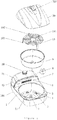
Figure 1 is a schematic view of the breakdown structure of one embodiment of the present invention. -
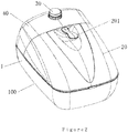
Figure 2 is a schematic view of the assembled structure ofFigure 1 . -
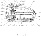
Figure 3 is a sectional structural view of the present invention. -
Figure 4 is a structural view of the pan body. -
Figure 5 is a structural view of the bracket. - The present invention is described in further detail with reference to the attached drawings and embodiments.
- As shown in
Figures 1-3 , an air heating type cooking pan consists of amachine body 100, acover body 20 and apan body 9; themachine body 100 is provided with aheating chamber 51 and a hotair generating device 60 which blows hot air into theheating chamber 51; one side of theheating chamber 51 is open; thepan body 9 is placed in theheating chamber 51 from the opened side of theheating chamber 51, and thecover body 20 covers outer side the opening of theheating chamber 51. Wherein, the air heating type cooking pan also consists of a rotary mechanism and at least three support roller wheels 4 (sixsupport roller wheels 4 in this embodiment); the rotary mechanism is disposed in themachine body 100, driving thepan body 9 to rotate via a driving member. The rotary mechanism consists of a motor, for example a turntable motor 50, and the motor shaft 501 of the turntable motor 50 is directly connected to thepan body 9 and drives the pan body 9to rotate. A plurality ofsupport roller wheels 4 are circumferentially distributed and located between the bottom of thepan body 9 and theheating chamber 51. - As a further specific solution, the driving member can be a non-round
rotary head 2, as shown inFigure 4 : a polygonal rotary head, the non-roundrotary head 2 is located at the bottom in theheating chamber 51; the bottom of thepan body 9 is provided with anon-round groove 91 with a shape and a size corresponding to thenon-round rotary head 2; the non-roundrotary head 2 is matched withnon-round groove 91 in an inserting way. Preferably, the non-roundrotary head 2 is disposed at the center of the bottom of theheating chamber 51, and thenon-round groove 91 is disposed at the center of the bottom of the pan body. The turntable motor 50 is located on the outer side of the bottom of theheating chamber 51; the motor shaft 501 penetrates through the bottom of theheating chamber 51 and is connected with the non-roundrotary head 2; during rotary working, the turntable motor 50 drives the non-roundrotary head 2 to rotate, and thepan body 9 rotates in theheating chamber 51 by the effect of the match of the roundrotary head 2 and thenon-round groove 91 such that the hot air blown uniformly exchanges heat with the food in thepan body 9. - The
support roller wheels 4 are circumferentially distributed at an equal interval around the motor shaft 501; thesupport roller wheels 4 are disposed on thewheel stand 3, and thewheel stand 3 and the bottom of theheating chamber 51 are fixed. In this way, therotary pan body 9 can smoothly move along the plurality ofsupport roller wheels 4 at the bottom. - An a more specific solution, as shown in
Figure 1 , themachine body 100 consists of abottom shell 1, a thermalinsulating tray 5, anupper shell 40 and alateral plate 7; the thermalinsulating tray 5 and theupper shell 40 are respectively disposed on thebottom shell 1; the top face of the thermalinsulating tray 5 is recessed downward to form theheating chamber 51 with an opened top; theupper shell 40 is located on one side of the opening of theheating chamber 51 and is connected with thelateral plate 7; and the surface of thelateral plate 7 is provided with ahot air outlet 71. - From the sectional structure of
Figure 3 , it can be seen that, the hotair generating device 60 is disposed in the space surrounded by thebottom shell 1 and theupper shell 40; the hotair generating device 60 consists of acentrifuge wind wheel 601, a blowingmotor 602, afixed mount 604, aheating element 605 and a thermal insulatingfairing 606; the fixedmount 604 is connected with the thermal insulatingtray 5; one end of the blowingmotor 602 is connected with the outer side of thefixed mount 604, while the other end faces an air suction opening on thebottom shell 1; thecentrifuge wind wheel 601 is disposed on the inner side of thefixed mount 604 and is in connection with the blowingmotor 602 in a transmission way; theheating element 605 is disposed at the upper end of the fixedmount 604 and close to thehot air outlet 71; the thermal insulatingfairing 606 is fixed at the upper end of the fixed mount and located on the outer side of theheating element 605; the thermal insulatingfairing 606 contains the heating element inside and together with fixed mount forms a hot air channel; and the port of the hot air channel corresponds to thehot air outlet 71. Theheating element 605 is of PTC (Positive Temperature Coefficient) material; during working, driven by thecentrifuge wind wheel 601, cold air enters the machine body via an external suction opening, quickly heated by the PTC heating element and then converted into the hot air; guided by the thermal insulatingfairing 606, the hot air enters theheating chamber 51 via theair outlet 71 to exchange heat with the food in thepan body 9 of theheating chamber 51. - An
air channel 11 is formed between thebottom shell 1 and the thermal insulatingtray 5; theair channel 11 communicates with the air suction opening of thecentrifuge wind wheel 601; the surface of theheating chamber 51 is provided with a hotair recycling hole 52; and the hotair recycling hole 52 connects theheating chamber 51 and theair channel 11. - During heating, the
centrifuge wind wheel 601 rotates at a high speed; negative pressure is formed in theair channel 11; the hot air is sucked into theair channel 11 via the hotair recycling hole 52 after heating the food; next, the recycled hot air re-enters the hotair generating device 60 and is reheated and blown into theheating chamber 51 to heat thepan body 9. See the full-line arrow inFigure 3 . - The other end (namely the one facing the air suction opening) of the blowing
motor 602 is provided with radiatingfins 603, and theradiating fins 603 are in connection with the rotating shaft of the blowingmotor 602 in a transmission way. When the blowingmotor 602 works, theradiating fins 603 are driven to rotate; theradiating fins 603 help themachine body 100 suck external cold air into thebottom shell 1; the cold air passes the surface of the blowingmotor 602 and then is exhausted out of the bottom shell via the exhaust outlet. See the dotted-line arrow inFigure 3 . Thus, the blowingmotor 602 is cooled, and the service life of theblower motor 602 is effectively enhanced. - As shown in
Figure 3 , thehot air outlet 71 is located on thelateral plate 7 and horizontally higher than thepan body 9, the top of thelateral plate 7 inclines towards theheating chamber 51 such that the hot air outlet points at the pan body and that the blown air hot fully heats the food at the bottom of thepan body 9; the surface of thelateral plate 7 is also provided with alamp body 6; thecover body 20 is a transparent cover; and the top of thecover body 20 is provided with ahandle 201. - The
upper shell 40 is internally provided with atimer 301 and a microswitch 81; the adjusting shaft 302 of thetimer 301 extends out of theupper shell 40 to be connected with the adjustingknob 30. The user can control the time for heating the food by rotating the adjustingknob 30. The button of the microswitch 81 is connected with one end of a switchingdrive rod 8; the other end of the switchingdrive rod 8 extends out of thelateral plate 7; in the process that thecover body 20 is closed downward, thecover body 20 triggers the switchingdrive rod 8, and then the microswitch 81 is closed. The microswitch can be connected to the power circuit so as to ensure that the machine stops working when the cover body is opened, thus preventing the hot air from directly blowing user. The use is safer. - The present invention also consists of a
bracket 10; thebracket 10 is disposed in thepan body 9; thebracket 10 consists of abracket mesh 101, a short-leg rack 102 and a long-leg rack 103; the short-leg rack 102 and the long-leg rack 103 are respectively disposed on the upper and lower surfaces of thebracket mesh 101. Thebracket 10 is optional (for example, used during food baking). - Working principle: The cold air enters the machine body from the outer side, is guided by the
centrifuge wind wheel 601, quickly heated by the PTC heating element and then converted into the hot air; the hot air is guided by the thermal insulating fairing 606 to enter theheating chamber 51 and exchanges heat with the food in therotating pan body 9 in theheating chamber 51; wherein, the motor shaft 501 of the turntable motor 50 drives thepan body 9 to rotate via the driving member, and thepan body 9 rotates more smoothly when rotating along the bottomsupport roller wheels 4. - In the air heating type cooking pan of the present invention, the pan body is set to self-rotate in the heating chamber through the rotary mechanism to uniformly heat the food in the pan body; the self-rotating pan body does not use the traditional stirring paddle and therefore can uniformly heat the food in the pan even during frying and baking food, and it is easy to clean.
Claims (9)
- An air heating type cooking pan, comprising a machine body (100), a cover body (20) and a pan body (9); said machine body (100) being provided with a heating chamber (51) and a hot air generating device (60) which blows hot air into said heating chamber (51), said pan body (9) being disposed in said heating chamber (51); wherein said air heating type cooking pan comprises a turntable motor (50) and at least three support roller wheels (4); said turntable motor (50) is disposed in said machine body (100); a motor shaft (501) of said turntable motor (50) drives said pan body (9) to rotate via a driving member; said at least three support roller wheels (4) are circumferentially distributed and located between the bottom of said pan body (9) and the bottom of said heating chamber (51); characterised in that said machine body (100) comprises a bottom shell (1), a thermal insulating tray (5), an upper shell (40) and a lateral plate (7); the thermal insulating tray (5) and the upper shell (40) are respectively disposed on the bottom shell (1); the top face of the thermal insulating tray (5) is recessed downward to form the heating chamber (51) with an opened top; the upper shell (40) is located on one side of the opening of the heating chamber (51) and is connected with the lateral plate (7); and the surface of the lateral plate (7) is provided with a hot air outlet (71); the top of the lateral plate (7) inclines towards said heating chamber (51).
- The air heating type cooking pan according to claim 1, characterized in that, said driving member is a non-round rotary head (2); the non-round rotary head (2) is located at the bottom in the heating chamber (51); the bottom of the pan body (9) is provided with a non-round groove (91) corresponding to the non-round rotary head (2); the non-round rotary head (2) and the non-round groove (91) are matched in an inserting way; said turntable motor (50) is located on the outer side of the bottom of the heating chamber (51); the motor shaft (501) penetrates the bottom of the heating chamber (51) to be connected with the non-round rotary head (2).
- The air heating type cooking pan according to claim 2, characterized in that, said support roller wheels (4) are circumferentially distributed at an equal interval around the motor shaft (501); the support roller wheels (4) are disposed on the wheel stand (3), and the wheel stand (3) and the bottom of the heating chamber (51) are fixed.
- The air heating type cooking pan according to claim 1, characterized in that, said hot air generating device (60) is disposed in the space surrounded by the bottom shell (1) and the upper shell (40); said hot air generating device (60) consists of a centrifuge wind wheel (601), a blowing motor (602), a fixed mount (604), a heating element (605) and a thermal insulating fairing (606); said fixed mount (604) is connected with said thermal insulating tray (5); the front end of said blowing motor (602) is connected with the outer side of said fixed mount (604), while the other end faces an air suction opening on the bottom shell (1); the centrifuge wind wheel (601) is disposed on the inner side of the fixed mount (604) and is in connection with the blowing motor (602) in a transmission way; the heating element (605) is disposed at the upper end of the fixed mount (604) and close to the hot air outlet (71); the thermal insulating fairing (606) is fixed at the upper end of the fixed mount and located on the outer side of the heating element (605); the thermal insulating fairing (606) contains the heating element inside and together with fixed mount forms a hot air channel; and the port of the hot air channel corresponds to the hot air outlet (71).
- The air heating type cooking pan according to claim 4, characterized in that, an air channel (11) is formed between said bottom shell (1) and said thermal insulating tray (5); said air channel (11) communicates with said air suction opening of the centrifuge wind wheel (601); the surface of said heating chamber (51) is provided with a hot air recycling hole (52); and said hot air recycling hole (52) connects said heating chamber (51) and said air channel (11).
- The air heating type cooking pan according to claim 4, characterized in that, the rear end of said blowing motor (602) is provided with radiating fins (603), and said radiating fins (603) are in connection with a rotating shaft of said blowing motor (602) in a transmission way.
- The air heating type cooking pan according to claim 1, characterized in that, the surface of said lateral plate (7) is also provided with a lamp body (6); said cover body (20) is a transparent cover; and the top of said cover body (20) is provided with a handle (201).
- The air heating type cooking pan according to claim 1, characterized in that, said upper shell (40) is internally provided with a timer (301) and a microswitch (81); an adjusting shaft (302) of said timer (301) extends out of the upper shell (40) to connect the adjusting knob (30); a button of said microswitch (81) is connected with one end of a switching drive rod (8); the other end of said switching drive rod (8) extends out of said lateral plate (7); in the process that the cover body (20) is closed downward, the cover body (20) triggers the switching drive rod (8), and then the microswitch (81) is closed.
- The air heating type cooking pan according to claim 1, characterized by also comprising a bracket (10); the bracket (10) being disposed in the pan body (9); the bracket (10) comprising a bracket mesh (101), a short-leg rack (102) and a long-leg rack (103); the short-leg rack (102) and the long-leg rack (103) being respectively disposed on the upper and lower surfaces of the bracket mesh (101).
Applications Claiming Priority (2)
| Application Number | Priority Date | Filing Date | Title |
|---|---|---|---|
| CN201310231135.4A CN103271632B (en) | 2013-06-10 | 2013-06-10 | Air heating cooking pot |
| PCT/CN2014/079357 WO2014198199A1 (en) | 2013-06-10 | 2014-06-06 | Air heating type cooking pan |
Publications (3)
| Publication Number | Publication Date |
|---|---|
| EP3009054A1 EP3009054A1 (en) | 2016-04-20 |
| EP3009054A4 EP3009054A4 (en) | 2017-03-29 |
| EP3009054B1 true EP3009054B1 (en) | 2018-10-10 |
Family
ID=49053869
Family Applications (1)
| Application Number | Title | Priority Date | Filing Date |
|---|---|---|---|
| EP14810884.8A Active EP3009054B1 (en) | 2013-06-10 | 2014-06-06 | Air heating type cooking pan |
Country Status (3)
| Country | Link |
|---|---|
| EP (1) | EP3009054B1 (en) |
| CN (1) | CN103271632B (en) |
| WO (1) | WO2014198199A1 (en) |
Families Citing this family (11)
| Publication number | Priority date | Publication date | Assignee | Title |
|---|---|---|---|---|
| CN103271632B (en) * | 2013-06-10 | 2015-05-13 | 麦甜洪 | Air heating cooking pot |
| CN205197818U (en) * | 2015-01-15 | 2016-05-04 | 皇家飞利浦有限公司 | A device for preparing food raw material |
| CN104799679A (en) * | 2015-05-12 | 2015-07-29 | 奉化科创科技服务有限公司 | Electric cooker control method |
| IT201600082900A1 (en) * | 2016-08-05 | 2018-02-05 | De Longhi Appliances Srl | AUTONOMOUS APPARATUS FOR COOKING FOOD AND ITS METHOD |
| CN107019411B (en) * | 2017-05-10 | 2022-06-28 | 佛山市顺德区龙江镇旗龙电器有限公司 | Multifunctional cooker |
| CN111248771A (en) * | 2020-03-27 | 2020-06-09 | 锐莫(佛山)电器科技有限公司 | Cooking utensil |
| CN112545137A (en) * | 2020-12-07 | 2021-03-26 | 珠海格力电器股份有限公司 | Lunch box |
| CN112493878B (en) * | 2020-12-22 | 2022-04-19 | 广东美的厨房电器制造有限公司 | Cooking device |
| CN112715823B (en) * | 2020-12-24 | 2023-08-01 | 深圳技术大学 | Fixed oxygen blowing streamline shovel of large-scale cooking robot |
| CN113040593A (en) * | 2021-04-06 | 2021-06-29 | 张璟钰 | Electric heating pot |
| CN113133685B (en) * | 2021-04-22 | 2022-02-01 | 九阳股份有限公司 | High-efficiency hot air cooking device |
Family Cites Families (16)
| Publication number | Priority date | Publication date | Assignee | Title |
|---|---|---|---|---|
| US5466912A (en) * | 1993-04-13 | 1995-11-14 | American Harvest, Inc. | Convection oven |
| US6265697B1 (en) * | 2000-07-03 | 2001-07-24 | Su Yung Sen | Rotisserie oven with orbiting spit drive gear |
| ITMI20032576A1 (en) * | 2003-12-23 | 2005-06-24 | De Longhi Spa | FRYER |
| IT1390860B1 (en) * | 2008-09-29 | 2011-10-19 | De Longhi Spa | FRYER AND COOKING PROCEDURE |
| CN201349984Y (en) * | 2008-12-30 | 2009-11-25 | 周林斌 | Multifunctional baking pan |
| CN201691742U (en) * | 2010-01-25 | 2011-01-05 | 宁波煜新电器有限公司 | Air baking pan |
| CN202051500U (en) * | 2011-02-15 | 2011-11-30 | 周林斌 | Multifunctional rotating fry pan |
| CN202287722U (en) * | 2011-09-01 | 2012-07-04 | 周林斌 | Rotary multifunctional frying pan |
| CN202408543U (en) * | 2012-02-10 | 2012-09-05 | 谭正华 | Dual-purpose steaming rack |
| CN102727104A (en) * | 2012-06-11 | 2012-10-17 | 周林斌 | Air flow roasting pan |
| CN102764063A (en) * | 2012-07-05 | 2012-11-07 | 周林斌 | Food stirring method of rotary multifunctional frying pan |
| KR101303685B1 (en) * | 2012-10-15 | 2013-09-23 | (주)보센인터내셔널 | A hot air heating roaster |
| CN102961055B (en) * | 2012-11-30 | 2014-12-10 | 周林斌 | Codirectional stirring oven and related method thereof |
| CN103006087A (en) * | 2012-12-26 | 2013-04-03 | 张毅蔚 | Rotary multifunctional oven and method thereof |
| CN203290707U (en) * | 2013-06-10 | 2013-11-20 | 麦甜洪 | Air-heating-type cooking pot |
| CN103271632B (en) * | 2013-06-10 | 2015-05-13 | 麦甜洪 | Air heating cooking pot |
-
2013
- 2013-06-10 CN CN201310231135.4A patent/CN103271632B/en active Active
-
2014
- 2014-06-06 EP EP14810884.8A patent/EP3009054B1/en active Active
- 2014-06-06 WO PCT/CN2014/079357 patent/WO2014198199A1/en active Application Filing
Also Published As
| Publication number | Publication date |
|---|---|
| CN103271632A (en) | 2013-09-04 |
| CN103271632B (en) | 2015-05-13 |
| EP3009054A1 (en) | 2016-04-20 |
| EP3009054A4 (en) | 2017-03-29 |
| WO2014198199A1 (en) | 2014-12-18 |
Similar Documents
| Publication | Publication Date | Title |
|---|---|---|
| EP3009054B1 (en) | Air heating type cooking pan | |
| CN204580991U (en) | Multi-functional air is complained and quarrel loudly | |
| CN204133291U (en) | A kind of air fryer | |
| CN204734374U (en) | Air is complained and quarrel loudly | |
| CN204016055U (en) | Air is complained and quarrel loudly | |
| US20110120319A1 (en) | Low-oil fryer and heating cover thereof | |
| CN203168843U (en) | Electric pressure utensil with air cooling mechanism | |
| CN101816521A (en) | Glass oven | |
| CN104545513B (en) | A kind of electric oven | |
| CN205849309U (en) | A kind of air fryer | |
| CN202136205U (en) | Frying pan | |
| CN204292889U (en) | Air heat pan | |
| CN203539136U (en) | Air fryer | |
| CN103381063B (en) | Positive and negative rotation frying pan and using method thereof | |
| CN103239149B (en) | Multi-function oven | |
| CN203290707U (en) | Air-heating-type cooking pot | |
| CN202537251U (en) | Suspended multi-functional baking oven | |
| CN215724830U (en) | Three-dimensional drying room | |
| CN209564021U (en) | A kind of air ovens | |
| CN211372994U (en) | Desktop type pottery stoving case | |
| CN202908541U (en) | Novel air barbecuing machine | |
| CN209966160U (en) | Electric oven with heated air circulation function | |
| CN219594384U (en) | Air fryer oven | |
| CN102589016B (en) | Multi-function convection oven | |
| CN207081284U (en) | Non- explosion-proof baking machine |
Legal Events
| Date | Code | Title | Description |
|---|---|---|---|
| PUAI | Public reference made under article 153(3) epc to a published international application that has entered the european phase |
Free format text: ORIGINAL CODE: 0009012 |
|
| 17P | Request for examination filed |
Effective date: 20151230 |
|
| AK | Designated contracting states |
Kind code of ref document: A1 Designated state(s): AL AT BE BG CH CY CZ DE DK EE ES FI FR GB GR HR HU IE IS IT LI LT LU LV MC MK MT NL NO PL PT RO RS SE SI SK SM TR |
|
| AX | Request for extension of the european patent |
Extension state: BA ME |
|
| DAX | Request for extension of the european patent (deleted) | ||
| A4 | Supplementary search report drawn up and despatched |
Effective date: 20170227 |
|
| RIC1 | Information provided on ipc code assigned before grant |
Ipc: A47J 37/06 20060101AFI20170221BHEP |
|
| REG | Reference to a national code |
Ref country code: DE Ref legal event code: R079 Ref document number: 602014033951 Country of ref document: DE Free format text: PREVIOUS MAIN CLASS: A47J0027000000 Ipc: A47J0037060000 |
|
| GRAP | Despatch of communication of intention to grant a patent |
Free format text: ORIGINAL CODE: EPIDOSNIGR1 |
|
| STAA | Information on the status of an ep patent application or granted ep patent |
Free format text: STATUS: GRANT OF PATENT IS INTENDED |
|
| RIC1 | Information provided on ipc code assigned before grant |
Ipc: A47J 37/06 20060101AFI20180404BHEP |
|
| INTG | Intention to grant announced |
Effective date: 20180426 |
|
| GRAS | Grant fee paid |
Free format text: ORIGINAL CODE: EPIDOSNIGR3 |
|
| GRAA | (expected) grant |
Free format text: ORIGINAL CODE: 0009210 |
|
| STAA | Information on the status of an ep patent application or granted ep patent |
Free format text: STATUS: THE PATENT HAS BEEN GRANTED |
|
| AK | Designated contracting states |
Kind code of ref document: B1 Designated state(s): AL AT BE BG CH CY CZ DE DK EE ES FI FR GB GR HR HU IE IS IT LI LT LU LV MC MK MT NL NO PL PT RO RS SE SI SK SM TR |
|
| REG | Reference to a national code |
Ref country code: GB Ref legal event code: FG4D |
|
| REG | Reference to a national code |
Ref country code: CH Ref legal event code: EP Ref country code: AT Ref legal event code: REF Ref document number: 1050243 Country of ref document: AT Kind code of ref document: T Effective date: 20181015 |
|
| REG | Reference to a national code |
Ref country code: IE Ref legal event code: FG4D |
|
| REG | Reference to a national code |
Ref country code: DE Ref legal event code: R096 Ref document number: 602014033951 Country of ref document: DE |
|
| REG | Reference to a national code |
Ref country code: NL Ref legal event code: MP Effective date: 20181010 |
|
| REG | Reference to a national code |
Ref country code: LT Ref legal event code: MG4D |
|
| REG | Reference to a national code |
Ref country code: AT Ref legal event code: MK05 Ref document number: 1050243 Country of ref document: AT Kind code of ref document: T Effective date: 20181010 |
|
| PG25 | Lapsed in a contracting state [announced via postgrant information from national office to epo] |
Ref country code: NL Free format text: LAPSE BECAUSE OF FAILURE TO SUBMIT A TRANSLATION OF THE DESCRIPTION OR TO PAY THE FEE WITHIN THE PRESCRIBED TIME-LIMIT Effective date: 20181010 |
|
| PG25 | Lapsed in a contracting state [announced via postgrant information from national office to epo] |
Ref country code: LV Free format text: LAPSE BECAUSE OF FAILURE TO SUBMIT A TRANSLATION OF THE DESCRIPTION OR TO PAY THE FEE WITHIN THE PRESCRIBED TIME-LIMIT Effective date: 20181010 Ref country code: ES Free format text: LAPSE BECAUSE OF FAILURE TO SUBMIT A TRANSLATION OF THE DESCRIPTION OR TO PAY THE FEE WITHIN THE PRESCRIBED TIME-LIMIT Effective date: 20181010 Ref country code: BG Free format text: LAPSE BECAUSE OF FAILURE TO SUBMIT A TRANSLATION OF THE DESCRIPTION OR TO PAY THE FEE WITHIN THE PRESCRIBED TIME-LIMIT Effective date: 20190110 Ref country code: HR Free format text: LAPSE BECAUSE OF FAILURE TO SUBMIT A TRANSLATION OF THE DESCRIPTION OR TO PAY THE FEE WITHIN THE PRESCRIBED TIME-LIMIT Effective date: 20181010 Ref country code: LT Free format text: LAPSE BECAUSE OF FAILURE TO SUBMIT A TRANSLATION OF THE DESCRIPTION OR TO PAY THE FEE WITHIN THE PRESCRIBED TIME-LIMIT Effective date: 20181010 Ref country code: PL Free format text: LAPSE BECAUSE OF FAILURE TO SUBMIT A TRANSLATION OF THE DESCRIPTION OR TO PAY THE FEE WITHIN THE PRESCRIBED TIME-LIMIT Effective date: 20181010 Ref country code: NO Free format text: LAPSE BECAUSE OF FAILURE TO SUBMIT A TRANSLATION OF THE DESCRIPTION OR TO PAY THE FEE WITHIN THE PRESCRIBED TIME-LIMIT Effective date: 20190110 Ref country code: IS Free format text: LAPSE BECAUSE OF FAILURE TO SUBMIT A TRANSLATION OF THE DESCRIPTION OR TO PAY THE FEE WITHIN THE PRESCRIBED TIME-LIMIT Effective date: 20190210 Ref country code: FI Free format text: LAPSE BECAUSE OF FAILURE TO SUBMIT A TRANSLATION OF THE DESCRIPTION OR TO PAY THE FEE WITHIN THE PRESCRIBED TIME-LIMIT Effective date: 20181010 Ref country code: AT Free format text: LAPSE BECAUSE OF FAILURE TO SUBMIT A TRANSLATION OF THE DESCRIPTION OR TO PAY THE FEE WITHIN THE PRESCRIBED TIME-LIMIT Effective date: 20181010 |
|
| PG25 | Lapsed in a contracting state [announced via postgrant information from national office to epo] |
Ref country code: SE Free format text: LAPSE BECAUSE OF FAILURE TO SUBMIT A TRANSLATION OF THE DESCRIPTION OR TO PAY THE FEE WITHIN THE PRESCRIBED TIME-LIMIT Effective date: 20181010 Ref country code: PT Free format text: LAPSE BECAUSE OF FAILURE TO SUBMIT A TRANSLATION OF THE DESCRIPTION OR TO PAY THE FEE WITHIN THE PRESCRIBED TIME-LIMIT Effective date: 20190210 Ref country code: AL Free format text: LAPSE BECAUSE OF FAILURE TO SUBMIT A TRANSLATION OF THE DESCRIPTION OR TO PAY THE FEE WITHIN THE PRESCRIBED TIME-LIMIT Effective date: 20181010 Ref country code: RS Free format text: LAPSE BECAUSE OF FAILURE TO SUBMIT A TRANSLATION OF THE DESCRIPTION OR TO PAY THE FEE WITHIN THE PRESCRIBED TIME-LIMIT Effective date: 20181010 Ref country code: GR Free format text: LAPSE BECAUSE OF FAILURE TO SUBMIT A TRANSLATION OF THE DESCRIPTION OR TO PAY THE FEE WITHIN THE PRESCRIBED TIME-LIMIT Effective date: 20190111 |
|
| REG | Reference to a national code |
Ref country code: DE Ref legal event code: R097 Ref document number: 602014033951 Country of ref document: DE |
|
| PG25 | Lapsed in a contracting state [announced via postgrant information from national office to epo] |
Ref country code: CZ Free format text: LAPSE BECAUSE OF FAILURE TO SUBMIT A TRANSLATION OF THE DESCRIPTION OR TO PAY THE FEE WITHIN THE PRESCRIBED TIME-LIMIT Effective date: 20181010 Ref country code: DK Free format text: LAPSE BECAUSE OF FAILURE TO SUBMIT A TRANSLATION OF THE DESCRIPTION OR TO PAY THE FEE WITHIN THE PRESCRIBED TIME-LIMIT Effective date: 20181010 Ref country code: IT Free format text: LAPSE BECAUSE OF FAILURE TO SUBMIT A TRANSLATION OF THE DESCRIPTION OR TO PAY THE FEE WITHIN THE PRESCRIBED TIME-LIMIT Effective date: 20181010 |
|
| PLBE | No opposition filed within time limit |
Free format text: ORIGINAL CODE: 0009261 |
|
| STAA | Information on the status of an ep patent application or granted ep patent |
Free format text: STATUS: NO OPPOSITION FILED WITHIN TIME LIMIT |
|
| PG25 | Lapsed in a contracting state [announced via postgrant information from national office to epo] |
Ref country code: SK Free format text: LAPSE BECAUSE OF FAILURE TO SUBMIT A TRANSLATION OF THE DESCRIPTION OR TO PAY THE FEE WITHIN THE PRESCRIBED TIME-LIMIT Effective date: 20181010 Ref country code: RO Free format text: LAPSE BECAUSE OF FAILURE TO SUBMIT A TRANSLATION OF THE DESCRIPTION OR TO PAY THE FEE WITHIN THE PRESCRIBED TIME-LIMIT Effective date: 20181010 Ref country code: SM Free format text: LAPSE BECAUSE OF FAILURE TO SUBMIT A TRANSLATION OF THE DESCRIPTION OR TO PAY THE FEE WITHIN THE PRESCRIBED TIME-LIMIT Effective date: 20181010 Ref country code: EE Free format text: LAPSE BECAUSE OF FAILURE TO SUBMIT A TRANSLATION OF THE DESCRIPTION OR TO PAY THE FEE WITHIN THE PRESCRIBED TIME-LIMIT Effective date: 20181010 |
|
| 26N | No opposition filed |
Effective date: 20190711 |
|
| PG25 | Lapsed in a contracting state [announced via postgrant information from national office to epo] |
Ref country code: SI Free format text: LAPSE BECAUSE OF FAILURE TO SUBMIT A TRANSLATION OF THE DESCRIPTION OR TO PAY THE FEE WITHIN THE PRESCRIBED TIME-LIMIT Effective date: 20181010 |
|
| REG | Reference to a national code |
Ref country code: DE Ref legal event code: R119 Ref document number: 602014033951 Country of ref document: DE |
|
| PG25 | Lapsed in a contracting state [announced via postgrant information from national office to epo] |
Ref country code: MC Free format text: LAPSE BECAUSE OF FAILURE TO SUBMIT A TRANSLATION OF THE DESCRIPTION OR TO PAY THE FEE WITHIN THE PRESCRIBED TIME-LIMIT Effective date: 20181010 |
|
| REG | Reference to a national code |
Ref country code: CH Ref legal event code: PL |
|
| GBPC | Gb: european patent ceased through non-payment of renewal fee |
Effective date: 20190606 |
|
| REG | Reference to a national code |
Ref country code: BE Ref legal event code: MM Effective date: 20190630 |
|
| PG25 | Lapsed in a contracting state [announced via postgrant information from national office to epo] |
Ref country code: TR Free format text: LAPSE BECAUSE OF FAILURE TO SUBMIT A TRANSLATION OF THE DESCRIPTION OR TO PAY THE FEE WITHIN THE PRESCRIBED TIME-LIMIT Effective date: 20181010 |
|
| PG25 | Lapsed in a contracting state [announced via postgrant information from national office to epo] |
Ref country code: DE Free format text: LAPSE BECAUSE OF NON-PAYMENT OF DUE FEES Effective date: 20200101 Ref country code: GB Free format text: LAPSE BECAUSE OF NON-PAYMENT OF DUE FEES Effective date: 20190606 Ref country code: IE Free format text: LAPSE BECAUSE OF NON-PAYMENT OF DUE FEES Effective date: 20190606 |
|
| PG25 | Lapsed in a contracting state [announced via postgrant information from national office to epo] |
Ref country code: LI Free format text: LAPSE BECAUSE OF NON-PAYMENT OF DUE FEES Effective date: 20190630 Ref country code: CH Free format text: LAPSE BECAUSE OF NON-PAYMENT OF DUE FEES Effective date: 20190630 Ref country code: BE Free format text: LAPSE BECAUSE OF NON-PAYMENT OF DUE FEES Effective date: 20190630 Ref country code: LU Free format text: LAPSE BECAUSE OF NON-PAYMENT OF DUE FEES Effective date: 20190606 |
|
| PG25 | Lapsed in a contracting state [announced via postgrant information from national office to epo] |
Ref country code: CY Free format text: LAPSE BECAUSE OF FAILURE TO SUBMIT A TRANSLATION OF THE DESCRIPTION OR TO PAY THE FEE WITHIN THE PRESCRIBED TIME-LIMIT Effective date: 20181010 |
|
| PG25 | Lapsed in a contracting state [announced via postgrant information from national office to epo] |
Ref country code: HU Free format text: LAPSE BECAUSE OF FAILURE TO SUBMIT A TRANSLATION OF THE DESCRIPTION OR TO PAY THE FEE WITHIN THE PRESCRIBED TIME-LIMIT; INVALID AB INITIO Effective date: 20140606 Ref country code: MT Free format text: LAPSE BECAUSE OF FAILURE TO SUBMIT A TRANSLATION OF THE DESCRIPTION OR TO PAY THE FEE WITHIN THE PRESCRIBED TIME-LIMIT Effective date: 20181010 |
|
| PG25 | Lapsed in a contracting state [announced via postgrant information from national office to epo] |
Ref country code: MK Free format text: LAPSE BECAUSE OF FAILURE TO SUBMIT A TRANSLATION OF THE DESCRIPTION OR TO PAY THE FEE WITHIN THE PRESCRIBED TIME-LIMIT Effective date: 20181010 |
|
| PGFP | Annual fee paid to national office [announced via postgrant information from national office to epo] |
Ref country code: FR Payment date: 20230623 Year of fee payment: 10 |