EP3007131A1 - Verfahren zum raffinieren der kalibrierung eines abbildungssystems - Google Patents
Verfahren zum raffinieren der kalibrierung eines abbildungssystems Download PDFInfo
- Publication number
- EP3007131A1 EP3007131A1 EP15177700.0A EP15177700A EP3007131A1 EP 3007131 A1 EP3007131 A1 EP 3007131A1 EP 15177700 A EP15177700 A EP 15177700A EP 3007131 A1 EP3007131 A1 EP 3007131A1
- Authority
- EP
- European Patent Office
- Prior art keywords
- calibration
- lookup table
- data
- image
- imaging system
- Prior art date
- Legal status (The legal status is an assumption and is not a legal conclusion. Google has not performed a legal analysis and makes no representation as to the accuracy of the status listed.)
- Withdrawn
Links
Images


Classifications
-
- G—PHYSICS
- G06—COMPUTING; CALCULATING OR COUNTING
- G06T—IMAGE DATA PROCESSING OR GENERATION, IN GENERAL
- G06T15/00—3D [Three Dimensional] image rendering
-
- G—PHYSICS
- G06—COMPUTING; CALCULATING OR COUNTING
- G06T—IMAGE DATA PROCESSING OR GENERATION, IN GENERAL
- G06T7/00—Image analysis
- G06T7/50—Depth or shape recovery
- G06T7/55—Depth or shape recovery from multiple images
- G06T7/593—Depth or shape recovery from multiple images from stereo images
-
- G—PHYSICS
- G03—PHOTOGRAPHY; CINEMATOGRAPHY; ANALOGOUS TECHNIQUES USING WAVES OTHER THAN OPTICAL WAVES; ELECTROGRAPHY; HOLOGRAPHY
- G03B—APPARATUS OR ARRANGEMENTS FOR TAKING PHOTOGRAPHS OR FOR PROJECTING OR VIEWING THEM; APPARATUS OR ARRANGEMENTS EMPLOYING ANALOGOUS TECHNIQUES USING WAVES OTHER THAN OPTICAL WAVES; ACCESSORIES THEREFOR
- G03B35/00—Stereoscopic photography
-
- G—PHYSICS
- G06—COMPUTING; CALCULATING OR COUNTING
- G06T—IMAGE DATA PROCESSING OR GENERATION, IN GENERAL
- G06T7/00—Image analysis
- G06T7/80—Analysis of captured images to determine intrinsic or extrinsic camera parameters, i.e. camera calibration
-
- G—PHYSICS
- G06—COMPUTING; CALCULATING OR COUNTING
- G06T—IMAGE DATA PROCESSING OR GENERATION, IN GENERAL
- G06T7/00—Image analysis
- G06T7/80—Analysis of captured images to determine intrinsic or extrinsic camera parameters, i.e. camera calibration
- G06T7/85—Stereo camera calibration
-
- G—PHYSICS
- G06—COMPUTING; CALCULATING OR COUNTING
- G06T—IMAGE DATA PROCESSING OR GENERATION, IN GENERAL
- G06T2207/00—Indexing scheme for image analysis or image enhancement
- G06T2207/10—Image acquisition modality
- G06T2207/10016—Video; Image sequence
- G06T2207/10021—Stereoscopic video; Stereoscopic image sequence
-
- G—PHYSICS
- G06—COMPUTING; CALCULATING OR COUNTING
- G06T—IMAGE DATA PROCESSING OR GENERATION, IN GENERAL
- G06T2207/00—Indexing scheme for image analysis or image enhancement
- G06T2207/30—Subject of image; Context of image processing
- G06T2207/30004—Biomedical image processing
- G06T2207/30036—Dental; Teeth
Definitions
- the invention relates to three-dimensional scanning, and more particularly to techniques for addressing artifacts in derivations of three-dimensional data.
- Acquisition of data for three-dimensional imaging generally includes artifacts related to, for example, the imaging subject, ambient conditions, and inherent properties of the optical and electronic systems used for data acquisition.
- General calibration techniques may employ direct measurement of known targets to characterize these errors, as well as mathematical modeling of non-ideal aspects of an imaging system.
- modeling techniques can present difficult characterization challenges and may fail to capture actual sources of imaging artifacts.
- brute force calibration may be time consuming, and typically requires a specialized, sensitive hardware platform.
- Brute calibration also results in very large calibration files, particularly for the multi-dimensional data sets used in three-dimensional imaging. The selection among these existing alternatives will generally depend on the characteristics of the system being calibrated, and usually forces some degree of compromise on a designer. In multi-aperture devices and other systems having more than one optical channel, the selection of an appropriate calibration regime may become more difficult because each channel may present different characteristics affecting calibration.
- Performance of a three-dimensional imaging system, and calibration thereof, is improved through the use of model-based calibration and lookup tables to resolve depth according to, e.g., x-displacement, y-displacement, and/or image disparity data.
- the lookup table(s) stores localized parameterization data used to calculate calibrated results.
- a technique for calibrating a three-dimensional imaging system Described below is a technique for calibrating a three-dimensional imaging system. While the lookup tables and calibration techniques are described in reference to certain multi-aperture systems that use disparity information to recover depth, it will be understood that variations and alternative embodiments would be apparent to one of ordinary skill in the art and are intended to fall within the scope of this disclosure. For example, a system may employ time, differences in spatial frequency content, or any other criterion suitable for organizing and retrieving parameters used in encoding depth and calibration calculations.
- image generally refers to a set of two-dimensional pixels forming a two-dimensional view of a subject within an image plane.
- image set generally refers to a set of related two dimensional images that might be resolved into three-dimensional data. Typically, although not necessarily, this would include two or more images of a subject captured substantially simultaneously using different cameras or apertures, or two or more images of a subject captured from the same aperture at different times.
- point cloud generally refers to a set of three-dimensional points forming a three-dimensional view of the subject reconstructed from a number of two-dimensional views.
- a number of such point clouds may also be registered and combined into an aggregate point cloud constructed from images captured by a moving camera (or a moving subject).
- pixels generally refer to two-dimensional data and points generally refer to three-dimensional data, unless another meaning is specifically indicated or clear from the context.
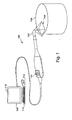
- Fig. 1 shows an image capture system.
- the system 100 may include a scanner 102 that captures images of a subject 104 within a field of view 106, and forwards the images to a computer 108, which may include a display 110 and one or more user input devices such as a mouse 112 or a keyboard 114.
- the scanner 102 may include any camera or camera system suitable for capturing images from which a three-dimensional point cloud may be recovered.
- the camera 102 may employ a multi-aperture system as disclosed, for example, in U.S. Pat. Pub. No. 20040155975 to Hart et al. , the entire contents of which is incorporated herein by reference. While Hart discloses one multi-aperture system, it will be appreciated that any multi-aperture, multi-pupil, multi-camera, or other multi-channel optical system suitable for reconstructing a three-dimensional point cloud from a number of two-dimensional images may similarly be employed.
- the scanner 102 may include a plurality of apertures including a center aperture positioned along a center optical axis of a lens and any associated imaging hardware.
- the scanner 102 may also, or instead, include a stereoscopic, triscopic or other multi-camera or other configuration in which a number of cameras or optical paths are maintained in fixed relation to one another to obtain two-dimensional images of an object from a number of slightly different perspectives.
- the scanner 102 may include suitable processing for deriving a three-dimensional point cloud from an image set or a number of image sets, or each two-dimensional image set may be transmitted to an external processor such as contained in the computer 108 described below.
- the scanner 102 may employ structured light, laser scanning, direct ranging, or any other technology suitable for acquiring three-dimensional data, or two-dimensional data that can be resolved into three-dimensional data.
- the scanner 102 is a handheld, freely positionable probe having at least one user input device, such as a button, lever, dial, thumb wheel, switch, or the like, for user control of the image capture system 100 such as starting and stopping scans.
- supplemental lighting systems may be usefully employed during image capture.
- environmental illumination may be enhanced with one or more spotlights, ring lights, or coaxial illumination sources illuminating the subject 104 to speed image acquisition and improve depth of field (or spatial resolution depth).
- the scanner 102 may also, or instead, include a strobe, flash, or other light source to supplement illumination of the subject 104 during image acquisition, or to provide illumination in different spectral bands.
- the subject 104 may be any object, collection of objects, portion of an object, or other subject matter. While illustrated in Fig. 1 as a simple geometric form, the subject 104 may include much more complex surfaces, and any number of separate elements.
- the subject 104 may include a tooth, a quadrant of teeth, or a full collection of teeth including two opposing arches from which a virtual dental impression is desired.
- the subject 104 may also, or instead, include a dental prosthesis such as an inlay, a crown, or any other dental prosthesis, implant, or the like.
- the subject 104 may include a dental model, such as a plaster cast, wax-up, impression, or negative impression of a tooth, teeth, soft tissue, or some combination of these.
- an optical or textured imaging agent may be applied to surfaces of the subject 104 to improve capture of three dimensional points.
- the subject 104 may be a human head, or a portion thereof, from which a three-dimensional model is desired for custom fitting of a hearing aid, eyeglasses, goggles, or the like.
- the subject 104 may be a physical model of an object for use in digital animation, such as a miniature, physical model for use in a three-dimensional digital animation process. From the preceding examples, it will be apparent that a system using the techniques described herein may be suitably adapted to a wide range of applications for relatively short range, high resolution, three-dimensional image acquisition.
- the field of view 106 may include a two-dimensional field of view of the camera 102. It will be appreciated that the term "field of view” as used in this paragraph, refers to a plane in the imaging environment rather than a plane within an optical sensor (such as film or sensors) where an image is captured. Though illustrated as a rectangle the field of view 106 may, for example, form a square, a circle, or any other geometry provided by the scanner 102. In general, the scanner 102 will have a depth of field or range of depth resolution that, together with the field of view 106, specifies a measurement volume of the scanner 102. The depth of field may vary with environmental conditions such as ambient light.
- the computer 108 may be, for example, a personal computer or other processing device.
- the computer 108 includes a personal computer with a dual 2.8GHz Opteron central processing unit, 2 gigabytes of random access memory, a TYAN Thunder K8WE motherboard, and a 250 gigabyte, 10,000 rpm hard drive.
- This system may be operated to capture approximately 1,500 points per image set in real time using the techniques described herein, and store an aggregated point cloud of over one million points.
- Other embodiments using commercially available, more performant hardware may capture approximately 3,000 points per image set in real time.
- the number of points per image in a particular embodiment may depend on a number of factors including density and configuration of sensors and other imaging hardware.
- processing capabilities of the computer 108 may vary according to the size of the subject 104, the speed of image acquisition, and the desired spatial resolution of three-dimensional points.
- the computer 108 may also include peripheral devices such as a keyboard 114, display 110, and mouse 112 for user interaction with the camera system 100.
- the display 110 may be a touch screen display capable of receiving user input through direct, physical interaction with the display 110.
- Communications between the computer 108 and the scanner 102 may use any suitable communications link including, for example, a wired connection or a wireless connection based upon, for example, IEEE 802.11 (also known as wireless Ethernet), BlueTooth, or any other suitable wireless standard using, e.g., a radio frequency, infrared, or other wireless communication medium.
- IEEE 802.11 also known as wireless Ethernet
- BlueTooth or any other suitable wireless standard using, e.g., a radio frequency, infrared, or other wireless communication medium.
- wireless image transmission from the scanner 102 to the computer 108 may be secured.
- the computer 108 may generate control signals to the scanner 102 which, in addition to image acquisition commands, may include conventional camera controls such as focus or zoom.
- the scanner 102 may acquire two-dimensional image sets while the scanner 102 is passed over a surface of the subject.
- the two-dimensional image sets may be forwarded to the computer 108 for derivation of three-dimensional point clouds.
- the three-dimensional data for each newly acquired two-dimensional image set may be derived and fitted to existing three-dimensional data using a number of different techniques.
- One useful example of such a technique is described in commonly-owned U.S. App. No. 11/270,135, filed on November 9, 2005 , the entire contents of which is incorporated herein by reference.
- this example is not limiting, and that the principles described herein may be applied to a wide range of three-dimensional image capture systems.
- Fig. 2 illustrates the coordinate systems for a multiaperture imaging system, such as the system described above.
- the term multiaperture is intended to refer to a single camera having two or more apertures (or pupils or the like), or two or more single-aperture cameras such as employed in stereoscopic imaging, or some combination of these.
- the disparity vector may be expressed, for example, in terms of displacement relative to a center channel, if any, for the camera 206.
- the disparity vector encodes depth, and in other three-dimensional imaging systems, this disparity vector may be replaced by one or more other measured quantities that encode depth.
- terms such as disparity vector, disparity value, and disparity data should be understood broadly to include any one or more scalar and/or vector quantities measured by a system to encode depth information.
- the world coordinates may be related to uncalibrated image set coordinates through a rotation and/or translation that can be characterized using a battery of calibration measurements with a hardware fixture.
- a target such as a planar target having a pattern may be moved through a variety of known positions and/or rotations relative to the camera 206 using a calibration bed (or similar hardware) while capturing image set coordinates.
- a number of models may be employed to correlate image set coordinate data to the camera cvordinafe(s).
- points in the measurement volume can be directly correlated to X w , Y w , and Z w values in world coordinates.
- a general goal of such calibration is to permit operational determination of a true distance from the camera 206 to a point on the subject 202, or to determine the world or camera coordinates of a point on the subject.
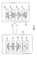
- Fig. 3 shows a process for lookup table construction and use.
- image data is acquired in an initial calibration from a known target in a number of calibration cycles, as shown in step 301.
- the calibration may be refined in subsequent processing steps 302, and results may be parameterized using image results (e.g., data from a scanner, and/or disparity data derived therefrom or other data encoding depth information) in combination with true position data (e.g., known target location and/or orientation, or known distance of a point from the camera) available from a calibration system, as shown in step 304.
- the true position data from the calibration system may include position data delivered from a calibration fixture, or obtained through processing of targets during one or more calibration cycles, or some combination of these.
- the parameterized results may be used to construct a lookup table, as shown in step 305.
- the lookup table may be employed to derive three-dimensional data from two-dimensional images captured by the image capture system, as shown in step 309.
- the objective of this process is to obtain true results for three-dimensional data, which may be advantageously realized, for example, as a system for obtaining real time, calibrated three-dimensional results through the use of a lookup table.
- the initial acquisition of calibration data of step 301 is now described in greater detail. Acquisition of data from a known target may be performed using a controlled calibration bed that moves the target a predetermined distance towards the instrument for each calibration cycle. For example, the calibration bed may move the target 25 microns closer to the instrument for each calibration cycle. At each distance, image set coordinates may be obtained.
- the camera 206 may include a center aperture, in which case calibration measurements may be used to capture extrinsic camera parameters, i.e., rotation and translation from world coordinates to camera coordinates for the collected set of points.
- multiaperture data may be expressed as x and y coordinates in the coordinate system of each sensor, along with disparity vectors that characterize displacement of a point for different apertures from the relevant point in a reference frame (e.g., the center aperture).
- the calibration may be performed on the reference frame, e.g., from the center channel or center aperture, with the resulting lookup table used to convert disparity data into X, Y, Z coordinates.
- a checkerboard or other target may be used.
- a target with a distinct center feature or other fiducial is desirable for calibrating an imaging system. Random patterns may also be employed to characterize image disparity fields.
- a hybrid target may also be employed including a number of fiducials, e.g., nine points equally distributed on a rectangular grid, along with a random pattern between the fiducials. This permits construction of a lookup table that accounts for processing artifacts of an image processing algorithm (such as an area-based, rather than point-based algorithm) along with other camera calibration.
- Such a target may, for example, permit correlation between center and side images as well as correlation between side images.
- a known arrangement of fiducials may be used to recover target position in the camera coordinate system (such as from the center channel image), and a random pattern may be used to recover plane points using side channel images.
- the recovered plane points may be orthogonally fitted with a plane, with orthogonal distance from the fitted plane providing a measurement of noise in the imaging system (e.g., due to noise in disparity estimation, lookup tables, and so forth). While verification of a lookup table is discussed in greater detail below, it is noted in this context that a difference between the plane identified using fiducials and the plane identified by applying the lookup table system to random elements of the hybrid target may serve as a validation or verification of a particular lookup table created according to the systems and methods described herein.
- target patterns such as random noise and/or fiducials may be projected onto a target, for example back projected by a digital data projector on a holographic diffuser, to permit use of different patterns within a calibration cycle or across a number of calibration cycles.
- a first calibration may be performed using arbitrary planar or three-dimensional calibration target locations and orientations. This first step, which may be performed using standard calibration techniques, may be employed to calibrate without recovery of depth-dependent terms.
- This calibration may be refined, as shown in step 302.
- a second calibration may use a sequence of planar calibration targets having arbitrary, unknown orientation and a known step increment (e.g., 200 microns) in an arbitrary, unknown direction.
- the second calibration step may be employed to recover a two-dimensional geometric distortion model including depth-dependent terms.
- this process may be employed to recover target orientation and motion, which may advantageously loosen restrictions on the corresponding calibration hardware.
- This calibration technique may be usefully employed in any optical system having at least one well-characterized optical channel (e.g., the center channel described above), that is, a channel conforming to one or more known distortion models suitable to parameterization.
- the calibration cycles for creation of a lookup table would sample an entire measurement volume using a Z increment at or near the desired resolution of a system.
- a dense lookup table with equidistant disparity values can be built after fitting disparity and depth points with the known function.
- a dense lookup table can be constructed analytically with equidistant disparity values after satisfactorily fitting disparity and depth points using the techniques described above. Stated inversely, it is possible to sample a disparity/depth space of a lookup-table-based system at a lower resolution, and analytical construct a full resolution lookup table.
- the calibration may be refined, for example, by enforcing a parallel target constraint with a Z dependent distortion model.
- the result of such a calibration refinement may include a set of points in the camera coordinate system along with relevant disparity data.
- the Z dependent distortion parameters may be determined.
- other model parameters useful for obtaining calibrated output may be derived such as camera focal length, image plane or processing mesh x-dependent terms, image plane or processing mesh y-dependent terms, and so forth.
- the disparities may also be interpolated onto a fixed processing mesh for the well characterized channel (e.g., center channel of a multiaperture system) to reduce processing time ordinarily associated with a full calibration.
- Z-dependent distortion in acquired images can be introduced by various lenses and/or off-axis ray paths through an optical system. While the distortion of an optical system is typically dominated by radial and de-center distortions, which suffice for most camera calibration purposes, the depth-dependent distortion may be important for accurate camera calibration. In one aspect, certain dominant terms such as radial distortion may be addressed by a first calibration, and one or more depth-dependent terms can be added in subsequent calibration refinements.
- results from the calibration cycles may be parameterized for easier and more flexible use of the lookup table.
- a number of parameterization models may be usefully employed. While the examples below generally employ a disparity vector as a lookup table input, it will be appreciated that a z value may be calculated from the acquired data, and the x, y, and (calculated) z values from the acquired image may alternatively be used as indices for a lookup table, with suitable adaptations to subsequent processing.
- data from each calibration target location/orientation may be characterized as an array, or number of arrays containing disparity values for each x and y location in a processing mesh for a field of view of the camera.
- a scalar characterization of the disparity such as an x-axis disparity (relative to the field of view), d x , a y-axis disparity (relative to the field of view), dy ,or
- the lookup table may be deployed as a direct lookup of camera coordinates ⁇ X c , Y c , Zc ⁇ , as described in more detail below.
- true values such as the Z value
- a disparity parameter such as one of the scalar disparity quantities noted above
- Z is related to d y ( d x , or
- data may be fitted to a general relationship: Z x y d y ⁇ p 1 x y p 2 x y + d y x y + p 3 x y
- p may be stored in a lookup table indexed according to x, y, and d y so that uncalibrated image results can be applied to obtain the parameters for Eq. 4, which may in turn be employed to calculate a value for Z.
- Z refers generally to a depth variable, which may in a particular implementation correspond to a world coordinate, a camera coordinate, a camera depth, or any other suitable quantity reflecting depth data. It should also be understood that the selection of a y-coordinate disparity is illustrative only, and in no way limits the scope of this disclosure.
- certain physical camera systems may exhibit predominately y-dependent disparity vectors, such as where apertures are oriented collinearly along the y-dimension of the processing mesh.
- physical attributes of a camera system e.g. pupil aberration
- a parameterized model may account for such known, regular distortion patterns, by fitting calibration data acquisition results to one or more corresponding models, thus providing a more compact lookup table, fewer calibration measurements, or both.
- a first gross calibration may address Z-independent radial or tangential distortion, with additional terms added to parameterization in a subsequent fine calibration step.
- the parameter surface itself may be modeled.
- a parameterized parameter model may substantially reduce the size of a lookup table calibration system in terms of physical memory or storage.
- empirically a z-dependent distortion component for an embodiment of the image capture system 100 described above contains dominant terms of the form: ⁇ ⁇ z Z ⁇ ⁇ 1 + ⁇ 2 Z + ⁇ 3 ⁇ Z
- a lookup table may be created for the above calibration data and models by fitting calibration test results to one or more models to obtain model parameters as described above using any suitable fitting, error minimization, or other techniques.
- the construction of the lookup table will depend upon specific implementations, some of which are discussed in greater detail below.
- the lookup table implementation for an image capture system will provide a mechanism for relating newly acquired data from the image capture system to coordinate data for surface points on an imaging subject.
- calibrating an image system in this manner permits localization of a camera model that is used to relate disparity values to object space data, or stated differently, the creation of an array of local models that follow a more generic, parameterized model.
- the lookup table or lookup table system may be verified and/or enhanced using a number of techniques.
- the lookup-table-based model can be verified by exposing the calibrated system to various control conditions or objects and measuring the accuracy of resulting output.
- a hybrid target such as described above, may be placed in a known position, and results from a corresponding image from the calibrated system may be compared to expected results for the target The results of this comparison may also, or instead, be fed back to refine the lookup table(s).
- noise in point cloud output from the lookup table based system to identify noise in the overall system and/or lookup table.
- planar targets having various patterns provide one useful medium for calibration systems
- targets having different geometries may also, or instead be employed (both in lookup table construction and verification).
- dimensionality may be provided to the target by using a sphere, cone, or other shape, and a (known) dimensional characteristic of the target can be measured using the calibrated system.
- a verification process one or more images of a sphere may be acquired, and a radius of the sphere may be calculated using acquired data and compared to the known value. The results of this comparison may also, or instead, be fed back to refine the lookup table(s).
- a shape such as a sphere may be employed in other ways to verify or validate a lookup-table-based calibration.
- contour detection using known techniques may be applied to locate an outside edge of the object, i.e., a projection of the object onto the image plane.
- a circle may be detected, and also analytically determined based on sphere location and camera location, along with Z-dependent or Z-independent camera models such as those described above.
- the measured sphere location may be calculated by iteratively optimizing for parameters of the sphere for which the analytical and measured contours converge (e.g., error or deviation is minimized).
- a calibration validation method in which a first contour of a three dimensional object is acquired from a two-dimensional image, a second contour of the three dimensional object is analytically determined for a projection of the three dimensional object in an image plane of the two-dimensional image, and the first contour and the second contour are iteratively compared across two or more variations to a parameter of the three-dimensional object.
- the iterative comparison may be evaluated for deviations between the first contour and the second contour, and more particularly, to minimize deviation between the contours.
- the three dimensional object is a sphere and the parameter is a radius of the sphere.
- the parameter is a location of the sphere. Two or more parameters may be varied.
- Analytically determining the second contour may include applying one or more camera models for an imaging system. Similar techniques may be applied, for example, to a cone, a pyramid, a pyramid with steps, and so forth. Further, while the description above relates generally (although not exclusively) to modeling of a center channel, the model-based validation techniques described herein may be suitable applied to any channel such as one or more side channels of a multi-aperture system, provided the channel is sufficiently well modeled to permit analytical determination of expected results.
- the lookup table or lookup table system may be applied to new image data such as an image set from the image capture system 100 to achieve high-speed calibration of acquired images.
- new image data such as an image set from the image capture system 100 to achieve high-speed calibration of acquired images.
- use of a lookup table may be straightforward, involving either direct access to results from the lookup table, or relatively simple calculations using parameters obtained from the lookup table, along with any linear or other interpolation suitable or desired, or combinations of these.
- a lookup table may begin with a capture of data from an image acquisition system, as shown in step 307.
- disparity data may be obtained for one or more channels of a multi-channel (or multi-camera) imaging system, as shown in step 308.
- the disparity data usually contains a processing mesh location and one or more disparity quantities at that location, although other techniques for encoding depth information are known, and may be usefully employed with the systems and methods described herein.
- a lookup table system may be adapted to a number of deployments using, for example, indices, vectors, parameters, and/or parameterized parameters according to, for example, any design preferences concerning implementation and/or any processing or memory improvements that might be achieved from the characteristics of a particular calibration implementation.
- operation of the lookup table proceeds as: i j k ⁇ LUT ⁇ X c Y c Z c X c Y c Z c
- indices i and j may corresponding to processing mesh coordinates and k may correspond to disparity data (which may be a scalar or vector quantity), other arrangements of indices are possible, including indices calculated from any of the foregoing.
- any number of variations to a lookup-based scheme may be employed, including, for example, intermediate lookup tables to recover parameters, which may, in turn, be used to calculate final results, or to calculate indices for additional lookup tables.
- linear or other interpolation may be employed within a lookup-based system. For example, linear interpolation may be applied to interpolate final values from adjacent lookup table results.
- interpolation may be applied to intermediate results such as indices or parameters. Interpolation may also take into account a specific spreading of the data in the ⁇ X c , Y c , Z c ⁇ coordinate system due to perspective projection or the like. For example, if a point falls in between lookup table points, distance weighted interpolation may lead to errors which can be addressed by finding (through interpolation) a projection ray that intersects the specific (x, y) image location, and determining the ⁇ X c , Y c , Z c ⁇ point on that ray by other interpolation.
- a calibration refinement step may use additional constraints to improve calibration using, for example, a set of coplanar and equidistant targets.
- Figs. 4 and 5 illustrate various aspects of a calibration system and process using the techniques described above.
- Fig. 4 illustrates aspects of a calibration process.
- a center channel image plane 402 having a principal point 404 corresponding to a Z axis of the camera coordinate system 406 may contain an image of a calibration target 408 having a point with a location in the camera coordinate system 406 and a world coordinate system 410.
- a disparity value 412 such as a disparity vector may characterize a displacement of the point from the center channel image plane 402 and another image plane (not shown), such as a side channel image plane.
- the disparity value 412 may include, for example, an x-displacement and a y-displacement for the point between respective channels, or any other value(s) that can encode distance data and be used with the calibration techniques described herein.
- the point may be an x-junction formed of adjacent black and white squares.
- image types may be used as points within a calibration process.
- the general technique disclosed in Fig. 4 may be employed for an initial standard reference calibration of a center channel using a Z-independent distortion model as described herein.
- an improvement to calibration using x-junctions While checkerboards (including x-junctions) are a commonly used calibration target due to the highly local nature of an x-junction, use of such x-junctions can produce large errors for out of focus points, and can be highly susceptible to unwanted local artifacts such as dirt, scratches, or other physical contamination of lenses. With respect to out-of-focus points, accuracy depends on the amount of blur in captured images, and the ability to capture data throughout a measurement volume depends heavily on the depth of field for a particular image capture.
- calibration may be improved using global constraints, such as collinearity of a number of x-junctions on a calibration target, in combination with homography constraints between the calibration target and undistorted points in an image plane.
- global constraints such as collinearity of a number of x-junctions on a calibration target, in combination with homography constraints between the calibration target and undistorted points in an image plane.
- x-junction images (or more generally, a target image) must be undistorted, such as by applying a radial distortion model, a tangential distortion model, or any other known model for the system.
- the global constraint(s) may then be applied, such as by warping an image to conform x-junction locations to a known collinearity.
- a general orthogonal line fitting approach may be employed to avoid singularity, and the intersection of undistorted lines connecting the undistorted points can be obtained and used together with any computed distortion parameters to refine the distorted x-junction locations for subsequent calibration purposes.
- the disparity vectors for a distortion field that relates distorted points to undistorted points. This distortion field may permit subsequent operations directly on a distorted image from an imaging system.
- the resulting calibration may advantageously reduce bias otherwise resulting from alternating black and white image features, and reduce the influence on calibration of optical artifacts such as dirt and scratches on lenses or other surfaces.
- a lookup table sweep may include moving the calibration target 408 through one or more parallel planes 414 and acquiring data to refine center channel camera parameters such as Z-dependent distortion.
- This calibration refinement step may yield a quasi ground truth set of camera coordinate data points for the lookup table generation described above.
- the calibration sweep may advantageously be performed using movements of the calibration target 408 having a known spacing 416 and an unknown direction 418.
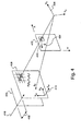
- Fig. 5 illustrates further aspects of a calibration process.
- a first image plane 502, a second image plane 504, and a third image plane 506, such as for a center channel and two side channels of a single lens, three-channel imaging system, or three independent cameras, may acquire disparity information during a lookup table sweep of a calibration target 508, which may be, for example, any of the calibration targets described herein.
- disparity data for one or more points 510 having known camera coordinates may be captured as, for example, x and y coordinates within the processing mesh of one of the image planes (502, 504, 506) and disparity data within the other image planes.
- Each position of the calibration target 508 may more generally yield a field of disparity vectors (or other disparity data) that may be interpolated on a fixed processing mesh. From this data, a lookup table may be generated that locally maps disparity data to depth. In application, the lookup table can be applied to recover parameters for a calculation of calibrated coordinates based on disparity data. In various embodiments, the lookup table may be indexed by location and or value of the disparity data.
- image data including two processing mesh coordinates and a disparity value may be applied as indices to a lookup table that provides camera coordinates for an imaged point.
- image data including two processing mesh coordinates and a disparity value may be applied as indices to a lookup table that provides calibrated indices for a second lookup table.
- the location data may include, for example, a distance from a camera, one or more world coordinates, or one or more camera coordinates for an imaged point.
- a real-time, three-dimensional image capture system that achieves improved accuracy through the use of parameterized lookup tables.
- the above process may be realized in hardware, software, or any combination of these suitable for the three-dimensional imaging techniques described herein.
- the process may be realized in one or more microprocessors, microcontrollers, embedded microcontrollers, programmable digital signal processors or other programmable device, along with internal and/or external memory.
- the process may also, or instead, include an application specific integrated circuit, a programmable gate array, programmable array logic, or any other device that may be configured to process electronic signals.
- the process may be realized as computer executable code created using a structured programming language such as C, an object oriented programming language such as C++, or any other high-level or low-level programming language (including assembly languages, hardware description languages, and database programming languages and technologies) that may be stored, compiled or interpreted to run on one of the above devices, as well as heterogeneous combinations of processors, processor architectures, or combinations of different hardware and software.
- processing may be distributed across the camera and/or computer in a number of ways, or all of the functionality may be integrated into a dedicated, standalone image capture device. All such permutations and combinations are intended to fall within the scope of the present disclosure.
Applications Claiming Priority (5)
| Application Number | Priority Date | Filing Date | Title |
|---|---|---|---|
| US72023805P | 2005-09-22 | 2005-09-22 | |
| US76090206P | 2006-01-20 | 2006-01-20 | |
| US77564306P | 2006-02-22 | 2006-02-22 | |
| EP20110183563 EP2439697A3 (de) | 2005-09-22 | 2006-09-22 | Verfahren zur Verfeingerung der Kalibrierung eines Abbildungssystems |
| EP06815235A EP1938246A4 (de) | 2005-09-22 | 2006-09-22 | Artefakt-verminderung bei der dreidimensionalen abbildung |
Related Parent Applications (2)
| Application Number | Title | Priority Date | Filing Date |
|---|---|---|---|
| EP06815235A Division EP1938246A4 (de) | 2005-09-22 | 2006-09-22 | Artefakt-verminderung bei der dreidimensionalen abbildung |
| EP20110183563 Division EP2439697A3 (de) | 2005-09-22 | 2006-09-22 | Verfahren zur Verfeingerung der Kalibrierung eines Abbildungssystems |
Publications (1)
| Publication Number | Publication Date |
|---|---|
| EP3007131A1 true EP3007131A1 (de) | 2016-04-13 |
Family
ID=37900328
Family Applications (3)
| Application Number | Title | Priority Date | Filing Date |
|---|---|---|---|
| EP20110183563 Withdrawn EP2439697A3 (de) | 2005-09-22 | 2006-09-22 | Verfahren zur Verfeingerung der Kalibrierung eines Abbildungssystems |
| EP06815235A Withdrawn EP1938246A4 (de) | 2005-09-22 | 2006-09-22 | Artefakt-verminderung bei der dreidimensionalen abbildung |
| EP15177700.0A Withdrawn EP3007131A1 (de) | 2005-09-22 | 2006-09-22 | Verfahren zum raffinieren der kalibrierung eines abbildungssystems |
Family Applications Before (2)
| Application Number | Title | Priority Date | Filing Date |
|---|---|---|---|
| EP20110183563 Withdrawn EP2439697A3 (de) | 2005-09-22 | 2006-09-22 | Verfahren zur Verfeingerung der Kalibrierung eines Abbildungssystems |
| EP06815235A Withdrawn EP1938246A4 (de) | 2005-09-22 | 2006-09-22 | Artefakt-verminderung bei der dreidimensionalen abbildung |
Country Status (8)
| Country | Link |
|---|---|
| US (1) | US7742635B2 (de) |
| EP (3) | EP2439697A3 (de) |
| JP (1) | JP2009509582A (de) |
| KR (1) | KR20080051184A (de) |
| CN (1) | CN101292255B (de) |
| AU (1) | AU2006295455A1 (de) |
| CA (1) | CA2623053A1 (de) |
| WO (1) | WO2007038330A2 (de) |
Families Citing this family (64)
| Publication number | Priority date | Publication date | Assignee | Title |
|---|---|---|---|---|
| JP2009509582A (ja) | 2005-09-22 | 2009-03-12 | スリーエム イノベイティブ プロパティズ カンパニー | 3次元イメージングにおけるアーチファクトの軽減 |
| US20090305185A1 (en) * | 2008-05-05 | 2009-12-10 | Lauren Mark D | Method Of Designing Custom Articulator Inserts Using Four-Dimensional Data |
| US8794962B2 (en) | 2006-03-03 | 2014-08-05 | 4D Dental Systems, Inc. | Methods and composition for tracking jaw motion |
| WO2008036354A1 (en) | 2006-09-19 | 2008-03-27 | Braintech Canada, Inc. | System and method of determining object pose |
| US20080181485A1 (en) * | 2006-12-15 | 2008-07-31 | Beis Jeffrey S | System and method of identifying objects |
| CN100580370C (zh) * | 2007-05-30 | 2010-01-13 | 北京航空航天大学 | 基于双面靶标的流动式三维视觉测量拼接方法 |
| US7957583B2 (en) * | 2007-08-02 | 2011-06-07 | Roboticvisiontech Llc | System and method of three-dimensional pose estimation |
| US8847922B1 (en) * | 2007-09-04 | 2014-09-30 | Imaging Systems Technology, Inc. | Calibrating of interactive touch system for image compositing |
| US8840558B2 (en) * | 2008-06-05 | 2014-09-23 | Starkey Laboratories, Inc. | Method and apparatus for mathematically characterizing ear canal geometry |
| DE102008002730B4 (de) * | 2008-06-27 | 2021-09-16 | Robert Bosch Gmbh | Verfahren und Vorrichtung zur 3D-Rekonstruktion |
| DE102008002725B4 (de) * | 2008-06-27 | 2013-11-07 | Robert Bosch Gmbh | Verfahren und Vorrichtung zur 3D-Rekonstruktion |
| US8300089B2 (en) * | 2008-08-14 | 2012-10-30 | Reald Inc. | Stereoscopic depth mapping |
| US9251621B2 (en) * | 2008-08-14 | 2016-02-02 | Reald Inc. | Point reposition depth mapping |
| EP2340534B1 (de) * | 2008-10-03 | 2013-07-24 | RealD Inc. | Optimaltiefenabbildung |
| US8559699B2 (en) * | 2008-10-10 | 2013-10-15 | Roboticvisiontech Llc | Methods and apparatus to facilitate operations in image based systems |
| US9734419B1 (en) * | 2008-12-30 | 2017-08-15 | Cognex Corporation | System and method for validating camera calibration in a vision system |
| KR20100081881A (ko) * | 2009-01-07 | 2010-07-15 | 삼성전자주식회사 | 데이터 매칭 장치, 데이터 매칭 방법, 및 이를 이용한 이동로봇 |
| US20100268069A1 (en) * | 2009-04-16 | 2010-10-21 | Rongguang Liang | Dental surface imaging using polarized fringe projection |
| DK2258266T3 (da) | 2009-06-05 | 2012-07-09 | Starkey Lab Inc | Fremgangsmåde og apparat til matematisk karakterisering af ørekanalens geometri |
| MX2012002948A (es) | 2009-09-11 | 2012-07-17 | Disney Entpr Inc | Inserciones virtuales en video 3d. |
| JP2011188083A (ja) * | 2010-03-05 | 2011-09-22 | Sony Corp | 情報処理装置、情報処理方法、プログラム、及び光学顕微鏡を搭載した撮像装置 |
| US9393694B2 (en) | 2010-05-14 | 2016-07-19 | Cognex Corporation | System and method for robust calibration between a machine vision system and a robot |
| DE102010024666A1 (de) * | 2010-06-18 | 2011-12-22 | Hella Kgaa Hueck & Co. | Verfahren zur optischen Selbstdiagnose eines Kamerasystems und Vorrichtung zur Durchführung eines solchen Verfahrens |
| FR2972061B1 (fr) * | 2011-02-24 | 2013-11-15 | Mobiclip | Procede de calibrage d'un dispositif de prise de vue stereoscopique |
| US8900126B2 (en) | 2011-03-23 | 2014-12-02 | United Sciences, Llc | Optical scanning device |
| US9602801B2 (en) * | 2011-07-18 | 2017-03-21 | Truality, Llc | Method for smoothing transitions between scenes of a stereo film and controlling or regulating a plurality of 3D cameras |
| KR20130015146A (ko) * | 2011-08-02 | 2013-02-13 | 삼성전자주식회사 | 의료 영상 처리 방법 및 장치, 영상 유도를 이용한 로봇 수술 시스템 |
| DE102011109301B4 (de) | 2011-08-03 | 2013-05-08 | 3Ality Digital Systems, Llc | Verfahren zum Korrigieren der Zoom-Einstellung und/oder des vertikalen Versatzes von Teilbildern eines Stereofilms sowie Steuerung oder Regelung eines Kamerarigs mit zwei Kameras |
| WO2013103410A1 (en) | 2012-01-05 | 2013-07-11 | California Institute Of Technology | Imaging surround systems for touch-free display control |
| US8900125B2 (en) | 2012-03-12 | 2014-12-02 | United Sciences, Llc | Otoscanning with 3D modeling |
| WO2013158097A1 (en) * | 2012-04-19 | 2013-10-24 | Intel Corporation | 3d video coding including depth based disparity vector calibration |
| DE102012209316A1 (de) * | 2012-06-01 | 2013-12-05 | Robert Bosch Gmbh | Verfahren und Vorrichtung zum Verarbeiten von Sensordaten eines Stereosensorsystems |
| US20140018994A1 (en) * | 2012-07-13 | 2014-01-16 | Thomas A. Panzarella | Drive-Control Systems for Vehicles Such as Personal-Transportation Vehicles |
| WO2014052824A1 (en) * | 2012-09-27 | 2014-04-03 | Vangogh Imaging Inc. | 3d vision processing |
| US9530213B2 (en) | 2013-01-02 | 2016-12-27 | California Institute Of Technology | Single-sensor system for extracting depth information from image blur |
| CN104079941B (zh) * | 2013-03-27 | 2017-08-25 | 中兴通讯股份有限公司 | 一种深度信息编解码方法、装置及视频处理播放设备 |
| US9183635B2 (en) * | 2013-05-20 | 2015-11-10 | Mitsubishi Electric Research Laboratories, Inc. | Method for reconstructing 3D lines from 2D lines in an image |
| US9715761B2 (en) | 2013-07-08 | 2017-07-25 | Vangogh Imaging, Inc. | Real-time 3D computer vision processing engine for object recognition, reconstruction, and analysis |
| US9675419B2 (en) | 2013-08-21 | 2017-06-13 | Brachium, Inc. | System and method for automating medical procedures |
| KR101510312B1 (ko) * | 2013-09-13 | 2015-04-10 | 인하대학교 산학협력단 | 복수의 카메라들을 이용한 3d 얼굴 모델링 장치, 시스템 및 방법 |
| US10062180B2 (en) * | 2014-04-22 | 2018-08-28 | Microsoft Technology Licensing, Llc | Depth sensor calibration and per-pixel correction |
| CN104065947B (zh) * | 2014-06-18 | 2016-06-01 | 长春理工大学 | 一种集成成像系统的深度图获取方法 |
| US9888229B2 (en) * | 2014-06-23 | 2018-02-06 | Ricoh Company, Ltd. | Disparity estimation for multiview imaging systems |
| US10321126B2 (en) * | 2014-07-08 | 2019-06-11 | Zspace, Inc. | User input device camera |
| US9675430B2 (en) | 2014-08-15 | 2017-06-13 | Align Technology, Inc. | Confocal imaging apparatus with curved focal surface |
| US9710960B2 (en) | 2014-12-04 | 2017-07-18 | Vangogh Imaging, Inc. | Closed-form 3D model generation of non-rigid complex objects from incomplete and noisy scans |
| US9940717B2 (en) * | 2014-12-23 | 2018-04-10 | Intel Corporation | Method and system of geometric camera self-calibration quality assessment |
| US20160191901A1 (en) | 2014-12-24 | 2016-06-30 | 3M Innovative Properties Company | 3d image capture apparatus with cover window fiducials for calibration |
| US10742961B2 (en) * | 2015-09-02 | 2020-08-11 | Industrial Technology Research Institute | Depth sensing apparatus with self-calibration and self-calibration method thereof |
| US10451407B2 (en) * | 2015-11-23 | 2019-10-22 | The Boeing Company | System and method of analyzing a curved surface |
| US10321114B2 (en) * | 2016-08-04 | 2019-06-11 | Google Llc | Testing 3D imaging systems |
| US10380762B2 (en) | 2016-10-07 | 2019-08-13 | Vangogh Imaging, Inc. | Real-time remote collaboration and virtual presence using simultaneous localization and mapping to construct a 3D model and update a scene based on sparse data |
| US10777018B2 (en) * | 2017-05-17 | 2020-09-15 | Bespoke, Inc. | Systems and methods for determining the scale of human anatomy from images |
| US9940535B1 (en) * | 2017-09-07 | 2018-04-10 | Symbol Technologies, Llc | Imaging-based sensor calibration |
| US10839585B2 (en) | 2018-01-05 | 2020-11-17 | Vangogh Imaging, Inc. | 4D hologram: real-time remote avatar creation and animation control |
| US11154375B2 (en) | 2018-02-02 | 2021-10-26 | Brachium, Inc. | Medical robotic work station |
| US11080540B2 (en) | 2018-03-20 | 2021-08-03 | Vangogh Imaging, Inc. | 3D vision processing using an IP block |
| US10810783B2 (en) | 2018-04-03 | 2020-10-20 | Vangogh Imaging, Inc. | Dynamic real-time texture alignment for 3D models |
| US11170224B2 (en) | 2018-05-25 | 2021-11-09 | Vangogh Imaging, Inc. | Keyframe-based object scanning and tracking |
| KR20200005332A (ko) * | 2018-07-06 | 2020-01-15 | 삼성전자주식회사 | 캘리브레이션 장치 및 그것의 동작 방법 |
| US10628989B2 (en) * | 2018-07-16 | 2020-04-21 | Electronic Arts Inc. | Photometric image processing |
| US11232633B2 (en) | 2019-05-06 | 2022-01-25 | Vangogh Imaging, Inc. | 3D object capture and object reconstruction using edge cloud computing resources |
| US11170552B2 (en) | 2019-05-06 | 2021-11-09 | Vangogh Imaging, Inc. | Remote visualization of three-dimensional (3D) animation with synchronized voice in real-time |
| US11335063B2 (en) | 2020-01-03 | 2022-05-17 | Vangogh Imaging, Inc. | Multiple maps for 3D object scanning and reconstruction |
Citations (1)
| Publication number | Priority date | Publication date | Assignee | Title |
|---|---|---|---|---|
| US20040155975A1 (en) | 2002-09-17 | 2004-08-12 | Hart Douglas P. | 3-D imaging system |
Family Cites Families (15)
| Publication number | Priority date | Publication date | Assignee | Title |
|---|---|---|---|---|
| US5085502A (en) * | 1987-04-30 | 1992-02-04 | Eastman Kodak Company | Method and apparatus for digital morie profilometry calibrated for accurate conversion of phase information into distance measurements in a plurality of directions |
| US5159361A (en) * | 1989-03-09 | 1992-10-27 | Par Technology Corporation | Method and apparatus for obtaining the topography of an object |
| US7068825B2 (en) | 1999-03-08 | 2006-06-27 | Orametrix, Inc. | Scanning system and calibration method for capturing precise three-dimensional information of objects |
| US6199024B1 (en) * | 1999-09-07 | 2001-03-06 | Nextel Ltd. | Calibration process for shape measurement |
| AU1486101A (en) * | 1999-11-12 | 2001-06-06 | Brian S. Armstrong | Image metrology methods and apparatus |
| US7362969B2 (en) * | 2001-05-29 | 2008-04-22 | Lucent Technologies Inc. | Camera model and calibration procedure for omnidirectional paraboloidal catadioptric cameras |
| WO2003012368A1 (fr) * | 2001-07-30 | 2003-02-13 | Topcon Corporation | Appareil de mesure d'une forme superficielle, procede de mesure d'une forme superficielle et appareil graphique destine a l'etat superficiel |
| JP4021685B2 (ja) * | 2002-03-04 | 2007-12-12 | 松下電器産業株式会社 | 画像合成変換装置 |
| US7373270B2 (en) * | 2003-03-26 | 2008-05-13 | Sony Corporation | Diagnosing device for stereo camera mounted on robot, and diagnostic method of stereo camera mounted on robot apparatus |
| US7623250B2 (en) * | 2005-02-04 | 2009-11-24 | Stryker Leibinger Gmbh & Co. Kg. | Enhanced shape characterization device and method |
| US7583815B2 (en) * | 2005-04-05 | 2009-09-01 | Objectvideo Inc. | Wide-area site-based video surveillance system |
| EP1889171A4 (de) * | 2005-04-07 | 2012-11-28 | Visionsense Ltd | Verfahren zum rekonstruieren einer dreidimensionalen oberfläche eines objekts |
| JP2009509582A (ja) | 2005-09-22 | 2009-03-12 | スリーエム イノベイティブ プロパティズ カンパニー | 3次元イメージングにおけるアーチファクトの軽減 |
| US20070167702A1 (en) * | 2005-12-30 | 2007-07-19 | Intuitive Surgical Inc. | Medical robotic system providing three-dimensional telestration |
| US7742624B2 (en) * | 2006-04-25 | 2010-06-22 | Motorola, Inc. | Perspective improvement for image and video applications |
-
2006
- 2006-09-22 JP JP2008532440A patent/JP2009509582A/ja not_active Withdrawn
- 2006-09-22 AU AU2006295455A patent/AU2006295455A1/en not_active Abandoned
- 2006-09-22 EP EP20110183563 patent/EP2439697A3/de not_active Withdrawn
- 2006-09-22 US US11/534,570 patent/US7742635B2/en not_active Expired - Fee Related
- 2006-09-22 WO PCT/US2006/037089 patent/WO2007038330A2/en active Application Filing
- 2006-09-22 CN CN2006800393945A patent/CN101292255B/zh not_active Expired - Fee Related
- 2006-09-22 EP EP06815235A patent/EP1938246A4/de not_active Withdrawn
- 2006-09-22 KR KR1020087009564A patent/KR20080051184A/ko not_active Application Discontinuation
- 2006-09-22 CA CA002623053A patent/CA2623053A1/en not_active Abandoned
- 2006-09-22 EP EP15177700.0A patent/EP3007131A1/de not_active Withdrawn
Patent Citations (1)
| Publication number | Priority date | Publication date | Assignee | Title |
|---|---|---|---|---|
| US20040155975A1 (en) | 2002-09-17 | 2004-08-12 | Hart Douglas P. | 3-D imaging system |
Non-Patent Citations (4)
| Title |
|---|
| AGRAWAL ET AL: "Camera calibration using spheres: a semi-definite programming approach", PROCEEDINGS OF THE EIGHT IEEE INTERNATIONAL CONFERENCE ON COMPUTER VISION. (ICCV). NICE, FRANCE, OCT. 13 - 16, 2003; [INTERNATIONAL CONFERENCE ON COMPUTER VISION], LOS ALAMITOS, CA : IEEE COMP. SOC, US, 13 October 2003 (2003-10-13), pages 1 - 8, XP031213127, ISBN: 978-0-7695-1950-0 * |
| JUYANG WENG ET AL: "CAMERA CALIBRATION WITH DISTORTION MODELS AND ACCURACY EVALUATION", IEEE TRANSACTIONS ON PATTERN ANALYSIS AND MACHINE INTELLIGENCE, IEEE COMPUTER SOCIETY, USA, vol. 14, no. 10, 1 October 1992 (1992-10-01), pages 965 - 980, XP000328810, ISSN: 0162-8828, DOI: 10.1109/34.159901 * |
| KATSUSHI IKEUCHI: "Determining a depth map from a pair of needle maps by a pair of photometric stereo systems with region matching", SYSTEMS & COMPUTERS IN JAPAN., vol. 17, no. 5, 1 January 1986 (1986-01-01), US, pages 92 - 103, XP055254354, ISSN: 0882-1666, DOI: 10.1002/scj.4690170511 * |
| QUINN Y. J. SMITHWICK ET AL: "Depth enhancement using a scanning fiber optical endoscope", MEDICAL IMAGING 2002: PACS AND INTEGRATED MEDICAL INFORMATION SYSTEMS: DESIGN AND EVALUATION, vol. 4613, 1 May 2002 (2002-05-01), 1000 20th St. Bellingham WA 98225-6705 USA, pages 222 - 233, XP055254344, ISSN: 0277-786X, ISBN: 978-1-5106-0167-3, DOI: 10.1117/12.465249 * |
Also Published As
| Publication number | Publication date |
|---|---|
| KR20080051184A (ko) | 2008-06-10 |
| WO2007038330A3 (en) | 2008-01-17 |
| WO2007038330A2 (en) | 2007-04-05 |
| JP2009509582A (ja) | 2009-03-12 |
| AU2006295455A1 (en) | 2007-04-05 |
| US20070075997A1 (en) | 2007-04-05 |
| EP1938246A4 (de) | 2011-04-06 |
| US7742635B2 (en) | 2010-06-22 |
| EP2439697A3 (de) | 2012-07-04 |
| EP2439697A2 (de) | 2012-04-11 |
| EP1938246A2 (de) | 2008-07-02 |
| CN101292255B (zh) | 2012-05-23 |
| CA2623053A1 (en) | 2007-04-05 |
| CN101292255A (zh) | 2008-10-22 |
Similar Documents
| Publication | Publication Date | Title |
|---|---|---|
| US7742635B2 (en) | Artifact mitigation in three-dimensional imaging | |
| US9191648B2 (en) | Hybrid stitching | |
| US9544577B2 (en) | Method of capturing three-dimensional (3D) information on a structure | |
| US9563954B2 (en) | Method for capturing the three-dimensional surface geometry of objects | |
| US8803958B2 (en) | Global camera path optimization | |
| WO2021140886A1 (ja) | 三次元モデル生成方法、情報処理装置およびプログラム | |
| CN110390719A (zh) | 基于飞行时间点云重建设备 | |
| JP2009017480A (ja) | カメラキャリブレーション装置およびそのプログラム | |
| US10552984B2 (en) | Capture device calibration methods and systems | |
| JP2009512049A (ja) | 画像処理方法および装置 | |
| WO2015054285A1 (en) | Integrated calibration cradle | |
| JP2019530059A (ja) | 複数の対象とする領域を独立的に処理する方法 | |
| WO2009120073A2 (en) | A dynamically calibrated self referenced three dimensional structured light scanner | |
| WO2017214735A1 (en) | Systems and methods for obtaining a structured light reconstruction of a 3d surface | |
| Silvester et al. | A critical assessment of the potential for structure‐from‐motion photogrammetry to produce high fidelity 3D dental models | |
| JP6614905B2 (ja) | 三次元計測装置およびその制御方法 | |
| JP2007508557A (ja) | 三次元物体を走査するための装置 | |
| JPWO2020075252A1 (ja) | 情報処理装置、プログラム及び情報処理方法 | |
| CN1544883A (zh) | 基于特定网格图案的三维脚型测量和建模的方法 | |
| Rothbucher et al. | Measuring anthropometric data for HRTF personalization | |
| US8121389B2 (en) | System, apparatus, method and computer program product for optical position recognition | |
| JP2022064313A (ja) | 三次元の歯科構造のカラー画像の比較 | |
| KR101775110B1 (ko) | 고품질 텍스처 획득 방법 및 이를 위한 장치 | |
| Lacher | 3D breast surface reconstructions from consumer-grade RGB-D cameras | |
| Hemmati et al. | A study on the refractive effect of glass in vision systems |
Legal Events
| Date | Code | Title | Description |
|---|---|---|---|
| PUAI | Public reference made under article 153(3) epc to a published international application that has entered the european phase |
Free format text: ORIGINAL CODE: 0009012 |
|
| AC | Divisional application: reference to earlier application |
Ref document number: 2439697 Country of ref document: EP Kind code of ref document: P Ref document number: 1938246 Country of ref document: EP Kind code of ref document: P |
|
| AK | Designated contracting states |
Kind code of ref document: A1 Designated state(s): AT BE BG CH CY CZ DE DK EE ES FI FR GB GR HU IE IS IT LI LT LU LV MC NL PL PT RO SE SI SK TR |
|
| 17P | Request for examination filed |
Effective date: 20161013 |
|
| RBV | Designated contracting states (corrected) |
Designated state(s): AT BE BG CH CY CZ DE DK EE ES FI FR GB GR HU IE IS IT LI LT LU LV MC NL PL PT RO SE SI SK TR |
|
| STAA | Information on the status of an ep patent application or granted ep patent |
Free format text: STATUS: EXAMINATION IS IN PROGRESS |
|
| 17Q | First examination report despatched |
Effective date: 20170404 |
|
| STAA | Information on the status of an ep patent application or granted ep patent |
Free format text: STATUS: THE APPLICATION IS DEEMED TO BE WITHDRAWN |
|
| 18D | Application deemed to be withdrawn |
Effective date: 20190402 |