EP3007015A1 - Ensemble d'affichage hybride comprenant une cellule solaire - Google Patents
Ensemble d'affichage hybride comprenant une cellule solaire Download PDFInfo
- Publication number
- EP3007015A1 EP3007015A1 EP15177931.1A EP15177931A EP3007015A1 EP 3007015 A1 EP3007015 A1 EP 3007015A1 EP 15177931 A EP15177931 A EP 15177931A EP 3007015 A1 EP3007015 A1 EP 3007015A1
- Authority
- EP
- European Patent Office
- Prior art keywords
- display
- transparent
- reflective
- liquid crystal
- cell
- Prior art date
- Legal status (The legal status is an assumption and is not a legal conclusion. Google has not performed a legal analysis and makes no representation as to the accuracy of the status listed.)
- Granted
Links
Images


Classifications
-
- H—ELECTRICITY
- H10—SEMICONDUCTOR DEVICES; ELECTRIC SOLID-STATE DEVICES NOT OTHERWISE PROVIDED FOR
- H10K—ORGANIC ELECTRIC SOLID-STATE DEVICES
- H10K59/00—Integrated devices, or assemblies of multiple devices, comprising at least one organic light-emitting element covered by group H10K50/00
- H10K59/60—OLEDs integrated with inorganic light-sensitive elements, e.g. with inorganic solar cells or inorganic photodiodes
-
- G—PHYSICS
- G02—OPTICS
- G02F—OPTICAL DEVICES OR ARRANGEMENTS FOR THE CONTROL OF LIGHT BY MODIFICATION OF THE OPTICAL PROPERTIES OF THE MEDIA OF THE ELEMENTS INVOLVED THEREIN; NON-LINEAR OPTICS; FREQUENCY-CHANGING OF LIGHT; OPTICAL LOGIC ELEMENTS; OPTICAL ANALOGUE/DIGITAL CONVERTERS
- G02F1/00—Devices or arrangements for the control of the intensity, colour, phase, polarisation or direction of light arriving from an independent light source, e.g. switching, gating or modulating; Non-linear optics
- G02F1/01—Devices or arrangements for the control of the intensity, colour, phase, polarisation or direction of light arriving from an independent light source, e.g. switching, gating or modulating; Non-linear optics for the control of the intensity, phase, polarisation or colour
- G02F1/13—Devices or arrangements for the control of the intensity, colour, phase, polarisation or direction of light arriving from an independent light source, e.g. switching, gating or modulating; Non-linear optics for the control of the intensity, phase, polarisation or colour based on liquid crystals, e.g. single liquid crystal display cells
- G02F1/133—Constructional arrangements; Operation of liquid crystal cells; Circuit arrangements
- G02F1/1333—Constructional arrangements; Manufacturing methods
- G02F1/1335—Structural association of cells with optical devices, e.g. polarisers or reflectors
- G02F1/133553—Reflecting elements
- G02F1/133555—Transflectors
-
- G—PHYSICS
- G02—OPTICS
- G02F—OPTICAL DEVICES OR ARRANGEMENTS FOR THE CONTROL OF LIGHT BY MODIFICATION OF THE OPTICAL PROPERTIES OF THE MEDIA OF THE ELEMENTS INVOLVED THEREIN; NON-LINEAR OPTICS; FREQUENCY-CHANGING OF LIGHT; OPTICAL LOGIC ELEMENTS; OPTICAL ANALOGUE/DIGITAL CONVERTERS
- G02F1/00—Devices or arrangements for the control of the intensity, colour, phase, polarisation or direction of light arriving from an independent light source, e.g. switching, gating or modulating; Non-linear optics
- G02F1/01—Devices or arrangements for the control of the intensity, colour, phase, polarisation or direction of light arriving from an independent light source, e.g. switching, gating or modulating; Non-linear optics for the control of the intensity, phase, polarisation or colour
- G02F1/13—Devices or arrangements for the control of the intensity, colour, phase, polarisation or direction of light arriving from an independent light source, e.g. switching, gating or modulating; Non-linear optics for the control of the intensity, phase, polarisation or colour based on liquid crystals, e.g. single liquid crystal display cells
- G02F1/133—Constructional arrangements; Operation of liquid crystal cells; Circuit arrangements
- G02F1/13306—Circuit arrangements or driving methods for the control of single liquid crystal cells
-
- G—PHYSICS
- G02—OPTICS
- G02F—OPTICAL DEVICES OR ARRANGEMENTS FOR THE CONTROL OF LIGHT BY MODIFICATION OF THE OPTICAL PROPERTIES OF THE MEDIA OF THE ELEMENTS INVOLVED THEREIN; NON-LINEAR OPTICS; FREQUENCY-CHANGING OF LIGHT; OPTICAL LOGIC ELEMENTS; OPTICAL ANALOGUE/DIGITAL CONVERTERS
- G02F1/00—Devices or arrangements for the control of the intensity, colour, phase, polarisation or direction of light arriving from an independent light source, e.g. switching, gating or modulating; Non-linear optics
- G02F1/01—Devices or arrangements for the control of the intensity, colour, phase, polarisation or direction of light arriving from an independent light source, e.g. switching, gating or modulating; Non-linear optics for the control of the intensity, phase, polarisation or colour
- G02F1/13—Devices or arrangements for the control of the intensity, colour, phase, polarisation or direction of light arriving from an independent light source, e.g. switching, gating or modulating; Non-linear optics for the control of the intensity, phase, polarisation or colour based on liquid crystals, e.g. single liquid crystal display cells
- G02F1/133—Constructional arrangements; Operation of liquid crystal cells; Circuit arrangements
- G02F1/1333—Constructional arrangements; Manufacturing methods
- G02F1/1335—Structural association of cells with optical devices, e.g. polarisers or reflectors
- G02F1/13363—Birefringent elements, e.g. for optical compensation
-
- H—ELECTRICITY
- H10—SEMICONDUCTOR DEVICES; ELECTRIC SOLID-STATE DEVICES NOT OTHERWISE PROVIDED FOR
- H10K—ORGANIC ELECTRIC SOLID-STATE DEVICES
- H10K59/00—Integrated devices, or assemblies of multiple devices, comprising at least one organic light-emitting element covered by group H10K50/00
- H10K59/50—OLEDs integrated with light modulating elements, e.g. with electrochromic elements, photochromic elements or liquid crystal elements
-
- G—PHYSICS
- G02—OPTICS
- G02F—OPTICAL DEVICES OR ARRANGEMENTS FOR THE CONTROL OF LIGHT BY MODIFICATION OF THE OPTICAL PROPERTIES OF THE MEDIA OF THE ELEMENTS INVOLVED THEREIN; NON-LINEAR OPTICS; FREQUENCY-CHANGING OF LIGHT; OPTICAL LOGIC ELEMENTS; OPTICAL ANALOGUE/DIGITAL CONVERTERS
- G02F1/00—Devices or arrangements for the control of the intensity, colour, phase, polarisation or direction of light arriving from an independent light source, e.g. switching, gating or modulating; Non-linear optics
- G02F1/01—Devices or arrangements for the control of the intensity, colour, phase, polarisation or direction of light arriving from an independent light source, e.g. switching, gating or modulating; Non-linear optics for the control of the intensity, phase, polarisation or colour
- G02F1/13—Devices or arrangements for the control of the intensity, colour, phase, polarisation or direction of light arriving from an independent light source, e.g. switching, gating or modulating; Non-linear optics for the control of the intensity, phase, polarisation or colour based on liquid crystals, e.g. single liquid crystal display cells
- G02F1/133—Constructional arrangements; Operation of liquid crystal cells; Circuit arrangements
- G02F1/13306—Circuit arrangements or driving methods for the control of single liquid crystal cells
- G02F1/13324—Circuits comprising solar cells
-
- G—PHYSICS
- G02—OPTICS
- G02F—OPTICAL DEVICES OR ARRANGEMENTS FOR THE CONTROL OF LIGHT BY MODIFICATION OF THE OPTICAL PROPERTIES OF THE MEDIA OF THE ELEMENTS INVOLVED THEREIN; NON-LINEAR OPTICS; FREQUENCY-CHANGING OF LIGHT; OPTICAL LOGIC ELEMENTS; OPTICAL ANALOGUE/DIGITAL CONVERTERS
- G02F1/00—Devices or arrangements for the control of the intensity, colour, phase, polarisation or direction of light arriving from an independent light source, e.g. switching, gating or modulating; Non-linear optics
- G02F1/01—Devices or arrangements for the control of the intensity, colour, phase, polarisation or direction of light arriving from an independent light source, e.g. switching, gating or modulating; Non-linear optics for the control of the intensity, phase, polarisation or colour
- G02F1/13—Devices or arrangements for the control of the intensity, colour, phase, polarisation or direction of light arriving from an independent light source, e.g. switching, gating or modulating; Non-linear optics for the control of the intensity, phase, polarisation or colour based on liquid crystals, e.g. single liquid crystal display cells
- G02F1/133—Constructional arrangements; Operation of liquid crystal cells; Circuit arrangements
- G02F1/1333—Constructional arrangements; Manufacturing methods
- G02F1/1335—Structural association of cells with optical devices, e.g. polarisers or reflectors
- G02F1/133528—Polarisers
- G02F1/133536—Reflective polarizers
-
- G—PHYSICS
- G02—OPTICS
- G02F—OPTICAL DEVICES OR ARRANGEMENTS FOR THE CONTROL OF LIGHT BY MODIFICATION OF THE OPTICAL PROPERTIES OF THE MEDIA OF THE ELEMENTS INVOLVED THEREIN; NON-LINEAR OPTICS; FREQUENCY-CHANGING OF LIGHT; OPTICAL LOGIC ELEMENTS; OPTICAL ANALOGUE/DIGITAL CONVERTERS
- G02F1/00—Devices or arrangements for the control of the intensity, colour, phase, polarisation or direction of light arriving from an independent light source, e.g. switching, gating or modulating; Non-linear optics
- G02F1/01—Devices or arrangements for the control of the intensity, colour, phase, polarisation or direction of light arriving from an independent light source, e.g. switching, gating or modulating; Non-linear optics for the control of the intensity, phase, polarisation or colour
- G02F1/13—Devices or arrangements for the control of the intensity, colour, phase, polarisation or direction of light arriving from an independent light source, e.g. switching, gating or modulating; Non-linear optics for the control of the intensity, phase, polarisation or colour based on liquid crystals, e.g. single liquid crystal display cells
- G02F1/133—Constructional arrangements; Operation of liquid crystal cells; Circuit arrangements
- G02F1/1333—Constructional arrangements; Manufacturing methods
- G02F1/1335—Structural association of cells with optical devices, e.g. polarisers or reflectors
- G02F1/133528—Polarisers
- G02F1/133541—Circular polarisers
-
- G—PHYSICS
- G02—OPTICS
- G02F—OPTICAL DEVICES OR ARRANGEMENTS FOR THE CONTROL OF LIGHT BY MODIFICATION OF THE OPTICAL PROPERTIES OF THE MEDIA OF THE ELEMENTS INVOLVED THEREIN; NON-LINEAR OPTICS; FREQUENCY-CHANGING OF LIGHT; OPTICAL LOGIC ELEMENTS; OPTICAL ANALOGUE/DIGITAL CONVERTERS
- G02F1/00—Devices or arrangements for the control of the intensity, colour, phase, polarisation or direction of light arriving from an independent light source, e.g. switching, gating or modulating; Non-linear optics
- G02F1/01—Devices or arrangements for the control of the intensity, colour, phase, polarisation or direction of light arriving from an independent light source, e.g. switching, gating or modulating; Non-linear optics for the control of the intensity, phase, polarisation or colour
- G02F1/13—Devices or arrangements for the control of the intensity, colour, phase, polarisation or direction of light arriving from an independent light source, e.g. switching, gating or modulating; Non-linear optics for the control of the intensity, phase, polarisation or colour based on liquid crystals, e.g. single liquid crystal display cells
- G02F1/133—Constructional arrangements; Operation of liquid crystal cells; Circuit arrangements
- G02F1/1333—Constructional arrangements; Manufacturing methods
- G02F1/1335—Structural association of cells with optical devices, e.g. polarisers or reflectors
- G02F1/13363—Birefringent elements, e.g. for optical compensation
- G02F1/133638—Waveplates, i.e. plates with a retardation value of lambda/n
-
- G—PHYSICS
- G02—OPTICS
- G02F—OPTICAL DEVICES OR ARRANGEMENTS FOR THE CONTROL OF LIGHT BY MODIFICATION OF THE OPTICAL PROPERTIES OF THE MEDIA OF THE ELEMENTS INVOLVED THEREIN; NON-LINEAR OPTICS; FREQUENCY-CHANGING OF LIGHT; OPTICAL LOGIC ELEMENTS; OPTICAL ANALOGUE/DIGITAL CONVERTERS
- G02F2201/00—Constructional arrangements not provided for in groups G02F1/00 - G02F7/00
- G02F2201/44—Arrangements combining different electro-active layers, e.g. electrochromic, liquid crystal or electroluminescent layers
-
- G—PHYSICS
- G04—HOROLOGY
- G04C—ELECTROMECHANICAL CLOCKS OR WATCHES
- G04C10/00—Arrangements of electric power supplies in time-pieces
- G04C10/02—Arrangements of electric power supplies in time-pieces the power supply being a radioactive or photovoltaic source
Definitions
- the present invention relates to a hybrid display assembly comprising a solar cell. More specifically, the present invention relates to such a display assembly comprising two superimposed display devices in which is arranged a solar cell.
- the readability of the information displayed by display devices is very dependent on ambient light conditions. With some display devices, the information displayed can be read in good conditions in a bright environment, but are difficult to read in a dark environment. Conversely, other categories of display devices provide a good quality display in dim light or dark, but are difficult to read in daylight.
- liquid crystal display cells of transflective type that is to say liquid crystal display cells capable of displaying information that will be visible by day thanks to a phenomenon of reflection, and which will also be visible in the dark by transmission using a backlight device.
- transflective-type liquid crystal display cells are optimized to be able to best reflect the sunlight and thus ensure good readability of the information displayed under conditions of high brightness room.
- transflective liquid crystal display cells can best reflect sunlight, their transmission efficiency is greatly limited.
- the backlighting device is activated in order to read the information displayed in the penumbra, a major part of the light emitted by the backlighting device is lost in absorption phenomena. The energy efficiency is therefore poor.
- the optical qualities of the information displayed by the liquid crystal cell are strongly dependent on the angle of view.
- the emissive type display devices such as organic electroluminescent diode display devices, they have optical qualities that are superior to those of the liquid crystal display cells, these optical qualities not depending particularly on from the angle of view. Nevertheless, these high quality emissive type display devices do not allow operation in reflective mode. The information they display is therefore very readable in the dark or dark, but become difficult to read as soon as they are observed outdoors. To remedy this problem, it is possible to increase the amount of current supplied to the emissive display devices in order to increase the brightness of the light-emitting diodes and thus guarantee a minimum of readability. However, even under normal use conditions, these emissive display devices consume more than a reflective type liquid crystal cell. Their power consumption is such that it is difficult to envisage keeping them on permanently, especially when they are embedded in a portable object of small dimensions such as a wristwatch whose only source of energy is a battery of which we usually want it to last at least a year.
- the object of the present invention is to remedy the aforementioned problems as well as others by providing a display assembly whose energy requirements can be satisfied even when it is embedded in a portable object of small dimensions such as a wristwatch whose energy reserves are however limited.
- the present invention also provides a display assembly whose operation is satisfactory both in a brightly lit environment and in a dark environment.
- the present invention relates to a display assembly for a portable object, said display assembly comprising a first at least partially transparent emissive display device located on the side of an observer, a second reflective display device. and a solar cell being arranged in this order under the first emissive display, the second reflective display being capable of switching between a transparent state when at rest and a reflective state when activated.
- the transparent emissive display device is fixed on the reflective display device.
- the transparent emissive display device is adhered to the reflective display device by means of a film adhesive or a layer of liquid glue.
- the present invention provides a display assembly for a portable object such as a wristwatch whose operation is optimal regardless of ambient lighting conditions.
- the information will preferably be displayed by the reflective display device.
- this reflective display device taking advantage of a reflection phenomenon of sunlight to display information, is energy efficient. It can therefore remain permanently lit and offers good readability of information.
- the information will be displayed by the emissive display device.
- Such an emissive display device consumes more current than a reflective display device, but the information it displays is visible at night or in the dark with very good optical properties which are in particular independent of the angle of view.
- the display assembly according to the invention proposes to combine two display devices, one purely reflective and the other purely emissive, without compromising the performance of either of these two devices. display.
- the present invention allows the integration of such an assembly in a portable object of small dimensions whose reserves of electrical energy are necessarily limited. Indeed, it has been found that the amount of light that reaches the solar cell through all of the two superimposed display devices is sufficient to provide, by photoelectric conversion phenomenon, the amount of electrical energy required for the operation of the solar cells. two superimposed display devices. Therefore, the electrical energy reserves of the portable object are little, or not solicited by the operation of the two superimposed display devices.
- the first display device comprises a transparent emissive display cell
- the second display device comprises a nematic-type reflective liquid crystal display helical or super-nematic helical or vertical alignment.
- the transparent emissive display cell is optionally an electroluminescent organic diode transparent emissive display cell or an inorganic transparent emissive display cell.
- the electroluminescent organic diode display cell is disposed between a circular polarizer and a quarter-wave plate, the circular polarizer being placed on the side of the observer.
- the present invention teaches arranging the electroluminescent organic diode display cell between a circular polarizer and a quarter wave plate, the circular polarizer being placed on the observer side.
- the circular polarizer being placed on the observer side.
- the circularly polarized ambient light is partially reflected by the transparent electrodes of the organic light emitting diode display cell, this reflected light is phase shifted, which has the effect of transforming its circular polarization into circular polarization of opposite direction of rotation.
- the reflected light crosses again the circular polarizer, it is absorbed by the latter.
- it is possible to eliminate the stray light reflected on the electrodes of the electroluminescent organic diode display cell, and to retain only light passing through the electroluminescent organic diode display cell without modification.
- the light is again linearly polarized after passing through the quarter-wave plate placed beneath the organic electroluminescent diode display cell and will eventually be absorbed or reflected by the reflective liquid crystal display cell according to that one looks for a display with positive or negative contrast.
- the present invention proceeds from the general inventive idea of providing a display assembly that is capable of legibly displaying information both in daylight and in dim light or darkness and whose consumption of electrical energy is optimal.
- the present invention teaches combining an emissive type display device with a display device which is arranged to be able to switch between a state of rest in which it is transparent and an active state in which it is capable of to reflect the ambient light.
- the emissive type display device is typically an organic electroluminescent diode display cell, while the reflective type display device is typically a liquid crystal display cell.
- the reflective type display device In order to display the information in broad daylight, the use of the reflective type display device which, by reflection of the sunlight, allows the information to be displayed in a clear and readable manner while consuming little electrical energy.
- the use of the emissive display device is preferred. Thanks to its excellent optical properties, especially in terms of contrast and color reproduction, such an emissive display device makes it possible to display a large amount of information in a very readable manner. In particular, the readability of the information displayed is not dependent on the angle of view. In addition, in the dark or dark, it is possible to significantly reduce the power consumption of such an emissive display device while ensuring good readability of the information displayed.
- a display assembly which includes a reflective display device placed at the base of the stack and which is capable of displaying information continuously while consuming very little energy, and a display device.
- emissive display placed on the top of the stack and which is able to display information on demand in a very readable way in dim light or darkness. It was further realized that by placing a solar cell under the two superposed display devices, the solar cell produced, by photoelectric conversion effect, an electric current sufficient to allow the operation of the two superimposed display devices. . It is therefore possible to integrate such a display assembly in a portable object of small dimensions such as a wristwatch whose storage capacity in electrical energy are however limited.
- the figure 1 is a schematic sectional view of a display assembly according to the invention.
- this display assembly comprises a first at least partially transparent emitting display device 2 arranged on the side of an observer 4, and a second reflective display device 6 also at the less partially transparent disposed under the first emissive display device 2.
- the first emissive display device 2 is able to switch between a passive state in which is at least partially transparent, and an active state in which it emits light to display information.
- the second reflective display device 6 it is able to switch between a passive state in which it is transparent and an active state in which it is able to reflect the ambient light.
- the first emissive display device 2 is secured to the second reflective display device 6 by means of a transparent adhesive layer 8.
- This transparent adhesive layer 8 may be formed of a film adhesive or a layer of acrylic or silicone liquid glue.
- This transparent adhesive layer 8 is intended to avoid the problems of spurious reflections that would occur if the two display devices 2, 6 were separated by a layer of air and which would degrade the optical quality of the display assembly 1 according to the invention.
- a solar cell 10 capable of supplying electrical energy by exploiting the photoelectric conversion phenomenon is disposed under the second reflective display device 6.
- the solar cell 10 is glued under the second device reflective display 6 by means of a transparent adhesive layer 12.
- the figure 2 is a detailed sectional view of an exemplary embodiment of the display assembly 1 according to the invention in the case where the first emissive display device 2 comprises a display cell transparent emissive 20 organic diode electroluminescent which will be referred to in the following by transparent display cell TOLED (Transparent Organic Light Emitting Diode).
- the second reflective display device 6 it comprises a reflective liquid crystal display cell 60 of helical nematic type, also known by its Anglo-Saxon name Twist Nematic or TN.
- the transparent display unit TOLED 20 comprises a transparent substrate 21 made of glass or a plastic material and an encapsulation cover 22 which extends parallel to and away from the transparent substrate 21.
- the transparent substrate 21 and the encapsulation cover 22 are joined together by a sealing frame 23 which delimits a closed volume protected from air and humidity for the confinement of a stack of electroluminescent layers generally designated by the reference numeral 24.
- a transparent upper electrode 25 made for example of tin-indium oxide or ITO and a transparent lower electrode 26 made for example by means of a metallic material such as aluminum or silver or a metal oxide such as ITO or zinc-indium oxide are structured on either side of the stack of electroluminescent layers 24.
- These electrodes 25, 26, made of a material metallic, are slightly reflective.
- the organic electroluminescent light-emitting diode display cells are available either with direct addressing in cases where it is simply a question of displaying icons or segments, or with a passive matrix type addressing in the case of a dot matrix display. In the case of a dot matrix display, it is also possible to deal with an active matrix type addressing combined with transparent transistors of the Thin Film Transistor or TFT type intended to control the current and which are arranged in the pixels of the matrix. display.
- the reflective liquid crystal display cell 60 comprises a front substrate 61 disposed on the observer's side 4 and a rear substrate 62 which extends parallel to and away from the front substrate 61.
- the front 61 and rear 62 substrates are joined together by a sealing frame 63 which delimits a sealed enclosure 64 for the confinement of a liquid crystal whose Optical properties are modified by applying a suitable voltage at a crossover point considered between transparent electrodes 65a formed on a lower face of the front substrate 61 and transparent counter-electrodes 65b formed on a rear substrate upper face 62.
- 65a and the counter-electrodes 65b are made of a transparent electrically conductive material such as indium-zinc oxide or indium-tin oxide, the latter material being better known by its Anglo-Saxon name Indium Tin Oxide or ITO.
- all the phases of the liquid crystals such as helical nematic (Twist Nematic or TN in English terminology), super-nematic helix (Super Twist Nematic or STN in English terminology) or still vertically aligned (Vertically Aligned or VA in English terminology) can be envisaged.
- all types of addressing such as direct addressing, addressing by active matrix or multiplexed addressing of a passive matrix can be envisaged.
- An absorbent polarizer 30 is adhered to an upper face of the front substrate 61 of the reflective liquid crystal display cell 60 by means of an adhesive layer 32.
- This adhesive layer 32 may be formed from a film adhesive or a layer of liquid glue.
- the adhesive used to secure the absorbing polarizer 30 on the reflective liquid crystal display cell 60 may be transparent or slightly diffusing depending on whether one seeks to obtain specular or diffuse reflection.
- the absorbing polarizer 30 it may be, for example, of the iodine or dye type.
- An absorbent reflective polarizer 34 is adhered to a lower face of the rear substrate 62 of the reflective liquid crystal display cell 60 by means of an adhesive layer 36 which may be transparent or slightly diffusing depending on whether one seeks to obtain specular or diffuse reflection.
- the TOLED transparent display cell 20 and the TN 60 reflective liquid crystal display cell are both turned off.
- the ambient light denoted by the numeral 46
- the ambient light 46 passes through the transparent display cell TOLED 20 without modification, and is then polarized linearly by the absorbing polarizer 30.
- the ambient light 46 is then rotated by 90 ° as it passes through the cell reflective liquid crystal display TN 60, so that when it falls on the reflective polarizer 34, its polarization direction is perpendicular to the reflection axis of the reflective polarizer 34 and therefore crosses the latter before being absorbed by the solar cell 10.
- the reflective liquid crystal display cell TN 60 therefore appears dark when off, which means that the information it will display will appear in the light on a dark background. The display of information is therefore in negative contrast.
- an information display in positive contrast could be achieved simply by ensuring that the transmission axis of the polarizer 30 and the reflection axis of the reflective reflective polarizer 34 are perpendicular. In this case, the ambient light 46 reaches the solar cell only in the areas of the TN reflective liquid crystal display cell 60 that are switched.
- the TOLED transparent display cell 20 is activated, while the TN reflective liquid crystal display cell 60 is turned off.
- the light emitted by the TOLED transparent display cell 20 reaches the observer 4 without modification, while the TN 60 reflective liquid crystal display cell appears dark.
- the information displayed by the transparent display unit TOLED 20 therefore stands out against a dark background.
- the transparent display unit TOLED 20 is off, while the reflective liquid crystal display unit TN 60 is activated.
- the unswitched areas of the TN 60 reflective liquid crystal display cell appear dark.
- the ambient light 46 passes through these zones without modification, so that the ambient light 46 falls on the reflective polarizer 34 with a direction of polarization parallel to the reflection axis of this reflective polarizer 34.
- the ambient light 46 is reflected back and successively passes through the reflective liquid crystal display unit TN 60, the absorbing polarizer 30 and the transparent display cell TOLED 20 unchanged , so that it is perceptible by the observer 4.
- the information is displayed in clear on a dark background.
- the TOLED transparent display cell 20 and the TN 60 reflective liquid crystal display cell are both activated.
- the light emitted by the transparent display unit TOLED 20 is directly perceptible by the observer 4.
- the ambient light 46 which passes through the unswitched areas of the TN 60 reflective liquid crystal display cell is absorbed by the solar cell 10 , so these areas appear dark.
- the ambient light 46 which passes through the switched areas of the TN 60 reflective liquid crystal display cell is reflected by the reflective polarizer 34, so that these areas appear clear.
- the figure 4 is a sectional view of an exemplary embodiment of the display assembly 1 according to the invention in the case where the first display device 2 comprises a transparent emissive display cell 20 with organic electroluminescent diodes which will be designated in all that follows by transparent display cell TOLED (Transparent Organic Light Emitting Diode).
- the second display device 6 it comprises a reflective liquid crystal display 600 vertically aligned, also known by its Anglo-Saxon Vertically Aligned or VA.
- the TOLED transparent display cell 20 and the VA 600 reflective liquid crystal display cell are both turned off.
- the ambient light denoted by the numeral 46, passes successively through the transparent display unit TOLED 20 and the reflective liquid crystal display unit VA 600, so that when it falls on the reflective polarizer 34, its polarization direction is perpendicular to the axis of reflection of the reflective polarizer 34. It crosses the latter without modification and is ultimately absorbed by the solar cell 10.
- the reflective liquid crystal display unit VA 600 appears dark when it is off, which means that the information it will display will appear in the clear on a dark background.
- the display of information is therefore in negative contrast.
- a display of the information in a positive contrast can be obtained simply by ensuring that the transmission axis of the absorbing polarizer 30 and the reflection axis of the reflective polarizer 34 are parallel.
- the transparent display unit TOLED 20 is activated, while the reflective liquid crystal display unit VA 600 is deactivated.
- the light emitted by the transparent display unit TOLED 20 reaches the observer 4 without modification, while the reflective liquid crystal display unit VA 600 appears dark.
- the information displayed by the transparent display unit TOLED 20 therefore stands out against a dark background.
- the transparent display unit TOLED 20 is off, while the reflective liquid crystal display unit VA 600 is activated.
- the alignment layers are oriented at 45 ° with respect to the polarization axes of the polarizers.
- the product result between the birefringence of the liquid crystal molecules and the distance between the front and back substrates is chosen so that, when the liquid crystal is switched, it behaves vis-à-vis the direction polarization of light as a half-wave plate. Therefore, since this half-wave plate is placed at 45 ° with respect to the polarization axis of the absorbing polarizer, it causes a 90 ° rotation of the polarization direction of the light.
- the ambient light 46 is rotated by 90 ° as it passes through the switched areas of the VA 600 reflective liquid crystal display cell, so that when it falls on the reflective polarizer 34, its polarization direction is parallel to the reflection axis of the reflective polarizer 34 and is therefore reflected by the latter.
- the ambient light 46 which passes through the unswitched zones of the reflective liquid crystal display unit VA 600 it is absorbed by the solar cell 10.
- the information is displayed in clear on a dark background, it is to say with a negative contrast.
- the TOLED transparent display cell 20 and the VA 600 reflective liquid crystal display cell are both activated.
- the light emitted by the transparent display unit TOLED 20 is directly perceptible by the observer 4.
- the ambient light 46 which passes through the unswitched areas of the reflective liquid crystal display unit VA 600 is absorbed by the solar cell 10 , so these areas appear dark.
- the ambient light 46 passing through the switched areas of the VA 600 reflective liquid crystal display cell is reflected by the reflective polarizer 34 so that these areas appear clear.
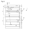
- the figure 6 is a view similar to that of the figure 2 except that, for the purpose of suppressing parasitic reflections and thereby improving the display contrast, a circular polarizer is placed above the transparent display unit TOLED 20, on the observer's side 4 38 which consists of a second absorbing polarizer 40 and a first quarter wave plate 42.
- a second quarter wave plate 44 is placed under the transparent display cell TOLED 20. This second Quarter-wave plate 44 is parallel to the first quarter-wave plate 42 or else disposed at 90 ° with respect to the first quarter-wave plate 42. It will be assumed that the transmission axis of the second absorbing polarizer 40 and the reflective axis of the reflective polarizer 34 are perpendicular.
- the present invention teaches to have a circular polarizer 38 above the transparent display cell TOLED 20 and a second quarter-wave plate 44 under the transparent display cell TOLED 20.
- the ambient light 46 which enters the display unit 1 according to the invention is polarized linearly by the second absorbing polarizer 40, and then polarized Circularly through the first quarter-wave plate 42.
- the circularly-polarized ambient light 46 When passing through the transparent display cell TOLED 20, the circularly-polarized ambient light 46 is partially reflected by the transparent upper and lower electrodes 25, 26 of the transparent display cell. TOLED 20, this reflected light undergoes a phase shift, which has the effect of transforming its circular polarization circular polarization opposite direction of rotation. Thus, when the reflected light crosses again the circular polarizer 38, it is absorbed by the latter. In this way, it is possible to eliminate the stray light that is reflected on the electrodes 25, 26 of the transparent display cell TOLED 20. The remaining ambient light 46 passes through the transparent display cell TOLED 20, and then is polarized linearly as it passes through the second quarter wave plate 44 in a direction perpendicular to the transmission axis of the second absorbing polarizer 40.
- first and second quarter wave plates 42 and 44 are parallel to each other.
- the direction of polarization of the ambient light 46 is rotated 90 °, so that it is finally absorbed by the solar cell 10.
- the display is done in clear on a dark background.
- the display unit 1 is in negative contrast.
- the ambient light 46 passes through the reflective liquid crystal display cell 60 without modification, so that it falls on the reflective polarizer 34 in accordance with FIG. direction of polarization which is parallel to the axis of reflection of the latter.
- the ambient light 46 is thus reflected by the reflective polarizer 34, then passes through the reflective liquid crystal display cell 60 without modification.
- the ambient light 46 is then circularly polarized by the second quarter-wave plate 44, then passes through without modification the circular polarizer 38 and is perceptible by the observer 4.
- the reflective liquid crystal display cell is selected from the group consisting of helical nematic-type liquid crystal display cells, helical super-nematic type liquid crystal display cells, and display cells. liquid crystal type vertical alignment.
- the reflective liquid crystal display cell may be a bistable display cell.
Landscapes
- Physics & Mathematics (AREA)
- Nonlinear Science (AREA)
- Chemical & Material Sciences (AREA)
- Optics & Photonics (AREA)
- Crystallography & Structural Chemistry (AREA)
- General Physics & Mathematics (AREA)
- Mathematical Physics (AREA)
- Devices For Indicating Variable Information By Combining Individual Elements (AREA)
- Life Sciences & Earth Sciences (AREA)
- Inorganic Chemistry (AREA)
- Sustainable Development (AREA)
- Liquid Crystal (AREA)
- Electroluminescent Light Sources (AREA)
- Illuminated Signs And Luminous Advertising (AREA)
Abstract
Description
- La présente invention concerne un ensemble d'affichage hybride comprenant une cellule solaire. Plus précisément, la présente invention concerne un tel ensemble d'affichage comprenant deux dispositifs d'affichage superposés sous lesquels est disposée une cellule solaire.
- La lisibilité des informations affichées par les dispositifs d'affichage tels que les cellules d'affichage à cristaux liquides ou bien les dispositifs d'affichage à diodes organiques électroluminescentes est très dépendante des conditions de luminosité ambiante. Avec certains dispositifs d'affichage, les informations affichées peuvent être lues dans de bonnes conditions dans un environnement éclairé, mais par contre sont difficiles à lire dans un environnement sombre. Inversement, d'autres catégories de dispositifs d'affichage fournissent un affichage de bonne qualité dans la pénombre ou l'obscurité, mais sont difficilement lisibles en plein jour.
- A titre d'exemple, considérons les cellules d'affichage à cristal liquide de type transflectif, c'est-à-dire des cellules d'affichage à cristal liquide capables d'afficher des informations qui vont être visibles de jour grâce à un phénomène de réflexion, et qui vont être également visibles dans le noir par transmission en utilisant un dispositif de rétroéclairage. De telles cellules d'affichage à cristal liquide de type transflectif sont optimisées pour pouvoir réfléchir au mieux la lumière du soleil et ainsi garantir une bonne lisibilité des informations affichées dans des conditions de forte luminosité ambiante. Cependant, afin que de telles cellules d'affichage à cristal liquide de type transflectif puissent réfléchir au mieux la lumière du soleil, leur efficacité en transmission est fortement limitée. Ainsi, lorsque le dispositif de rétroéclairage est activé afin de permettre de lire les informations affichées dans la pénombre, une majeure partie de la lumière émise par le dispositif de rétroéclairage se perd dans des phénomènes d'absorption. Le rendement énergétique est donc médiocre. En outre, les qualités optiques des informations affichées par la cellule à cristal liquide sont fortement dépendantes de l'angle de vue.
- En ce qui concerne les dispositifs d'affichage de type émissif tels que les dispositifs d'affichage à diodes organiques électroluminescentes, ils présentent des qualités optiques qui sont supérieures à celles des cellules d'affichage à cristal liquide, ces qualités optiques ne dépendant notamment pas de l'angle de vue. Néanmoins, ces dispositifs d'affichage de type émissif de haute qualité ne permettent pas un fonctionnement en mode réflectif. Les informations qu'ils affichent sont donc très lisibles dans la pénombre ou l'obscurité, mais deviennent difficilement lisibles dès qu'elles sont observées en extérieur. Pour remédier à ce problème, il est possible d'augmenter la quantité de courant fournie aux dispositifs d'affichage émissifs afin d'accroître la brillance des diodes électroluminescentes et ainsi garantir un minimum de lisibilité. Toutefois, même en conditions d'utilisation normale, ces dispositifs d'affichage émissifs consomment davantage qu'une cellule à cristal liquide de type réflectif. Leur consommation électrique est telle qu'il est difficilement envisageable de les conserver allumés en permanence, en particulier lorsqu'ils sont embarqués dans un objet portable de petites dimensions tels qu'une montre-bracelet dont la seule source d'énergie est une pile dont on souhaite habituellement qu'elle dure au moins un an.
- La présente invention a pour but de remédier aux problèmes susmentionnés ainsi qu'à d'autres encore en procurant un ensemble d'affichage dont les besoins en énergie peuvent être satisfaits même lorsqu'il est embarqué dans un objet portable de petites dimensions tel qu'une montre-bracelet dont les réserves en énergie sont pourtant limitées. La présente invention procure également un ensemble d'affichage dont le fonctionnement est satisfaisant aussi bien dans un environnement fortement éclairé que dans un environnement sombre.
- A cet effet, la présente invention concerne un ensemble d'affichage pour un objet portable, cet ensemble d'affichage comprenant un premier dispositif d'affichage émissif au moins partiellement transparent situé du côté d'un observateur, un second dispositif d'affichage réflectif et une cellule solaire étant disposés dans cet ordre sous le premier dispositif d'affichage émissif, le second dispositif d'affichage réflectif étant capable de commuter entre un état transparent lorsqu'il est au repos et un état réflectif lorsqu'il est activé.
- Selon une caractéristique complémentaire de l'invention, le dispositif d'affichage émissif transparent est fixé sur le dispositif d'affichage réflectif.
- Selon une autre caractéristique de l'invention, le dispositif d'affichage émissif transparent est collé sur le dispositif d'affichage réflectif au moyen d'un adhésif en film ou d'une couche de colle liquide.
- Grâce à ces caractéristiques, la présente invention procure un ensemble d'affichage pour un objet portable tel qu'une montre-bracelet dont le fonctionnement est optimal quelles que soient les conditions d'éclairement ambiant. En plein jour, les informations seront préférentiellement affichées par le dispositif d'affichage réflectif. En effet, ce dispositif d'affichage réflectif, mettant à profit un phénomène de réflexion de la lumière du soleil pour afficher les informations, est économe en énergie. Il peut donc rester allumé en permanence et offre une bonne lisibilité des informations. Inversement, dans la pénombre ou l'obscurité, les informations seront affichées par le dispositif d'affichage émissif. Un tel dispositif d'affichage émissif consomme davantage de courant qu'un dispositif d'affichage réflectif, mais les informations qu'il affiche sont visibles de nuit ou dans l'obscurité avec de très bonnes propriétés optiques qui sont notamment indépendantes de l'angle de vue. De plus, si ce type de dispositif d'affichage émissif est principalement utilisé de nuit ou dans des environnements faiblement éclairés, sa consommation de courant électrique reste néanmoins limitée car il n'est pas nécessaire, dans de telles conditions, de l'alimenter à pleine puissance. Au contraire, une faible puissance électrique est déjà suffisante pour permettre une lecture aisée des informations. Ainsi, à la différence d'une cellule d'affichage à cristal liquide de type transflectif qui cherche à parvenir à un compromis entre la réflectivité de son mode réflectif, et la consommation d'énergie électrique de son dispositif de rétroéclairage en mode transmissif, l'ensemble d'affichage selon l'invention propose de combiner deux dispositifs d'affichage, l'un purement réflectif et l'autre purement émissif, sans compromettre les performances ni de l'un, ni de l'autre de ces deux dispositifs d'affichage. En outre, en enseignant de disposer une cellule solaire sous les deux dispositifs d'affichage superposés, la présente invention permet l'intégration d'un tel ensemble dans un objet portable de petites dimensions dont les réserves en énergie électrique sont nécessairement limitées. En effet, on a constaté que la quantité de lumière qui parvenait à la cellule solaire à travers l'ensemble des deux dispositifs d'affichage superposés était suffisante pour fournir, par phénomène de conversion photoélectrique, la quantité d'énergie électrique nécessaire au fonctionnement des deux dispositifs d'affichage superposés. Par conséquent, les réserves d'énergie électrique de l'objet portable sont peu, ou pas sollicitées par le fonctionnement des deux dispositifs d'affichage superposés.
- Selon un mode de réalisation de l'invention, le premier dispositif d'affichage comprend une cellule d'affichage émissive transparente, et le second dispositif d'affichage comprend une cellule d'affichage à cristal liquide réflective de type nématique en hélice ou super-nématique en hélice ou bien encore à alignement vertical. La cellule d'affichage émissive transparente est au choix une cellule d'affichage émissive transparente à diodes organiques électroluminescentes ou une cellule d'affichage émissive transparente inorganique.
- Selon une caractéristique complémentaire de l'invention, la cellule d'affichage à diodes organiques électroluminescentes est disposée entre un polariseur circulaire et une lame quart d'onde, le polariseur circulaire étant placé du côté de l'observateur.
- L'adressage des zones électroluminescentes des cellules d'affichage à diodes organiques électroluminescentes est assuré par des électrodes transparentes le plus souvent réalisées à l'aide d'un matériau métallique ou d'un oxyde métallique. Ces électrodes provoquent donc assez souvent de légers phénomènes de réflexion optique qui induisent une dégradation du contraste, ce qui nuit à la lisibilité des informations affichées par les cellules d'affichage à diodes organiques électroluminescentes. Pour remédier à cet inconvénient, la présente invention enseigne de disposer la cellule d'affichage à diodes organiques électroluminescentes entre un polariseur circulaire et une lame quart d'onde, le polariseur circulaire étant placé du côté de l'observateur. Ainsi, une des composantes de polarisation de la lumière ambiante qui pénètre dans l'ensemble d'affichage selon l'invention est absorbée par le polariseur circulaire, tandis que l'autre composante de polarisation de la lumière est polarisée circulairement. Lorsqu'en traversant la cellule d'affichage à diodes organiques électroluminescentes, la lumière ambiante polarisée circulairement est partiellement réfléchie par les électrodes transparentes de la cellule d'affichage à diodes organiques électroluminescentes, cette lumière réfléchie subit un déphasage, ce qui a pour effet de transformer sa polarisation circulaire en polarisation circulaire de sens de rotation opposé. Ainsi, lorsque la lumière réfléchie traverse à nouveau le polariseur circulaire, elle est absorbée par ce dernier. De cette manière, il est possible d'éliminer la lumière parasite qui se réfléchit sur les électrodes de la cellule d'affichage à diodes organiques électroluminescentes, et de ne conserver que la lumière qui traverse la cellule d'affichage à diodes organiques électroluminescentes sans modification. Par suite, la lumière se retrouve à nouveau polarisée linéairement après son passage à travers la lame quart d'onde placée sous la cellule d'affichage à diodes organiques électroluminescentes et sera finalement absorbée ou réfléchie par la cellule d'affichage à cristal liquide réflective selon que l'on recherche un affichage à contraste positif ou négatif.
- D'autres caractéristiques et avantages de la présente invention ressortiront plus clairement de la description détaillée qui suit d'un mode de réalisation de l'ensemble d'affichage selon l'invention, cet exemple étant donné à titre purement illustratif et non limitatif seulement en liaison avec le dessin annexé sur lequel :
- la
figure 1 est une vue schématique en coupe illustrant un ensemble d'affichage selon l'invention comprenant un premier dispositif d'affichage émissif au moins partiellement transparent situé du côté d'un observateur, un second dispositif d'affichage réflectif et une cellule solaire étant disposés dans cet ordre sous le premier dispositif d'affichage émissif ; - la
figure 2 est une vue en coupe d'un exemple de réalisation d'un ensemble d'affichage selon l'invention dans lequel le premier dispositif d'affichage est une cellule d'affichage émissive transparente à diodes organiques électroluminescentes, et le second dispositif d'affichage est une cellule d'affichage à cristal liquide réflective de type nématique en hélice, une cellule solaire étant disposée sous cet ensemble d'affichage ; - les
figures 3A à 3D illustrent schématiquement le mode de fonctionnement de l'ensemble d'affichage illustré à lafigure 2 selon que la cellule d'affichage à diodes organiques électroluminescentes et la cellule d'affichage à cristal liquide nématique en hélice sont actives ou passives ; - la
figure 4 est une vue similaire à celle de lafigure 2 dans laquelle le second dispositif d'affichage est une cellule d'affichage à cristal liquide réflective à alignement vertical ; - les
figures 5A à 5D illustrent schématiquement le mode de fonctionnement de l'ensemble d'affichage illustré à lafigure 4 selon que la cellule d'affichage à diodes organiques électroluminescentes et la cellule d'affichage à cristal liquide aligné verticalement sont actives ou passives, et - la
figure 6 est une vue similaire à celle de lafigure 2 à ceci près que, dans le but de supprimer les réflexions parasites et d'améliorer ainsi le contraste d'affichage, on place au-dessus de la cellule d'affichage transparente à diodes organiques électroluminescentes, du côté de l'observateur, un polariseur circulaire qui se compose d'un second polariseur absorbant et d'une première lame quart d'onde. - La présente invention procède de l'idée générale inventive qui consiste à procurer un ensemble d'affichage qui soit capable d'afficher de manière lisible des informations à la fois en plein jour et dans la pénombre ou l'obscurité et dont la consommation d'énergie électrique soit optimale. Pour atteindre cet objectif, la présente invention enseigne de combiner un dispositif d'affichage de type émissif avec un dispositif d'affichage qui est agencé pour pouvoir commuter entre un état de repos dans lequel il est transparent et un état actif dans lequel il est capable de réfléchir la lumière ambiante. Le dispositif d'affichage de type émissif est typiquement une cellule d'affichage à diodes organiques électroluminescentes, tandis que le dispositif d'affichage de type réflectif est typiquement une cellule d'affichage à cristal liquide. Pour l'affichage des informations en plein jour, on privilégie l'utilisation du dispositif d'affichage de type réflectif qui, par réflexion de la lumière du soleil, permet d'afficher les informations de manière claire et lisible tout en consommant peu d'énergie électrique. Pour l'affichage des informations dans la pénombre ou l'obscurité, on privilégie l'utilisation du dispositif d'affichage émissif. Grâce à ses excellentes propriétés optiques, notamment en termes de contraste et de reproduction des couleurs, un tel dispositif d'affichage émissif permet d'afficher un grand nombre d'informations de manière très lisible. En particulier, la lisibilité des informations affichées n'est pas dépendante de l'angle de vue. De plus, dans la pénombre ou l'obscurité, il est possible de réduire de manière significative la consommation d'énergie d'un tel dispositif d'affichage émissif tout en garantissant une bonne lisibilité des informations affichées. On dispose ainsi d'un ensemble d'affichage qui comprend un dispositif d'affichage réflectif placé à la base de l'empilement et qui est capable d'afficher des informations en permanence en consommant très peu d'énergie, et un dispositif d'affichage émissif placé sur le dessus de l'empilement et qui est capable d'afficher à la demande des informations de manière très lisible dans la pénombre ou l'obscurité. On s'est rendu compte en outre qu'en disposant une cellule solaire sous les deux dispositifs d'affichage superposés, la cellule solaire produisait, par effet de conversion photoélectrique, un courant électrique suffisant pour permettre le fonctionnement des deux dispositifs d'affichage superposés. Il est donc possible d'intégrer un tel ensemble d'affichage dans un objet portable de petites dimensions tel qu'une montre-bracelet dont les capacités de stockage en énergie électrique sont pourtant limitées.
- La
figure 1 est une vue schématique en coupe d'un ensemble d'affichage selon l'invention. Désigné dans son ensemble par la référence numérique générale 1, cet ensemble d'affichage comprend un premier dispositif d'affichage émissif 2 au moins partiellement transparent disposé du côté d'un observateur 4, et un second dispositif d'affichage réflectif 6 lui aussi au moins partiellement transparent disposé sous le premier dispositif d'affichage émissif 2. Au sens de la présente invention, le premier dispositif d'affichage émissif 2 est capable de commuter entre un état passif dans lequel il est au moins partiellement transparent, et un état actif dans lequel il émet de la lumière pour afficher une information. Quant au second dispositif d'affichage réflectif 6, il est capable de commuter entre un état passif dans lequel il est transparent et un état actif dans lequel il est capable de réfléchir la lumière ambiante - De préférence mais non impérativement, le premier dispositif d'affichage émissif 2 est solidarisé sur le second dispositif d'affichage réflectif 6 au moyen d'une couche adhésive transparente 8. Cette couche adhésive transparente 8 peut être formée d'un adhésif en film ou d'une couche de colle liquide acrylique ou silicone. Cette couche adhésive transparente 8 a pour objet d'éviter les problèmes de réflexions parasites qui surviendraient si les deux dispositifs d'affichage 2, 6 étaient séparés par une couche d'air et qui dégraderaient la qualité optique de l'ensemble d'affichage 1 selon l'invention.
- Enfin, une cellule solaire 10 capable de fournir de l'énergie électrique en exploitant le phénomène de conversion photoélectrique est disposée sous le second dispositif d'affichage réflectif 6. A titre préféré mais non limitatif, la cellule solaire 10 est collée sous le second dispositif d'affichage réflectif 6 au moyen d'une couche adhésive transparente 12.
- Dans tout ce qui suit, l'invention sera décrite en référence à une cellule d'affichage émissive transparente du type à diodes organiques électroluminescentes. On comprendra néanmoins que cet exemple est donné à titre purement illustratif et non limitatif seulement et que d'autres types de cellules d'affichage émissive transparentes tels que des cellules d'affichage émissives transparentes inorganiques encore connues sous leur dénomination anglo-saxonne Electro Luminescent Display ou ELD peuvent être envisagés sans sortir des limites de l'invention telles que définies par les revendications annexées.
- La
figure 2 est une vue en coupe détaillée d'un exemple de réalisation de l'ensemble d'affichage 1 selon l'invention dans le cas où le premier dispositif d'affichage émissif 2 comprend une cellule d'affichage émissive transparente 20 à diodes organiques électroluminescentes qui sera désignée dans tout ce qui suit par cellule d'affichage transparente TOLED (Transparent Organic Light Emitting Diode). Quant au second dispositif d'affichage réflectif 6, il comprend une cellule d'affichage à cristal liquide réflective 60 de type nématique en hélice, également connue sous sa dénomination anglo-saxonne Twist Nematic ou TN. - Plus précisément, la cellule d'affichage transparente TOLED 20 comprend un substrat transparent 21 réalisé en verre ou en un matériau plastique et un capot d'encapsulation 22 qui s'étend parallèlement à et à distance du substrat transparent 21. Le substrat transparent 21 et le capot d'encapsulation 22 sont réunis entre eux par un cadre de scellement 23 qui délimite un volume clos à l'abri de l'air et de l'humidité pour le confinement d'un empilement de couches électroluminescentes généralement désigné par la référence numérique 24. Une électrode supérieure transparente 25 réalisée par exemple en oxyde d'étain-indium ou ITO et une électrode inférieure transparente 26 réalisée par exemple au moyen d'un matériau métallique tel que l'aluminium ou l'argent ou d'un oxyde métallique tel que l'ITO ou l'oxyde de zinc-indium sont structurées de part et d'autre de l'empilement des couches électroluminescentes 24. Ces électrodes 25, 26, réalisées en un matériau métallique, sont légèrement réfléchissantes. Les cellules d'affichage transparentes à diodes organiques électroluminescentes sont disponibles soit avec un adressage direct dans les cas où il s'agit simplement d'afficher des icônes ou des segments, soit avec un adressage du type à matrice passive dans le cas d'un affichage matriciel à points. Dans le cas d'un affichage à matrice de points, on peut également avoir affaire à un adressage du type à matrice active combiné avec des transistors transparents du type Thin Film Transistor ou TFT destinés à contrôler le courant et qui sont ménagés dans les pixels d'affichage.
- D'autre part, la cellule d'affichage à cristal liquide réflective 60 comprend un substrat avant 61 disposé du côté de l'observateur 4 et un substrat arrière 62 qui s'étend parallèlement à et à distance du substrat avant 61. Les substrats avant 61 et arrière 62 sont réunis entre eux par un cadre de scellement 63 qui délimite une enceinte étanche 64 pour le confinement d'un cristal liquide dont les propriétés optiques sont modifiées par application d'une tension appropriée à un point de croisement considéré entre des électrodes transparentes 65a ménagées sur une face inférieure du substrat avant 61 et des contre-électrodes transparentes 65b ménagées sur une face supérieure de substrat arrière 62. Les électrodes 65a et les contre-électrodes 65b sont réalisées en un matériau transparent électriquement conducteur tel que de l'oxyde d'indium-zinc ou de l'oxyde d'indium-étain, ce dernier matériau étant mieux connu sous sa dénomination anglo-saxonne Indium Tin Oxyde ou ITO.
- Dans le cas de la présente invention, toutes les phases des cristaux liquides telles que nématique en hélice (Twist Nematic ou TN en terminologie anglo-saxonne), super-nématique en hélice (Super Twist Nematic ou STN en terminologie anglo-saxonne) ou bien encore à alignement vertical (Vertically Aligned ou VA en terminologie anglo-saxonne) peuvent être envisagées. De même, tous les types d'adressage tels qu'adressage direct, adressage par matrice active ou adressage multiplexé d'une matrice passive peuvent être envisagés.
- Un polariseur absorbant 30 est collé sur une face supérieure du substrat avant 61 de la cellule d'affichage à cristal liquide réflective 60 au moyen d'une couche adhésive 32. Cette couche adhésive 32 peut être formée d'un adhésif en film ou d'une couche de colle liquide. La colle utilisée pour solidariser le polariseur absorbant 30 sur la cellule d'affichage à cristal liquide réflective 60 peut-être transparente ou légèrement diffusante selon que l'on cherche à obtenir une réflexion spéculaire ou bien diffuse. Quant au polariseur absorbant 30, il peut être, par exemple, du type à iodine ou à colorant.
- Un polariseur réflectif absorbant 34 est collé sur une face inférieure du substrat arrière 62 de la cellule d'affichage à cristal liquide réflective 60 au moyen d'une couche adhésive 36 qui peut être transparente ou légèrement diffusante selon que l'on cherche à obtenir une réflexion spéculaire ou bien diffuse.
- On examine maintenant en liaison avec les
figures 3A à 3D les principes de fonctionnement de l'ensemble d'affichage 1 selon l'invention selon que la cellule d'affichage transparente TOLED 20 et la cellule d'affichage à cristal liquide réflective 60 sont en service ou non. On supposera, à titre d'exemple purement illustratif et nullement limitatif seulement, que la cellule d'affichage à cristal liquide réflective 60 est une cellule à cristal liquide nématique en hélice TN et que l'axe de transmission du polariseur absorbant 30 et l'axe de réflexion du polariseur réflectif 34 sont parallèles. - A la
figure 3A , la cellule d'affichage transparente TOLED 20 et la cellule d'affichage à cristal liquide réflective TN 60 sont toutes les deux éteintes. La lumière ambiante, désignée par la référence numérique 46, traverse sans modification la cellule d'affichage transparente TOLED 20, puis est polarisée linéairement par le polariseur absorbant 30. La lumière ambiante 46 subit ensuite une rotation de 90° lorsqu'elle traverse la cellule d'affichage à cristal liquide réflective TN 60, de sorte que lorsqu'elle tombe sur le polariseur réflectif 34, sa direction de polarisation est perpendiculaire à l'axe de réflexion du polariseur réflectif 34 et elle traverse donc ce dernier avant d'être absorbée par la cellule solaire 10. La cellule d'affichage à cristal liquide réflective TN 60 apparaît donc sombre lorsqu'elle est éteinte, ce qui signifie que les informations qu'elle va afficher vont apparaître en clair sur un fond sombre. L'affichage des informations est donc à contraste négatif. Bien entendu, un affichage des informations selon un contraste positif pourrait être obtenu simplement en veillant à ce que l'axe de transmission du polariseur 30 et l'axe de réflexion du polariseur réflectif absorbant 34 soient perpendiculaires. Dans ce cas, la lumière ambiante 46 atteint la cellule solaire seulement dans les zones de la cellule d'affichage à cristal liquide réflective TN 60 qui sont commutées. - A la
figure 3B , la cellule d'affichage transparente TOLED 20 est activée, tandis que la cellule d'affichage à cristal liquide réflective TN 60 est désactivée. La lumière émise par la cellule d'affichage transparente TOLED 20 parvient à l'observateur 4 sans modification, tandis que la cellule d'affichage à cristal liquide réflective TN 60 apparaît sombre. Les informations affichées par la cellule d'affichage transparente TOLED 20 se détachent donc sur un fond sombre. - A la
figure 3C , la cellule d'affichage transparente TOLED 20 est éteinte, tandis que la cellule d'affichage à cristal liquide réflective TN 60 est activée. Comme déjà expliqué ci-dessus, les zones non commutées de la cellule d'affichage à cristal liquide réflective TN 60 apparaissent sombres. Par contre, dans les zones commutées de la cellule d'affichage à cristal liquide réflective TN 60, la lumière ambiante 46 traverse ces zones sans modification, de sorte que la lumière ambiante 46 tombe sur le polariseur réflectif 34 avec une direction de polarisation parallèle à l'axe de réflexion de ce polariseur réflectif 34. La lumière ambiante 46 est donc réfléchie en arrière et traverse successivement la cellule d'affichage à cristal liquide réflective TN 60, le polariseur absorbant 30 et la cellule d'affichage transparente TOLED 20 sans modification, de sorte qu'elle est perceptible par l'observateur 4. Les informations s'affichent donc en clair sur un fond sombre. - A la
figure 3D , la cellule d'affichage transparente TOLED 20 et la cellule d'affichage à cristal liquide réflective TN 60 sont toutes deux activées. La lumière émise par la cellule d'affichage transparente TOLED 20 est directement perceptible par l'observateur 4. La lumière ambiante 46 qui traverse les zones non commutées de la cellule d'affichage à cristal liquide réflective TN 60 est absorbée par la cellule solaire 10, de sorte que ces zones apparaissent sombres. Enfin, la lumière ambiante 46 qui traverse les zones commutées de la cellule d'affichage à cristal liquide réflective TN 60 est réfléchie par le polariseur réflectif 34, de sorte que ces zones apparaissent claires. - La
figure 4 est une vue en coupe d'un exemple de réalisation de l'ensemble d'affichage 1 selon l'invention dans le cas où le premier dispositif d'affichage 2 comprend une cellule d'affichage émissive transparente 20 à diodes organiques électroluminescentes qui sera désignée dans tout ce qui suit par cellule d'affichage transparente TOLED (Transparent Organic Light Emitting Diode). Quant au second dispositif d'affichage 6, il comprend une cellule d'affichage à cristal liquide réflective 600 à alignement vertical, également connue sous sa dénomination anglo-saxonne Vertically Aligned ou VA. - On examine maintenant en liaison avec les
figures 5A à 5D les principes de fonctionnement de l'ensemble d'affichage 1 selon l'invention selon que la cellule d'affichage transparente TOLED 20 et la cellule d'affichage à cristal liquide réflective VA 600 sont en service ou non. On supposera, à titre d'exemple purement illustratif et nullement limitatif seulement, que l'axe de transmission du polariseur absorbant 30 et l'axe de réflexion du polariseur réflectif 34 sont perpendiculaires. - A la
figure 5A , la cellule d'affichage transparente TOLED 20 et la cellule d'affichage à cristal liquide réflective VA 600 sont toutes les deux éteintes. La lumière ambiante, désignée par la référence numérique 46, traverse successivement sans modification la cellule d'affichage transparente TOLED 20 et la cellule d'affichage à cristal liquide réflective VA 600, de sorte que lorsqu'elle tombe sur le polariseur réflectif 34, sa direction de polarisation est perpendiculaire à l'axe de réflexion du polariseur réflectif 34. Elle traverse donc ce dernier sans modification et est finalement absorbée par la cellule solaire 10. La cellule d'affichage à cristal liquide réflective VA 600 apparaît donc sombre lorsqu'elle est éteinte, ce qui signifie que les informations qu'elle va afficher vont apparaître en clair sur un fond sombre. L'affichage des informations est donc à contraste négatif. Bien entendu, un affichage des informations selon un contraste positif peut être obtenu simplement en veillant à ce que l'axe de transmission du polariseur absorbant 30 et l'axe de réflexion du polariseur réflectif34 soient parallèles. - A la
figure 5B , la cellule d'affichage transparente TOLED 20 est activée, tandis que la cellule d'affichage à cristal liquide réflective VA 600 est désactivée. La lumière émise par la cellule d'affichage transparente TOLED 20 parvient à l'observateur 4 sans modification, tandis que la cellule d'affichage à cristal liquide réflective VA 600 apparaît sombre. Les informations affichées par la cellule d'affichage transparente TOLED 20 se détachent donc sur un fond sombre. - A la
figure 5C , la cellule d'affichage transparente TOLED 20 est éteinte, tandis que la cellule d'affichage à cristal liquide réflective VA 600 est activée. - Dans une cellule à cristal liquide à alignement vertical, les couches d'alignement sont orientées à 45° par rapport aux axes de polarisation des polariseurs. D'autre part, le résultat du produit entre la biréfringence des molécules de cristal liquide et la distance entre les substrats avant et arrière est choisi de façon que, lorsque le cristal liquide est commuté, il se comporte vis-à-vis de la direction de polarisation de la lumière comme une lame demi-onde. Par conséquent, comme cette lame demi-onde est placée à 45° par rapport à l'axe de polarisation du polariseur absorbant, elle provoque une rotation de 90° de la direction de polarisation de la lumière. Ainsi, la lumière ambiante 46 subit une rotation de 90° lorsqu'elle traverse les zones commutées de la cellule d'affichage à cristal liquide réflective VA 600, de sorte que lorsqu'elle tombe sur le polariseur réflectif 34, sa direction de polarisation est parallèle à l'axe de réflexion du polariseur réflectif 34 et elle est donc réfléchie par ce dernier. Quant à la lumière ambiante 46 qui traverse les zones non commutées de la cellule d'affichage à cristal liquide réflective VA 600, elle est absorbée par la cellule solaire 10. Les informations s'affichent donc en clair sur un fond sombre, c'est-à-dire avec un contraste négatif.
- A la
figure 5D , la cellule d'affichage transparente TOLED 20 et la cellule d'affichage à cristal liquide réflective VA 600 sont toutes deux activées. La lumière émise par la cellule d'affichage transparente TOLED 20 est directement perceptible par l'observateur 4. La lumière ambiante 46 qui traverse les zones non commutées de la cellule d'affichage à cristal liquide réflective VA 600 est absorbée par la cellule solaire 10, de sorte que ces zones apparaissent sombres. Enfin, la lumière ambiante 46 qui traverse les zones commutées de la cellule d'affichage à cristal liquide réflective VA 600 est réfléchie par le polariseur réflectif 34, de sorte que ces zones apparaissent claires. - La
figure 6 est une vue similaire à celle de lafigure 2 à ceci près que, dans le but de supprimer les réflexions parasites et d'améliorer ainsi le contraste d'affichage, on place au-dessus de la cellule d'affichage transparente TOLED 20, du côté de l'observateur 4, un polariseur circulaire 38 qui se compose d'un second polariseur absorbant 40 et d'une première lame quart d'onde 42. D'autre part, une seconde lame quart d'onde 44 est placée sous la cellule d'affichage transparente TOLED 20. Cette seconde lame quart d'onde 44 est parallèle à la première lame quart d'onde 42 ou bien disposée à 90° par rapport à la première lame quart d'onde 42. On supposera que l'axe de transmission du second polariseur absorbant 40 et l'axe de réflexion du polariseur réflectif 34 sont perpendiculaires. - L'adressage des zones électroluminescentes des cellules d'affichage à diodes organiques électroluminescentes est assuré par des électrodes transparentes le plus souvent réalisées à l'aide d'un matériau métallique ou d'un oxyde métallique. Ces électrodes provoquent donc assez souvent des phénomènes de réflexion optique qui induisent une dégradation du contraste, ce qui nuit à la lisibilité des informations affichées par les cellules d'affichage à diodes organiques électroluminescentes. Pour remédier à cet inconvénient, la présente invention enseigne de disposer un polariseur circulaire 38 au-dessus de la cellule d'affichage transparente TOLED 20 et une seconde lame quart d'onde 44 sous la cellule d'affichage transparente TOLED 20. Ainsi, la lumière ambiante 46 qui pénètre dans l'ensemble d'affichage 1 selon l'invention est polarisée linéairement par le second polariseur absorbant 40, puis polarisée circulairement par la première lame quart d'onde 42. Lorsqu'en traversant la cellule d'affichage transparente TOLED 20, la lumière ambiante 46 polarisée circulairement est partiellement réfléchie par les électrodes supérieure et inférieure transparentes 25, 26 de la cellule d'affichage transparente TOLED 20, cette lumière réfléchie subit un déphasage, ce qui a pour effet de transformer sa polarisation circulaire en polarisation circulaire de sens de rotation opposé. Ainsi, lorsque la lumière réfléchie traverse à nouveau le polariseur circulaire 38, elle est absorbée par ce dernier. De cette manière, il est possible d'éliminer la lumière parasite qui se réfléchit sur les électrodes 25, 26 de la cellule d'affichage transparente TOLED 20. La lumière ambiante 46 restante traverse sans modification la cellule d'affichage transparente TOLED 20, puis est polarisée linéairement lors de son passage à travers la seconde lame quart d'onde 44 selon une direction perpendiculaire à l'axe de transmission du second polariseur absorbant 40. On suppose en effet que les première et seconde lames quart d'onde 42 et 44 sont parallèles entre elles. Lors du passage de la lumière ambiante 46 à travers la cellule d'affichage à cristal liquide réflective 60, la direction de polarisation de la lumière ambiante 46 est tournée de 90°, de sorte qu'elle est finalement absorbée par la cellule solaire 10.
- L'affichage se fait donc en clair sur un fond sombre. Autrement dit, l'ensemble d'affichage 1 est à contraste négatif. En effet, dans les zones commutées de la cellule d'affichage à cristal liquide réflective 60, la lumière ambiante 46 traverse la cellule d'affichage à cristal liquide réflective 60 sans modification, de sorte qu'elle tombe sur le polariseur réflectif 34 selon une direction de polarisation qui est parallèle à l'axe de réflexion de ce dernier. La lumière ambiante 46 est donc réfléchie par le polariseur réflectif 34, puis traverse la cellule d'affichage à cristal liquide réflective 60 sans modification. La lumière ambiante 46 est ensuite polarisée circulairement par la seconde lame quart d'onde 44, puis traverse sans modification le polariseur circulaire 38 et est perceptible par l'observateur 4.
- A titre de variante, il est possible d'envisager de disposer la seconde lame quart d'onde 44 entre la cellule d'affichage à cristal liquide réflective 60 et le polariseur réflectif absorbant 34.
- Il va de soi que la présente invention n'est pas limitée aux modes de réalisation qui viennent d'être décrits et que diverses modifications et variantes simples peuvent être envisagées par l'homme du métier sans sortir du cadre de l'invention tel que défini par les revendications annexées à la présente demande de brevet. On comprendra en particulier que dire que la lumière ambiante traverse sans modification la cellule d'affichage à cristal liquide réflective ou la cellule d'affichage transparente TOLED est quelque peu un abus de langage. En effet, lorsque la lumière ambiante traverse ces cellules d'affichage, il se produit toujours des phénomènes minimes de réflexion parasite de la lumière. Ces réflexions parasites sont néanmoins tout à fait négligeables dans le cadre de la présente invention. On aura également compris de ce qui a été dit ci-dessus que parler d'électrodes « transparentes » est également quelque peu un abus de langage. En effet, bien que réalisées en un matériau transparent électriquement conducteur, ces électrodes sont toujours très légèrement réfléchissantes. La cellule d'affichage à cristal liquide réflective est choisie dans le groupe formé par les cellules d'affichage à cristal liquide de type nématique en hélice, les cellules d'affichage à cristal liquide de type super nématique en hélice et les cellules d'affichage à cristal liquide de type à alignement vertical. La cellule d'affichage à cristal liquide réflective peut être une cellule d'affichage bistable.
-
- Ensemble d'affichage 1
- Premier dispositif d'affichage émissif 2
- Observateur 4
- Second dispositif d'affichage réflectif 6
- Couche adhésive transparente 8
- Cellule solaire 10
- Couche adhésive transparente 12
- Cellule d'affichage transparente TOLED 20
- Substrat transparent 21
- Capot d'encapsulation 22
- Cadre de scellement 23
- Empilement de couches électroluminescentes 24
- Electrode supérieure transparente 25
- Electrode inférieure transparente 26
- Polariseur absorbant 30
- Couche adhésive 32
- Polariseur réflectif absorbant 34
- Couche adhésive 36
- Polariseur circulaire 38
- Second polariseur absorbant 40
- Première lame quart d'onde 42
- Seconde lame quart d'onde 44
- Lumière ambiante 46
- Cellule d'affichage à cristal liquide réflective TN 60
- Substrat avant 61
- Substrat arrière 62
- Cadre de scellement 63
- Enceinte étanche 64
- Electrodes transparentes 65a
- Contre-électrodes transparentes 65b
- Cellule d'affichage à cristal liquide réflective VA 600
Claims (11)
- Ensemble d'affichage pour un objet portable, cet ensemble d'affichage (1) comprenant un premier dispositif d'affichage émissif (2) au moins partiellement transparent situé du côté d'un observateur (4), un second dispositif d'affichage réflectif (6) et une cellule solaire (10) étant disposés dans cet ordre sous le premier dispositif d'affichage émissif (2), le second dispositif d'affichage réflectif (6) étant capable de commuter entre un état transparent dans lequel il n'affiche aucune information et un état réflectif lorsqu'il est activé.
- Ensemble d'affichage selon la revendication 1, caractérisé en ce que le dispositif d'affichage émissif (2) est collé sur le dispositif d'affichage réflectif (6).
- Ensemble d'affichage selon la revendication 2, caractérisé en ce que le dispositif d'affichage émissif (2) est collé sur le dispositif d'affichage réflectif (6) au moyen d'un adhésif en film ou d'une couche de colle liquide.
- Ensemble d'affichage selon l'une quelconque des revendications 1 à 3, caractérisé en ce que le premier dispositif d'affichage émissif (2) comprend une cellule d'affichage émissive transparente, et en ce que le second dispositif d'affichage réflectif (6) comprend une cellule d'affichage à cristal liquide réflective (60).
- Ensemble d'affichage selon la revendication 4, caractérisé en ce que la cellule d'affichage émissive transparente est une cellule d'affichage émissive transparente à diodes organiques électroluminescentes (20) ou une cellule d'affichage émissive transparente inorganique.
- Ensemble d'affichage selon l'une quelconque des revendications 4 ou 5, caractérisé en ce que la cellule d'affichage émissive transparente à diodes organiques électroluminescentes (20) comprend un empilement de couches électroluminescentes (24) pris en sandwich entre une électrode supérieure transparente (25) et une électrode inférieure transparente (26)
- Ensemble d'affichage selon l'une quelconque des revendications 4 à 6, caractérisé en ce que la cellule d'affichage à cristal liquide réflective (60) est choisie dans le groupe formé par les cellules à cristal liquide de type nématique en hélice, les cellules à cristal liquide de type super- nématique en hélice et les cellules d'affichage à cristal liquide à alignement vertical et en ce que l'adressage de ces cellules d'affichage à cristal liquide peut être de type direct, du type par matrice active ou du type adressage multiplexé d'une matrice passive.
- Ensemble d'affichage selon l'une quelconque des revendications 4 à 7, caractérisé en ce qu'un polariseur absorbant (30) est disposé sur une face supérieure de la cellule d'affichage à cristal liquide réflective (60), et en ce qu'un polariseur réflectif (34) est disposé sous une face inférieure du substrat arrière (62) de la cellule d'affichage à cristal liquide réflective (60).
- Ensemble d'affichage selon l'une quelconque des revendications 4 à 8, caractérisé en ce qu'un polariseur circulaire (38) qui se compose d'un second polariseur absorbant (40) et d'une première lame quart d'onde (42) est placé au-dessus de la cellule d'affichage émissive transparente à diodes organiques électroluminescentes (20), et en ce qu'une seconde lame quart d'onde (44) est placée sous la cellule d'affichage émissive transparente à diodes organiques électroluminescentes (20).
- Objet portable comprenant un ensemble d'affichage selon l'une quelconque des revendications précédentes.
- Objet portable selon la revendication 11, caractérisé en ce qu'il s'agit d'une montre-bracelet.
Priority Applications (1)
| Application Number | Priority Date | Filing Date | Title |
|---|---|---|---|
| EP15177931.1A EP3007015B1 (fr) | 2014-10-10 | 2015-07-22 | Ensemble d'affichage hybride comprenant une cellule solaire |
Applications Claiming Priority (2)
| Application Number | Priority Date | Filing Date | Title |
|---|---|---|---|
| EP14188413 | 2014-10-10 | ||
| EP15177931.1A EP3007015B1 (fr) | 2014-10-10 | 2015-07-22 | Ensemble d'affichage hybride comprenant une cellule solaire |
Publications (2)
| Publication Number | Publication Date |
|---|---|
| EP3007015A1 true EP3007015A1 (fr) | 2016-04-13 |
| EP3007015B1 EP3007015B1 (fr) | 2018-01-31 |
Family
ID=51730361
Family Applications (1)
| Application Number | Title | Priority Date | Filing Date |
|---|---|---|---|
| EP15177931.1A Active EP3007015B1 (fr) | 2014-10-10 | 2015-07-22 | Ensemble d'affichage hybride comprenant une cellule solaire |
Country Status (7)
| Country | Link |
|---|---|
| US (1) | US20160104751A1 (fr) |
| EP (1) | EP3007015B1 (fr) |
| JP (1) | JP2016081033A (fr) |
| KR (1) | KR101717848B1 (fr) |
| CN (1) | CN105513507A (fr) |
| HK (1) | HK1223722A1 (fr) |
| TW (1) | TWI546658B (fr) |
Cited By (1)
| Publication number | Priority date | Publication date | Assignee | Title |
|---|---|---|---|---|
| US10025319B2 (en) | 2016-08-31 | 2018-07-17 | Ford Global Technologies, Llc | Collision-warning system |
Families Citing this family (9)
| Publication number | Priority date | Publication date | Assignee | Title |
|---|---|---|---|---|
| US9385169B2 (en) | 2011-11-29 | 2016-07-05 | Ignis Innovation Inc. | Multi-functional active matrix organic light-emitting diode display |
| TWI632451B (zh) * | 2016-05-20 | 2018-08-11 | 矽創電子股份有限公司 | 太陽能顯示裝置 |
| KR102574641B1 (ko) * | 2016-07-19 | 2023-09-06 | 삼성디스플레이 주식회사 | 표시 장치 |
| CN108346683B (zh) * | 2018-02-09 | 2021-01-05 | 上海天马有机发光显示技术有限公司 | 发光结构、显示面板、显示装置及显示面板的控制方法 |
| CN109856830B (zh) * | 2019-01-03 | 2022-03-08 | 京东方科技集团股份有限公司 | 反射式显示面板及其制作方法、驱动方法、显示装置 |
| EP4016172B1 (fr) * | 2020-12-21 | 2025-05-14 | The Swatch Group Research and Development Ltd | Procédé de fabrication d'un dispositif d'affichage à cristal liquide et dispositif d'affichage a cristal liquide |
| JP2023147063A (ja) * | 2022-03-29 | 2023-10-12 | パナソニックIpマネジメント株式会社 | 表示装置 |
| CN115390311B (zh) * | 2022-08-25 | 2024-02-27 | 深圳市优奕视界有限公司 | 一种太阳能嵌入式的lcd屏幕及控制方法 |
| TWI891345B (zh) * | 2024-05-01 | 2025-07-21 | 虹彩光電股份有限公司 | 複合式自發電穿透顯示裝置 |
Citations (5)
| Publication number | Priority date | Publication date | Assignee | Title |
|---|---|---|---|---|
| EP0927917A1 (fr) * | 1997-07-18 | 1999-07-07 | Citizen Watch Co. Ltd. | Montre-bracelet |
| EP1004924A1 (fr) * | 1998-03-03 | 2000-05-31 | Citizen Watch Co., Ltd. | Affichage a cristaux liquides |
| US6229767B1 (en) * | 1997-08-04 | 2001-05-08 | Seiko Epson Corporation | Display device and electronic watch using the device |
| JP2003098984A (ja) * | 2001-09-25 | 2003-04-04 | Rohm Co Ltd | 画像表示装置 |
| JP2006276089A (ja) * | 2005-03-28 | 2006-10-12 | Dainippon Printing Co Ltd | ディスプレイ |
Family Cites Families (7)
| Publication number | Priority date | Publication date | Assignee | Title |
|---|---|---|---|---|
| EP0896241A3 (fr) * | 1997-08-04 | 1999-10-27 | Seiko Epson Corporation | Dispositf d'affichage et montre électronique l'utilisant |
| US6710831B1 (en) * | 2000-09-29 | 2004-03-23 | Rockwell Scientific Licensing, Llc | High brightness transflective LCD and method using tunable mirror |
| KR100621495B1 (ko) * | 2001-02-28 | 2006-09-13 | 가부시키가이샤 히타치 디스프레이즈 | 화상 표시 상태와 거울 상태를 전환 가능한 장치, 및이것을 구비한 기기 |
| JP2004038145A (ja) * | 2003-03-06 | 2004-02-05 | Seiko Epson Corp | 表示装置及びこれを備えた電子機器 |
| JP4997591B2 (ja) * | 2007-03-30 | 2012-08-08 | Nltテクノロジー株式会社 | タッチパネル付き液晶表示装置及び端末装置 |
| EP2437106B1 (fr) * | 2009-05-27 | 2020-11-18 | Sharp Kabushiki Kaisha | Dispositif d'affichage à cristaux liquides |
| TW201118823A (en) * | 2009-11-27 | 2011-06-01 | Univ Nat Taiwan | Transflective display device |
-
2015
- 2015-07-08 TW TW104122177A patent/TWI546658B/zh not_active IP Right Cessation
- 2015-07-08 US US14/794,132 patent/US20160104751A1/en not_active Abandoned
- 2015-07-22 EP EP15177931.1A patent/EP3007015B1/fr active Active
- 2015-07-24 KR KR1020150105132A patent/KR101717848B1/ko not_active Expired - Fee Related
- 2015-07-28 JP JP2015148442A patent/JP2016081033A/ja active Pending
- 2015-10-09 CN CN201510649139.3A patent/CN105513507A/zh active Pending
-
2016
- 2016-10-17 HK HK16111966.9A patent/HK1223722A1/zh unknown
Patent Citations (5)
| Publication number | Priority date | Publication date | Assignee | Title |
|---|---|---|---|---|
| EP0927917A1 (fr) * | 1997-07-18 | 1999-07-07 | Citizen Watch Co. Ltd. | Montre-bracelet |
| US6229767B1 (en) * | 1997-08-04 | 2001-05-08 | Seiko Epson Corporation | Display device and electronic watch using the device |
| EP1004924A1 (fr) * | 1998-03-03 | 2000-05-31 | Citizen Watch Co., Ltd. | Affichage a cristaux liquides |
| JP2003098984A (ja) * | 2001-09-25 | 2003-04-04 | Rohm Co Ltd | 画像表示装置 |
| JP2006276089A (ja) * | 2005-03-28 | 2006-10-12 | Dainippon Printing Co Ltd | ディスプレイ |
Cited By (1)
| Publication number | Priority date | Publication date | Assignee | Title |
|---|---|---|---|---|
| US10025319B2 (en) | 2016-08-31 | 2018-07-17 | Ford Global Technologies, Llc | Collision-warning system |
Also Published As
| Publication number | Publication date |
|---|---|
| KR101717848B1 (ko) | 2017-03-17 |
| HK1223722A1 (zh) | 2017-08-04 |
| TWI546658B (zh) | 2016-08-21 |
| TW201614418A (en) | 2016-04-16 |
| KR20160042755A (ko) | 2016-04-20 |
| US20160104751A1 (en) | 2016-04-14 |
| EP3007015B1 (fr) | 2018-01-31 |
| CN105513507A (zh) | 2016-04-20 |
| JP2016081033A (ja) | 2016-05-16 |
Similar Documents
| Publication | Publication Date | Title |
|---|---|---|
| EP2963506B1 (fr) | Ensemble d'affichage comprenant deux dispositifs d'affichage superposés | |
| EP3007015B1 (fr) | Ensemble d'affichage hybride comprenant une cellule solaire | |
| EP2983208B1 (fr) | Ensemble d'affichage hybride comprenant une cellule solaire | |
| EP3006994B1 (fr) | Ensemble d'affichage comprenant deux dispositifs d'affichage superposés | |
| EP3650958B1 (fr) | Objet muni d'un dispositif d'affichage electrooptique | |
| EP3650957A1 (fr) | Objet muni d'un dispositif d'affichage électrooptique | |
| EP2963505A1 (fr) | Ensemble d'affichage comprenant deux dispositifs d'affichage superposés | |
| CH709848A2 (fr) | Ensemble d'affichage comprenant deux dispositifs d'affichage superposés. | |
| CH710226A2 (fr) | Ensemble d'affichage hybride comprenant une cellule solaire pour objet portable. | |
| CH709964A2 (fr) | Ensemble d'affichage hybride comprenant une cellule solaire. | |
| CH710225B1 (fr) | Ensemble d'affichage pour objet portable comprenant deux dispositifs d'affichage superposés. | |
| CH715286B1 (fr) | Objet muni d'un dispositif d`affichage électrooptique. | |
| HK1232009B (zh) | 包括太阳能电池的混合显示组件 | |
| HK1222033B (zh) | 包括两个叠置的显示装置的显示组件 | |
| WO2015040289A1 (fr) | Dispositif d'affichage reflectif et photovoltaique |
Legal Events
| Date | Code | Title | Description |
|---|---|---|---|
| PUAI | Public reference made under article 153(3) epc to a published international application that has entered the european phase |
Free format text: ORIGINAL CODE: 0009012 |
|
| AK | Designated contracting states |
Kind code of ref document: A1 Designated state(s): AL AT BE BG CH CY CZ DE DK EE ES FI FR GB GR HR HU IE IS IT LI LT LU LV MC MK MT NL NO PL PT RO RS SE SI SK SM TR |
|
| AX | Request for extension of the european patent |
Extension state: BA ME |
|
| 17P | Request for examination filed |
Effective date: 20161013 |
|
| RBV | Designated contracting states (corrected) |
Designated state(s): AL AT BE BG CH CY CZ DE DK EE ES FI FR GB GR HR HU IE IS IT LI LT LU LV MC MK MT NL NO PL PT RO RS SE SI SK SM TR |
|
| GRAP | Despatch of communication of intention to grant a patent |
Free format text: ORIGINAL CODE: EPIDOSNIGR1 |
|
| INTG | Intention to grant announced |
Effective date: 20170920 |
|
| GRAJ | Information related to disapproval of communication of intention to grant by the applicant or resumption of examination proceedings by the epo deleted |
Free format text: ORIGINAL CODE: EPIDOSDIGR1 |
|
| GRAR | Information related to intention to grant a patent recorded |
Free format text: ORIGINAL CODE: EPIDOSNIGR71 |
|
| GRAS | Grant fee paid |
Free format text: ORIGINAL CODE: EPIDOSNIGR3 |
|
| INTC | Intention to grant announced (deleted) | ||
| GRAA | (expected) grant |
Free format text: ORIGINAL CODE: 0009210 |
|
| INTG | Intention to grant announced |
Effective date: 20171214 |
|
| AK | Designated contracting states |
Kind code of ref document: B1 Designated state(s): AL AT BE BG CH CY CZ DE DK EE ES FI FR GB GR HR HU IE IS IT LI LT LU LV MC MK MT NL NO PL PT RO RS SE SI SK SM TR |
|
| REG | Reference to a national code |
Ref country code: GB Ref legal event code: FG4D Free format text: NOT ENGLISH Ref country code: CH Ref legal event code: EP Ref country code: CH Ref legal event code: NV Representative=s name: ICB INGENIEURS CONSEILS EN BREVETS SA, CH |
|
| REG | Reference to a national code |
Ref country code: AT Ref legal event code: REF Ref document number: 967927 Country of ref document: AT Kind code of ref document: T Effective date: 20180215 |
|
| REG | Reference to a national code |
Ref country code: IE Ref legal event code: FG4D Free format text: LANGUAGE OF EP DOCUMENT: FRENCH |
|
| REG | Reference to a national code |
Ref country code: DE Ref legal event code: R096 Ref document number: 602015007702 Country of ref document: DE |
|
| REG | Reference to a national code |
Ref country code: NL Ref legal event code: MP Effective date: 20180131 |
|
| REG | Reference to a national code |
Ref country code: LT Ref legal event code: MG4D |
|
| REG | Reference to a national code |
Ref country code: AT Ref legal event code: MK05 Ref document number: 967927 Country of ref document: AT Kind code of ref document: T Effective date: 20180131 |
|
| REG | Reference to a national code |
Ref country code: FR Ref legal event code: PLFP Year of fee payment: 4 |
|
| PG25 | Lapsed in a contracting state [announced via postgrant information from national office to epo] |
Ref country code: NL Free format text: LAPSE BECAUSE OF FAILURE TO SUBMIT A TRANSLATION OF THE DESCRIPTION OR TO PAY THE FEE WITHIN THE PRESCRIBED TIME-LIMIT Effective date: 20180131 Ref country code: LT Free format text: LAPSE BECAUSE OF FAILURE TO SUBMIT A TRANSLATION OF THE DESCRIPTION OR TO PAY THE FEE WITHIN THE PRESCRIBED TIME-LIMIT Effective date: 20180131 Ref country code: ES Free format text: LAPSE BECAUSE OF FAILURE TO SUBMIT A TRANSLATION OF THE DESCRIPTION OR TO PAY THE FEE WITHIN THE PRESCRIBED TIME-LIMIT Effective date: 20180131 Ref country code: HR Free format text: LAPSE BECAUSE OF FAILURE TO SUBMIT A TRANSLATION OF THE DESCRIPTION OR TO PAY THE FEE WITHIN THE PRESCRIBED TIME-LIMIT Effective date: 20180131 Ref country code: NO Free format text: LAPSE BECAUSE OF FAILURE TO SUBMIT A TRANSLATION OF THE DESCRIPTION OR TO PAY THE FEE WITHIN THE PRESCRIBED TIME-LIMIT Effective date: 20180430 Ref country code: FI Free format text: LAPSE BECAUSE OF FAILURE TO SUBMIT A TRANSLATION OF THE DESCRIPTION OR TO PAY THE FEE WITHIN THE PRESCRIBED TIME-LIMIT Effective date: 20180131 |
|
| PG25 | Lapsed in a contracting state [announced via postgrant information from national office to epo] |
Ref country code: SE Free format text: LAPSE BECAUSE OF FAILURE TO SUBMIT A TRANSLATION OF THE DESCRIPTION OR TO PAY THE FEE WITHIN THE PRESCRIBED TIME-LIMIT Effective date: 20180131 Ref country code: LV Free format text: LAPSE BECAUSE OF FAILURE TO SUBMIT A TRANSLATION OF THE DESCRIPTION OR TO PAY THE FEE WITHIN THE PRESCRIBED TIME-LIMIT Effective date: 20180131 Ref country code: RS Free format text: LAPSE BECAUSE OF FAILURE TO SUBMIT A TRANSLATION OF THE DESCRIPTION OR TO PAY THE FEE WITHIN THE PRESCRIBED TIME-LIMIT Effective date: 20180131 Ref country code: BG Free format text: LAPSE BECAUSE OF FAILURE TO SUBMIT A TRANSLATION OF THE DESCRIPTION OR TO PAY THE FEE WITHIN THE PRESCRIBED TIME-LIMIT Effective date: 20180430 Ref country code: PL Free format text: LAPSE BECAUSE OF FAILURE TO SUBMIT A TRANSLATION OF THE DESCRIPTION OR TO PAY THE FEE WITHIN THE PRESCRIBED TIME-LIMIT Effective date: 20180131 Ref country code: IS Free format text: LAPSE BECAUSE OF FAILURE TO SUBMIT A TRANSLATION OF THE DESCRIPTION OR TO PAY THE FEE WITHIN THE PRESCRIBED TIME-LIMIT Effective date: 20180531 Ref country code: GR Free format text: LAPSE BECAUSE OF FAILURE TO SUBMIT A TRANSLATION OF THE DESCRIPTION OR TO PAY THE FEE WITHIN THE PRESCRIBED TIME-LIMIT Effective date: 20180501 Ref country code: AT Free format text: LAPSE BECAUSE OF FAILURE TO SUBMIT A TRANSLATION OF THE DESCRIPTION OR TO PAY THE FEE WITHIN THE PRESCRIBED TIME-LIMIT Effective date: 20180131 |
|
| PG25 | Lapsed in a contracting state [announced via postgrant information from national office to epo] |
Ref country code: MT Free format text: LAPSE BECAUSE OF FAILURE TO SUBMIT A TRANSLATION OF THE DESCRIPTION OR TO PAY THE FEE WITHIN THE PRESCRIBED TIME-LIMIT Effective date: 20180131 |
|
| PG25 | Lapsed in a contracting state [announced via postgrant information from national office to epo] |
Ref country code: AL Free format text: LAPSE BECAUSE OF FAILURE TO SUBMIT A TRANSLATION OF THE DESCRIPTION OR TO PAY THE FEE WITHIN THE PRESCRIBED TIME-LIMIT Effective date: 20180131 Ref country code: IT Free format text: LAPSE BECAUSE OF FAILURE TO SUBMIT A TRANSLATION OF THE DESCRIPTION OR TO PAY THE FEE WITHIN THE PRESCRIBED TIME-LIMIT Effective date: 20180131 Ref country code: EE Free format text: LAPSE BECAUSE OF FAILURE TO SUBMIT A TRANSLATION OF THE DESCRIPTION OR TO PAY THE FEE WITHIN THE PRESCRIBED TIME-LIMIT Effective date: 20180131 Ref country code: RO Free format text: LAPSE BECAUSE OF FAILURE TO SUBMIT A TRANSLATION OF THE DESCRIPTION OR TO PAY THE FEE WITHIN THE PRESCRIBED TIME-LIMIT Effective date: 20180131 |
|
| REG | Reference to a national code |
Ref country code: DE Ref legal event code: R097 Ref document number: 602015007702 Country of ref document: DE |
|
| PG25 | Lapsed in a contracting state [announced via postgrant information from national office to epo] |
Ref country code: SM Free format text: LAPSE BECAUSE OF FAILURE TO SUBMIT A TRANSLATION OF THE DESCRIPTION OR TO PAY THE FEE WITHIN THE PRESCRIBED TIME-LIMIT Effective date: 20180131 Ref country code: SK Free format text: LAPSE BECAUSE OF FAILURE TO SUBMIT A TRANSLATION OF THE DESCRIPTION OR TO PAY THE FEE WITHIN THE PRESCRIBED TIME-LIMIT Effective date: 20180131 Ref country code: CZ Free format text: LAPSE BECAUSE OF FAILURE TO SUBMIT A TRANSLATION OF THE DESCRIPTION OR TO PAY THE FEE WITHIN THE PRESCRIBED TIME-LIMIT Effective date: 20180131 Ref country code: DK Free format text: LAPSE BECAUSE OF FAILURE TO SUBMIT A TRANSLATION OF THE DESCRIPTION OR TO PAY THE FEE WITHIN THE PRESCRIBED TIME-LIMIT Effective date: 20180131 |
|
| PLBE | No opposition filed within time limit |
Free format text: ORIGINAL CODE: 0009261 |
|
| STAA | Information on the status of an ep patent application or granted ep patent |
Free format text: STATUS: NO OPPOSITION FILED WITHIN TIME LIMIT |
|
| 26N | No opposition filed |
Effective date: 20181102 |
|
| PG25 | Lapsed in a contracting state [announced via postgrant information from national office to epo] |
Ref country code: SI Free format text: LAPSE BECAUSE OF FAILURE TO SUBMIT A TRANSLATION OF THE DESCRIPTION OR TO PAY THE FEE WITHIN THE PRESCRIBED TIME-LIMIT Effective date: 20180131 |
|
| PG25 | Lapsed in a contracting state [announced via postgrant information from national office to epo] |
Ref country code: MC Free format text: LAPSE BECAUSE OF FAILURE TO SUBMIT A TRANSLATION OF THE DESCRIPTION OR TO PAY THE FEE WITHIN THE PRESCRIBED TIME-LIMIT Effective date: 20180131 Ref country code: LU Free format text: LAPSE BECAUSE OF NON-PAYMENT OF DUE FEES Effective date: 20180722 |
|
| REG | Reference to a national code |
Ref country code: BE Ref legal event code: MM Effective date: 20180731 |
|
| REG | Reference to a national code |
Ref country code: IE Ref legal event code: MM4A |
|
| PG25 | Lapsed in a contracting state [announced via postgrant information from national office to epo] |
Ref country code: IE Free format text: LAPSE BECAUSE OF NON-PAYMENT OF DUE FEES Effective date: 20180722 |
|
| PG25 | Lapsed in a contracting state [announced via postgrant information from national office to epo] |
Ref country code: BE Free format text: LAPSE BECAUSE OF NON-PAYMENT OF DUE FEES Effective date: 20180731 |
|
| GBPC | Gb: european patent ceased through non-payment of renewal fee |
Effective date: 20190722 |
|
| PG25 | Lapsed in a contracting state [announced via postgrant information from national office to epo] |
Ref country code: TR Free format text: LAPSE BECAUSE OF FAILURE TO SUBMIT A TRANSLATION OF THE DESCRIPTION OR TO PAY THE FEE WITHIN THE PRESCRIBED TIME-LIMIT Effective date: 20180131 |
|
| PG25 | Lapsed in a contracting state [announced via postgrant information from national office to epo] |
Ref country code: GB Free format text: LAPSE BECAUSE OF NON-PAYMENT OF DUE FEES Effective date: 20190722 |
|
| PG25 | Lapsed in a contracting state [announced via postgrant information from national office to epo] |
Ref country code: PT Free format text: LAPSE BECAUSE OF FAILURE TO SUBMIT A TRANSLATION OF THE DESCRIPTION OR TO PAY THE FEE WITHIN THE PRESCRIBED TIME-LIMIT Effective date: 20180131 |
|
| PG25 | Lapsed in a contracting state [announced via postgrant information from national office to epo] |
Ref country code: CY Free format text: LAPSE BECAUSE OF FAILURE TO SUBMIT A TRANSLATION OF THE DESCRIPTION OR TO PAY THE FEE WITHIN THE PRESCRIBED TIME-LIMIT Effective date: 20180131 Ref country code: MK Free format text: LAPSE BECAUSE OF NON-PAYMENT OF DUE FEES Effective date: 20180131 Ref country code: HU Free format text: LAPSE BECAUSE OF FAILURE TO SUBMIT A TRANSLATION OF THE DESCRIPTION OR TO PAY THE FEE WITHIN THE PRESCRIBED TIME-LIMIT; INVALID AB INITIO Effective date: 20150722 |
|
| P01 | Opt-out of the competence of the unified patent court (upc) registered |
Effective date: 20230615 |
|
| PGFP | Annual fee paid to national office [announced via postgrant information from national office to epo] |
Ref country code: FR Payment date: 20250620 Year of fee payment: 11 |
|
| PGFP | Annual fee paid to national office [announced via postgrant information from national office to epo] |
Ref country code: DE Payment date: 20250620 Year of fee payment: 11 |
|
| PGFP | Annual fee paid to national office [announced via postgrant information from national office to epo] |
Ref country code: CH Payment date: 20250801 Year of fee payment: 11 |