EP3006687A1 - Urea solution spray nozzle - Google Patents
Urea solution spray nozzle Download PDFInfo
- Publication number
- EP3006687A1 EP3006687A1 EP14808320.7A EP14808320A EP3006687A1 EP 3006687 A1 EP3006687 A1 EP 3006687A1 EP 14808320 A EP14808320 A EP 14808320A EP 3006687 A1 EP3006687 A1 EP 3006687A1
- Authority
- EP
- European Patent Office
- Prior art keywords
- urea solution
- spray nozzle
- exhaust
- nozzle
- flow path
- Prior art date
- Legal status (The legal status is an assumption and is not a legal conclusion. Google has not performed a legal analysis and makes no representation as to the accuracy of the status listed.)
- Granted
Links
Images


Classifications
-
- F—MECHANICAL ENGINEERING; LIGHTING; HEATING; WEAPONS; BLASTING
- F01—MACHINES OR ENGINES IN GENERAL; ENGINE PLANTS IN GENERAL; STEAM ENGINES
- F01N—GAS-FLOW SILENCERS OR EXHAUST APPARATUS FOR MACHINES OR ENGINES IN GENERAL; GAS-FLOW SILENCERS OR EXHAUST APPARATUS FOR INTERNAL-COMBUSTION ENGINES
- F01N3/00—Exhaust or silencing apparatus having means for purifying, rendering innocuous, or otherwise treating exhaust
- F01N3/08—Exhaust or silencing apparatus having means for purifying, rendering innocuous, or otherwise treating exhaust for rendering innocuous
- F01N3/10—Exhaust or silencing apparatus having means for purifying, rendering innocuous, or otherwise treating exhaust for rendering innocuous by thermal or catalytic conversion of noxious components of exhaust
- F01N3/18—Exhaust or silencing apparatus having means for purifying, rendering innocuous, or otherwise treating exhaust for rendering innocuous by thermal or catalytic conversion of noxious components of exhaust characterised by methods of operation; Control
- F01N3/20—Exhaust or silencing apparatus having means for purifying, rendering innocuous, or otherwise treating exhaust for rendering innocuous by thermal or catalytic conversion of noxious components of exhaust characterised by methods of operation; Control specially adapted for catalytic conversion
- F01N3/206—Adding periodically or continuously substances to exhaust gases for promoting purification, e.g. catalytic material in liquid form, NOx reducing agents
- F01N3/2066—Selective catalytic reduction [SCR]
-
- F—MECHANICAL ENGINEERING; LIGHTING; HEATING; WEAPONS; BLASTING
- F02—COMBUSTION ENGINES; HOT-GAS OR COMBUSTION-PRODUCT ENGINE PLANTS
- F02D—CONTROLLING COMBUSTION ENGINES
- F02D41/00—Electrical control of supply of combustible mixture or its constituents
- F02D41/02—Circuit arrangements for generating control signals
- F02D41/021—Introducing corrections for particular conditions exterior to the engine
- F02D41/0235—Introducing corrections for particular conditions exterior to the engine in relation with the state of the exhaust gas treating apparatus
-
- B—PERFORMING OPERATIONS; TRANSPORTING
- B05—SPRAYING OR ATOMISING IN GENERAL; APPLYING FLUENT MATERIALS TO SURFACES, IN GENERAL
- B05B—SPRAYING APPARATUS; ATOMISING APPARATUS; NOZZLES
- B05B7/00—Spraying apparatus for discharge of liquids or other fluent materials from two or more sources, e.g. of liquid and air, of powder and gas
- B05B7/02—Spray pistols; Apparatus for discharge
- B05B7/04—Spray pistols; Apparatus for discharge with arrangements for mixing liquids or other fluent materials before discharge
- B05B7/0416—Spray pistols; Apparatus for discharge with arrangements for mixing liquids or other fluent materials before discharge with arrangements for mixing one gas and one liquid
-
- B—PERFORMING OPERATIONS; TRANSPORTING
- B05—SPRAYING OR ATOMISING IN GENERAL; APPLYING FLUENT MATERIALS TO SURFACES, IN GENERAL
- B05B—SPRAYING APPARATUS; ATOMISING APPARATUS; NOZZLES
- B05B7/00—Spraying apparatus for discharge of liquids or other fluent materials from two or more sources, e.g. of liquid and air, of powder and gas
- B05B7/02—Spray pistols; Apparatus for discharge
- B05B7/08—Spray pistols; Apparatus for discharge with separate outlet orifices, e.g. to form parallel jets, i.e. the axis of the jets being parallel, to form intersecting jets, i.e. the axis of the jets converging but not necessarily intersecting at a point
- B05B7/0807—Spray pistols; Apparatus for discharge with separate outlet orifices, e.g. to form parallel jets, i.e. the axis of the jets being parallel, to form intersecting jets, i.e. the axis of the jets converging but not necessarily intersecting at a point to form intersecting jets
- B05B7/0815—Spray pistols; Apparatus for discharge with separate outlet orifices, e.g. to form parallel jets, i.e. the axis of the jets being parallel, to form intersecting jets, i.e. the axis of the jets converging but not necessarily intersecting at a point to form intersecting jets with at least one gas jet intersecting a jet constituted by a liquid or a mixture containing a liquid for controlling the shape of the latter
-
- F—MECHANICAL ENGINEERING; LIGHTING; HEATING; WEAPONS; BLASTING
- F01—MACHINES OR ENGINES IN GENERAL; ENGINE PLANTS IN GENERAL; STEAM ENGINES
- F01N—GAS-FLOW SILENCERS OR EXHAUST APPARATUS FOR MACHINES OR ENGINES IN GENERAL; GAS-FLOW SILENCERS OR EXHAUST APPARATUS FOR INTERNAL-COMBUSTION ENGINES
- F01N3/00—Exhaust or silencing apparatus having means for purifying, rendering innocuous, or otherwise treating exhaust
- F01N3/08—Exhaust or silencing apparatus having means for purifying, rendering innocuous, or otherwise treating exhaust for rendering innocuous
- F01N3/10—Exhaust or silencing apparatus having means for purifying, rendering innocuous, or otherwise treating exhaust for rendering innocuous by thermal or catalytic conversion of noxious components of exhaust
- F01N3/18—Exhaust or silencing apparatus having means for purifying, rendering innocuous, or otherwise treating exhaust for rendering innocuous by thermal or catalytic conversion of noxious components of exhaust characterised by methods of operation; Control
- F01N3/20—Exhaust or silencing apparatus having means for purifying, rendering innocuous, or otherwise treating exhaust for rendering innocuous by thermal or catalytic conversion of noxious components of exhaust characterised by methods of operation; Control specially adapted for catalytic conversion
- F01N3/206—Adding periodically or continuously substances to exhaust gases for promoting purification, e.g. catalytic material in liquid form, NOx reducing agents
-
- F—MECHANICAL ENGINEERING; LIGHTING; HEATING; WEAPONS; BLASTING
- F01—MACHINES OR ENGINES IN GENERAL; ENGINE PLANTS IN GENERAL; STEAM ENGINES
- F01N—GAS-FLOW SILENCERS OR EXHAUST APPARATUS FOR MACHINES OR ENGINES IN GENERAL; GAS-FLOW SILENCERS OR EXHAUST APPARATUS FOR INTERNAL-COMBUSTION ENGINES
- F01N3/00—Exhaust or silencing apparatus having means for purifying, rendering innocuous, or otherwise treating exhaust
- F01N3/08—Exhaust or silencing apparatus having means for purifying, rendering innocuous, or otherwise treating exhaust for rendering innocuous
- F01N3/10—Exhaust or silencing apparatus having means for purifying, rendering innocuous, or otherwise treating exhaust for rendering innocuous by thermal or catalytic conversion of noxious components of exhaust
- F01N3/18—Exhaust or silencing apparatus having means for purifying, rendering innocuous, or otherwise treating exhaust for rendering innocuous by thermal or catalytic conversion of noxious components of exhaust characterised by methods of operation; Control
- F01N3/20—Exhaust or silencing apparatus having means for purifying, rendering innocuous, or otherwise treating exhaust for rendering innocuous by thermal or catalytic conversion of noxious components of exhaust characterised by methods of operation; Control specially adapted for catalytic conversion
- F01N3/206—Adding periodically or continuously substances to exhaust gases for promoting purification, e.g. catalytic material in liquid form, NOx reducing agents
- F01N3/208—Control of selective catalytic reduction [SCR], e.g. by adjusting the dosing of reducing agent
-
- F—MECHANICAL ENGINEERING; LIGHTING; HEATING; WEAPONS; BLASTING
- F01—MACHINES OR ENGINES IN GENERAL; ENGINE PLANTS IN GENERAL; STEAM ENGINES
- F01N—GAS-FLOW SILENCERS OR EXHAUST APPARATUS FOR MACHINES OR ENGINES IN GENERAL; GAS-FLOW SILENCERS OR EXHAUST APPARATUS FOR INTERNAL-COMBUSTION ENGINES
- F01N3/00—Exhaust or silencing apparatus having means for purifying, rendering innocuous, or otherwise treating exhaust
- F01N3/08—Exhaust or silencing apparatus having means for purifying, rendering innocuous, or otherwise treating exhaust for rendering innocuous
- F01N3/10—Exhaust or silencing apparatus having means for purifying, rendering innocuous, or otherwise treating exhaust for rendering innocuous by thermal or catalytic conversion of noxious components of exhaust
- F01N3/18—Exhaust or silencing apparatus having means for purifying, rendering innocuous, or otherwise treating exhaust for rendering innocuous by thermal or catalytic conversion of noxious components of exhaust characterised by methods of operation; Control
- F01N3/22—Control of additional air supply only, e.g. using by-passes or variable air pump drives
-
- F—MECHANICAL ENGINEERING; LIGHTING; HEATING; WEAPONS; BLASTING
- F01—MACHINES OR ENGINES IN GENERAL; ENGINE PLANTS IN GENERAL; STEAM ENGINES
- F01N—GAS-FLOW SILENCERS OR EXHAUST APPARATUS FOR MACHINES OR ENGINES IN GENERAL; GAS-FLOW SILENCERS OR EXHAUST APPARATUS FOR INTERNAL-COMBUSTION ENGINES
- F01N9/00—Electrical control of exhaust gas treating apparatus
-
- F—MECHANICAL ENGINEERING; LIGHTING; HEATING; WEAPONS; BLASTING
- F01—MACHINES OR ENGINES IN GENERAL; ENGINE PLANTS IN GENERAL; STEAM ENGINES
- F01N—GAS-FLOW SILENCERS OR EXHAUST APPARATUS FOR MACHINES OR ENGINES IN GENERAL; GAS-FLOW SILENCERS OR EXHAUST APPARATUS FOR INTERNAL-COMBUSTION ENGINES
- F01N2510/00—Surface coverings
-
- F—MECHANICAL ENGINEERING; LIGHTING; HEATING; WEAPONS; BLASTING
- F01—MACHINES OR ENGINES IN GENERAL; ENGINE PLANTS IN GENERAL; STEAM ENGINES
- F01N—GAS-FLOW SILENCERS OR EXHAUST APPARATUS FOR MACHINES OR ENGINES IN GENERAL; GAS-FLOW SILENCERS OR EXHAUST APPARATUS FOR INTERNAL-COMBUSTION ENGINES
- F01N2590/00—Exhaust or silencing apparatus adapted to particular use, e.g. for military applications, airplanes, submarines
- F01N2590/02—Exhaust or silencing apparatus adapted to particular use, e.g. for military applications, airplanes, submarines for marine vessels or naval applications
-
- F—MECHANICAL ENGINEERING; LIGHTING; HEATING; WEAPONS; BLASTING
- F01—MACHINES OR ENGINES IN GENERAL; ENGINE PLANTS IN GENERAL; STEAM ENGINES
- F01N—GAS-FLOW SILENCERS OR EXHAUST APPARATUS FOR MACHINES OR ENGINES IN GENERAL; GAS-FLOW SILENCERS OR EXHAUST APPARATUS FOR INTERNAL-COMBUSTION ENGINES
- F01N2610/00—Adding substances to exhaust gases
- F01N2610/02—Adding substances to exhaust gases the substance being ammonia or urea
-
- F—MECHANICAL ENGINEERING; LIGHTING; HEATING; WEAPONS; BLASTING
- F01—MACHINES OR ENGINES IN GENERAL; ENGINE PLANTS IN GENERAL; STEAM ENGINES
- F01N—GAS-FLOW SILENCERS OR EXHAUST APPARATUS FOR MACHINES OR ENGINES IN GENERAL; GAS-FLOW SILENCERS OR EXHAUST APPARATUS FOR INTERNAL-COMBUSTION ENGINES
- F01N2610/00—Adding substances to exhaust gases
- F01N2610/08—Adding substances to exhaust gases with prior mixing of the substances with a gas, e.g. air
-
- F—MECHANICAL ENGINEERING; LIGHTING; HEATING; WEAPONS; BLASTING
- F01—MACHINES OR ENGINES IN GENERAL; ENGINE PLANTS IN GENERAL; STEAM ENGINES
- F01N—GAS-FLOW SILENCERS OR EXHAUST APPARATUS FOR MACHINES OR ENGINES IN GENERAL; GAS-FLOW SILENCERS OR EXHAUST APPARATUS FOR INTERNAL-COMBUSTION ENGINES
- F01N2610/00—Adding substances to exhaust gases
- F01N2610/08—Adding substances to exhaust gases with prior mixing of the substances with a gas, e.g. air
- F01N2610/085—Controlling the air supply
-
- F—MECHANICAL ENGINEERING; LIGHTING; HEATING; WEAPONS; BLASTING
- F01—MACHINES OR ENGINES IN GENERAL; ENGINE PLANTS IN GENERAL; STEAM ENGINES
- F01N—GAS-FLOW SILENCERS OR EXHAUST APPARATUS FOR MACHINES OR ENGINES IN GENERAL; GAS-FLOW SILENCERS OR EXHAUST APPARATUS FOR INTERNAL-COMBUSTION ENGINES
- F01N2610/00—Adding substances to exhaust gases
- F01N2610/14—Arrangements for the supply of substances, e.g. conduits
- F01N2610/1453—Sprayers or atomisers; Arrangement thereof in the exhaust apparatus
-
- F—MECHANICAL ENGINEERING; LIGHTING; HEATING; WEAPONS; BLASTING
- F01—MACHINES OR ENGINES IN GENERAL; ENGINE PLANTS IN GENERAL; STEAM ENGINES
- F01N—GAS-FLOW SILENCERS OR EXHAUST APPARATUS FOR MACHINES OR ENGINES IN GENERAL; GAS-FLOW SILENCERS OR EXHAUST APPARATUS FOR INTERNAL-COMBUSTION ENGINES
- F01N2610/00—Adding substances to exhaust gases
- F01N2610/14—Arrangements for the supply of substances, e.g. conduits
- F01N2610/1453—Sprayers or atomisers; Arrangement thereof in the exhaust apparatus
- F01N2610/146—Control thereof, e.g. control of injectors or injection valves
-
- F—MECHANICAL ENGINEERING; LIGHTING; HEATING; WEAPONS; BLASTING
- F01—MACHINES OR ENGINES IN GENERAL; ENGINE PLANTS IN GENERAL; STEAM ENGINES
- F01N—GAS-FLOW SILENCERS OR EXHAUST APPARATUS FOR MACHINES OR ENGINES IN GENERAL; GAS-FLOW SILENCERS OR EXHAUST APPARATUS FOR INTERNAL-COMBUSTION ENGINES
- F01N2900/00—Details of electrical control or of the monitoring of the exhaust gas treating apparatus
- F01N2900/06—Parameters used for exhaust control or diagnosing
-
- F—MECHANICAL ENGINEERING; LIGHTING; HEATING; WEAPONS; BLASTING
- F01—MACHINES OR ENGINES IN GENERAL; ENGINE PLANTS IN GENERAL; STEAM ENGINES
- F01N—GAS-FLOW SILENCERS OR EXHAUST APPARATUS FOR MACHINES OR ENGINES IN GENERAL; GAS-FLOW SILENCERS OR EXHAUST APPARATUS FOR INTERNAL-COMBUSTION ENGINES
- F01N2900/00—Details of electrical control or of the monitoring of the exhaust gas treating apparatus
- F01N2900/06—Parameters used for exhaust control or diagnosing
- F01N2900/10—Parameters used for exhaust control or diagnosing said parameters being related to the vehicle or its components
-
- Y—GENERAL TAGGING OF NEW TECHNOLOGICAL DEVELOPMENTS; GENERAL TAGGING OF CROSS-SECTIONAL TECHNOLOGIES SPANNING OVER SEVERAL SECTIONS OF THE IPC; TECHNICAL SUBJECTS COVERED BY FORMER USPC CROSS-REFERENCE ART COLLECTIONS [XRACs] AND DIGESTS
- Y02—TECHNOLOGIES OR APPLICATIONS FOR MITIGATION OR ADAPTATION AGAINST CLIMATE CHANGE
- Y02T—CLIMATE CHANGE MITIGATION TECHNOLOGIES RELATED TO TRANSPORTATION
- Y02T10/00—Road transport of goods or passengers
- Y02T10/10—Internal combustion engine [ICE] based vehicles
- Y02T10/12—Improving ICE efficiencies
-
- Y—GENERAL TAGGING OF NEW TECHNOLOGICAL DEVELOPMENTS; GENERAL TAGGING OF CROSS-SECTIONAL TECHNOLOGIES SPANNING OVER SEVERAL SECTIONS OF THE IPC; TECHNICAL SUBJECTS COVERED BY FORMER USPC CROSS-REFERENCE ART COLLECTIONS [XRACs] AND DIGESTS
- Y02—TECHNOLOGIES OR APPLICATIONS FOR MITIGATION OR ADAPTATION AGAINST CLIMATE CHANGE
- Y02T—CLIMATE CHANGE MITIGATION TECHNOLOGIES RELATED TO TRANSPORTATION
- Y02T10/00—Road transport of goods or passengers
- Y02T10/10—Internal combustion engine [ICE] based vehicles
- Y02T10/40—Engine management systems
Definitions
- the present invention relates to a urea solution spray nozzle and more particularly relates to a urea solution spray nozzle in an exhaust purification device for vessels.
- Patent Literature 1 discloses the above-mentioned nozzle.
- Patent Literature 1 does not remove the urea solution from the tip end of the nozzle in a positive manner. Accordingly, there is a disadvantage that the urea solution remains on the surface of the nozzle due to a certain direction of the nozzle or a certain shape of the nozzle, and the deposit and growth of the urea cannot be efficiently prevented.
- the present invention has been achieved to solve the above-mentioned problems. It is an object of the present invention to provide a urea solution spray nozzle that can suppress the deposit and growth of urea in the urea solution spray nozzle.
- a urea solution spray nozzle in which a urea solution flow path and a gas flow path are constituted, and urea solution and gas are mixed and injected from an injection port, is such that a lateral ejection port is constituted in such a manner that the gas is ejected in a same direction as an injection direction of the urea solution along a surface of the urea solution spray nozzle, and a water-repellent coating layer is formed on the surface of the urea solution spray nozzle.
- the present invention is formed in such a manner that a distance from a flow path, in which the gas and the urea solution are mixed, to the surface is reduced as being in close proximity to the injection port, and an outline of the urea solution spray nozzle in a side view in a predetermined range from the injection port is configured to form a constant angle with respect to the injection direction of the urea solution.
- the water-repellent coating layer is a ceramic coating layer.
- the urea solution adhered to the lateral surface of the urea solution spray nozzle is easily eliminated by use of the water-repellent effect of the tip end of the nozzle and the ejection force of the gas discharged along the surfaces of the nozzle. Accordingly, the deposit and growth of the urea in the urea solution spray nozzle can be suppressed.
- the inclined plane in the vicinity of the injection port of the urea solution spray nozzle is formed, so that the urea solution adhered to the vicinity of the injection port is easily eliminated. Accordingly, the deposit and growth of the urea in the urea solution spray nozzle can be suppressed.
- the urea solution spray nozzle is arranged in the high-temperature exhaust, the water-repellent effect can be maintained. Accordingly, the deposit and growth of the urea in the urea solution spray nozzle can be suppressed.
- an exhaust purification device 100 of a marine engine will be described referring to the Figs. 1 and 2 .
- upstream side represents the upstream side of the flow direction of a fluid
- downstream side represents the downstream side of the flow direction of the fluid.
- the present embodiment is configured such that the exhaust purification device 100 is provided with respect to one engine (for example, a main engine or auxiliaries for a marine engine), but not limited to this.
- auxiliaries for the marine engine it may be configured that one exhaust purification device purifies the exhaust from the plurality of engines en masse, or that the exhaust purification device is provided for each engine.
- the exhaust pipe 21 of an engine 20 discharges the exhaust from the engine 20 to the outside (atmosphere).
- the exhaust purification device 100 is provided in the exhaust pipe 21.
- a branch pipe 21c and exhaust switching valves 21b and 21c for switching the pass routes of the exhaust are provided on the upstream side of the exhaust purification device 100.
- the branch pipe 21a is connected to the exhaust pipe 21.
- the exhaust switching valve 21b is arranged on the upstream side of the exhaust purification device 100 and in the interior of the exhaust pipe 21 on the downstream side of the branch pipe 21 a.
- the exhaust switching valve 21c is arranged in the interior of the branch pipe 21c.
- the exhaust switching valves 21b and 21c are configured to operate together with each other in an openable/closable manner. Specifically, the exhaust switching valves 21b and 21c are configured such that when the exhaust switching valve 21b is in an open state, the exhaust switching valve 21c is brought in a closed state, whereas when the exhaust switching valve 21b is in a closed state, the exhaust switching valve 21c is brought in an open state. Accordingly, when the exhaust switching valves 21b is in an open state, and the exhaust switching valve 21c is in a closed state, a path through which the exhaust is supplied to the exhaust purification device 100 is constituted in the exhaust pipe 21 (state in Fig. 1 ).
- an exhaust switching valve for selectively bringing any one of the exhaust pipe 21 and the branch pipe 21c into a closed state is provided at the connection portion of the branch pipe 21c.
- the branch pipe 21c When the branch pipe 21c is in a closed state, the path through which the exhaust is supplied to the exhaust purification device 100 is constituted in the exhaust pipe 21.
- the exhaust pipe 21 when the exhaust pipe 21 is in a closed state, the path through which the exhaust is not purified with the exhaust purification device 100 but discharged through the branch pipe 21c to the outside (atmosphere) is constituted in the exhaust pipe 21.
- the exhaust purification device 100 purifies the exhaust from the engine 20.
- the exhaust purification device 100 includes a urea solution spray nozzle 1, a pressurized air supply pump (compressor) 6, a pressurized air valve 8, a urea solution supply pump 9, a switching valve 11, an NOx detection unit 12, a controller 13, a first supply flow path 14, a second supply flow path 15, an NOx catalyst 18, and the like.
- the urea solution spray nozzle 1 supplies the urea solution to the interior of the exhaust pipe 21.
- the urea solution spray nozzle 1 is provided on the downstream side of the exhaust switching valve 21b in the exhaust pipe 21.
- the urea solution spray nozzle 1 is constituted of a tubular member and provided in such a manner that the one side thereof (downstream side) is inserted from the exterior to the interior of the exhaust pipe 21.
- the urea solution spray nozzle 1 includes a double pipe 2, a liquid nozzle 3, an air nozzle 4, a nut 5, and the like (see Fig. 2 ).
- the pressurized air supply pump (compressor) 6 supplies pressurized air to an air tank 7.
- the pressurized air supply pump 6 pressurizes (compresses) the air and supplies the pressurized air.
- the pressurized air supply pump 6 supplies the air to the air tank 7, and when the pressure of the air tank 7 reaches predetermined pressure, the pressurized air supply pump 6 stops.
- the pressurized air valve 8 communicates with or blocks a flow path for the pressurized air.
- the pressurized air valve 8 is provided in the second supply flow path 15.
- the pressurized air valve 8 slides a spool, thereby switching a position V and a position W.
- the second supply flow path 15 is blocked. Accordingly, the pressurized air is not supplied to the urea solution spray nozzle 1.
- the second supply flow path 15 is communicated. Accordingly, the pressurized air is supplied to the urea solution spray nozzle 1.
- the urea solution supply pump 9 supplies the urea solution to the urea solution spray nozzle 1.
- the urea solution supply pump 9 is provided in the first supply flow path 14.
- the urea solution supply pump 9 supplies the urea solution in a urea solution tank 10 to the urea solution spray nozzle 1 at a predetermined flow rate via the first supply flow path 14.
- the switching valve 11 switches the flow paths of the urea solution.
- the switching valve 11 is provided on the downstream side of the urea solution supply pump 9 of the first supply flow path 14.
- a drain pot 16 is connected to the switching valve 11 via a flow path 15a.
- the switching valve 11 slides a spool, thereby switching a position X and a position Y.
- the switching valve 11 when the spool is in a state of being at the position X, the first supply flow path 14 is blocked, and the urea solution spray nozzle 1 and the drain pot 16 are communicated.
- the switching valve 11 when the spool is in a state of being at the position Y, the first supply flow path 14 is communicated. Accordingly, the urea solution is supplied to the urea solution spray nozzle 1.
- the NOx detection unit 12 detects NOx emission included in the exhaust of the engine 20.
- the NOx detection unit 12 is constituted of an NOx sensor and the like and arranged at a midway portion of the exhaust pipe 21 and on the upstream side with respect to the NOx catalyst 18.
- the controller 13 controls the urea solution supply pump 9, the switching valve 11, the pressurized air valve 8, the exhaust switching valves 21b and 21c, and the like.
- Various programs, data, and an exhaust regulation area map M1 for controlling the urea solution supply pump 9, the switching valve 11, the pressurized air valve 8, the exhaust switching valves 21b and 21c, and the like are stored in the controller 13.
- the controller 13 may be configured such that a CPU, a ROM, a RAM, a HDD, and the like are connected via a bus or may be configured to be made up of one-chip LDI and the like. Also, the controller 13 may be integrally configured with an ECU 22 for controlling the engine 20.
- the controller 13 is connected to the ECU 22, the pressurized air valve 8, the urea solution supply pump 9, the switching valve 11, and the exhaust switching valves 21b and 21c respectively. Also, the controller 13 is connected to a GPS (global positioning system) device 23.
- GPS global positioning system
- the controller 13 can obtain various pieces of information on the engine 20 from the ECU 22 respectively.
- the controller 13 is connected to the NOx detection unit 12 and can obtain the NOx emission detected by the NOx detection unit 12.
- the controller 13 is connected to the GPS (global positioning system) device 23 and can obtain a present position of the exhaust purification device 100, which is detected by the GPS device 23. Also, the controller 13 can control the pressurized air valve 8, the urea solution supply pump 9, the switching valve 11, and the exhaust switching valves 21b and 21c respectively.
- the NOx catalyst 18 facilitates the reduction reaction of NOx.
- the NOx catalyst 18 is arranged in the interior of the exhaust pipe 21 and on the downstream side with respect to the urea solution spray nozzle 1.
- the NOx catalyst 18 facilitates reaction in which NOx included in the exhaust is reduced to nitrogen and water with ammonia generated by pyrolyzing and hydrolyzing the urea solution.
- the control device 13 obtains a present position detected by the GPS device 23 and determines whether or not the present position is in an exhaust regulation area based on the exhaust regulation area map M1.
- the control device 13 determines that the present position is in the exhaust regulation area, the control device 13 controls the exhaust switching valve 21b to be in an open state, and controls the exhaust switching valve 21c to be in a closed state. That is, after being purified by the exhaust purification device 100, the exhaust is discharged to the outside.
- control device 13 determines that the present position is not in the exhaust regulation area, the control device 13 controls the exhaust switching valve 21b to be in a closed state, and controls the exhaust switching valve 21c to be in an open state. That is, the exhaust is not purified by the exhaust purification device but discharged to the outside through the branch pipe 21a. It is noted that the control device 13 can obtain an open/close signal of the exhaust switching valves 21b and 21c by manual operation and control the exhaust switching valves 21b and 21c in accordance with the open/close signal.
- the urea solution spray nozzle 1 of an intermixing type will be specifically described referring to Figs. 2 and 3 . It is noted that the type of the urea solution spray nozzle 1 is not limited to the present embodiment but the urea solution spray nozzle 1 of a non-premixing type may be employed.
- the urea solution spray nozzle 1 includes the double pipe 2, the liquid nozzle 3, the air nozzle 4, and the nut 5.
- the double pipe 2 is a main constituent member of the urea solution spray nozzle 1 and constitutes a path of the urea solution and a path of the pressurized air.
- the double pipe 2 is arranged in such a manner that the downstream side thereof is positioned in the interior of the exhaust pipe 21, and the upstream side thereof is positioned in the exterior of the exhaust pipe 21.
- the end portion on the downstream side of the double pipe 2 is arranged on the upstream side of the NOx catalyst 18 arranged in the interior of the exhaust pipe 21.
- the double pipe 2 is constituted of an outer pipe 2b and an inner pipe 2a arranged in the interior of the outer pipe 2b.
- a urea solution flow path 2c which is a flow path of the urea solution, is constituted in the inner pipe 2a.
- a gas flow path 2d which is a flow path of the pressurized air, is constituted in a gap between the inner pipe 2a and the outer pipe 2b.
- a connection portion not illustrated but connectible with the exhaust pipe 21 in a watertight manner is constituted in a midway portion on the outer side of the outer pipe 2b.
- a female screw portion 2e and a male screw portion 2f are formed at an end portion on the downstream side of the inner pipe 2a and at an end portion on the downstream side of the outer pipe 2b.
- a urea solution supply port 2g communicated with the urea solution flow path 2c and a gas supply port 2h communicated with the gas flow path 2d are constituted at an end portion on the upstream side of the double pipe 2.
- the liquid nozzle 3 injects the urea solution.
- the liquid nozzle 3 is formed of an approximately cylindrical member and arranged on the downstream side of the double pipe 2.
- the end portion on the downstream side of the liquid nozzle 3 is formed in an approximately conical shape centering on the shaft center portion thereof.
- An approximately cylindrical convex portion 3a is formed in such a manner as to protrude in the axial direction at the center portion of the end portion on the downstream side.
- a male screw portion 3b is formed in such a manner as to protrude in the axial direction at the end portion on the upstream side of the liquid nozzle 3.
- a urea solution flow path 3c is formed from the male screw portion 3b to the convex portion 3a in such a manner as to penetrate the whole of the liquid nozzle 3 in the axial direction.
- the urea solution flow path 3c is reduced in diameter at the midway portion with respect to the downstream side and formed in such a manner that the inner diameter of the end portion on the downstream side of the urea solution flow path 3c is made smaller than the inner diameter of the end portion on the upstream side of the urea solution flow path 3c.
- the male screw portion 3b is threadedly engaged with the female screw portion 2e of the double pipe 2. Accordingly, the double pipe 2 and the liquid nozzle 3 are connected, and the urea solution flow path 3c and the urea solution flow path 2c of the double pipe 2 are communicated.
- the urea solution is configured to be supplied from the urea solution flow path 2c of the double pipe 2 to the urea solution flow path 3c.
- the air nozzle 4 injects the atomized urea solution.
- the air nozzle 4 is formed of an approximately cylindrical member.
- the air nozzle 4 is arranged on the downstream side of the liquid nozzle 3 in such a manner that an upstream-side end thereof is abutted to the end portion of the double pipe 2 on the downstream side.
- a hole that includes an approximately conical reduced-diameter portion, whose diameter is reduced from the midway portion to the downstream side, is formed in such a manner as to penetrate the air nozzle 4 from the upstream-side end to the downstream-side end thereof.
- the end portion of the hole on the upstream side is formed in such a manner as to have an inner diameter to the extent that even when the end portion of the liquid nozzle 3 on the downstream side is inserted, a space through which the compressed air can pass is constituted.
- a mixing flow path 4d of the urea solution is formed at the shaft center portion of the reduced-diameter-side end of the reduced-diameter portion.
- an injection port 4f which is an opening portion of the mixing flow path 4d, is formed at the end portion of the air nozzle 4 on the downstream side.
- a flange portion 4a is formed on the lateral surface of the end portion on the upstream side of the air nozzle 4.
- the downstream side of the air nozzle 4 is formed in an approximately shell shape in which the injection port 4f is positioned as an apex.
- a surface 4b made up of a curved surface, on which a distance from the mixing flow path 4d is reduced as being in close proximity to the injection port 4f is formed in a predetermined range L in a side view (in the lateral direction of an axial line C of the air nozzle 4) from the injection port 4f.
- a surface 4c is formed in a predetermined range D centering on the injection port 4f in a front view (in the direction of the axial line C of the air nozzle 4).
- the surface 4c is formed in such a manner that the outline in the predetermined range D in a side view of the air nozzle 4 forms a constant angle ⁇ with respect to the axial line C. That is, the downstream side of the air nozzle 4 is formed in an approximately truncated cone, centering on the injection port 4f. Accordingly, the air nozzle 4 has an inclined plane that is contiguous to the injection port 4f and has a constant tilted angle ⁇ in such a manner as to surround the injection port 4f.
- a water-repellent coating layer 4h is formed on the surface 4b and the surface 4c of the air nozzle 4.
- the water-repellent coating layer 4h suppresses the adhesion of the urea solution, which is liquid.
- the water-repellent coating layer 4h is constituted of a ceramic coating layer that can be used in the exhaust having a temperature approximately ranging from 300 to 350 Celsius degrees.
- the exhaust temperature substantially varies depending on a state of load of the engine 20. Accordingly, regarding the water-repellent coating layer 4h, a ceramic coating layer is suitable that has higher thermal resistance than that of fluorine coating, which is general thermal resistant coating whose thermal resistant temperature is approximately 250 Celsius degrees. Accordingly, the air nozzle 4 can easily remove the urea solution from the surface thereof.
- the air nozzle 4 is connected to the double pipe 2 by means of the nut 5.
- the end portion on the downstream side of the liquid nozzle 3 is inserted into the hole on the upstream side of the air nozzle 4.
- a gap is formed between the hole of the air nozzle 4 and the liquid nozzle 3.
- the gap is constituted as a gas flow path 4e in such a manner as to communicate with the gas flow path 2d and the mixing flow path 4d of the double pipe 2.
- the urea solution is supplied from the urea solution flow path 3c of the liquid nozzle 3 to the mixing flow path 4d, and the pressurized air is supplied from the gas flow path 4e to the mixing flow path 4d. That is, the air nozzle 4 is threadedly engaged with the double pipe 2, so that it is constituted that the urea solution can be injected from the injection port 4f.
- One or more branch flow paths 4g are formed in the air nozzle 4 in such a manner as to communicate with the hole of the air nozzle 4 from the lateral surface thereof. That is, the branch flow paths 4g are formed in such a manner as to communicate from the lateral surface of the air nozzle 4 to the gas flow path 4e.
- the branch flow paths 4g are formed in such a manner as to communicate from the lateral surface of the air nozzle 4 to the gas flow path 4e.
- the branch flow paths 4g the number of branch flow paths 4g or the inner diameter of the flow path is determined in accordance with the amount of pressurized air discharged to the lateral surface of the air nozzle 4.
- a stepped portion 5a engaged with the flange portion 4a of the air nozzle 4 is formed in the inner diameter of the nut 5.
- a female screw portion 5b that is threadedly engaged with the male screw portion 2f of the double pipe 2 is formed on the upstream side of the stepped portion 5a.
- the downstream side of the stepped portion 5a is formed in such a manner as to have an inner diameter to the extent that the air nozzle 4 can be inserted without a gap.
- an expanded-diameter portion is formed on the downstream side of the stepped portion 5a and at a section facing the branch flow path 4g of the air nozzle 4.
- the downstream side of the expanded-diameter portion is formed in such a manner as to have an inner diameter that is slightly larger than the outer diameter of the air nozzle 4.
- the nut 5 is fixed such that the stepped portion 5a is engaged with the flange portion 4a of the air nozzle 4, and that the female screw portion 5b is threadedly engaged with the male screw portion 2f of the double pipe 2. Accordingly, the end portion on the upstream side of the air nozzle 4 is abutted and fixed on the end portion on the downstream side of the double pipe 2. In this time, a space 5c, in which gas from the expanded-diameter portion of the nut 5 and the lateral surface of the air nozzle 4 stays, is constituted. Consequently, the space 5c is constituted in such a manner that the pressurized air can be supplied via the branch flow paths 4g of the air nozzle 4.
- a slit 5d is constituted between the air nozzle 4 and the nut 5 on the downstream side with respect to the space 5c. That is, the slit 5d is constituted along the lateral surface in such a manner as to surround the air nozzle 4. Furthermore, the slit 5d is communicated with the space 5c. That is, the pressurized air supplied to the space 5c is constituted such that the pressurized air can be discharged to the downstream side of the space 5c, which is disposed in the same direction as the injection direction of the urea solution, from the slit 5d along the lateral surface of the air nozzle 4. In this manner, the slit 5d, which is a lateral ejection port from which the pressurized air is discharged, is constituted on the lateral surface of the air nozzle 4.
- the urea solution spray nozzle 1 is configured to include the liquid nozzle 3 that injects the urea solution to the end portion on one side (downstream side) and the air nozzle 4 and inject the urea solution to the NOx catalyst 18. It is noted that, regarding the constitution of the urea solution spray nozzle 1, in the present embodiment, the urea solution flow path 3c, the gas flow path 4e, and the mixing flow path 4d are constituted of the liquid nozzle 3 and the air nozzle 4, but not particularly limited to these. The urea solution flow path 3c, the gas flow path 4e, and the mixing flow path 4d only need to be constituted respectively.
- the controller 13 sets the switching valve 11 to the position Y, thereby supplying the urea solution to the urea solution supply port 2g of the urea solution spray nozzle 1 (double pipe 2).
- the urea solution as represented in black-painted arrows in Fig. 4(a) , is injected under predetermined pressure from the convex portion 3a of the liquid nozzle 3 to the mixing flow path 4d of the air nozzle 4 via the urea solution flow path 2c of the double pipe 2 and the urea solution flow path 3c of the liquid nozzle 3.
- the controller 13 sets the pressurized air valve 8 to the position W, thereby supplying the pressurized air to the gas supply port 2h of the urea solution spray nozzle 1 (double pipe 2).
- the pressurized air as represented in void arrows in Fig. 4(a) , is injected under predetermined pressure to the mixing flow path 4d of the air nozzle 4 via the gas flow path 2d of the double pipe 2 and the gas flow path 4e of the air nozzle 4.
- the urea solution collides with the pressurized air in the interior of the mixing flow path 4d of the air nozzle 4, and the urea solution is atomized and injected from the injection port 4f of the air nozzle 4.
- Part of the pressurized air supplied to the gas flow path 4e of the air nozzle 4 is supplied to the space 5c via the branch flow paths 4g.
- the pressurized air supplied to the space 5c is discharged under uniform pressure from the slit 5d to the downstream side (the side of the injection port 4f) of the air nozzle 4.
- the pressurized air discharged from the slit 5d advances in such a manner as to wrap the air nozzle 4 along the lateral surface of the air nozzle 4 owing to the viscosity of the pressurized air.
- the pressurized air advances on the surface of the air nozzle 4 along the surface 4b and the surface 4c, which are the lateral surfaces of the air nozzle 4 formed in a shell shape, and reaches the injection port 4f.
- the urea solution injected from the injection port 4f comes close to the surface 4b and the surface 4c of the air nozzle 4, the urea solution is blown away by the pressurized air. Also, the urea solution adhered to the surface 4b and the surface 4c of the air nozzle 4 is easily blown away by the pressurized air by dint of the effect of the water-repellent coating layer 4h.
- the controller 13 sets the position of the switching valve 11 to the position X, thereby stopping the supply of the urea solution to the urea solution supply port 2g of the urea solution spray nozzle 1 (double pipe 2).
- the urea solution supply port 2g of the double pipe 2 is opened to the atmosphere via the first supply flow path 14 and the switching valve 11.
- the urea solution flows off the surface of the air nozzle 4 owing to the effect of the water-repellent coating layer 4h formed on the surface 4b and the surface 4c, which suppresses the adhesion of the urea solution.
- the urea solution spray nozzle 1 is arranged in such a manner that the injection port 4f of the air nozzle 4 is directed upward, even when the urea solution is adhered to the periphery of the injection port 4f of the air nozzle 4, the urea solution flows downward owing to the inclination of the surface 4c formed in such a manner as to surround the injection port 4f, in addition to the effect of the water-repellent coating layer 4h formed on the surface 4b and the surface 4c, which suppresses the adhesion of the urea solution.
- the urea solution adhered to the lateral surface (surface) of the urea solution spray nozzle 1 is easily eliminated by use of the water-repellent effect of the tip end of the air nozzle 4 and the ejection force of the pressurized air, which is the discharged gas along the surface 4b and the surface 4c of the air nozzle 4. Accordingly, the deposit and growth of the urea in the air nozzle 4 can be suppressed.
- the surface 4c that includes the inclined plane in the vicinity of the injection port 4f of the urea solution spray nozzle 1 is formed, so that the urea solution adhered to the vicinity of the injection port 4f is easily eliminated. Accordingly, the deposit and growth of the urea in the air nozzle 4 can be suppressed.
- the air nozzle 4 is arranged in the high-temperature exhaust, the water-repellent effect can be maintained. Accordingly, the deposit and growth of the urea in the air nozzle 4 can be suppressed.
- the present invention can be applied to the technology of the urea solution spray nozzle of the exhaust purification device.
Landscapes
- Engineering & Computer Science (AREA)
- Chemical & Material Sciences (AREA)
- Chemical Kinetics & Catalysis (AREA)
- Combustion & Propulsion (AREA)
- Mechanical Engineering (AREA)
- General Engineering & Computer Science (AREA)
- Health & Medical Sciences (AREA)
- Toxicology (AREA)
- Exhaust Gas After Treatment (AREA)
- Exhaust Gas Treatment By Means Of Catalyst (AREA)
- Nozzles (AREA)
Abstract
Description
- The present invention relates to a urea solution spray nozzle and more particularly relates to a urea solution spray nozzle in an exhaust purification device for vessels.
- Conventionally, there have been known exhaust purification devices in which the NOx catalyst (DCR catalyst) of a selective catalytic reduction type is arranged in the interior of an exhaust pipe, and NOx is reduced to nitrogen and water by use of ammonia as a reducing agent, in order to reduce NOx (nitride oxide) included in exhaust discharged from an internal combustion engine. The urea solution is supplied from a urea solution spray nozzle arranged in the interior of the exhaust pipe into the exhaust, and ammonia is generated from the urea solution by heat of the exhaust, thereby reducing NOx to nitrogen and water.
- In the aforementioned exhaust purification device, there is a problem in that the water content of the urea solution remained on the surface of the urea solution spray nozzle evaporates due to the heat of the exhaust, and urea is deposited and grown, which blocks the exhaust pipe. Accordingly, there have been known devices in which a water-repellent coating layer is formed at the tip end of the urea solution spray nozzle, which makes it hard for the urea solution to adhere to the surface of the urea solution spray nozzle. For example,
Patent Literature 1 discloses the above-mentioned nozzle. - However, the nozzle disclosed in
Patent Literature 1 does not remove the urea solution from the tip end of the nozzle in a positive manner. Accordingly, there is a disadvantage that the urea solution remains on the surface of the nozzle due to a certain direction of the nozzle or a certain shape of the nozzle, and the deposit and growth of the urea cannot be efficiently prevented. - PTL 1:
Japanese Unexamined Patent Application Publication No. 2009-41502 - The present invention has been achieved to solve the above-mentioned problems. It is an object of the present invention to provide a urea solution spray nozzle that can suppress the deposit and growth of urea in the urea solution spray nozzle. Solution to Problem
- The problems solved by the present invention have been described above. Subsequently, the means of solving the problems will be described below.
- That is, in the present invention, a urea solution spray nozzle, in which a urea solution flow path and a gas flow path are constituted, and urea solution and gas are mixed and injected from an injection port, is such that a lateral ejection port is constituted in such a manner that the gas is ejected in a same direction as an injection direction of the urea solution along a surface of the urea solution spray nozzle, and a water-repellent coating layer is formed on the surface of the urea solution spray nozzle.
- That is, in the present invention, it is formed in such a manner that a distance from a flow path, in which the gas and the urea solution are mixed, to the surface is reduced as being in close proximity to the injection port, and an outline of the urea solution spray nozzle in a side view in a predetermined range from the injection port is configured to form a constant angle with respect to the injection direction of the urea solution.
- That is, in the present invention, the water-repellent coating layer is a ceramic coating layer.
- As the effects of the present invention, the following advantageous effects are provided.
- According to the present invention of the instant application, the urea solution adhered to the lateral surface of the urea solution spray nozzle is easily eliminated by use of the water-repellent effect of the tip end of the nozzle and the ejection force of the gas discharged along the surfaces of the nozzle. Accordingly, the deposit and growth of the urea in the urea solution spray nozzle can be suppressed.
- According to the present invention of the instant application, the inclined plane in the vicinity of the injection port of the urea solution spray nozzle is formed, so that the urea solution adhered to the vicinity of the injection port is easily eliminated. Accordingly, the deposit and growth of the urea in the urea solution spray nozzle can be suppressed.
- According to the present invention of the instant application, even when the urea solution spray nozzle is arranged in the high-temperature exhaust, the water-repellent effect can be maintained. Accordingly, the deposit and growth of the urea in the urea solution spray nozzle can be suppressed.
-
- [
Fig. 1] Fig. 1 is a view illustrating the constitution of an exhaust purification device according to an embodiment of the present embodiment. - [
Fig. 2] Fig. 2 is a partial cross-sectional view illustrating a urea solution spray nozzle of the exhaust purification device according to the embodiment of the present embodiment. - [
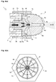
Fig. 3] Fig. 3(a) is a lateral enlarged view illustrating a tip end of the urea solution spray nozzle inFig. 2 , andFig. 3(b) is an A arrow view of the urea solution spray nozzle inFig. 3(a) . - [
Fig. 4] Fig. 4(a) is a cross-sectional view illustrating a state where urea solution is supplied from the urea solution spray nozzle of the exhaust purification device according to the embodiment of the present embodiment to the interior of an exhaust pipe, andFig. 4(b) is a B arrow view of the urea solution spray nozzle inFig. 4(a) . - Hereinafter, an
exhaust purification device 100 of a marine engine according to an embodiment of the present invention will be described referring to theFigs. 1 and2 . It is noted that, in the present embodiment, "upstream side" represents the upstream side of the flow direction of a fluid, and "downstream side" represents the downstream side of the flow direction of the fluid. The present embodiment is configured such that theexhaust purification device 100 is provided with respect to one engine (for example, a main engine or auxiliaries for a marine engine), but not limited to this. When a plurality of engines (for example, auxiliaries for the marine engine) are arranged, it may be configured that one exhaust purification device purifies the exhaust from the plurality of engines en masse, or that the exhaust purification device is provided for each engine. - Firstly, the
exhaust pipe 21 of anengine 20 will be described. As illustrated inFig. 1 , theexhaust pipe 21 discharges the exhaust from theengine 20 to the outside (atmosphere). Theexhaust purification device 100 is provided in theexhaust pipe 21. Also, in theexhaust pipe 21, abranch pipe 21c andexhaust switching valves exhaust purification device 100. Thebranch pipe 21a is connected to theexhaust pipe 21. Theexhaust switching valve 21b is arranged on the upstream side of theexhaust purification device 100 and in the interior of theexhaust pipe 21 on the downstream side of thebranch pipe 21 a. Theexhaust switching valve 21c is arranged in the interior of thebranch pipe 21c. - The
exhaust switching valves exhaust switching valves exhaust switching valve 21b is in an open state, theexhaust switching valve 21c is brought in a closed state, whereas when theexhaust switching valve 21b is in a closed state, theexhaust switching valve 21c is brought in an open state. Accordingly, when theexhaust switching valves 21b is in an open state, and theexhaust switching valve 21c is in a closed state, a path through which the exhaust is supplied to theexhaust purification device 100 is constituted in the exhaust pipe 21 (state inFig. 1 ). In contrast, when theexhaust switching valve 21b is in a closed state, and theexhaust switching valve 21c is in an open state, a path through which the exhaust is not purified with theexhaust purification device 100 but discharged through thebranch pipe 21c to the outside (atmosphere) is constituted in theexhaust pipe 21. - Also, as another embodiment, it may be configured that an exhaust switching valve for selectively bringing any one of the
exhaust pipe 21 and thebranch pipe 21c into a closed state is provided at the connection portion of thebranch pipe 21c. When thebranch pipe 21c is in a closed state, the path through which the exhaust is supplied to theexhaust purification device 100 is constituted in theexhaust pipe 21. In contrast, when theexhaust pipe 21 is in a closed state, the path through which the exhaust is not purified with theexhaust purification device 100 but discharged through thebranch pipe 21c to the outside (atmosphere) is constituted in theexhaust pipe 21. - Next, the
exhaust purification device 100 will be described. Theexhaust purification device 100 purifies the exhaust from theengine 20. Theexhaust purification device 100 includes a ureasolution spray nozzle 1, a pressurized air supply pump (compressor) 6, a pressurizedair valve 8, a urea solution supply pump 9, aswitching valve 11, anNOx detection unit 12, acontroller 13, a firstsupply flow path 14, a secondsupply flow path 15, anNOx catalyst 18, and the like. - The urea
solution spray nozzle 1 supplies the urea solution to the interior of theexhaust pipe 21. The ureasolution spray nozzle 1 is provided on the downstream side of theexhaust switching valve 21b in theexhaust pipe 21. The ureasolution spray nozzle 1 is constituted of a tubular member and provided in such a manner that the one side thereof (downstream side) is inserted from the exterior to the interior of theexhaust pipe 21. The ureasolution spray nozzle 1 includes adouble pipe 2, aliquid nozzle 3, anair nozzle 4, anut 5, and the like (seeFig. 2 ). - The pressurized air supply pump (compressor) 6 supplies pressurized air to an
air tank 7. The pressurizedair supply pump 6 pressurizes (compresses) the air and supplies the pressurized air. When the pressure of theair tank 7 falls below predetermined pressure, the pressurizedair supply pump 6 supplies the air to theair tank 7, and when the pressure of theair tank 7 reaches predetermined pressure, the pressurizedair supply pump 6 stops. - The pressurized
air valve 8 communicates with or blocks a flow path for the pressurized air. The pressurizedair valve 8 is provided in the secondsupply flow path 15. Thepressurized air valve 8 slides a spool, thereby switching a position V and a position W. Regarding thepressurized air valve 8, when the spool is in a state of being at the position V, the secondsupply flow path 15 is blocked. Accordingly, the pressurized air is not supplied to the ureasolution spray nozzle 1. Regarding thepressurized air valve 8, when the spool is in a state of being at the position W, the secondsupply flow path 15 is communicated. Accordingly, the pressurized air is supplied to the ureasolution spray nozzle 1. - The urea solution supply pump 9 supplies the urea solution to the urea
solution spray nozzle 1. The urea solution supply pump 9 is provided in the firstsupply flow path 14. The urea solution supply pump 9 supplies the urea solution in aurea solution tank 10 to the ureasolution spray nozzle 1 at a predetermined flow rate via the firstsupply flow path 14. - The switching
valve 11 switches the flow paths of the urea solution. The switchingvalve 11 is provided on the downstream side of the urea solution supply pump 9 of the firstsupply flow path 14. Adrain pot 16 is connected to the switchingvalve 11 via aflow path 15a. The switchingvalve 11 slides a spool, thereby switching a position X and a position Y. Regarding the switchingvalve 11, when the spool is in a state of being at the position X, the firstsupply flow path 14 is blocked, and the ureasolution spray nozzle 1 and thedrain pot 16 are communicated. Regarding the switchingvalve 11, when the spool is in a state of being at the position Y, the firstsupply flow path 14 is communicated. Accordingly, the urea solution is supplied to the ureasolution spray nozzle 1. - The
NOx detection unit 12 detects NOx emission included in the exhaust of theengine 20. TheNOx detection unit 12 is constituted of an NOx sensor and the like and arranged at a midway portion of theexhaust pipe 21 and on the upstream side with respect to theNOx catalyst 18. - The
controller 13 controls the urea solution supply pump 9, the switchingvalve 11, thepressurized air valve 8, theexhaust switching valves valve 11, thepressurized air valve 8, theexhaust switching valves controller 13. Thecontroller 13 may be configured such that a CPU, a ROM, a RAM, a HDD, and the like are connected via a bus or may be configured to be made up of one-chip LDI and the like. Also, thecontroller 13 may be integrally configured with anECU 22 for controlling theengine 20. - The
controller 13 is connected to theECU 22, thepressurized air valve 8, the urea solution supply pump 9, the switchingvalve 11, and theexhaust switching valves controller 13 is connected to a GPS (global positioning system)device 23. - The
controller 13 can obtain various pieces of information on theengine 20 from theECU 22 respectively. Thecontroller 13 is connected to theNOx detection unit 12 and can obtain the NOx emission detected by theNOx detection unit 12. Thecontroller 13 is connected to the GPS (global positioning system)device 23 and can obtain a present position of theexhaust purification device 100, which is detected by theGPS device 23. Also, thecontroller 13 can control thepressurized air valve 8, the urea solution supply pump 9, the switchingvalve 11, and theexhaust switching valves - The
NOx catalyst 18 facilitates the reduction reaction of NOx. TheNOx catalyst 18 is arranged in the interior of theexhaust pipe 21 and on the downstream side with respect to the ureasolution spray nozzle 1. TheNOx catalyst 18 facilitates reaction in which NOx included in the exhaust is reduced to nitrogen and water with ammonia generated by pyrolyzing and hydrolyzing the urea solution. - Regarding the
exhaust purification device 100 constituted in the aforementioned manner, for example, when theexhaust purification device 100 is mounted on a vessel, thecontrol device 13 obtains a present position detected by theGPS device 23 and determines whether or not the present position is in an exhaust regulation area based on the exhaust regulation area map M1. When thecontrol device 13 determines that the present position is in the exhaust regulation area, thecontrol device 13 controls theexhaust switching valve 21b to be in an open state, and controls theexhaust switching valve 21c to be in a closed state. That is, after being purified by theexhaust purification device 100, the exhaust is discharged to the outside. When thecontrol device 13 determines that the present position is not in the exhaust regulation area, thecontrol device 13 controls theexhaust switching valve 21b to be in a closed state, and controls theexhaust switching valve 21c to be in an open state. That is, the exhaust is not purified by the exhaust purification device but discharged to the outside through thebranch pipe 21a. It is noted that thecontrol device 13 can obtain an open/close signal of theexhaust switching valves exhaust switching valves - Next, the urea
solution spray nozzle 1 of an intermixing type will be specifically described referring toFigs. 2 and3 . It is noted that the type of the ureasolution spray nozzle 1 is not limited to the present embodiment but the ureasolution spray nozzle 1 of a non-premixing type may be employed. - As illustrated in
Fig. 2 , the ureasolution spray nozzle 1 includes thedouble pipe 2, theliquid nozzle 3, theair nozzle 4, and thenut 5. - The
double pipe 2 is a main constituent member of the ureasolution spray nozzle 1 and constitutes a path of the urea solution and a path of the pressurized air. Thedouble pipe 2 is arranged in such a manner that the downstream side thereof is positioned in the interior of theexhaust pipe 21, and the upstream side thereof is positioned in the exterior of theexhaust pipe 21. The end portion on the downstream side of thedouble pipe 2 is arranged on the upstream side of theNOx catalyst 18 arranged in the interior of theexhaust pipe 21. - The
double pipe 2 is constituted of anouter pipe 2b and aninner pipe 2a arranged in the interior of theouter pipe 2b. A ureasolution flow path 2c, which is a flow path of the urea solution, is constituted in theinner pipe 2a. Agas flow path 2d, which is a flow path of the pressurized air, is constituted in a gap between theinner pipe 2a and theouter pipe 2b. A connection portion not illustrated but connectible with theexhaust pipe 21 in a watertight manner is constituted in a midway portion on the outer side of theouter pipe 2b. Afemale screw portion 2e and amale screw portion 2f are formed at an end portion on the downstream side of theinner pipe 2a and at an end portion on the downstream side of theouter pipe 2b. A ureasolution supply port 2g communicated with the ureasolution flow path 2c and agas supply port 2h communicated with thegas flow path 2d are constituted at an end portion on the upstream side of thedouble pipe 2. - The
liquid nozzle 3 injects the urea solution. Theliquid nozzle 3 is formed of an approximately cylindrical member and arranged on the downstream side of thedouble pipe 2. The end portion on the downstream side of theliquid nozzle 3 is formed in an approximately conical shape centering on the shaft center portion thereof. An approximately cylindricalconvex portion 3a is formed in such a manner as to protrude in the axial direction at the center portion of the end portion on the downstream side. Amale screw portion 3b is formed in such a manner as to protrude in the axial direction at the end portion on the upstream side of theliquid nozzle 3. Furthermore, in the shaft center portion of theliquid nozzle 3, a ureasolution flow path 3c is formed from themale screw portion 3b to theconvex portion 3a in such a manner as to penetrate the whole of theliquid nozzle 3 in the axial direction. The ureasolution flow path 3c is reduced in diameter at the midway portion with respect to the downstream side and formed in such a manner that the inner diameter of the end portion on the downstream side of the ureasolution flow path 3c is made smaller than the inner diameter of the end portion on the upstream side of the ureasolution flow path 3c. - Regarding the
liquid nozzle 3, themale screw portion 3b is threadedly engaged with thefemale screw portion 2e of thedouble pipe 2. Accordingly, thedouble pipe 2 and theliquid nozzle 3 are connected, and the ureasolution flow path 3c and the ureasolution flow path 2c of thedouble pipe 2 are communicated. Thus, the urea solution is configured to be supplied from the ureasolution flow path 2c of thedouble pipe 2 to the ureasolution flow path 3c. - The
air nozzle 4 injects the atomized urea solution. Theair nozzle 4 is formed of an approximately cylindrical member. Theair nozzle 4 is arranged on the downstream side of theliquid nozzle 3 in such a manner that an upstream-side end thereof is abutted to the end portion of thedouble pipe 2 on the downstream side. In the shaft center portion of theair nozzle 4, a hole that includes an approximately conical reduced-diameter portion, whose diameter is reduced from the midway portion to the downstream side, is formed in such a manner as to penetrate theair nozzle 4 from the upstream-side end to the downstream-side end thereof. The end portion of the hole on the upstream side is formed in such a manner as to have an inner diameter to the extent that even when the end portion of theliquid nozzle 3 on the downstream side is inserted, a space through which the compressed air can pass is constituted. A mixingflow path 4d of the urea solution is formed at the shaft center portion of the reduced-diameter-side end of the reduced-diameter portion. Then, aninjection port 4f, which is an opening portion of the mixingflow path 4d, is formed at the end portion of theair nozzle 4 on the downstream side. - A
flange portion 4a is formed on the lateral surface of the end portion on the upstream side of theair nozzle 4. The downstream side of theair nozzle 4 is formed in an approximately shell shape in which theinjection port 4f is positioned as an apex. Specifically, as illustrated inFig. 3 , on the lateral surface (surface) on the downstream side of theair nozzle 4, asurface 4b made up of a curved surface, on which a distance from the mixingflow path 4d is reduced as being in close proximity to theinjection port 4f, is formed in a predetermined range L in a side view (in the lateral direction of an axial line C of the air nozzle 4) from theinjection port 4f. Furthermore, regarding theair nozzle 4, asurface 4c is formed in a predetermined range D centering on theinjection port 4f in a front view (in the direction of the axial line C of the air nozzle 4). Thesurface 4c is formed in such a manner that the outline in the predetermined range D in a side view of theair nozzle 4 forms a constant angle θ with respect to the axial line C. That is, the downstream side of theair nozzle 4 is formed in an approximately truncated cone, centering on theinjection port 4f. Accordingly, theair nozzle 4 has an inclined plane that is contiguous to theinjection port 4f and has a constant tilted angle θ in such a manner as to surround theinjection port 4f. - A water-
repellent coating layer 4h is formed on thesurface 4b and thesurface 4c of theair nozzle 4. The water-repellent coating layer 4h suppresses the adhesion of the urea solution, which is liquid. The water-repellent coating layer 4h is constituted of a ceramic coating layer that can be used in the exhaust having a temperature approximately ranging from 300 to 350 Celsius degrees. The exhaust temperature substantially varies depending on a state of load of theengine 20. Accordingly, regarding the water-repellent coating layer 4h, a ceramic coating layer is suitable that has higher thermal resistance than that of fluorine coating, which is general thermal resistant coating whose thermal resistant temperature is approximately 250 Celsius degrees. Accordingly, theair nozzle 4 can easily remove the urea solution from the surface thereof. - As illustrated in
Fig. 2 , theair nozzle 4 is connected to thedouble pipe 2 by means of thenut 5. The end portion on the downstream side of theliquid nozzle 3 is inserted into the hole on the upstream side of theair nozzle 4. In this time, a gap is formed between the hole of theair nozzle 4 and theliquid nozzle 3. The gap is constituted as agas flow path 4e in such a manner as to communicate with thegas flow path 2d and the mixingflow path 4d of thedouble pipe 2. Thus, the urea solution is supplied from the ureasolution flow path 3c of theliquid nozzle 3 to themixing flow path 4d, and the pressurized air is supplied from thegas flow path 4e to themixing flow path 4d. That is, theair nozzle 4 is threadedly engaged with thedouble pipe 2, so that it is constituted that the urea solution can be injected from theinjection port 4f. - One or more
branch flow paths 4g are formed in theair nozzle 4 in such a manner as to communicate with the hole of theair nozzle 4 from the lateral surface thereof. That is, thebranch flow paths 4g are formed in such a manner as to communicate from the lateral surface of theair nozzle 4 to thegas flow path 4e. When the pressurized air is supplied to thegas flow path 4e, part of the pressurized air is discharged to the lateral surface of theair nozzle 4 via thebranch flow paths 4g. Regarding thebranch flow paths 4g, the number ofbranch flow paths 4g or the inner diameter of the flow path is determined in accordance with the amount of pressurized air discharged to the lateral surface of theair nozzle 4. - The
double pipe 2 and theair nozzle 4 are fastened with thenut 5. A steppedportion 5a engaged with theflange portion 4a of theair nozzle 4 is formed in the inner diameter of thenut 5. Afemale screw portion 5b that is threadedly engaged with themale screw portion 2f of thedouble pipe 2 is formed on the upstream side of the steppedportion 5a. The downstream side of the steppedportion 5a is formed in such a manner as to have an inner diameter to the extent that theair nozzle 4 can be inserted without a gap. Also, an expanded-diameter portion is formed on the downstream side of the steppedportion 5a and at a section facing thebranch flow path 4g of theair nozzle 4. The downstream side of the expanded-diameter portion is formed in such a manner as to have an inner diameter that is slightly larger than the outer diameter of theair nozzle 4. - The
nut 5 is fixed such that the steppedportion 5a is engaged with theflange portion 4a of theair nozzle 4, and that thefemale screw portion 5b is threadedly engaged with themale screw portion 2f of thedouble pipe 2. Accordingly, the end portion on the upstream side of theair nozzle 4 is abutted and fixed on the end portion on the downstream side of thedouble pipe 2. In this time, aspace 5c, in which gas from the expanded-diameter portion of thenut 5 and the lateral surface of theair nozzle 4 stays, is constituted. Consequently, thespace 5c is constituted in such a manner that the pressurized air can be supplied via thebranch flow paths 4g of theair nozzle 4. - As illustrated in
Figs. 2 and3 , aslit 5d is constituted between theair nozzle 4 and thenut 5 on the downstream side with respect to thespace 5c. That is, theslit 5d is constituted along the lateral surface in such a manner as to surround theair nozzle 4. Furthermore, theslit 5d is communicated with thespace 5c. That is, the pressurized air supplied to thespace 5c is constituted such that the pressurized air can be discharged to the downstream side of thespace 5c, which is disposed in the same direction as the injection direction of the urea solution, from theslit 5d along the lateral surface of theair nozzle 4. In this manner, theslit 5d, which is a lateral ejection port from which the pressurized air is discharged, is constituted on the lateral surface of theair nozzle 4. - As described above, the urea
solution spray nozzle 1 is configured to include theliquid nozzle 3 that injects the urea solution to the end portion on one side (downstream side) and theair nozzle 4 and inject the urea solution to theNOx catalyst 18. It is noted that, regarding the constitution of the ureasolution spray nozzle 1, in the present embodiment, the ureasolution flow path 3c, thegas flow path 4e, and the mixingflow path 4d are constituted of theliquid nozzle 3 and theair nozzle 4, but not particularly limited to these. The ureasolution flow path 3c, thegas flow path 4e, and the mixingflow path 4d only need to be constituted respectively. - Hereinafter, the operational mode of the urea
solution spray nozzle 1 will be described referring toFigs. 1 ,2 , and4 . - As illustrated in
Fig. 1 , when the supply (injection) of the urea solution to the interior of theexhaust pipe 21 is started, thecontroller 13 sets the switchingvalve 11 to the position Y, thereby supplying the urea solution to the ureasolution supply port 2g of the urea solution spray nozzle 1 (double pipe 2). As illustrated inFigs. 2 and4(a) , the urea solution, as represented in black-painted arrows inFig. 4(a) , is injected under predetermined pressure from theconvex portion 3a of theliquid nozzle 3 to themixing flow path 4d of theair nozzle 4 via the ureasolution flow path 2c of thedouble pipe 2 and the ureasolution flow path 3c of theliquid nozzle 3. - In this state, as illustrated in
Fig. 1 , thecontroller 13 sets thepressurized air valve 8 to the position W, thereby supplying the pressurized air to thegas supply port 2h of the urea solution spray nozzle 1 (double pipe 2). As illustrated inFigs. 2 and4(a) , the pressurized air, as represented in void arrows inFig. 4(a) , is injected under predetermined pressure to themixing flow path 4d of theair nozzle 4 via thegas flow path 2d of thedouble pipe 2 and thegas flow path 4e of theair nozzle 4. As a result, the urea solution collides with the pressurized air in the interior of the mixingflow path 4d of theair nozzle 4, and the urea solution is atomized and injected from theinjection port 4f of theair nozzle 4. - Part of the pressurized air supplied to the
gas flow path 4e of theair nozzle 4 is supplied to thespace 5c via thebranch flow paths 4g. The pressurized air supplied to thespace 5c is discharged under uniform pressure from theslit 5d to the downstream side (the side of theinjection port 4f) of theair nozzle 4. The pressurized air discharged from theslit 5d advances in such a manner as to wrap theair nozzle 4 along the lateral surface of theair nozzle 4 owing to the viscosity of the pressurized air. The pressurized air advances on the surface of theair nozzle 4 along thesurface 4b and thesurface 4c, which are the lateral surfaces of theair nozzle 4 formed in a shell shape, and reaches theinjection port 4f. Accordingly, even when the urea solution injected from theinjection port 4f comes close to thesurface 4b and thesurface 4c of theair nozzle 4, the urea solution is blown away by the pressurized air. Also, the urea solution adhered to thesurface 4b and thesurface 4c of theair nozzle 4 is easily blown away by the pressurized air by dint of the effect of the water-repellent coating layer 4h. - As illustrated in
Fig. 1 , when the supply (injection) of the urea solution to the interior of theexhaust pipe 21 is stopped, thecontroller 13 sets the position of the switchingvalve 11 to the position X, thereby stopping the supply of the urea solution to the ureasolution supply port 2g of the urea solution spray nozzle 1 (double pipe 2). Along with this, the ureasolution supply port 2g of thedouble pipe 2 is opened to the atmosphere via the firstsupply flow path 14 and the switchingvalve 11. Regarding theair nozzle 4, even when the urea solution is adhered to the surface of theair nozzle 4 after stoppage of the pressurized air from theslit 5d, the urea solution flows off the surface of theair nozzle 4 owing to the effect of the water-repellent coating layer 4h formed on thesurface 4b and thesurface 4c, which suppresses the adhesion of the urea solution. - Also, in a case where the urea
solution spray nozzle 1 is arranged in such a manner that theinjection port 4f of theair nozzle 4 is directed upward, even when the urea solution is adhered to the periphery of theinjection port 4f of theair nozzle 4, the urea solution flows downward owing to the inclination of thesurface 4c formed in such a manner as to surround theinjection port 4f, in addition to the effect of the water-repellent coating layer 4h formed on thesurface 4b and thesurface 4c, which suppresses the adhesion of the urea solution. - As described above, the urea solution adhered to the lateral surface (surface) of the urea
solution spray nozzle 1 is easily eliminated by use of the water-repellent effect of the tip end of theair nozzle 4 and the ejection force of the pressurized air, which is the discharged gas along thesurface 4b and thesurface 4c of theair nozzle 4. Accordingly, the deposit and growth of the urea in theair nozzle 4 can be suppressed. - Also, the
surface 4c that includes the inclined plane in the vicinity of theinjection port 4f of the ureasolution spray nozzle 1 is formed, so that the urea solution adhered to the vicinity of theinjection port 4f is easily eliminated. Accordingly, the deposit and growth of the urea in theair nozzle 4 can be suppressed. - Also, even when the
air nozzle 4 is arranged in the high-temperature exhaust, the water-repellent effect can be maintained. Accordingly, the deposit and growth of the urea in theair nozzle 4 can be suppressed. - The present invention can be applied to the technology of the urea solution spray nozzle of the exhaust purification device.
-
- 1
- Urea solution spray nozzle
- 2c
- Urea solution flow path
- 3c
- Urea solution flow path
- 2d
- Gas flow path
- 4c
- Surface
- 4d
- Surface
- 4e
- Gas flow path
- 4f
- Injection port
- 5d
- Slit
Claims (3)
- A urea solution spray nozzle in which a urea solution flow path and a gas flow path are constituted, and urea solution and gas are mixed and injected from an injection port,
wherein a lateral ejection port is constituted in such a manner that the gas is ejected in a same direction as an injection direction of the urea solution along a surface of the urea solution spray nozzle, and
wherein a water-repellent coating layer is formed on the surface of the urea solution spray nozzle. - The urea solution spray nozzle according to claim 1,
wherein it is formed in such a manner that a distance from a flow path, in which the gas and the urea solution are mixed, to the surface is reduced as being in close proximity to the injection port, and
wherein an outline of the urea solution spray nozzle in a side view in a predetermined range from the injection port is configured to form a constant angle with respect to the injection direction of the urea solution. - The urea solution spray nozzle according to claim 1 or 2,
wherein the water-repellent coating layer is a ceramic coating layer.
Applications Claiming Priority (2)
| Application Number | Priority Date | Filing Date | Title |
|---|---|---|---|
| JP2013118011A JP6166103B2 (en) | 2013-06-04 | 2013-06-04 | Urea water injection nozzle |
| PCT/JP2014/064321 WO2014196456A1 (en) | 2013-06-04 | 2014-05-29 | Urea solution spray nozzle |
Publications (3)
| Publication Number | Publication Date |
|---|---|
| EP3006687A1 true EP3006687A1 (en) | 2016-04-13 |
| EP3006687A4 EP3006687A4 (en) | 2017-05-24 |
| EP3006687B1 EP3006687B1 (en) | 2018-08-01 |
Family
ID=52008102
Family Applications (1)
| Application Number | Title | Priority Date | Filing Date |
|---|---|---|---|
| EP14808320.7A Not-in-force EP3006687B1 (en) | 2013-06-04 | 2014-05-29 | Urea solution spray nozzle |
Country Status (7)
| Country | Link |
|---|---|
| US (1) | US10487758B2 (en) |
| EP (1) | EP3006687B1 (en) |
| JP (1) | JP6166103B2 (en) |
| KR (1) | KR101740580B1 (en) |
| CN (1) | CN105247181B (en) |
| DK (1) | DK3006687T3 (en) |
| WO (1) | WO2014196456A1 (en) |
Families Citing this family (15)
| Publication number | Priority date | Publication date | Assignee | Title |
|---|---|---|---|---|
| JP6392177B2 (en) * | 2015-06-29 | 2018-09-19 | 株式会社パウレック | Spray nozzle and cleaning method thereof |
| CN109838295B (en) * | 2017-11-29 | 2022-12-02 | 博世动力总成有限公司 | Tail gas aftertreatment system of diesel engine and pressure fluctuation amplitude determination method |
| JP6954109B2 (en) * | 2017-12-27 | 2021-10-27 | いすゞ自動車株式会社 | Urea water injection device |
| US10953373B2 (en) * | 2018-11-15 | 2021-03-23 | Caterpillar Inc. | Reductant nozzle with radial air injection |
| US11534728B2 (en) | 2018-11-15 | 2022-12-27 | Caterpillar Inc. | Reductant nozzle with helical channel design |
| US10888885B2 (en) | 2018-11-15 | 2021-01-12 | Caterpillar Inc. | Reductant nozzle with swirling spray pattern |
| US10894237B2 (en) | 2018-11-15 | 2021-01-19 | Caterpillar Inc. | Reductant nozzle with concave impinging surface |
| US10766044B2 (en) * | 2018-11-21 | 2020-09-08 | Caterpillar Inc. | Channeled reductant mixing device |
| JP2020176602A (en) * | 2019-04-22 | 2020-10-29 | 株式会社デンソー | Fluid injection device and fluid injection system |
| KR102596285B1 (en) | 2020-03-30 | 2023-11-01 | 세메스 주식회사 | Tower Lift, Driving Method for tower lift and Machine readable medium |
| CN111889247A (en) * | 2020-08-14 | 2020-11-06 | 广西励领农业科技有限公司 | Sprayer with novel spray head structure |
| CN112855313A (en) * | 2021-03-29 | 2021-05-28 | 河北亚大汽车塑料制品有限公司 | Connection process of automobile urea pipe |
| US20220364490A1 (en) * | 2021-05-11 | 2022-11-17 | Caterpillar Inc. | Exhaust fluid injector assembly |
| DE102022120146A1 (en) * | 2022-08-10 | 2024-02-15 | Glatt Gesellschaft Mit Beschränkter Haftung | Nozzle arrangement |
| JP2025082365A (en) | 2023-11-17 | 2025-05-29 | ヤンマーホールディングス株式会社 | Exhaust emission control device |
Family Cites Families (33)
| Publication number | Priority date | Publication date | Assignee | Title |
|---|---|---|---|---|
| JPS5141693B1 (en) * | 1971-05-24 | 1976-11-11 | ||
| US4036434A (en) * | 1974-07-15 | 1977-07-19 | Aerojet-General Corporation | Fluid delivery nozzle with fluid purged face |
| US4080099A (en) * | 1976-05-02 | 1978-03-21 | Brunswick Corporation | Propeller |
| US4241656A (en) * | 1978-11-17 | 1980-12-30 | Smith R. P. M. Corporation | Self-cleaning nozzle for lithographic printing dampeners |
| CA1159356A (en) * | 1979-10-25 | 1983-12-27 | Kurt Skoog | Method and device for producing microdroplets of fluid |
| JPS57194064A (en) * | 1981-05-22 | 1982-11-29 | Alloy Koki Kk | Spraying device suitable for spraying of high viscosity liquid |
| JPH04101059A (en) * | 1990-08-13 | 1992-04-02 | Japan Electron Control Syst Co Ltd | Assist air type fuel injector |
| JPH09310660A (en) * | 1996-05-21 | 1997-12-02 | Mitsubishi Electric Corp | Electromagnetic fuel injection valve |
| DE19961947A1 (en) * | 1999-12-22 | 2001-06-28 | Bosch Gmbh Robert | Apparatus, for producing reductant-air mixture, has devices for subjecting air to pressure such that it flows through air feed channel at speed of sound |
| DE19963394A1 (en) * | 1999-12-28 | 2001-07-05 | Bosch Gmbh Robert | Aerosol generator for exhaust processing in IC engines has secondary air supply elements for effective fluid-air-mixture generation and quicker aerosol transport |
| DE10040571A1 (en) * | 2000-08-18 | 2002-02-28 | Bosch Gmbh Robert | Device for producing a reducing agent-air mixture |
| JP3888519B2 (en) * | 2001-09-12 | 2007-03-07 | 株式会社デンソー | Exhaust purification device |
| JP3657922B2 (en) * | 2002-05-10 | 2005-06-08 | 株式会社東京機械製作所 | Spray dampening water supply device |
| US20050284957A1 (en) * | 2002-09-23 | 2005-12-29 | Spraying Systems Co. | External mix air atomizing spray nozzle assembly |
| DE60332664D1 (en) * | 2003-12-23 | 2010-07-01 | Yara Int Asa | SPRAYING DEVICE AND METHOD FOR SPATIAL LAYER GRANULATION |
| US7621465B2 (en) * | 2005-11-10 | 2009-11-24 | Nordson Corporation | Air annulus cut off nozzle to reduce stringing and method |
| DE102006009147A1 (en) * | 2006-02-24 | 2007-08-30 | Wurz, Dieter, Prof. Dr.-Ing. | Dual nozzle has mixing chamber, and ring is arranged by secondary air nozzles around mouth of main nozzle |
| JP2008019773A (en) * | 2006-07-12 | 2008-01-31 | Toyota Motor Corp | Fuel injection valve for internal combustion engine |
| EP2538048B1 (en) * | 2007-03-30 | 2015-03-04 | Continental Automotive Systems US, Inc. | Reductant delivery unit for selective catalytic reduction |
| JP2009041502A (en) * | 2007-08-10 | 2009-02-26 | Hino Motors Ltd | Urea addition nozzle |
| DE102007044272A1 (en) * | 2007-09-17 | 2009-04-02 | Wurz, Dieter, Prof. Dr.-Ing. | Multi-hole or bundle head nozzle with and without compressed air support |
| DE102009037828A1 (en) * | 2008-11-11 | 2010-05-20 | Wurz, Dieter, Prof. Dr. | Two-fluid nozzle, bundling nozzle and method for atomizing fluids |
| US9631528B2 (en) * | 2009-09-03 | 2017-04-25 | Clean Emissions Technologies, Inc. | Vehicle reduced emission deployment |
| JP5010662B2 (en) * | 2009-10-08 | 2012-08-29 | ヤンマー株式会社 | Exhaust purification device |
| US8839611B2 (en) * | 2010-05-05 | 2014-09-23 | Cummins Power Generation Ip, Inc | Exhaust injection muffler |
| US8756921B2 (en) * | 2011-01-10 | 2014-06-24 | Paccar Inc | Reductant delivery device |
| DE102011003356A1 (en) * | 2011-01-31 | 2012-08-02 | Robert Bosch Gmbh | Apparatus for delivering reducing agent into exhaust gas passage of internal combustion engine, has gas blowing element that blows out gas to deflect reducing agent introduced from spray opening toward central axis of exhaust gas passage |
| DE102011010641A1 (en) * | 2011-02-09 | 2012-08-09 | Emitec France S.A.S | Injector for a urea-water solution |
| US8985088B2 (en) * | 2012-07-31 | 2015-03-24 | General Electric Company | Systems and methods for controlling exhaust gas recirculation |
| DE102011107609A1 (en) * | 2011-06-30 | 2013-01-03 | Albonair Gmbh | Outside mixing reducer injector nozzle for injecting reducing agent into exhaust system of engine, has nozzle orifices by which reducing agent and compressed air or propellant gas are emerged and atomized so that aerosol is formed |
| US20130261939A1 (en) * | 2012-04-01 | 2013-10-03 | Zonar Systems, Inc. | Method and apparatus for matching vehicle ecu programming to current vehicle operating conditions |
| JP6108427B2 (en) | 2012-06-21 | 2017-04-05 | ヤンマー株式会社 | Urea water injection nozzle |
| CN105338937B (en) * | 2013-06-28 | 2019-05-14 | 大王制纸株式会社 | absorbent articles |
-
2013
- 2013-06-04 JP JP2013118011A patent/JP6166103B2/en not_active Expired - Fee Related
-
2014
- 2014-05-29 EP EP14808320.7A patent/EP3006687B1/en not_active Not-in-force
- 2014-05-29 WO PCT/JP2014/064321 patent/WO2014196456A1/en not_active Ceased
- 2014-05-29 US US14/895,325 patent/US10487758B2/en active Active
- 2014-05-29 KR KR1020157035976A patent/KR101740580B1/en not_active Expired - Fee Related
- 2014-05-29 CN CN201480031314.6A patent/CN105247181B/en not_active Expired - Fee Related
- 2014-05-29 DK DK14808320.7T patent/DK3006687T3/en active
Non-Patent Citations (1)
| Title |
|---|
| See references of WO2014196456A1 * |
Also Published As
| Publication number | Publication date |
|---|---|
| KR101740580B1 (en) | 2017-06-08 |
| JP2014234793A (en) | 2014-12-15 |
| DK3006687T3 (en) | 2018-10-29 |
| CN105247181B (en) | 2018-04-03 |
| US20160108838A1 (en) | 2016-04-21 |
| KR20160008642A (en) | 2016-01-22 |
| CN105247181A (en) | 2016-01-13 |
| EP3006687A4 (en) | 2017-05-24 |
| JP6166103B2 (en) | 2017-07-19 |
| US10487758B2 (en) | 2019-11-26 |
| WO2014196456A1 (en) | 2014-12-11 |
| EP3006687B1 (en) | 2018-08-01 |
Similar Documents
| Publication | Publication Date | Title |
|---|---|---|
| EP3006687B1 (en) | Urea solution spray nozzle | |
| US9279355B2 (en) | Urea solution injection nozzle | |
| US8438839B2 (en) | Exhaust gas stream vortex breaker | |
| KR100974982B1 (en) | Engine exhaust purifier | |
| JP5010662B2 (en) | Exhaust purification device | |
| KR101831750B1 (en) | Exhaust-gas purification device | |
| US20150101313A1 (en) | Diesel Exhaust Fluid Deposit Mitigation | |
| KR101809186B1 (en) | Engine with supercharger | |
| US9334775B2 (en) | Water injection exhaust treatment system | |
| JP2014005745A (en) | Urea water injection device | |
| JP2010090836A (en) | Urea water supply equipment | |
| SE525601C2 (en) | Equipment is for supply with heating of reduction medium from tank to exhaust gas conduit of internal combustion engine | |
| US20150345354A1 (en) | Exhaust aftertreatement system injector and control | |
| JP2016098714A (en) | Urea water injection system of internal combustion engine, internal combustion engine, and urea water injection method of internal combustion engine | |
| KR20230129978A (en) | Exhaust purification devices and engines | |
| JP2016196821A (en) | Reducing agent supply device | |
| JP2008050964A (en) | Exhaust emission control device |
Legal Events
| Date | Code | Title | Description |
|---|---|---|---|
| PUAI | Public reference made under article 153(3) epc to a published international application that has entered the european phase |
Free format text: ORIGINAL CODE: 0009012 |
|
| 17P | Request for examination filed |
Effective date: 20160104 |
|
| AK | Designated contracting states |
Kind code of ref document: A1 Designated state(s): AL AT BE BG CH CY CZ DE DK EE ES FI FR GB GR HR HU IE IS IT LI LT LU LV MC MK MT NL NO PL PT RO RS SE SI SK SM TR |
|
| AX | Request for extension of the european patent |
Extension state: BA ME |
|
| DAX | Request for extension of the european patent (deleted) | ||
| RIC1 | Information provided on ipc code assigned before grant |
Ipc: F01N 9/00 20060101ALI20170125BHEP Ipc: F01N 3/20 20060101ALI20170125BHEP Ipc: F01N 3/08 20060101AFI20170125BHEP |
|
| A4 | Supplementary search report drawn up and despatched |
Effective date: 20170426 |
|
| RIC1 | Information provided on ipc code assigned before grant |
Ipc: F01N 3/08 20060101AFI20170420BHEP Ipc: F01N 3/20 20060101ALI20170420BHEP Ipc: F01N 9/00 20060101ALI20170420BHEP |
|
| GRAP | Despatch of communication of intention to grant a patent |
Free format text: ORIGINAL CODE: EPIDOSNIGR1 |
|
| STAA | Information on the status of an ep patent application or granted ep patent |
Free format text: STATUS: GRANT OF PATENT IS INTENDED |
|
| INTG | Intention to grant announced |
Effective date: 20180223 |
|
| GRAS | Grant fee paid |
Free format text: ORIGINAL CODE: EPIDOSNIGR3 |
|
| GRAA | (expected) grant |
Free format text: ORIGINAL CODE: 0009210 |
|
| STAA | Information on the status of an ep patent application or granted ep patent |
Free format text: STATUS: THE PATENT HAS BEEN GRANTED |
|
| AK | Designated contracting states |
Kind code of ref document: B1 Designated state(s): AL AT BE BG CH CY CZ DE DK EE ES FI FR GB GR HR HU IE IS IT LI LT LU LV MC MK MT NL NO PL PT RO RS SE SI SK SM TR |
|
| REG | Reference to a national code |
Ref country code: GB Ref legal event code: FG4D |
|
| RIN1 | Information on inventor provided before grant (corrected) |
Inventor name: INOUE TSUYOSHI |
|
| REG | Reference to a national code |
Ref country code: CH Ref legal event code: EP Ref country code: AT Ref legal event code: REF Ref document number: 1024560 Country of ref document: AT Kind code of ref document: T Effective date: 20180815 |
|
| REG | Reference to a national code |
Ref country code: IE Ref legal event code: FG4D |
|
| REG | Reference to a national code |
Ref country code: DE Ref legal event code: R096 Ref document number: 602014029639 Country of ref document: DE |
|
| REG | Reference to a national code |
Ref country code: NL Ref legal event code: FP |
|
| REG | Reference to a national code |
Ref country code: DK Ref legal event code: T3 Effective date: 20181016 |
|
| REG | Reference to a national code |
Ref country code: LT Ref legal event code: MG4D |
|
| REG | Reference to a national code |
Ref country code: AT Ref legal event code: MK05 Ref document number: 1024560 Country of ref document: AT Kind code of ref document: T Effective date: 20180801 |
|
| PG25 | Lapsed in a contracting state [announced via postgrant information from national office to epo] |
Ref country code: RS Free format text: LAPSE BECAUSE OF FAILURE TO SUBMIT A TRANSLATION OF THE DESCRIPTION OR TO PAY THE FEE WITHIN THE PRESCRIBED TIME-LIMIT Effective date: 20180801 Ref country code: AT Free format text: LAPSE BECAUSE OF FAILURE TO SUBMIT A TRANSLATION OF THE DESCRIPTION OR TO PAY THE FEE WITHIN THE PRESCRIBED TIME-LIMIT Effective date: 20180801 Ref country code: NO Free format text: LAPSE BECAUSE OF FAILURE TO SUBMIT A TRANSLATION OF THE DESCRIPTION OR TO PAY THE FEE WITHIN THE PRESCRIBED TIME-LIMIT Effective date: 20181101 Ref country code: IS Free format text: LAPSE BECAUSE OF FAILURE TO SUBMIT A TRANSLATION OF THE DESCRIPTION OR TO PAY THE FEE WITHIN THE PRESCRIBED TIME-LIMIT Effective date: 20181201 Ref country code: GR Free format text: LAPSE BECAUSE OF FAILURE TO SUBMIT A TRANSLATION OF THE DESCRIPTION OR TO PAY THE FEE WITHIN THE PRESCRIBED TIME-LIMIT Effective date: 20181102 Ref country code: BG Free format text: LAPSE BECAUSE OF FAILURE TO SUBMIT A TRANSLATION OF THE DESCRIPTION OR TO PAY THE FEE WITHIN THE PRESCRIBED TIME-LIMIT Effective date: 20181101 Ref country code: SE Free format text: LAPSE BECAUSE OF FAILURE TO SUBMIT A TRANSLATION OF THE DESCRIPTION OR TO PAY THE FEE WITHIN THE PRESCRIBED TIME-LIMIT Effective date: 20180801 Ref country code: LT Free format text: LAPSE BECAUSE OF FAILURE TO SUBMIT A TRANSLATION OF THE DESCRIPTION OR TO PAY THE FEE WITHIN THE PRESCRIBED TIME-LIMIT Effective date: 20180801 Ref country code: PL Free format text: LAPSE BECAUSE OF FAILURE TO SUBMIT A TRANSLATION OF THE DESCRIPTION OR TO PAY THE FEE WITHIN THE PRESCRIBED TIME-LIMIT Effective date: 20180801 |
|
| PG25 | Lapsed in a contracting state [announced via postgrant information from national office to epo] |
Ref country code: AL Free format text: LAPSE BECAUSE OF FAILURE TO SUBMIT A TRANSLATION OF THE DESCRIPTION OR TO PAY THE FEE WITHIN THE PRESCRIBED TIME-LIMIT Effective date: 20180801 Ref country code: LV Free format text: LAPSE BECAUSE OF FAILURE TO SUBMIT A TRANSLATION OF THE DESCRIPTION OR TO PAY THE FEE WITHIN THE PRESCRIBED TIME-LIMIT Effective date: 20180801 Ref country code: HR Free format text: LAPSE BECAUSE OF FAILURE TO SUBMIT A TRANSLATION OF THE DESCRIPTION OR TO PAY THE FEE WITHIN THE PRESCRIBED TIME-LIMIT Effective date: 20180801 |
|
| PG25 | Lapsed in a contracting state [announced via postgrant information from national office to epo] |
Ref country code: ES Free format text: LAPSE BECAUSE OF FAILURE TO SUBMIT A TRANSLATION OF THE DESCRIPTION OR TO PAY THE FEE WITHIN THE PRESCRIBED TIME-LIMIT Effective date: 20180801 Ref country code: CZ Free format text: LAPSE BECAUSE OF FAILURE TO SUBMIT A TRANSLATION OF THE DESCRIPTION OR TO PAY THE FEE WITHIN THE PRESCRIBED TIME-LIMIT Effective date: 20180801 Ref country code: IT Free format text: LAPSE BECAUSE OF FAILURE TO SUBMIT A TRANSLATION OF THE DESCRIPTION OR TO PAY THE FEE WITHIN THE PRESCRIBED TIME-LIMIT Effective date: 20180801 Ref country code: RO Free format text: LAPSE BECAUSE OF FAILURE TO SUBMIT A TRANSLATION OF THE DESCRIPTION OR TO PAY THE FEE WITHIN THE PRESCRIBED TIME-LIMIT Effective date: 20180801 Ref country code: EE Free format text: LAPSE BECAUSE OF FAILURE TO SUBMIT A TRANSLATION OF THE DESCRIPTION OR TO PAY THE FEE WITHIN THE PRESCRIBED TIME-LIMIT Effective date: 20180801 |
|
| REG | Reference to a national code |
Ref country code: DE Ref legal event code: R097 Ref document number: 602014029639 Country of ref document: DE |
|
| PG25 | Lapsed in a contracting state [announced via postgrant information from national office to epo] |
Ref country code: SM Free format text: LAPSE BECAUSE OF FAILURE TO SUBMIT A TRANSLATION OF THE DESCRIPTION OR TO PAY THE FEE WITHIN THE PRESCRIBED TIME-LIMIT Effective date: 20180801 Ref country code: SK Free format text: LAPSE BECAUSE OF FAILURE TO SUBMIT A TRANSLATION OF THE DESCRIPTION OR TO PAY THE FEE WITHIN THE PRESCRIBED TIME-LIMIT Effective date: 20180801 |
|
| PLBE | No opposition filed within time limit |
Free format text: ORIGINAL CODE: 0009261 |
|
| STAA | Information on the status of an ep patent application or granted ep patent |
Free format text: STATUS: NO OPPOSITION FILED WITHIN TIME LIMIT |
|
| 26N | No opposition filed |
Effective date: 20190503 |
|
| PG25 | Lapsed in a contracting state [announced via postgrant information from national office to epo] |
Ref country code: SI Free format text: LAPSE BECAUSE OF FAILURE TO SUBMIT A TRANSLATION OF THE DESCRIPTION OR TO PAY THE FEE WITHIN THE PRESCRIBED TIME-LIMIT Effective date: 20180801 |
|
| REG | Reference to a national code |
Ref country code: CH Ref legal event code: PL |
|
| GBPC | Gb: european patent ceased through non-payment of renewal fee |
Effective date: 20190529 |
|
| PG25 | Lapsed in a contracting state [announced via postgrant information from national office to epo] |
Ref country code: MC Free format text: LAPSE BECAUSE OF FAILURE TO SUBMIT A TRANSLATION OF THE DESCRIPTION OR TO PAY THE FEE WITHIN THE PRESCRIBED TIME-LIMIT Effective date: 20180801 Ref country code: LI Free format text: LAPSE BECAUSE OF NON-PAYMENT OF DUE FEES Effective date: 20190531 Ref country code: CH Free format text: LAPSE BECAUSE OF NON-PAYMENT OF DUE FEES Effective date: 20190531 |
|
| REG | Reference to a national code |
Ref country code: BE Ref legal event code: MM Effective date: 20190531 |
|
| PG25 | Lapsed in a contracting state [announced via postgrant information from national office to epo] |
Ref country code: LU Free format text: LAPSE BECAUSE OF NON-PAYMENT OF DUE FEES Effective date: 20190529 |
|
| PG25 | Lapsed in a contracting state [announced via postgrant information from national office to epo] |
Ref country code: TR Free format text: LAPSE BECAUSE OF FAILURE TO SUBMIT A TRANSLATION OF THE DESCRIPTION OR TO PAY THE FEE WITHIN THE PRESCRIBED TIME-LIMIT Effective date: 20180801 |
|
| PG25 | Lapsed in a contracting state [announced via postgrant information from national office to epo] |
Ref country code: IE Free format text: LAPSE BECAUSE OF NON-PAYMENT OF DUE FEES Effective date: 20190529 Ref country code: GB Free format text: LAPSE BECAUSE OF NON-PAYMENT OF DUE FEES Effective date: 20190529 |
|
| PG25 | Lapsed in a contracting state [announced via postgrant information from national office to epo] |
Ref country code: BE Free format text: LAPSE BECAUSE OF NON-PAYMENT OF DUE FEES Effective date: 20190531 |
|
| PG25 | Lapsed in a contracting state [announced via postgrant information from national office to epo] |
Ref country code: PT Free format text: LAPSE BECAUSE OF FAILURE TO SUBMIT A TRANSLATION OF THE DESCRIPTION OR TO PAY THE FEE WITHIN THE PRESCRIBED TIME-LIMIT Effective date: 20181201 Ref country code: FR Free format text: LAPSE BECAUSE OF NON-PAYMENT OF DUE FEES Effective date: 20190531 |
|
| REG | Reference to a national code |
Ref country code: DE Ref legal event code: R082 Ref document number: 602014029639 Country of ref document: DE Representative=s name: JOSTARNDT PATENTANWALTS-AG, DE Ref country code: DE Ref legal event code: R081 Ref document number: 602014029639 Country of ref document: DE Owner name: JAPAN SHIP MACHINERY & EQUIPMENT ASSOCIATION, JP Free format text: FORMER OWNERS: JAPAN SHIP MACHINERY & EQUIPMENT ASSOCIATION, TOKYO, JP; YANMAR CO., LTD., OSAKA-SHI, JP Ref country code: DE Ref legal event code: R081 Ref document number: 602014029639 Country of ref document: DE Owner name: YANMAR POWER TECHNOLOGY CO., LTD., JP Free format text: FORMER OWNERS: JAPAN SHIP MACHINERY & EQUIPMENT ASSOCIATION, TOKYO, JP; YANMAR CO., LTD., OSAKA-SHI, JP |
|
| REG | Reference to a national code |
Ref country code: FI Ref legal event code: PCE Owner name: YANMAR POWER TECHNOLOGY CO., LTD. Ref country code: FI Ref legal event code: PCE Owner name: JAPAN SHIP MACHINERY & EQUIPMENT ASSOCIATION |
|
| REG | Reference to a national code |
Ref country code: NL Ref legal event code: HC Owner name: JAPAN SHIP MACHINERY & EQUIPMENT ASSOCIATION; JP Free format text: DETAILS ASSIGNMENT: CHANGE OF OWNER(S), CHANGE OF OWNER(S) NAME; FORMER OWNER NAME: YANMAR CO., LTD. Effective date: 20201126 |
|
| PG25 | Lapsed in a contracting state [announced via postgrant information from national office to epo] |
Ref country code: CY Free format text: LAPSE BECAUSE OF FAILURE TO SUBMIT A TRANSLATION OF THE DESCRIPTION OR TO PAY THE FEE WITHIN THE PRESCRIBED TIME-LIMIT Effective date: 20180801 |
|
| PG25 | Lapsed in a contracting state [announced via postgrant information from national office to epo] |
Ref country code: MT Free format text: LAPSE BECAUSE OF FAILURE TO SUBMIT A TRANSLATION OF THE DESCRIPTION OR TO PAY THE FEE WITHIN THE PRESCRIBED TIME-LIMIT Effective date: 20180801 Ref country code: HU Free format text: LAPSE BECAUSE OF FAILURE TO SUBMIT A TRANSLATION OF THE DESCRIPTION OR TO PAY THE FEE WITHIN THE PRESCRIBED TIME-LIMIT; INVALID AB INITIO Effective date: 20140529 |
|
| PGFP | Annual fee paid to national office [announced via postgrant information from national office to epo] |
Ref country code: FI Payment date: 20210520 Year of fee payment: 8 Ref country code: DE Payment date: 20210520 Year of fee payment: 8 Ref country code: NL Payment date: 20210519 Year of fee payment: 8 |
|
| PGFP | Annual fee paid to national office [announced via postgrant information from national office to epo] |
Ref country code: DK Payment date: 20210521 Year of fee payment: 8 |
|
| PG25 | Lapsed in a contracting state [announced via postgrant information from national office to epo] |
Ref country code: MK Free format text: LAPSE BECAUSE OF FAILURE TO SUBMIT A TRANSLATION OF THE DESCRIPTION OR TO PAY THE FEE WITHIN THE PRESCRIBED TIME-LIMIT Effective date: 20180801 |
|
| REG | Reference to a national code |
Ref country code: DE Ref legal event code: R119 Ref document number: 602014029639 Country of ref document: DE |
|
| REG | Reference to a national code |
Ref country code: DK Ref legal event code: EBP Effective date: 20220531 |
|
| REG | Reference to a national code |
Ref country code: NL Ref legal event code: MM Effective date: 20220601 |
|
| PG25 | Lapsed in a contracting state [announced via postgrant information from national office to epo] |
Ref country code: FI Free format text: LAPSE BECAUSE OF NON-PAYMENT OF DUE FEES Effective date: 20220529 |
|
| PG25 | Lapsed in a contracting state [announced via postgrant information from national office to epo] |
Ref country code: DK Free format text: LAPSE BECAUSE OF NON-PAYMENT OF DUE FEES Effective date: 20220531 |
|
| PG25 | Lapsed in a contracting state [announced via postgrant information from national office to epo] |
Ref country code: DE Free format text: LAPSE BECAUSE OF NON-PAYMENT OF DUE FEES Effective date: 20221201 |
|
| PG25 | Lapsed in a contracting state [announced via postgrant information from national office to epo] |
Ref country code: NL Free format text: LAPSE BECAUSE OF NON-PAYMENT OF DUE FEES Effective date: 20220601 |