EP3006242A1 - Electric vehicle structure - Google Patents
Electric vehicle structure Download PDFInfo
- Publication number
- EP3006242A1 EP3006242A1 EP15001084.1A EP15001084A EP3006242A1 EP 3006242 A1 EP3006242 A1 EP 3006242A1 EP 15001084 A EP15001084 A EP 15001084A EP 3006242 A1 EP3006242 A1 EP 3006242A1
- Authority
- EP
- European Patent Office
- Prior art keywords
- vehicle
- electric
- intermediate connector
- wiring
- wiring portion
- Prior art date
- Legal status (The legal status is an assumption and is not a legal conclusion. Google has not performed a legal analysis and makes no representation as to the accuracy of the status listed.)
- Granted
Links
Images


Classifications
-
- B—PERFORMING OPERATIONS; TRANSPORTING
- B60—VEHICLES IN GENERAL
- B60L—PROPULSION OF ELECTRICALLY-PROPELLED VEHICLES; SUPPLYING ELECTRIC POWER FOR AUXILIARY EQUIPMENT OF ELECTRICALLY-PROPELLED VEHICLES; ELECTRODYNAMIC BRAKE SYSTEMS FOR VEHICLES IN GENERAL; MAGNETIC SUSPENSION OR LEVITATION FOR VEHICLES; MONITORING OPERATING VARIABLES OF ELECTRICALLY-PROPELLED VEHICLES; ELECTRIC SAFETY DEVICES FOR ELECTRICALLY-PROPELLED VEHICLES
- B60L50/00—Electric propulsion with power supplied within the vehicle
- B60L50/50—Electric propulsion with power supplied within the vehicle using propulsion power supplied by batteries or fuel cells
- B60L50/51—Electric propulsion with power supplied within the vehicle using propulsion power supplied by batteries or fuel cells characterised by AC-motors
-
- B—PERFORMING OPERATIONS; TRANSPORTING
- B60—VEHICLES IN GENERAL
- B60L—PROPULSION OF ELECTRICALLY-PROPELLED VEHICLES; SUPPLYING ELECTRIC POWER FOR AUXILIARY EQUIPMENT OF ELECTRICALLY-PROPELLED VEHICLES; ELECTRODYNAMIC BRAKE SYSTEMS FOR VEHICLES IN GENERAL; MAGNETIC SUSPENSION OR LEVITATION FOR VEHICLES; MONITORING OPERATING VARIABLES OF ELECTRICALLY-PROPELLED VEHICLES; ELECTRIC SAFETY DEVICES FOR ELECTRICALLY-PROPELLED VEHICLES
- B60L53/00—Methods of charging batteries, specially adapted for electric vehicles; Charging stations or on-board charging equipment therefor; Exchange of energy storage elements in electric vehicles
-
- B—PERFORMING OPERATIONS; TRANSPORTING
- B60—VEHICLES IN GENERAL
- B60L—PROPULSION OF ELECTRICALLY-PROPELLED VEHICLES; SUPPLYING ELECTRIC POWER FOR AUXILIARY EQUIPMENT OF ELECTRICALLY-PROPELLED VEHICLES; ELECTRODYNAMIC BRAKE SYSTEMS FOR VEHICLES IN GENERAL; MAGNETIC SUSPENSION OR LEVITATION FOR VEHICLES; MONITORING OPERATING VARIABLES OF ELECTRICALLY-PROPELLED VEHICLES; ELECTRIC SAFETY DEVICES FOR ELECTRICALLY-PROPELLED VEHICLES
- B60L53/00—Methods of charging batteries, specially adapted for electric vehicles; Charging stations or on-board charging equipment therefor; Exchange of energy storage elements in electric vehicles
- B60L53/10—Methods of charging batteries, specially adapted for electric vehicles; Charging stations or on-board charging equipment therefor; Exchange of energy storage elements in electric vehicles characterised by the energy transfer between the charging station and the vehicle
- B60L53/11—DC charging controlled by the charging station, e.g. mode 4
-
- B—PERFORMING OPERATIONS; TRANSPORTING
- B60—VEHICLES IN GENERAL
- B60L—PROPULSION OF ELECTRICALLY-PROPELLED VEHICLES; SUPPLYING ELECTRIC POWER FOR AUXILIARY EQUIPMENT OF ELECTRICALLY-PROPELLED VEHICLES; ELECTRODYNAMIC BRAKE SYSTEMS FOR VEHICLES IN GENERAL; MAGNETIC SUSPENSION OR LEVITATION FOR VEHICLES; MONITORING OPERATING VARIABLES OF ELECTRICALLY-PROPELLED VEHICLES; ELECTRIC SAFETY DEVICES FOR ELECTRICALLY-PROPELLED VEHICLES
- B60L53/00—Methods of charging batteries, specially adapted for electric vehicles; Charging stations or on-board charging equipment therefor; Exchange of energy storage elements in electric vehicles
- B60L53/10—Methods of charging batteries, specially adapted for electric vehicles; Charging stations or on-board charging equipment therefor; Exchange of energy storage elements in electric vehicles characterised by the energy transfer between the charging station and the vehicle
- B60L53/14—Conductive energy transfer
- B60L53/16—Connectors, e.g. plugs or sockets, specially adapted for charging electric vehicles
-
- B—PERFORMING OPERATIONS; TRANSPORTING
- B60—VEHICLES IN GENERAL
- B60L—PROPULSION OF ELECTRICALLY-PROPELLED VEHICLES; SUPPLYING ELECTRIC POWER FOR AUXILIARY EQUIPMENT OF ELECTRICALLY-PROPELLED VEHICLES; ELECTRODYNAMIC BRAKE SYSTEMS FOR VEHICLES IN GENERAL; MAGNETIC SUSPENSION OR LEVITATION FOR VEHICLES; MONITORING OPERATING VARIABLES OF ELECTRICALLY-PROPELLED VEHICLES; ELECTRIC SAFETY DEVICES FOR ELECTRICALLY-PROPELLED VEHICLES
- B60L58/00—Methods or circuit arrangements for monitoring or controlling batteries or fuel cells, specially adapted for electric vehicles
- B60L58/10—Methods or circuit arrangements for monitoring or controlling batteries or fuel cells, specially adapted for electric vehicles for monitoring or controlling batteries
- B60L58/18—Methods or circuit arrangements for monitoring or controlling batteries or fuel cells, specially adapted for electric vehicles for monitoring or controlling batteries of two or more battery modules
- B60L58/20—Methods or circuit arrangements for monitoring or controlling batteries or fuel cells, specially adapted for electric vehicles for monitoring or controlling batteries of two or more battery modules having different nominal voltages
-
- B—PERFORMING OPERATIONS; TRANSPORTING
- B60—VEHICLES IN GENERAL
- B60L—PROPULSION OF ELECTRICALLY-PROPELLED VEHICLES; SUPPLYING ELECTRIC POWER FOR AUXILIARY EQUIPMENT OF ELECTRICALLY-PROPELLED VEHICLES; ELECTRODYNAMIC BRAKE SYSTEMS FOR VEHICLES IN GENERAL; MAGNETIC SUSPENSION OR LEVITATION FOR VEHICLES; MONITORING OPERATING VARIABLES OF ELECTRICALLY-PROPELLED VEHICLES; ELECTRIC SAFETY DEVICES FOR ELECTRICALLY-PROPELLED VEHICLES
- B60L2210/00—Converter types
- B60L2210/10—DC to DC converters
-
- Y—GENERAL TAGGING OF NEW TECHNOLOGICAL DEVELOPMENTS; GENERAL TAGGING OF CROSS-SECTIONAL TECHNOLOGIES SPANNING OVER SEVERAL SECTIONS OF THE IPC; TECHNICAL SUBJECTS COVERED BY FORMER USPC CROSS-REFERENCE ART COLLECTIONS [XRACs] AND DIGESTS
- Y02—TECHNOLOGIES OR APPLICATIONS FOR MITIGATION OR ADAPTATION AGAINST CLIMATE CHANGE
- Y02T—CLIMATE CHANGE MITIGATION TECHNOLOGIES RELATED TO TRANSPORTATION
- Y02T10/00—Road transport of goods or passengers
- Y02T10/60—Other road transportation technologies with climate change mitigation effect
- Y02T10/70—Energy storage systems for electromobility, e.g. batteries
-
- Y—GENERAL TAGGING OF NEW TECHNOLOGICAL DEVELOPMENTS; GENERAL TAGGING OF CROSS-SECTIONAL TECHNOLOGIES SPANNING OVER SEVERAL SECTIONS OF THE IPC; TECHNICAL SUBJECTS COVERED BY FORMER USPC CROSS-REFERENCE ART COLLECTIONS [XRACs] AND DIGESTS
- Y02—TECHNOLOGIES OR APPLICATIONS FOR MITIGATION OR ADAPTATION AGAINST CLIMATE CHANGE
- Y02T—CLIMATE CHANGE MITIGATION TECHNOLOGIES RELATED TO TRANSPORTATION
- Y02T10/00—Road transport of goods or passengers
- Y02T10/60—Other road transportation technologies with climate change mitigation effect
- Y02T10/7072—Electromobility specific charging systems or methods for batteries, ultracapacitors, supercapacitors or double-layer capacitors
-
- Y—GENERAL TAGGING OF NEW TECHNOLOGICAL DEVELOPMENTS; GENERAL TAGGING OF CROSS-SECTIONAL TECHNOLOGIES SPANNING OVER SEVERAL SECTIONS OF THE IPC; TECHNICAL SUBJECTS COVERED BY FORMER USPC CROSS-REFERENCE ART COLLECTIONS [XRACs] AND DIGESTS
- Y02—TECHNOLOGIES OR APPLICATIONS FOR MITIGATION OR ADAPTATION AGAINST CLIMATE CHANGE
- Y02T—CLIMATE CHANGE MITIGATION TECHNOLOGIES RELATED TO TRANSPORTATION
- Y02T10/00—Road transport of goods or passengers
- Y02T10/60—Other road transportation technologies with climate change mitigation effect
- Y02T10/72—Electric energy management in electromobility
-
- Y—GENERAL TAGGING OF NEW TECHNOLOGICAL DEVELOPMENTS; GENERAL TAGGING OF CROSS-SECTIONAL TECHNOLOGIES SPANNING OVER SEVERAL SECTIONS OF THE IPC; TECHNICAL SUBJECTS COVERED BY FORMER USPC CROSS-REFERENCE ART COLLECTIONS [XRACs] AND DIGESTS
- Y02—TECHNOLOGIES OR APPLICATIONS FOR MITIGATION OR ADAPTATION AGAINST CLIMATE CHANGE
- Y02T—CLIMATE CHANGE MITIGATION TECHNOLOGIES RELATED TO TRANSPORTATION
- Y02T90/00—Enabling technologies or technologies with a potential or indirect contribution to GHG emissions mitigation
- Y02T90/10—Technologies relating to charging of electric vehicles
- Y02T90/12—Electric charging stations
-
- Y—GENERAL TAGGING OF NEW TECHNOLOGICAL DEVELOPMENTS; GENERAL TAGGING OF CROSS-SECTIONAL TECHNOLOGIES SPANNING OVER SEVERAL SECTIONS OF THE IPC; TECHNICAL SUBJECTS COVERED BY FORMER USPC CROSS-REFERENCE ART COLLECTIONS [XRACs] AND DIGESTS
- Y02—TECHNOLOGIES OR APPLICATIONS FOR MITIGATION OR ADAPTATION AGAINST CLIMATE CHANGE
- Y02T—CLIMATE CHANGE MITIGATION TECHNOLOGIES RELATED TO TRANSPORTATION
- Y02T90/00—Enabling technologies or technologies with a potential or indirect contribution to GHG emissions mitigation
- Y02T90/10—Technologies relating to charging of electric vehicles
- Y02T90/14—Plug-in electric vehicles
Definitions
- the present invention relates to a wiring structure for an electric vehicle. More specifically, the present invention relates to an electric vehicle structure having a charging port with a wiring harness connected to the charging port.
- Electric vehicles are sometimes provided with a charging port provided on a front end portion of the vehicle.
- the charging port is configured to be connected to a plug of a power supply line such that electric power can be supplied to a battery through the charging port and a harness.
- the harness electrically couples the charging port to the battery.
- one object of the present invention is to provide a wiring structure for an electric vehicle that can reduce the amount of time and effort required to replace a charging port connected to a wiring harness.
- one aspect of the present invention is to provide an electric vehicle structure that mainly comprises a charging port, an electric charging harness and an intermediate connector.
- the charging port is configured to be provided on a portion of a vehicle.
- the electric charging harness includes a first wiring portion electrically connected to the charging port and a second wiring portion configured to be connected to an electrical component of the vehicle.
- the intermediate connector releasably connects the first wiring portion of the electric charging harness to the second wiring portion of the electric charging harness with a repeatable connecting and disconnecting connection.
- an electric vehicle structure of an electric vehicle 1 is illustrated in accordance with a first embodiment. While the electric vehicle structure is illustrated as the front end of the electric vehicle 1, the electric vehicle structure can be a rear end of an electric vehicle as needed and/or desired.
- an arrow FR indicates a frontward direction of the vehicle 1
- an arrow UP indicates an upward direction of the vehicle 1
- an arrow WD indicates a widthwise direction of the vehicle 1.
- the electric vehicle structure includes a front vehicle compartment 2 that is formed in a frontward portion of the vehicle 1.
- the front vehicle compartment 2 is generally a space surrounded by a dash panel 3 on a reward side, a pair of fender panels (not shown) on the widthwise sides, and a bumper 4a and a grill 4b on a frontward side.
- An upper opening of the front vehicle compartment 2 is covered with a hood panel 4c such that it can be opened and closed.
- the front vehicle compartment 2 houses a power unit 5, an inverter 6, a circuit box 7, and various other parts of the vehicle 1.
- the power unit 5 includes an integrated motor and reduction gear for driving the vehicle 1.
- the circuit box 7 constitutes one example of an "electrical component" mentioned therein.
- the circuit box 7 houses a DC/DC converter, fuses, a voltage meter, relays, etc.
- a front side panel 8 is provided on each of both widthwise sides of the front vehicle compartment 2.
- the front side panels 8 are arranged to be substantially aligned with a longitudinal direction (front to rear direction) of the vehicle 1.
- a hood ledge member 9 is provided on each side in a position slightly higher than the corresponding one of the front side members 8.
- the hood ledge members 9 are arranged to be substantially aligned with a longitudinal direction of the vehicle 1.
- Cross members 10F and 10R are arranged to span between the left and right front side members 8 substantially along a widthwise direction of the vehicle 1.
- the cross members 10F and 10R are spaced apart from each other in a longitudinal direction of the vehicle 1.
- Sub members 11a and 11b are attached to the two cross members 10F and 10R.
- the sub members 11a and 11b serve to reinforce the cross members 10F and 10R and also serve as a place to attach such components as the inverter 6, the circuit box 7, and a PTC heater (not shown).
- the front side members 8, the hood ledge members 9, the cross members 10F and 10R, and the sub members 11a and 11 b are all structural members that all serve as vehicle body frame members (vehicle body) of the vehicle 1.
- the vehicle 1 is provided with a pair of charging ports 13 that serve as connectors for connecting an electrical plug (not shown) of an electric power supply line.
- the charging ports 13 are provided on a front end portion of the vehicle 1.
- the charging ports 13 are generically referred to sing reference number 13 when describing common features. However, the charging ports 13 are referred to a first charging port 13A and a second (additional) charging port 13B when describing differences between the charging ports 13A and 13B.
- a frontward portion of each of the charging ports 13 is covered with a movable lid formed on at least a portion of the grill 4b.
- the movable lid can be opened so as to expose a frontward-facing portion of the charging port 13.
- the plug is inserted through an opening 18 from the front and plugged into the charging port 13.
- An electric charging harness 14 is connected to each of the charging ports 13.
- the electric charging harnesses 14 serve to carry electric power transferred through the charging port 13 from the electric power supply line to a battery (not shown) arranged rearward of the front vehicle compartment 2.
- the charging port 13A is configured and arranged for normal charging of the battery at a comparatively low voltage.
- the charging port 13B is configured and arranged for rapid charging of the battery at a comparatively high voltage.
- a single electric charging harness 14 is connected to the charging port 13A, while two of the electric charging harnesses 14 are connected to the charging port 13B.
- the first connecting end of each of the electric charging harness 14, which is opposite the end connected to the respective charging port 13, is connected to either the circuit box 7, a junction box (not shown), a battery (not shown), or other electrical component arranged rearward of the charging ports 13.
- An intermediate connector 15 or 16 is provided at an intermediate position long each of the harnesses 14 connected to the charging ports 13.
- Each of the harnesses 14 is divided into a frontward wiring portion 14F and a rearward wiring portion 14R.
- the frontward wiring portion 14F is located on the charging port 13 side of the intermediate connector 15 or 16.
- the rearward wiring portion 14R is located on the electrical component side of the intermediate connector 15 or 16.
- the frontward wiring portion 14F and the rearward wiring portion 14R of each of the electric charging harnesses 14 are detachably connected together by the respective intermediate connector 15 or 16 such that the frontward and rearward wiring portions 14F and can be repeatedly connected and disconnected connection.
- a subassembly unit comprising the charging port 13 and the frontward wiring portion 14F of the electric charging harness 14 can be removed by disconnecting the intermediate connector 15 or 16 and separating the frontward wiring portion 14F from the rearward wiring portion 14R.
- the intermediate connectors 15 and 16 are arranged inside the front vehicle compartment 2.
- the lengths of the frontward portions 14F of the harnesses 14 can be made shorter than if the intermediate connectors 15 and 16 were arranged, for example, under a floor of a passenger compartment located rearward of the front vehicle compartment 2.
- the subassemblies of the electric charging harness 14 can be made to be a comparatively small and lightweight unit.
- the frontward wiring portion 14F of each of the harnesses 14 is shorter than the rearward wiring portion 14R.
- the frontward portions 14F of the harnesses 14 can be made even shorter and the subassemblies each including only one of the charging ports 13 and only one or two of the frontward wiring portions 14F can be made to be a comparatively small and lightweight unit.
- Each of the intermediate connectors 15 and 16 has a female mating part 15a or 16a and a male mating part 15b or 16b.
- the male mating part 15b or 16b is inserted into the female mating part 15a or 16a such that the two parts are snugly attached, the internal conductors thereof become electrically connected to each other.
- the female mating part 15a or 16a of each intermediate connector 15 or 16 is attached to the frontward end of the rearward wiring portion 14R of the electric charging harness 14 and the male mating part 15b or 16b is attached to the rearward end of the frontward wiring portion 14F.
- each of the intermediate connectors 15 and 16 that is connected to the rearward wiring portion 14R of the electric charging harness 14 (e.g., the female mating part 15a or 16a in this embodiment) is fastened to the cross member 10F by a bracket 17a or 17b.
- the task of connecting and disconnecting the female portion 15a or 16a to and from the male portion 15b or 16b would be cumbersome if one of the two portions was not secured to the vehicle body or otherwise supported.
- one mating part e.g., the female mating part 15a or 16a in this embodiment
- the vehicle body such that the work of connecting and disconnecting the intermediate connectors 15 and 16 can be accomplished easily and smoothly. More specifically, for example, a worker can connect and disconnect the female mating part 15a or 16a to and from the male mating part 15b or 16b with one hand.
- the intermediate connectors 15 and 16 are arranged to be offset from the inverter 6, which is a comparatively large electrical component arranged inside the front vehicle compartment 2, in a horizontal direction in a plan view. This arrangement reduces the degree to which the inverter 6 becomes an obstruction and diminishes the efficiency with which the task of connecting and disconnecting the female mating parts 15a and 16a to and from the male mating parts 15b and 16b can be accomplished.
- the intermediate connectors 15 and 16 are offset from the inverter 6 in a forward direction, it is also acceptable for the intermediate connectors 15 and 16 to be offset laterally or rearwardly.
- each of the subassemblies includes the charging port 13 and the frontward wiring portion 14F of the electric charging harness 14 can be made to be a comparatively small and lightweight unit.
- the intermediate connectors 15 and 16 are arranged in the front vehicle compartment 2 such that a space S exists in a vertical direction directly above and/or directly below the intermediate connectors 15 and 16 (both directly above and directly below in this embodiment).
- the task of connecting and disconnecting the female mating parts 15a and 16a to and from the male mating parts 15b and 16b can be accomplished more efficiently because a persons hands or a tool can reach the intermediate connectors 15 and 16 easily through the space S.
- the intermediate connectors 15 and 16 are arranged rearward of a front end 12a of a radiator core support assembly 12 that is arranged in a frontward portion of the front vehicle compartment 2 so as to span in a widthwise direction of the vehicle 1.
- the radiator core support assembly 12 includes a radiator core support and a condenser and other parts that are mounted to the radiator core support.
- the radiator core support is a frame like structure that functions as a portion of the vehicle body frame by spanning between frontward end portions of the front side members 8. When the vehicle 1 undergoes a front collision, the radiator core support bears most of the load imparted from the front collision.
- the intermediate connectors 15 and 16 are arranged rearward of the front end 12a of the radiator core support assembly 12, the intermediate connectors 15 and 16 can be better protected against damage than if they were arranged in front of the front end 12a because the radiator core support assembly 12 bears the load coming from the front.
- the intermediate connectors 15 and 16 are arranged rearwardly of the charging supports 13 so as to be separated from the charging supports 13 by the frontward portions 14F of the harnesses 14, the frontward wiring portion 14F of each of the harnesses 14 can be bent into a U-like shape or an S-like shape because the electric charging harness 14 is pliable. Consequently, the load of a collision can be prevented from being imparted to one of the intermediate connectors 15 or 16 through the electric charging harness 14 due to deformation of the electric charging harness 14. As a result, the intermediate connectors 15 and 16 can be protected even better in a collision.
- the intermediate connector 15 or 16 is provided in an intermediate position along the electric charging harness 14 serving to connect the charging port 13 to an electrical component arranged rearward of the charging port 13.
- the intermediate connector 15 or 16 serves to detachably connect the frontward wiring portion 14F and the rearward wiring portion 14R of the electric charging harness 14 together.
- the time and effort required to replace the charging port 13 can be reduced in comparison with a configuration in which the entire electric charging harness 14 must be replace along with the charging port 13. Also, since the intermediate connector 15 or 16 can be arranged to be separated from the charging port 13, the intermediate connector 15 or 16 can be prevented from being damaged in situations where the charging port 13 is damaged due to a vehicle collision or the like. As a result, the time and effort required to replace the charging port 13 can be prevented from increasing due to the intermediate connector 15 or 16 becoming damaged.
- the intermediate connectors 15 and 16 are provided inside the front vehicle compartment 2. Since the front vehicle compartment 2 is configured and arranged such that a space for inserting a hand or a tool (e.g., the aforementioned space S) can be readily secured, the female mating part 15a or 16a and the male mating part 15b or 16b of each of the intermediate connectors 15 and 16 can be connected and disconnected to and from each other more easily.
- a space for inserting a hand or a tool e.g., the aforementioned space S
- the portion of the each of the harnesses 14 located between the charging port 13 and the intermediate connector 15 or 16 i.e., frontward portions 14F
- the portion spanning from the intermediate connector 15 or 16 to the charging port 13 i.e., the subassembly comprising the charging port 13 and the frontward wiring portion 14F of the electric charging harness 14
- the portion spanning from the intermediate connector 15 or 16 to the charging port 13 i.e., the subassembly comprising the charging port 13 and the frontward wiring portion 14F of the electric charging harness 14
- the length of the frontward wiring portion 14F is shorter than the length of the rearward wiring portion 14R.
- the charging port 13 and the portion of the electric charging harness 14 located on the charging port 13 side of the intermediate connector 15 or 16 i.e., the subassembly comprising the charging port 13 and the frontward wiring portion 14F of the electric charging harness 14
- the frontward wiring portion 14F is longer than the rearward wiring portion 14R.
- the intermediate connectors 15 and 16 are arranged reward of a front end 12a of a radiator core support assembly 12 arranged in a frontward portion of the front vehicle compartment 2 so as to span in a widthwise direction of the vehicle.
- the radiator core support assembly 12 bears most of the load imparted to the vehicle 1 and the intermediate connectors 15 and 16 are less likely to be damaged than if the intermediate connectors 15 and 16 were arranged in front of the front end 12a.
- the intermediate connectors 15 and 16 are arranged to be offset from the inverter 6 (which arranged inside the front vehicle compartment 2) in a horizontal direction in a plan view. This arrangement reduces the degree to which the inverter 6 becomes an obstruction and diminishes the efficiency with which the task of connecting and disconnecting the female mating parts 15a and 16a to and from the male mating parts 15b and 16b can be accomplished.
- an electric vehicle structure comprising: a charging port configured to be provided on a front end of a vehicle, the charging port including a connector that is configured to be connected to an electrical plug of an electric power supply line; an electric charging harness including a first wiring portion electrically connected to the charging port and a second wiring portion configured to be connected to an electrical component of the vehicle; and an intermediate connector releasably connecting the first wiring portion of the electric charging harness to the second wiring portion of the electric charging harness with a repeatable connecting and disconnecting connection, the intermediate connector being arranged rearward of a front end of a radiator core support assembly spanning across in a widthwise direction of the vehicle.
- the first wiring portion is a frontward wiring portion, which extends longitudinally frontward of the intermediate connector
- the second wiring portion is a rearward wiring portion, which extends longitudinally rearward of the intermediate connector; wherein, preferably, the intermediate connector is provided in a front compartment formed in a frontward portion of the vehicle.
- the first wiring portion of the electric charging harness has a length that is shorter than a length of the second wiring portion of the electric charging harness and, preferably, the intermediate connector is arranged to be offset in a horizontal direction from an inverter arranged inside the vehicle as viewed in a plan view.
- the intermediate connector includes a first mating part attached to the first wiring portion and a second mating part attached to the second wiring portion, with the second mating part having a bracket configured to be mounted to a cross member of the vehicle, and/or the intermediate connector is located in a front vehicle compartment with the front vehicle compartment having an unobstructed access space existing in a vertical direction at least one of directly below the intermediate connector to an area below the vehicle and directly above the intermediate connector until a hood panel of the vehicle, while, preferably, the intermediate connector is arranged rearward of the vehicle with respect to the charging port.
- the intermediate connector is provided in a front compartment formed in a frontward portion of the vehicle, and/or the first wiring portion of the electric charging harness has a length that is shorter than a length of the second wiring portion of the electric charging harness.
- the intermediate connector is arranged to be offset in a horizontal direction from an inverter arranged inside the vehicle as viewed in a plan view, and/or an additional charging port electrically connected to two additional intermediate connectors by two additional first wiring portions, respectively, and two additional second wiring portions being electrically connected to the two additional intermediate connectors, respectively, is provided.
- the intermediate connector includes a first mating part attached to the first wiring portion and a second mating part attached to the second wiring portion, with the second mating part having a bracket configured to be mounted to a crossmember of the vehicle.
- the intermediate connector is located in a front vehicle compartment with the front vehicle compartment having an unobstructed access space existing in a vertical direction at least one of directly below the intermediate connector to an area below the vehicle and directly above the intermediate connector until a hood panel of the vehicle.
- the intermediate connector is arranged rearward of the vehicle with respect to the charging port.
Landscapes
- Engineering & Computer Science (AREA)
- Power Engineering (AREA)
- Transportation (AREA)
- Mechanical Engineering (AREA)
- Life Sciences & Earth Sciences (AREA)
- Sustainable Development (AREA)
- Sustainable Energy (AREA)
- Electric Propulsion And Braking For Vehicles (AREA)
- Current-Collector Devices For Electrically Propelled Vehicles (AREA)
- Arrangement Or Mounting Of Propulsion Units For Vehicles (AREA)
Abstract
Description
- This application claims priority to Japanese Patent Application No.
2009-098779, filed on April 15, 2009 2009-098779 - The present invention relates to a wiring structure for an electric vehicle. More specifically, the present invention relates to an electric vehicle structure having a charging port with a wiring harness connected to the charging port.
- Electric vehicles are sometimes provided with a charging port provided on a front end portion of the vehicle. The charging port is configured to be connected to a plug of a power supply line such that electric power can be supplied to a battery through the charging port and a harness. The harness electrically couples the charging port to the battery.
- It has been discovered that with the structure presented in Japanese Laid-Open Patent Publication No.
11-332003 - Therefore, one object of the present invention is to provide a wiring structure for an electric vehicle that can reduce the amount of time and effort required to replace a charging port connected to a wiring harness.
- In view of the state of the known technology, one aspect of the present invention is to provide an electric vehicle structure that mainly comprises a charging port, an electric charging harness and an intermediate connector. The charging port is configured to be provided on a portion of a vehicle. The electric charging harness includes a first wiring portion electrically connected to the charging port and a second wiring portion configured to be connected to an electrical component of the vehicle. The intermediate connector releasably connects the first wiring portion of the electric charging harness to the second wiring portion of the electric charging harness with a repeatable connecting and disconnecting connection.
- Referring now to the attached drawings which form a part of this original disclosure:
-
Figure 1 is a side elevational view of an electric vehicle wiring structure according to an embodiment of the present invention; -
Figure 2 is a perspective view showing a portion of a vehicle body structure in which an electric vehicle wiring structure according to an embodiment of the present invention is used; -
Figure 3 is a perspective view of an intermediate connector included in an electric vehicle wiring structure according to an embodiment of the present invention; and -
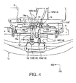
Figure 4 is a plan view of an electric vehicle wiring structure according to an embodiment of the present invention. - Selected embodiments will now be explained with reference to the drawings. It will be apparent to those skilled in the art from this disclosure that the following descriptions of the embodiments are provided for illustration only and not for the purpose of limiting the invention as defined by the appended claims and their equivalents.
- Referring initially to
Figure 1 , an electric vehicle structure of anelectric vehicle 1 is illustrated in accordance with a first embodiment. While the electric vehicle structure is illustrated as the front end of theelectric vehicle 1, the electric vehicle structure can be a rear end of an electric vehicle as needed and/or desired. In drawings, an arrow FR indicates a frontward direction of thevehicle 1, an arrow UP indicates an upward direction of thevehicle 1, and an arrow WD indicates a widthwise direction of thevehicle 1. - As shown in
Figures 1 and2 , in this embodiment, the electric vehicle structure includes afront vehicle compartment 2 that is formed in a frontward portion of thevehicle 1. Thefront vehicle compartment 2 is generally a space surrounded by adash panel 3 on a reward side, a pair of fender panels (not shown) on the widthwise sides, and abumper 4a and agrill 4b on a frontward side. An upper opening of thefront vehicle compartment 2 is covered with ahood panel 4c such that it can be opened and closed. Thefront vehicle compartment 2 houses apower unit 5, aninverter 6, acircuit box 7, and various other parts of thevehicle 1. Thepower unit 5 includes an integrated motor and reduction gear for driving thevehicle 1. Thecircuit box 7 constitutes one example of an "electrical component" mentioned therein. Thecircuit box 7 houses a DC/DC converter, fuses, a voltage meter, relays, etc. - As shown in
Figure 2 , afront side panel 8 is provided on each of both widthwise sides of thefront vehicle compartment 2. Thefront side panels 8 are arranged to be substantially aligned with a longitudinal direction (front to rear direction) of thevehicle 1. A hoodledge member 9 is provided on each side in a position slightly higher than the corresponding one of thefront side members 8. Thehood ledge members 9 are arranged to be substantially aligned with a longitudinal direction of thevehicle 1.Cross members front side members 8 substantially along a widthwise direction of thevehicle 1. Thecross members vehicle 1.Sub members cross members sub members cross members inverter 6, thecircuit box 7, and a PTC heater (not shown). In this embodiment, thefront side members 8, the hood ledgemembers 9, thecross members sub members vehicle 1. - As shown in
Figures 1 and4 , in this embodiment, thevehicle 1 is provided with a pair ofcharging ports 13 that serve as connectors for connecting an electrical plug (not shown) of an electric power supply line. Thecharging ports 13 are provided on a front end portion of thevehicle 1. Thecharging ports 13 are generically referred to singreference number 13 when describing common features. However, thecharging ports 13 are referred to afirst charging port 13A and a second (additional)charging port 13B when describing differences between thecharging ports - A frontward portion of each of the
charging ports 13 is covered with a movable lid formed on at least a portion of thegrill 4b. When a plug is to be connected for recharging, the movable lid can be opened so as to expose a frontward-facing portion of thecharging port 13. The plug is inserted through anopening 18 from the front and plugged into thecharging port 13. This arrangement is relatively conventional and will not be discussed and/or illustrated in detail. - An
electric charging harness 14 is connected to each of thecharging ports 13. Theelectric charging harnesses 14 serve to carry electric power transferred through thecharging port 13 from the electric power supply line to a battery (not shown) arranged rearward of thefront vehicle compartment 2. - In this embodiment, there are two
charging ports 13. Thecharging port 13A is configured and arranged for normal charging of the battery at a comparatively low voltage. Thecharging port 13B is configured and arranged for rapid charging of the battery at a comparatively high voltage. As seen inFigures 3 and4 , a singleelectric charging harness 14 is connected to thecharging port 13A, while two of theelectric charging harnesses 14 are connected to thecharging port 13B. The first connecting end of each of theelectric charging harness 14, which is opposite the end connected to therespective charging port 13, is connected to either thecircuit box 7, a junction box (not shown), a battery (not shown), or other electrical component arranged rearward of thecharging ports 13. - An
intermediate connector harnesses 14 connected to thecharging ports 13. Each of theharnesses 14 is divided into afrontward wiring portion 14F and arearward wiring portion 14R. Thefrontward wiring portion 14F is located on the chargingport 13 side of theintermediate connector rearward wiring portion 14R is located on the electrical component side of theintermediate connector frontward wiring portion 14F and therearward wiring portion 14R of each of the electric charging harnesses 14 are detachably connected together by the respectiveintermediate connector rearward wiring portions 14F and can be repeatedly connected and disconnected connection. Therefore, when maintenance or repairs are performed on one of the chargingports 13, a subassembly unit comprising the chargingport 13 and thefrontward wiring portion 14F of the electric chargingharness 14 can be removed by disconnecting theintermediate connector frontward wiring portion 14F from therearward wiring portion 14R. - In this embodiment, the
intermediate connectors front vehicle compartment 2. As a result, the lengths of thefrontward portions 14F of theharnesses 14 can be made shorter than if theintermediate connectors front vehicle compartment 2. Additionally, since each of the subassemblies includes only one of the chargingports 13 and only one or two of thefrontward wiring portions 14F, the subassemblies of the electric chargingharness 14 can be made to be a comparatively small and lightweight unit. - As shown in
Figures 1 to 4 , in this embodiment, thefrontward wiring portion 14F of each of theharnesses 14 is shorter than therearward wiring portion 14R. As a result, thefrontward portions 14F of theharnesses 14 can be made even shorter and the subassemblies each including only one of the chargingports 13 and only one or two of thefrontward wiring portions 14F can be made to be a comparatively small and lightweight unit. - Each of the
intermediate connectors female mating part male mating part male mating part female mating part female mating part intermediate connector rearward wiring portion 14R of the electric chargingharness 14 and themale mating part frontward wiring portion 14F. However, it is acceptable for the arrangement of the female and male mating parts to be reversed. - The mating part of each of the
intermediate connectors rearward wiring portion 14R of the electric charging harness 14 (e.g., thefemale mating part cross member 10F by abracket female portion male portion female mating part intermediate connectors female mating part male mating part - As shown in
Figure 4 , in this embodiment, theintermediate connectors inverter 6, which is a comparatively large electrical component arranged inside thefront vehicle compartment 2, in a horizontal direction in a plan view. This arrangement reduces the degree to which theinverter 6 becomes an obstruction and diminishes the efficiency with which the task of connecting and disconnecting thefemale mating parts male mating parts intermediate connectors inverter 6 in a forward direction, it is also acceptable for theintermediate connectors intermediate connectors inverter 6 as is done in this embodiment, the distance from the chargingports 13 to theintermediate connectors frontward portions 14F of theharnesses 14 can be shortened. As a result, each of the subassemblies includes the chargingport 13 and thefrontward wiring portion 14F of the electric chargingharness 14 can be made to be a comparatively small and lightweight unit. - In this embodiment, as shown in
Figure 1 , theintermediate connectors front vehicle compartment 2 such that a space S exists in a vertical direction directly above and/or directly below theintermediate connectors 15 and 16 (both directly above and directly below in this embodiment). As a result, the task of connecting and disconnecting thefemale mating parts male mating parts intermediate connectors - In this embodiment, the
intermediate connectors front end 12a of a radiatorcore support assembly 12 that is arranged in a frontward portion of thefront vehicle compartment 2 so as to span in a widthwise direction of thevehicle 1. The radiatorcore support assembly 12 includes a radiator core support and a condenser and other parts that are mounted to the radiator core support. The radiator core support is a frame like structure that functions as a portion of the vehicle body frame by spanning between frontward end portions of thefront side members 8. When thevehicle 1 undergoes a front collision, the radiator core support bears most of the load imparted from the front collision. Since theintermediate connectors front end 12a of the radiatorcore support assembly 12, theintermediate connectors front end 12a because the radiatorcore support assembly 12 bears the load coming from the front. - In this embodiment, since the
intermediate connectors frontward portions 14F of theharnesses 14, thefrontward wiring portion 14F of each of theharnesses 14 can be bent into a U-like shape or an S-like shape because the electric chargingharness 14 is pliable. Consequently, the load of a collision can be prevented from being imparted to one of theintermediate connectors harness 14 due to deformation of the electric chargingharness 14. As a result, theintermediate connectors - As explained previously, in this embodiment, the
intermediate connector harness 14 serving to connect the chargingport 13 to an electrical component arranged rearward of the chargingport 13. Theintermediate connector frontward wiring portion 14F and therearward wiring portion 14R of the electric chargingharness 14 together. With this configuration, when it is necessary to replace the chargingport 13, only the portion of the electric chargingharness 14 located on the chargingport 13 side of theintermediate connector port 13 and the portion of the electric chargingharness 14 located on the chargingport 13 side of theintermediate connector 15 or 16 (i.e., thefrontward wiring portion 14F) is replaced). Thus, the time and effort required to replace the chargingport 13 can be reduced in comparison with a configuration in which the entireelectric charging harness 14 must be replace along with the chargingport 13. Also, since theintermediate connector port 13, theintermediate connector port 13 is damaged due to a vehicle collision or the like. As a result, the time and effort required to replace the chargingport 13 can be prevented from increasing due to theintermediate connector - In this embodiment, the
intermediate connectors front vehicle compartment 2. Since thefront vehicle compartment 2 is configured and arranged such that a space for inserting a hand or a tool (e.g., the aforementioned space S) can be readily secured, thefemale mating part male mating part intermediate connectors front vehicle compartment 2 is formed in a frontward portion of the vehicle, so long as the chargingports 13 are provided on a front end portion of thevehicle 1, the portion of the each of theharnesses 14 located between the chargingport 13 and theintermediate connector 15 or 16 (i.e.,frontward portions 14F) can be made even shorter and the portion spanning from theintermediate connector port 13 and thefrontward wiring portion 14F of the electric charging harness 14) can be made to be a comparatively small and lightweight unit. As a result, it is easier to remove and install the chargingport 13 and the portion of the electric chargingharness 14 located on the chargingport 13 side of theintermediate connector harness 14 because the portion of the electric chargingharness 14 replaced when the chargingport 13 is replaced is comparatively short. - In this embodiment, the length of the
frontward wiring portion 14F is shorter than the length of therearward wiring portion 14R. As a result, the chargingport 13 and the portion of the electric chargingharness 14 located on the chargingport 13 side of theintermediate connector 15 or 16 (i.e., the subassembly comprising the chargingport 13 and thefrontward wiring portion 14F of the electric charging harness 14) can be made to be smaller and lighter in weight than a case in which thefrontward wiring portion 14F is longer than therearward wiring portion 14R. As a result, it is easier to remove and install the chargingport 13 and the portion of the electric chargingharness 14 located on the chargingport 13 side of theintermediate connector harness 14 because the portion of the electric chargingharness 14 replaced when the chargingport 13 is replaced is comparatively short. - In this embodiment, the
intermediate connectors front end 12a of a radiatorcore support assembly 12 arranged in a frontward portion of thefront vehicle compartment 2 so as to span in a widthwise direction of the vehicle. As a result, when thevehicle 1 undergoes a collision, the radiatorcore support assembly 12 bears most of the load imparted to thevehicle 1 and theintermediate connectors intermediate connectors front end 12a. - In this embodiment, the
intermediate connectors inverter 6 becomes an obstruction and diminishes the efficiency with which the task of connecting and disconnecting thefemale mating parts male mating parts - According to a preferred embodiment, an electric vehicle structure comprising: a charging port configured to be provided on a front end of a vehicle, the charging port including a connector that is configured to be connected to an electrical plug of an electric power supply line; an electric charging harness including a first wiring portion electrically connected to the charging port and a second wiring portion configured to be connected to an electrical component of the vehicle; and an intermediate connector releasably connecting the first wiring portion of the electric charging harness to the second wiring portion of the electric charging harness with a repeatable connecting and disconnecting connection, the intermediate connector being arranged rearward of a front end of a radiator core support assembly spanning across in a widthwise direction of the vehicle.
- Preferably, the first wiring portion is a frontward wiring portion, which extends longitudinally frontward of the intermediate connector, and the second wiring portion is a rearward wiring portion, which extends longitudinally rearward of the intermediate connector; wherein, preferably, the intermediate connector is provided in a front compartment formed in a frontward portion of the vehicle.
- Advantageously, the first wiring portion of the electric charging harness has a length that is shorter than a length of the second wiring portion of the electric charging harness and, preferably, the intermediate connector is arranged to be offset in a horizontal direction from an inverter arranged inside the vehicle as viewed in a plan view.
- It is preferred to establish an additional charging port electrically connected to two additional intermediate connectors by two additional first wiring portions, respectively, and two additional second wiring portions being electrically connected to the two additional intermediate connectors, respectively.
- According to an advantageous embodiment, the intermediate connector includes a first mating part attached to the first wiring portion and a second mating part attached to the second wiring portion, with the second mating part having a bracket configured to be mounted to a cross member of the vehicle, and/or the intermediate connector is located in a front vehicle compartment with the front vehicle compartment having an unobstructed access space existing in a vertical direction at least one of directly below the intermediate connector to an area below the vehicle and directly above the intermediate connector until a hood panel of the vehicle, while, preferably, the intermediate connector is arranged rearward of the vehicle with respect to the charging port.
- Alternatively, the intermediate connector is provided in a front compartment formed in a frontward portion of the vehicle, and/or the first wiring portion of the electric charging harness has a length that is shorter than a length of the second wiring portion of the electric charging harness.
- According to another preferred embodiment, the intermediate connector is arranged to be offset in a horizontal direction from an inverter arranged inside the vehicle as viewed in a plan view, and/or an additional charging port electrically connected to two additional intermediate connectors by two additional first wiring portions, respectively, and two additional second wiring portions being electrically connected to the two additional intermediate connectors, respectively, is provided.
- Advantageously, the intermediate connector includes a first mating part attached to the first wiring portion and a second mating part attached to the second wiring portion, with the second mating part having a bracket configured to be mounted to a crossmember of the vehicle.
- Preferably, the intermediate connector is located in a front vehicle compartment with the front vehicle compartment having an unobstructed access space existing in a vertical direction at least one of directly below the intermediate connector to an area below the vehicle and directly above the intermediate connector until a hood panel of the vehicle.
- Alternatively, the intermediate connector is arranged rearward of the vehicle with respect to the charging port.
- In understanding the scope of the present invention, the term "comprising" and its derivatives, as used herein, are intended to be open ended terms that specify the presence of the stated features, elements, components, groups, integers, and/or steps, but do not exclude the presence of other unstated features, elements, components, groups, integers and/or steps. The foregoing also applies to words having similar meanings such as the terms, "including", "having" and their derivatives. Also, the terms "part," "section," "portion," "member" or "element" when used in the singular can have the dual meaning of a single part or a plurality of parts. Also as used herein to describe the above embodiment(s), the following directional terms "frontward", "rearward", "above", "downward", "vertical", "horizontal", "below" and "transverse" as well as any other similar directional terms refer to those directions of an electric vehicle having the electric vehicle structure. Accordingly, these terms, as utilized to describe the electric vehicle structure should be interpreted relative to an electric vehicle having the electric vehicle structure.
- While only selected embodiments have been chosen to illustrate the present invention, it will be apparent to those skilled in the art from this disclosure that various changes and modifications can be made herein without departing from the scope of the invention as defined in the appended claims. For example, the size, shape, location or orientation of the various components can be changed as needed and/or desired. In other words, although in the embodiment the charging ports are provided on a frontward end portion of the vehicle, the invention is not limited to such an arrangement. Regardless of the particular positions of the charging ports and the intermediate connectors, the same operational effects can be obtained as with the embodiment so long as a harness exists between a charging port and an intermediate connector and the charging port and the intermediate connector can be arranged to be separated (spaced apart) from each other. Thus, the foregoing descriptions of the embodiments according to the present invention are provided for illustration only, and not for the purpose of limiting the invention as defined by the appended claims and their equivalents.
Claims (15)
- A wiring structure for an electric vehicle configured to supply electric power from a charging port to an electrical component of the vehicle through an electric charging harness,
said electric harness including a first wiring portion electrically connected to the charging port and a second wiring portion electrically connected to an electrical component of the vehicle, comprising:an intermediate connector releasably connecting the first wiring portion of the electric harness to the second wiring portion of the electric harness with a repeatable connecting and disconnecting connection. - The wiring structure according to claim 1, wherein the first wiring portion being a frontward wiring portion which extends longitudinally frontward of the intermediate connector and the second wiring portion being a rearward wiring portion which extends longitudinally rearward of the intermediate connector.
- The wiring structure according to claim 1 or 2, wherein the intermediate connector is provided in a front compartment formed in a frontward portion of the vehicle.
- The wiring structure according to any one of claims 1 to 3, wherein the first wiring portion of the electric charging harness has a length that is shorter than a length of the second wiring portion of the electric charging harness.
- The wiring structure according to any one of claims 1 to 4, wherein the intermediate connector is arranged rearward of a front end of a radiator core support assembly spanning across in a widthwise direction of the vehicle.
- The wiring structure according to any one of claims 1 to 5, wherein the intermediate connector is arranged to be offset in a horizontal direction from an inverter arranged inside the vehicle as viewed in a plan view.
- The wiring structure according to any one of claims 1 to 6, further comprising an additional charging port electrically connected to two additional intermediate connectors by two additional first wiring portions, respectively, and two additional second wiring portions being electrically connected to the two additional intermediate connectors, respectively.
- The wiring structure according to any one of claims 1 to 7, wherein the intermediate connector includes a first mating part attached to the first wiring portion and a second mating part attached to the second wiring portion, with the second mating part having a bracket configured to be mounted to a cross member of the vehicle.
- The wiring structure according to any one of claims 1 to 8, wherein the intermediate connector is located in a front vehicle compartment with the front vehicle compartment having an unobstructed access space existing in a vertical direction at least one of directly below the intermediate connector to an area below the vehicle and directly above the intermediate connector until a hood panel of the vehicle.
- Electric vehicle comprising a wiring structure according to one of the preceding claims 1 to 9.
- Electric vehicle according to claim 10, wherein the charging port is provided on a portion of the vehicle, in particular a front end of the vehicle.
- Electric vehicle according to claims 10 or 11, wherein the electrical component is a battery.
- Electric vehicle according to one of the preceding claims 10 to 12, wherein a plurality of intermediate connectors is provided rearwardly of the charging port.
- Electric vehicle according to claim 13, wherein the intermediate connectors are arranged rearward of a front end of a radiator core support assembly arranged in a frontward portion of a front vehicle compartment.
- Electrical vehicle as claimed in one of the preceding claims 10 to 14, comprising a harness between a charging port and an intermediate connector, wherein the intermediate connector is arranged to be separable from a harness connection to the charging port.
Applications Claiming Priority (3)
| Application Number | Priority Date | Filing Date | Title |
|---|---|---|---|
| JP2009098779A JP5206563B2 (en) | 2009-04-15 | 2009-04-15 | Electric vehicle wiring structure |
| EP10764157A EP2419299A1 (en) | 2009-04-15 | 2010-04-13 | Electric vehicle structure |
| PCT/IB2010/000814 WO2010119327A1 (en) | 2009-04-15 | 2010-04-13 | Electric vehicle structure |
Related Parent Applications (1)
| Application Number | Title | Priority Date | Filing Date |
|---|---|---|---|
| EP10764157A Division EP2419299A1 (en) | 2009-04-15 | 2010-04-13 | Electric vehicle structure |
Publications (2)
| Publication Number | Publication Date |
|---|---|
| EP3006242A1 true EP3006242A1 (en) | 2016-04-13 |
| EP3006242B1 EP3006242B1 (en) | 2020-01-08 |
Family
ID=42982152
Family Applications (2)
| Application Number | Title | Priority Date | Filing Date |
|---|---|---|---|
| EP10764157A Withdrawn EP2419299A1 (en) | 2009-04-15 | 2010-04-13 | Electric vehicle structure |
| EP15001084.1A Active EP3006242B1 (en) | 2009-04-15 | 2010-04-13 | Electric vehicle structure |
Family Applications Before (1)
| Application Number | Title | Priority Date | Filing Date |
|---|---|---|---|
| EP10764157A Withdrawn EP2419299A1 (en) | 2009-04-15 | 2010-04-13 | Electric vehicle structure |
Country Status (5)
| Country | Link |
|---|---|
| US (1) | US8928279B2 (en) |
| EP (2) | EP2419299A1 (en) |
| JP (1) | JP5206563B2 (en) |
| CN (1) | CN102438862B (en) |
| WO (1) | WO2010119327A1 (en) |
Families Citing this family (23)
| Publication number | Priority date | Publication date | Assignee | Title |
|---|---|---|---|---|
| JP6012143B2 (en) | 2011-05-17 | 2016-10-25 | 日産自動車株式会社 | Electric vehicle charging / discharging harness wiring structure |
| JP5714720B2 (en) | 2011-11-14 | 2015-05-07 | 本田技研工業株式会社 | Electric car |
| WO2013073484A1 (en) * | 2011-11-14 | 2013-05-23 | 本田技研工業株式会社 | Charging opening structure for electric automobile |
| JP2013180728A (en) * | 2012-03-05 | 2013-09-12 | Nissan Motor Co Ltd | Harness wiring structure of electric vehicle |
| JP5835019B2 (en) * | 2012-03-05 | 2015-12-24 | 日産自動車株式会社 | Electric vehicle harness arrangement structure |
| JP2013180727A (en) * | 2012-03-05 | 2013-09-12 | Nissan Motor Co Ltd | Harness distribution structure of electric vehicle |
| KR101394030B1 (en) | 2012-06-05 | 2014-05-09 | 현대자동차 주식회사 | Charge device for vehicle |
| JP5884699B2 (en) * | 2012-09-28 | 2016-03-15 | 三菱自動車工業株式会社 | Charging connector housing device for truck electric vehicle |
| JP5970562B2 (en) * | 2012-12-25 | 2016-08-17 | 川崎重工業株式会社 | Electric vehicle |
| US9376025B2 (en) | 2013-02-06 | 2016-06-28 | Lg Electronics Inc. | Charging apparatus and electric vehicle including the same |
| JP6210092B2 (en) * | 2015-07-14 | 2017-10-11 | トヨタ自動車株式会社 | Automobile |
| US20170259678A1 (en) * | 2016-03-08 | 2017-09-14 | Faraday&Future Inc. | Electric vehicle charge port |
| JP6982799B2 (en) * | 2017-12-28 | 2021-12-17 | スズキ株式会社 | Power supply for electric vehicles |
| JP7063189B2 (en) * | 2018-08-21 | 2022-05-09 | トヨタ自動車株式会社 | Vehicle structure of electric vehicle |
| JP7056468B2 (en) | 2018-08-24 | 2022-04-19 | トヨタ自動車株式会社 | Vehicle underfloor structure |
| JP7091936B2 (en) * | 2018-08-24 | 2022-06-28 | トヨタ自動車株式会社 | Vehicle underfloor structure |
| JP7052673B2 (en) * | 2018-10-29 | 2022-04-12 | トヨタ自動車株式会社 | Electric vehicle |
| CN109552094B (en) * | 2019-01-16 | 2024-09-13 | 中国第一汽车股份有限公司 | A charging port and high-voltage wire harness arrangement structure |
| JP7172746B2 (en) | 2019-03-06 | 2022-11-16 | トヨタ自動車株式会社 | Power unit mounting structure |
| TWI899183B (en) * | 2020-03-16 | 2025-10-01 | 美商特斯拉公司 | High power shielded busbar for electric vehicle charging and power distribution |
| CN115461238B (en) * | 2020-04-27 | 2025-11-25 | 日产自动车株式会社 | Protector structure for electrical components |
| JP7796569B2 (en) * | 2022-03-24 | 2026-01-09 | 日産自動車株式会社 | Wire mounting structure |
| JP2025113896A (en) * | 2024-01-23 | 2025-08-04 | トヨタ自動車株式会社 | electric car |
Citations (5)
| Publication number | Priority date | Publication date | Assignee | Title |
|---|---|---|---|---|
| US5565755A (en) * | 1993-04-19 | 1996-10-15 | Keith; Arlie L. | Charging batteries of electric vehicles |
| US5885098A (en) * | 1997-09-12 | 1999-03-23 | Phillips & Temro Industries Inc. | Cord set receptacle |
| JPH11332003A (en) | 1998-05-12 | 1999-11-30 | Kansei Corp | Electric vehicle charging section structure |
| JP2000253511A (en) * | 1999-03-04 | 2000-09-14 | Yazaki Corp | Connection construction for power unit for ev |
| JP2008211943A (en) * | 2007-02-28 | 2008-09-11 | Toyota Motor Corp | Connection mechanism and vehicle equipped with the connection mechanism |
Family Cites Families (14)
| Publication number | Priority date | Publication date | Assignee | Title |
|---|---|---|---|---|
| US5202617A (en) * | 1991-10-15 | 1993-04-13 | Norvik Technologies Inc. | Charging station for electric vehicles |
| US5548200A (en) * | 1994-07-06 | 1996-08-20 | Norvik Traction Inc. | Universal charging station and method for charging electric vehicle batteries |
| JPH0998518A (en) * | 1995-10-03 | 1997-04-08 | Mitsubishi Motors Corp | Battery connection device for electric vehicle, control device for electric vehicle |
| JP3228097B2 (en) * | 1995-10-19 | 2001-11-12 | 株式会社日立製作所 | Charging system and electric vehicle |
| JP4736455B2 (en) * | 2005-02-10 | 2011-07-27 | 日産自動車株式会社 | Motor room component mounting structure and motor room shock absorption structure |
| JP4818628B2 (en) * | 2005-03-29 | 2011-11-16 | ダイハツ工業株式会社 | Transmission |
| ITMI20051055A1 (en) * | 2005-06-07 | 2006-12-08 | Ct De Recherches En Machines Thermiques | "ELECTRIC PROPULSION VEHICLE WITH GAS GENERATOR FOR BATTERY RECHARGING AND FOR DIRECT POWER SUPPLY TO MOTORS." |
| JP4670656B2 (en) * | 2006-01-24 | 2011-04-13 | 株式会社デンソー | Vehicle power supply device |
| JP4906164B2 (en) * | 2007-07-19 | 2012-03-28 | アイシン・エィ・ダブリュ株式会社 | Map display device, map display method, and computer program |
| JP4935567B2 (en) * | 2007-08-02 | 2012-05-23 | トヨタ自動車株式会社 | housing |
| JP5291909B2 (en) * | 2007-09-21 | 2013-09-18 | 富士重工業株式会社 | Electric vehicle charging device |
| JP4450066B2 (en) * | 2007-12-25 | 2010-04-14 | 日産自動車株式会社 | Vehicle front structure |
| JP5259220B2 (en) * | 2008-03-25 | 2013-08-07 | 富士重工業株式会社 | Electric car |
| JP5018830B2 (en) * | 2009-06-11 | 2012-09-05 | 日産自動車株式会社 | Charging port lid opening / closing structure |
-
2009
- 2009-04-15 JP JP2009098779A patent/JP5206563B2/en active Active
-
2010
- 2010-04-13 US US13/263,918 patent/US8928279B2/en active Active
- 2010-04-13 CN CN201080015733.2A patent/CN102438862B/en active Active
- 2010-04-13 EP EP10764157A patent/EP2419299A1/en not_active Withdrawn
- 2010-04-13 EP EP15001084.1A patent/EP3006242B1/en active Active
- 2010-04-13 WO PCT/IB2010/000814 patent/WO2010119327A1/en not_active Ceased
Patent Citations (5)
| Publication number | Priority date | Publication date | Assignee | Title |
|---|---|---|---|---|
| US5565755A (en) * | 1993-04-19 | 1996-10-15 | Keith; Arlie L. | Charging batteries of electric vehicles |
| US5885098A (en) * | 1997-09-12 | 1999-03-23 | Phillips & Temro Industries Inc. | Cord set receptacle |
| JPH11332003A (en) | 1998-05-12 | 1999-11-30 | Kansei Corp | Electric vehicle charging section structure |
| JP2000253511A (en) * | 1999-03-04 | 2000-09-14 | Yazaki Corp | Connection construction for power unit for ev |
| JP2008211943A (en) * | 2007-02-28 | 2008-09-11 | Toyota Motor Corp | Connection mechanism and vehicle equipped with the connection mechanism |
Also Published As
| Publication number | Publication date |
|---|---|
| EP2419299A1 (en) | 2012-02-22 |
| US8928279B2 (en) | 2015-01-06 |
| JP5206563B2 (en) | 2013-06-12 |
| US20120038319A1 (en) | 2012-02-16 |
| EP3006242B1 (en) | 2020-01-08 |
| JP2010247642A (en) | 2010-11-04 |
| CN102438862B (en) | 2014-05-07 |
| CN102438862A (en) | 2012-05-02 |
| WO2010119327A1 (en) | 2010-10-21 |
Similar Documents
| Publication | Publication Date | Title |
|---|---|---|
| EP3006242B1 (en) | Electric vehicle structure | |
| US8820452B2 (en) | Vehicle component mounting arrangement | |
| JP5776852B2 (en) | High-voltage harness connection structure for electric vehicles | |
| JP5211081B2 (en) | Electric parts mounting structure for electric vehicles | |
| JP5690055B2 (en) | Electric vehicle component mounting structure | |
| JP6706507B2 (en) | vehicle | |
| US10608385B2 (en) | Connector structure and electric vehicle | |
| DE112007001145B4 (en) | storage device | |
| EP3552854B1 (en) | Arrangement structure of electrical apparatus in electric automobile | |
| JP7151113B2 (en) | Electric vehicle front unit mounting structure | |
| JP6688851B2 (en) | vehicle | |
| JP7151114B2 (en) | Electric vehicle front unit mounting structure | |
| JP7087834B2 (en) | In-vehicle structure of electrical equipment | |
| JP7155561B2 (en) | Electric vehicle front unit mounting structure | |
| JP7345730B2 (en) | Harness arrangement structure | |
| JP7309314B2 (en) | vehicle battery pack | |
| WO2020137471A1 (en) | Power supply device and vehicle | |
| JP2016068605A (en) | Connecting structure of vehicle optional component | |
| WO2020137472A1 (en) | Wire harness assembly and wire harness assembly mounting structure | |
| JP2026000597A (en) | Vehicle cable routing structure | |
| JP2019021639A (en) | Connector structure and electric vehicle |
Legal Events
| Date | Code | Title | Description |
|---|---|---|---|
| PUAI | Public reference made under article 153(3) epc to a published international application that has entered the european phase |
Free format text: ORIGINAL CODE: 0009012 |
|
| 17P | Request for examination filed |
Effective date: 20150415 |
|
| AC | Divisional application: reference to earlier application |
Ref document number: 2419299 Country of ref document: EP Kind code of ref document: P |
|
| AK | Designated contracting states |
Kind code of ref document: A1 Designated state(s): AT BE BG CH CY CZ DE DK EE ES FI FR GB GR HR HU IE IS IT LI LT LU LV MC MK MT NL NO PL PT RO SE SI SK SM TR |
|
| STAA | Information on the status of an ep patent application or granted ep patent |
Free format text: STATUS: EXAMINATION IS IN PROGRESS |
|
| 17Q | First examination report despatched |
Effective date: 20180117 |
|
| REG | Reference to a national code |
Ref country code: DE Ref legal event code: R079 Ref document number: 602010062762 Country of ref document: DE Free format text: PREVIOUS MAIN CLASS: B60K0001000000 Ipc: B60L0050510000 |
|
| RIC1 | Information provided on ipc code assigned before grant |
Ipc: B60L 58/20 20190101ALI20190221BHEP Ipc: B60L 50/51 20190101AFI20190221BHEP Ipc: B60L 53/10 20190101ALI20190221BHEP Ipc: B60L 53/16 20190101ALI20190221BHEP |
|
| GRAP | Despatch of communication of intention to grant a patent |
Free format text: ORIGINAL CODE: EPIDOSNIGR1 |
|
| STAA | Information on the status of an ep patent application or granted ep patent |
Free format text: STATUS: GRANT OF PATENT IS INTENDED |
|
| INTG | Intention to grant announced |
Effective date: 20190412 |
|
| GRAJ | Information related to disapproval of communication of intention to grant by the applicant or resumption of examination proceedings by the epo deleted |
Free format text: ORIGINAL CODE: EPIDOSDIGR1 |
|
| STAA | Information on the status of an ep patent application or granted ep patent |
Free format text: STATUS: EXAMINATION IS IN PROGRESS |
|
| INTC | Intention to grant announced (deleted) | ||
| GRAP | Despatch of communication of intention to grant a patent |
Free format text: ORIGINAL CODE: EPIDOSNIGR1 |
|
| STAA | Information on the status of an ep patent application or granted ep patent |
Free format text: STATUS: GRANT OF PATENT IS INTENDED |
|
| INTG | Intention to grant announced |
Effective date: 20190918 |
|
| GRAS | Grant fee paid |
Free format text: ORIGINAL CODE: EPIDOSNIGR3 |
|
| GRAA | (expected) grant |
Free format text: ORIGINAL CODE: 0009210 |
|
| STAA | Information on the status of an ep patent application or granted ep patent |
Free format text: STATUS: THE PATENT HAS BEEN GRANTED |
|
| AC | Divisional application: reference to earlier application |
Ref document number: 2419299 Country of ref document: EP Kind code of ref document: P |
|
| AK | Designated contracting states |
Kind code of ref document: B1 Designated state(s): AT BE BG CH CY CZ DE DK EE ES FI FR GB GR HR HU IE IS IT LI LT LU LV MC MK MT NL NO PL PT RO SE SI SK SM TR |
|
| REG | Reference to a national code |
Ref country code: GB Ref legal event code: FG4D |
|
| REG | Reference to a national code |
Ref country code: CH Ref legal event code: EP |
|
| REG | Reference to a national code |
Ref country code: IE Ref legal event code: FG4D |
|
| REG | Reference to a national code |
Ref country code: DE Ref legal event code: R096 Ref document number: 602010062762 Country of ref document: DE |
|
| REG | Reference to a national code |
Ref country code: AT Ref legal event code: REF Ref document number: 1222271 Country of ref document: AT Kind code of ref document: T Effective date: 20200215 |
|
| REG | Reference to a national code |
Ref country code: NL Ref legal event code: MP Effective date: 20200108 |
|
| REG | Reference to a national code |
Ref country code: LT Ref legal event code: MG4D |
|
| PG25 | Lapsed in a contracting state [announced via postgrant information from national office to epo] |
Ref country code: LT Free format text: LAPSE BECAUSE OF FAILURE TO SUBMIT A TRANSLATION OF THE DESCRIPTION OR TO PAY THE FEE WITHIN THE PRESCRIBED TIME-LIMIT Effective date: 20200108 Ref country code: NL Free format text: LAPSE BECAUSE OF FAILURE TO SUBMIT A TRANSLATION OF THE DESCRIPTION OR TO PAY THE FEE WITHIN THE PRESCRIBED TIME-LIMIT Effective date: 20200108 Ref country code: NO Free format text: LAPSE BECAUSE OF FAILURE TO SUBMIT A TRANSLATION OF THE DESCRIPTION OR TO PAY THE FEE WITHIN THE PRESCRIBED TIME-LIMIT Effective date: 20200408 Ref country code: PT Free format text: LAPSE BECAUSE OF FAILURE TO SUBMIT A TRANSLATION OF THE DESCRIPTION OR TO PAY THE FEE WITHIN THE PRESCRIBED TIME-LIMIT Effective date: 20200531 Ref country code: FI Free format text: LAPSE BECAUSE OF FAILURE TO SUBMIT A TRANSLATION OF THE DESCRIPTION OR TO PAY THE FEE WITHIN THE PRESCRIBED TIME-LIMIT Effective date: 20200108 |
|
| PG25 | Lapsed in a contracting state [announced via postgrant information from national office to epo] |
Ref country code: IS Free format text: LAPSE BECAUSE OF FAILURE TO SUBMIT A TRANSLATION OF THE DESCRIPTION OR TO PAY THE FEE WITHIN THE PRESCRIBED TIME-LIMIT Effective date: 20200508 Ref country code: GR Free format text: LAPSE BECAUSE OF FAILURE TO SUBMIT A TRANSLATION OF THE DESCRIPTION OR TO PAY THE FEE WITHIN THE PRESCRIBED TIME-LIMIT Effective date: 20200409 Ref country code: SE Free format text: LAPSE BECAUSE OF FAILURE TO SUBMIT A TRANSLATION OF THE DESCRIPTION OR TO PAY THE FEE WITHIN THE PRESCRIBED TIME-LIMIT Effective date: 20200108 Ref country code: LV Free format text: LAPSE BECAUSE OF FAILURE TO SUBMIT A TRANSLATION OF THE DESCRIPTION OR TO PAY THE FEE WITHIN THE PRESCRIBED TIME-LIMIT Effective date: 20200108 Ref country code: HR Free format text: LAPSE BECAUSE OF FAILURE TO SUBMIT A TRANSLATION OF THE DESCRIPTION OR TO PAY THE FEE WITHIN THE PRESCRIBED TIME-LIMIT Effective date: 20200108 Ref country code: BG Free format text: LAPSE BECAUSE OF FAILURE TO SUBMIT A TRANSLATION OF THE DESCRIPTION OR TO PAY THE FEE WITHIN THE PRESCRIBED TIME-LIMIT Effective date: 20200408 |
|
| REG | Reference to a national code |
Ref country code: DE Ref legal event code: R097 Ref document number: 602010062762 Country of ref document: DE |
|
| PG25 | Lapsed in a contracting state [announced via postgrant information from national office to epo] |
Ref country code: ES Free format text: LAPSE BECAUSE OF FAILURE TO SUBMIT A TRANSLATION OF THE DESCRIPTION OR TO PAY THE FEE WITHIN THE PRESCRIBED TIME-LIMIT Effective date: 20200108 Ref country code: DK Free format text: LAPSE BECAUSE OF FAILURE TO SUBMIT A TRANSLATION OF THE DESCRIPTION OR TO PAY THE FEE WITHIN THE PRESCRIBED TIME-LIMIT Effective date: 20200108 Ref country code: SM Free format text: LAPSE BECAUSE OF FAILURE TO SUBMIT A TRANSLATION OF THE DESCRIPTION OR TO PAY THE FEE WITHIN THE PRESCRIBED TIME-LIMIT Effective date: 20200108 Ref country code: EE Free format text: LAPSE BECAUSE OF FAILURE TO SUBMIT A TRANSLATION OF THE DESCRIPTION OR TO PAY THE FEE WITHIN THE PRESCRIBED TIME-LIMIT Effective date: 20200108 Ref country code: CZ Free format text: LAPSE BECAUSE OF FAILURE TO SUBMIT A TRANSLATION OF THE DESCRIPTION OR TO PAY THE FEE WITHIN THE PRESCRIBED TIME-LIMIT Effective date: 20200108 Ref country code: RO Free format text: LAPSE BECAUSE OF FAILURE TO SUBMIT A TRANSLATION OF THE DESCRIPTION OR TO PAY THE FEE WITHIN THE PRESCRIBED TIME-LIMIT Effective date: 20200108 Ref country code: SK Free format text: LAPSE BECAUSE OF FAILURE TO SUBMIT A TRANSLATION OF THE DESCRIPTION OR TO PAY THE FEE WITHIN THE PRESCRIBED TIME-LIMIT Effective date: 20200108 |
|
| PLBE | No opposition filed within time limit |
Free format text: ORIGINAL CODE: 0009261 |
|
| STAA | Information on the status of an ep patent application or granted ep patent |
Free format text: STATUS: NO OPPOSITION FILED WITHIN TIME LIMIT |
|
| REG | Reference to a national code |
Ref country code: AT Ref legal event code: MK05 Ref document number: 1222271 Country of ref document: AT Kind code of ref document: T Effective date: 20200108 |
|
| PG25 | Lapsed in a contracting state [announced via postgrant information from national office to epo] |
Ref country code: MC Free format text: LAPSE BECAUSE OF FAILURE TO SUBMIT A TRANSLATION OF THE DESCRIPTION OR TO PAY THE FEE WITHIN THE PRESCRIBED TIME-LIMIT Effective date: 20200108 |
|
| REG | Reference to a national code |
Ref country code: CH Ref legal event code: PL |
|
| 26N | No opposition filed |
Effective date: 20201009 |
|
| PG25 | Lapsed in a contracting state [announced via postgrant information from national office to epo] |
Ref country code: IT Free format text: LAPSE BECAUSE OF FAILURE TO SUBMIT A TRANSLATION OF THE DESCRIPTION OR TO PAY THE FEE WITHIN THE PRESCRIBED TIME-LIMIT Effective date: 20200108 Ref country code: LU Free format text: LAPSE BECAUSE OF NON-PAYMENT OF DUE FEES Effective date: 20200413 Ref country code: CH Free format text: LAPSE BECAUSE OF NON-PAYMENT OF DUE FEES Effective date: 20200430 Ref country code: AT Free format text: LAPSE BECAUSE OF FAILURE TO SUBMIT A TRANSLATION OF THE DESCRIPTION OR TO PAY THE FEE WITHIN THE PRESCRIBED TIME-LIMIT Effective date: 20200108 Ref country code: LI Free format text: LAPSE BECAUSE OF NON-PAYMENT OF DUE FEES Effective date: 20200430 |
|
| REG | Reference to a national code |
Ref country code: BE Ref legal event code: MM Effective date: 20200430 |
|
| PG25 | Lapsed in a contracting state [announced via postgrant information from national office to epo] |
Ref country code: BE Free format text: LAPSE BECAUSE OF NON-PAYMENT OF DUE FEES Effective date: 20200430 Ref country code: PL Free format text: LAPSE BECAUSE OF FAILURE TO SUBMIT A TRANSLATION OF THE DESCRIPTION OR TO PAY THE FEE WITHIN THE PRESCRIBED TIME-LIMIT Effective date: 20200108 Ref country code: SI Free format text: LAPSE BECAUSE OF FAILURE TO SUBMIT A TRANSLATION OF THE DESCRIPTION OR TO PAY THE FEE WITHIN THE PRESCRIBED TIME-LIMIT Effective date: 20200108 |
|
| PG25 | Lapsed in a contracting state [announced via postgrant information from national office to epo] |
Ref country code: IE Free format text: LAPSE BECAUSE OF NON-PAYMENT OF DUE FEES Effective date: 20200413 |
|
| PG25 | Lapsed in a contracting state [announced via postgrant information from national office to epo] |
Ref country code: TR Free format text: LAPSE BECAUSE OF FAILURE TO SUBMIT A TRANSLATION OF THE DESCRIPTION OR TO PAY THE FEE WITHIN THE PRESCRIBED TIME-LIMIT Effective date: 20200108 Ref country code: MT Free format text: LAPSE BECAUSE OF FAILURE TO SUBMIT A TRANSLATION OF THE DESCRIPTION OR TO PAY THE FEE WITHIN THE PRESCRIBED TIME-LIMIT Effective date: 20200108 Ref country code: CY Free format text: LAPSE BECAUSE OF FAILURE TO SUBMIT A TRANSLATION OF THE DESCRIPTION OR TO PAY THE FEE WITHIN THE PRESCRIBED TIME-LIMIT Effective date: 20200108 |
|
| PG25 | Lapsed in a contracting state [announced via postgrant information from national office to epo] |
Ref country code: MK Free format text: LAPSE BECAUSE OF FAILURE TO SUBMIT A TRANSLATION OF THE DESCRIPTION OR TO PAY THE FEE WITHIN THE PRESCRIBED TIME-LIMIT Effective date: 20200108 |
|
| PGFP | Annual fee paid to national office [announced via postgrant information from national office to epo] |
Ref country code: DE Payment date: 20250319 Year of fee payment: 16 |
|
| PGFP | Annual fee paid to national office [announced via postgrant information from national office to epo] |
Ref country code: GB Payment date: 20260319 Year of fee payment: 17 |
|
| PGFP | Annual fee paid to national office [announced via postgrant information from national office to epo] |
Ref country code: FR Payment date: 20260320 Year of fee payment: 17 |