EP3005246B1 - Modulares rfid-system mit passiven rfid-modul und activen rfid-modul - Google Patents
Modulares rfid-system mit passiven rfid-modul und activen rfid-modul Download PDFInfo
- Publication number
- EP3005246B1 EP3005246B1 EP14731752.3A EP14731752A EP3005246B1 EP 3005246 B1 EP3005246 B1 EP 3005246B1 EP 14731752 A EP14731752 A EP 14731752A EP 3005246 B1 EP3005246 B1 EP 3005246B1
- Authority
- EP
- European Patent Office
- Prior art keywords
- module
- support
- phase
- memory
- controller
- Prior art date
- Legal status (The legal status is an assumption and is not a legal conclusion. Google has not performed a legal analysis and makes no representation as to the accuracy of the status listed.)
- Active
Links
Images

Classifications
-
- G—PHYSICS
- G06—COMPUTING; CALCULATING OR COUNTING
- G06K—GRAPHICAL DATA READING; PRESENTATION OF DATA; RECORD CARRIERS; HANDLING RECORD CARRIERS
- G06K19/00—Record carriers for use with machines and with at least a part designed to carry digital markings
- G06K19/06—Record carriers for use with machines and with at least a part designed to carry digital markings characterised by the kind of the digital marking, e.g. shape, nature, code
- G06K19/067—Record carriers with conductive marks, printed circuits or semiconductor circuit elements, e.g. credit or identity cards also with resonating or responding marks without active components
- G06K19/07—Record carriers with conductive marks, printed circuits or semiconductor circuit elements, e.g. credit or identity cards also with resonating or responding marks without active components with integrated circuit chips
- G06K19/0723—Record carriers with conductive marks, printed circuits or semiconductor circuit elements, e.g. credit or identity cards also with resonating or responding marks without active components with integrated circuit chips the record carrier comprising an arrangement for non-contact communication, e.g. wireless communication circuits on transponder cards, non-contact smart cards or RFIDs
-
- G—PHYSICS
- G06—COMPUTING; CALCULATING OR COUNTING
- G06K—GRAPHICAL DATA READING; PRESENTATION OF DATA; RECORD CARRIERS; HANDLING RECORD CARRIERS
- G06K19/00—Record carriers for use with machines and with at least a part designed to carry digital markings
- G06K19/06—Record carriers for use with machines and with at least a part designed to carry digital markings characterised by the kind of the digital marking, e.g. shape, nature, code
- G06K19/067—Record carriers with conductive marks, printed circuits or semiconductor circuit elements, e.g. credit or identity cards also with resonating or responding marks without active components
- G06K19/07—Record carriers with conductive marks, printed circuits or semiconductor circuit elements, e.g. credit or identity cards also with resonating or responding marks without active components with integrated circuit chips
- G06K19/077—Constructional details, e.g. mounting of circuits in the carrier
- G06K19/07737—Constructional details, e.g. mounting of circuits in the carrier the record carrier consisting of two or more mechanically separable parts
-
- G—PHYSICS
- G06—COMPUTING; CALCULATING OR COUNTING
- G06F—ELECTRIC DIGITAL DATA PROCESSING
- G06F16/00—Information retrieval; Database structures therefor; File system structures therefor
- G06F16/20—Information retrieval; Database structures therefor; File system structures therefor of structured data, e.g. relational data
- G06F16/24—Querying
- G06F16/245—Query processing
- G06F16/24569—Query processing with adaptation to specific hardware, e.g. adapted for using GPUs or SSDs
-
- G—PHYSICS
- G06—COMPUTING; CALCULATING OR COUNTING
- G06K—GRAPHICAL DATA READING; PRESENTATION OF DATA; RECORD CARRIERS; HANDLING RECORD CARRIERS
- G06K19/00—Record carriers for use with machines and with at least a part designed to carry digital markings
- G06K19/06—Record carriers for use with machines and with at least a part designed to carry digital markings characterised by the kind of the digital marking, e.g. shape, nature, code
- G06K19/067—Record carriers with conductive marks, printed circuits or semiconductor circuit elements, e.g. credit or identity cards also with resonating or responding marks without active components
- G06K19/07—Record carriers with conductive marks, printed circuits or semiconductor circuit elements, e.g. credit or identity cards also with resonating or responding marks without active components with integrated circuit chips
- G06K19/0701—Record carriers with conductive marks, printed circuits or semiconductor circuit elements, e.g. credit or identity cards also with resonating or responding marks without active components with integrated circuit chips at least one of the integrated circuit chips comprising an arrangement for power management
- G06K19/0702—Record carriers with conductive marks, printed circuits or semiconductor circuit elements, e.g. credit or identity cards also with resonating or responding marks without active components with integrated circuit chips at least one of the integrated circuit chips comprising an arrangement for power management the arrangement including a battery
-
- G—PHYSICS
- G06—COMPUTING; CALCULATING OR COUNTING
- G06K—GRAPHICAL DATA READING; PRESENTATION OF DATA; RECORD CARRIERS; HANDLING RECORD CARRIERS
- G06K19/00—Record carriers for use with machines and with at least a part designed to carry digital markings
- G06K19/06—Record carriers for use with machines and with at least a part designed to carry digital markings characterised by the kind of the digital marking, e.g. shape, nature, code
- G06K19/067—Record carriers with conductive marks, printed circuits or semiconductor circuit elements, e.g. credit or identity cards also with resonating or responding marks without active components
- G06K19/07—Record carriers with conductive marks, printed circuits or semiconductor circuit elements, e.g. credit or identity cards also with resonating or responding marks without active components with integrated circuit chips
- G06K19/077—Constructional details, e.g. mounting of circuits in the carrier
- G06K19/0772—Physical layout of the record carrier
-
- G—PHYSICS
- G06—COMPUTING; CALCULATING OR COUNTING
- G06K—GRAPHICAL DATA READING; PRESENTATION OF DATA; RECORD CARRIERS; HANDLING RECORD CARRIERS
- G06K19/00—Record carriers for use with machines and with at least a part designed to carry digital markings
- G06K19/06—Record carriers for use with machines and with at least a part designed to carry digital markings characterised by the kind of the digital marking, e.g. shape, nature, code
- G06K19/067—Record carriers with conductive marks, printed circuits or semiconductor circuit elements, e.g. credit or identity cards also with resonating or responding marks without active components
- G06K19/07—Record carriers with conductive marks, printed circuits or semiconductor circuit elements, e.g. credit or identity cards also with resonating or responding marks without active components with integrated circuit chips
- G06K19/077—Constructional details, e.g. mounting of circuits in the carrier
- G06K19/07749—Constructional details, e.g. mounting of circuits in the carrier the record carrier being capable of non-contact communication, e.g. constructional details of the antenna of a non-contact smart card
-
- G—PHYSICS
- G06—COMPUTING; CALCULATING OR COUNTING
- G06K—GRAPHICAL DATA READING; PRESENTATION OF DATA; RECORD CARRIERS; HANDLING RECORD CARRIERS
- G06K7/00—Methods or arrangements for sensing record carriers, e.g. for reading patterns
- G06K7/10—Methods or arrangements for sensing record carriers, e.g. for reading patterns by electromagnetic radiation, e.g. optical sensing; by corpuscular radiation
- G06K7/10009—Methods or arrangements for sensing record carriers, e.g. for reading patterns by electromagnetic radiation, e.g. optical sensing; by corpuscular radiation sensing by radiation using wavelengths larger than 0.1 mm, e.g. radio-waves or microwaves
- G06K7/10297—Methods or arrangements for sensing record carriers, e.g. for reading patterns by electromagnetic radiation, e.g. optical sensing; by corpuscular radiation sensing by radiation using wavelengths larger than 0.1 mm, e.g. radio-waves or microwaves arrangements for handling protocols designed for non-contact record carriers such as RFIDs NFCs, e.g. ISO/IEC 14443 and 18092
Definitions
- the present invention relates to a modular radio-identification system, and to a method of assembling such a modular radio-identification system.
- the invention is in the field of identifying, locating, supervising and monitoring objects or people remotely, using RFID radio identification technologies for "Radio Frequency Identification”.
- the passive RFID module In RFID technology, three modules (otherwise called marker, tag or transponder) of radio-identification are known, namely the passive RFID module, the active RFID module and the semi-passive RFID module.
- the passive RFID module simply integrates a memory, of the electronic chip type, and an antenna connected to the memory to enable short-range reading of identification data stored in the memory by a reader; the reader being constituted by a radiofrequency transmitter which activates the passive RFID module by supplying it at a short distance the energy it needs to communicate its identification data.
- the passive RFID module thus allows the communication of the identification data to and at the initiative of an external infrastructure, by means of a short-range reader, typically up to ten meters.
- the active RFID module integrates a controller provided with a memory and connected to a battery pack and also to a radiofrequency transmitter / receiver.
- An active RFID module allows identification, supervision and possibly recording of measurement data from one or more sensors on the module. This active RFID module thus enables the communication of data (identification data stored in the memory and possibly measurement data from the sensor or sensors) to an external infrastructure and at the initiative of the controller of the module that sends the data. at a regular time interval, with a long range, typically a hundred meters.
- the semi-passive RFID module also known as "BAP tag” for “Battery-Assisted Passive tag” or battery-powered passive marker, combines active RFID technology and passive RFID technology, integrating a memory connected to an antenna and a battery.
- the battery makes it possible to increase the reading range of the identification data stored in the memory by a medium-range reader, typically up to a few tens of meters; the communication between the semi-passive RFID module and the external infrastructure is at the initiative of the infrastructure as in passive technology, and not at the initiative of the module, over a long range, typically a hundred meter.
- the three aforementioned modules are all fixed in their respective technologies, so that it is necessary to use two separate modules, namely an active RFID module and a passive or semi-passive RFID module, to realize, on one side, identification alone over a long period and, on the other hand, identification, supervision and registration over a short period.
- the only passive or semi-passive RFID technology is not suitable for supervision phases because it does not meet the need for supervision and recording of data measured by sensors; no supervision is possible with passive and semi-passive RFID modules due to the infrastructure communication initiative.
- the only active RFID technology is not adapted for the storage phases because the management of the batteries of the multiple active modules is prohibitive in terms of organization and cost; this problem is posing on a smaller scale with semi-passive RFID modules that are more energy efficient.
- the present invention aims to solve all or part of the aforementioned drawbacks, by proposing a modular radio-identification system which reduces the risks of mis-attachment and detachment, and which offers at a lower cost a solution that covers all phases of use of the medium to be monitored.
- the second module has no identification data stored by its controller (except its internal serial number), and remains completely generic.
- the second module is associated with the identification data of the first module, in other words the attachment of the second module with the support is carried out automatically at the coupling with the first module that carries an identification data, advantageously to do without a manual operation of attachment of the second module to the support.
- the second module is physically fixed on the first module, and not directly on the support, thus simplifying the anchoring operation on the support, not to mention that this second module is all first associated with the first module (and not the support) before being subsequently associated with the support (when attached to the database) via the first module previously identified and attached to the support in the database.
- the first module and its connection means are protected by means of the removable cover, this cover being fixed reversibly to the first module by means of the same fastening means as those used for the first module. fixing the second module on the first module.
- the cover incorporates a battery connected to electrical connection means adapted to establish an electrical connection with the connection means of the first module once the cover is fixed on the first module.
- the hood equipped with a battery makes it possible to convert the first module into a semi-passive RFID module, and thus to increase the reading range.
- the first module has fastening means provided on a portion of its housing which does not completely overlap its antenna, so that the second module does not completely cover said antenna once the second module is fixed. on the first module.
- the second module does not disturb the radio radiation at the antenna of the first module.
- the housing of the first module has a flat shape with a predetermined thickness
- the housing of the second module has a receiving notch of the first module having a depth equivalent to the thickness of the housing of the first module, where the means of fixing the second module are formed in said notch.
- the complete system (with the two coupled modules) has a reduced thickness on the support, thus limiting the bulk.
- the fastening means are snap-fastening means, which provide mechanical locking between the two housings.
- the first module integrates an electrical connection between the memory and the antenna, said connection being made at least partly on an outer face of the housing of the first module and having a ruptible portion provided with adhesion means on the support.
- said ruptible portion adheres to the support. If the first module is removed, the ruptible part remains adhered to the support and the electrical connection between the memory and the antenna is broken, rendering the first module inoperative.
- the controller automatically transmits a coupling signal, thus informing an external infrastructure of the coupling.
- the attachment of the second module is done automatically to the coupling between the modules, with an identification data common to the two modules for the external infrastructure, making it more reliable and thus simplifying the attachment of the second module. module to support.
- the detachment of the second module is also done automatically, without manual operation and without risk of error in the database.
- the second module retrieves, upon coupling with the first module, the data relating to the medium, for a supervision in adequacy with the characteristics of the medium.
- this data relating to the medium will have an influence on the controller in the management of the sensor (s), the management of possible alerts, the management of communications by the radiofrequency transmitter / receiver, in particular on the periodicity of the sendings to the external infrastructure.
- this assembly method can be concluded by a withdrawal phase of the first module vis-à-vis the support, said withdrawal automatically rendering said first module inoperative, thus avoiding the external infrastructure to take into account this first module who is no longer attached to a support.
- a modular radio identification system 1 comprises a first passive radio-identification module 2 and a second active radio-identification module 3.
- the first module 2 comprises a housing 20 inside which are disposed a memory 21 for storing an identification data and other parameters specific to the first module 2, and an antenna 22 in connection with the memory 21.
- the first module 2 also includes an electrical connector 23 disposed on the outside of the housing 20 and in connection with the memory 21.
- the housing 20 also has reversible (or removable) fastening means 24, in particular of the snap-fastening type. These fixing means 24 are provided on a portion of the housing 20, without covering the antenna 22.
- the electrical connector 23 is provided on the same portion of the housing 20.
- the housing 20 has a flat shape with a predetermined thickness, preferably less than 3 millimeters.
- the second module 3 comprises a housing 30 inside which are arranged a controller 31 (in particular of the microcontroller type), a power supply battery 32 connected to the controller 31, a radiofrequency transmitter / receiver 33 connected to the controller 31, and less a sensor 34 for measuring a physical parameter (such as for example an accelerometer, a temperature sensor, a humidity sensor, a contact sensor, a pressure sensor, etc.) connected to the controller 31.
- the transmitter / radio frequency receiver 33 is particularly suitable for any type of fixed or mobile radio infrastructure and, by way of non-limiting example, operates according to UHF communication standards, GSM, Wifi, Bluetooth, 3G, Zigbee or any other communication standards wireless.
- the second module 3 also includes an electrical connector 35 disposed on the outside of the housing 30 and in connection with the controller 31.
- the housing 30 also has a hatch (not shown) access to the battery 32 to allow its replacement.
- the housing 30 also has reversible fixing means 36 which are complementary to the fixing means 24 of the housing 20, in order to allow the reversible attachment of the housing 30 to the housing 20 by cooperation between the fixing means 24, 36, in particular by shape and elasticity cooperation in the case of snap-fastening means.
- the housing 30 has a flat shape with a predetermined thickness greater than that of the housing 20 and preferably less than 5 millimeters.
- the housing 30 has a notch 37 for receiving the housing 20, the fastening means 36 being provided in this notch 37, and this notch 37 has a depth equivalent to the thickness of the housing 20.
- the notch 37 is sufficiently short to not completely cover the antenna 22 so that the second module 3 does not completely cover the antenna 22 and allows communication between a reader L and the first module 2.
- the first module 2 may be covered by a protective cover 4, intended mainly for the protection of the electrical connector 23 in the absence of the second module 3.
- This cover 4 of the first module 2 cover comprises reversible fixing means 40 adapted to cooperate with the fastening means 24 of the housing 20, so that the cover 4 is fixed on the first module 2 in the same manner as the second module 3.
- this cover 4 covers the electrical connector 23 once fixed on the first module 2.
- this cover 4 includes a battery 41 connected to an electrical connector 42 adapted to establish an electrical connection with the electrical connector 23 of the first module 2 once the cover 4 is fixed on the first module 2.
- the battery 41 can electrically power the first module 2, so that the first module 2 / cover assembly 4 forms a semi-passive RFID module.
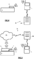
- a fixed or mobile reader L can read at short or medium range the identification data stored in the memory 21, and this same reader L can communicate the identification data to a database BD exploited by an infrastructure IN outside.
- a first attachment phase after the fixing of the first module 2 on the support S, in which the first module 3 is attached to the support S in a database BD exploited by the infrastructure IN, after reading by a reader L of the identification data stored in the memory 21 of the first module 2 and communication of this identification data by the reader L to the infrastructure IN.
- the controller 31 detects this coupling at the connector 35 and, in return, automatically transmits a coupling signal to the infrastructure IN.
- both modules 2, 3 are automatically associated with the same identification data and the same medium S in the database BD.
- the manual attachment is made only once during the first attachment phase, the fixing of the first module 2 on the support S. Then, only an automatic attachment is implemented in the second attachment phase, to the coupling of the second module 3 on the first module 2 (automatic commissioning).
- the connection between the memory 21 and the antenna 22 is made at least partly on an outer face of the housing 20 (the one that comes into contact with the support S), and this connection has a ruptible portion (which breaks beyond a given threshold force) which adheres to the support S.
- the ruptible portion breaks while remaining adhered to the support S, so that the connection is broken between the memory 21 and the antenna 22.
Description
La présente invention se rapporte à un système de radio-identification modulaire, et à un procédé d'assemblage d'un tel système de radio-identification modulaire.The present invention relates to a modular radio-identification system, and to a method of assembling such a modular radio-identification system.
L'invention se situe dans les domaines de l'identification, la localisation, la supervision et la surveillance d'objets ou de personnes à distance, au moyen des technologies de radio-identification dites RFID pour « Radio Frequency Identification ».The invention is in the field of identifying, locating, supervising and monitoring objects or people remotely, using RFID radio identification technologies for "Radio Frequency Identification".
En technologie RFID, trois modules (autrement nommés marqueur, balise ou transpondeur) de radio-identification sont connues, à savoir le module RFID passif, le module RFID actif et le module RFID semi-passif.In RFID technology, three modules (otherwise called marker, tag or transponder) of radio-identification are known, namely the passive RFID module, the active RFID module and the semi-passive RFID module.
Le module RFID passif, autrement appelé radio-étiquette, intègre simplement une mémoire, du type puce électronique, et une antenne reliée à la mémoire pour permettre la lecture à courte portée d'une donnée d'identification stockée dans la mémoire par un lecteur ; le lecteur étant constitué d'un émetteur radiofréquence qui active le module RFID passif en lui fournissant à courte distance l'énergie dont il a besoin pour communiquer sa donnée d'identification. Le module RFID passif permet ainsi la communication de la donnée d'identification à destination et à l'initiative d'une infrastructure extérieure, au moyen d'un lecteur à courte portée, typiquement jusqu'à une dizaine de mètre.The passive RFID module, otherwise known as a radio-tag, simply integrates a memory, of the electronic chip type, and an antenna connected to the memory to enable short-range reading of identification data stored in the memory by a reader; the reader being constituted by a radiofrequency transmitter which activates the passive RFID module by supplying it at a short distance the energy it needs to communicate its identification data. The passive RFID module thus allows the communication of the identification data to and at the initiative of an external infrastructure, by means of a short-range reader, typically up to ten meters.
Le module RFID actif intègre un contrôleur muni d'une mémoire et relié à une batterie d'alimentation et également à un émetteur/récepteur radiofréquence. Un module RFID actif permet l'identification, la supervision et éventuellement l'enregistrement de données de mesure en provenance d'un ou plusieurs capteurs équipant le module. Ce module RFID actif permet ainsi la communication de données (donnée d'identification stockée dans la mémoire et éventuellement données de mesure issues du ou des capteurs) à destination d'une infrastructure extérieure et à l'initiative du contrôleur du module qui envoie ces données à intervalle de temps régulier, avec une longue portée, typiquement d'une centaine de mètre.The active RFID module integrates a controller provided with a memory and connected to a battery pack and also to a radiofrequency transmitter / receiver. An active RFID module allows identification, supervision and possibly recording of measurement data from one or more sensors on the module. This active RFID module thus enables the communication of data (identification data stored in the memory and possibly measurement data from the sensor or sensors) to an external infrastructure and at the initiative of the controller of the module that sends the data. at a regular time interval, with a long range, typically a hundred meters.
Le module RFID semi-passif, aussi appelés « BAP tag » pour « Battery-Assisted Passive tag » ou marqueur passif assisté par batterie, combine la technologie RFID active et la technologie RFID passive, en intégrant une mémoire reliée à une antenne et à une batterie. Ainsi, la batterie permet d'augmenter la portée de lecture de la donnée d'identification stockée dans la mémoire par un lecteur à moyenne portée, typiquement jusqu'à quelques dizaines de mètres ; la communication entre le module RFID semi-passif et l'infrastructure extérieure se faisant à l'initiative de l'infrastructure comme dans la technologie passive, et non pas à l'initiative du module, sur une longue portée, typiquement d'une centaine de mètre.The semi-passive RFID module, also known as "BAP tag" for "Battery-Assisted Passive tag" or battery-powered passive marker, combines active RFID technology and passive RFID technology, integrating a memory connected to an antenna and a battery. Thus, the battery makes it possible to increase the reading range of the identification data stored in the memory by a medium-range reader, typically up to a few tens of meters; the communication between the semi-passive RFID module and the external infrastructure is at the initiative of the infrastructure as in passive technology, and not at the initiative of the module, over a long range, typically a hundred meter.
Les trois modules précités sont tous figés dans leurs technologies respectives, de sorte qu'il est nécessaire de recourir à deux modules distincts, à savoir un module RFID actif et un module RFID passif ou semi-passif, pour réaliser, d'un côté, une identification seule sur une longue période et, d'un autre côté, une identification, une supervision et un enregistrement sur une courte période.The three aforementioned modules are all fixed in their respective technologies, so that it is necessary to use two separate modules, namely an active RFID module and a passive or semi-passive RFID module, to realize, on one side, identification alone over a long period and, on the other hand, identification, supervision and registration over a short period.
En effet, il est parfois nécessaire de recourir à l'une ou l'autre des technologies RFID suivant les phases d'emploi des objets ou d'activité des personnes. A titre d'exemple, de nombreux objets dans différents domaines d'usage (eg. oeuvres d'art ou actifs industriels, objets de valeurs, échantillons et biens périssables) peuvent présenter des phases d'utilisation distinctes avec des besoins distincts :
- une phase de stockage sur une longue période (eg. sur plusieurs années) qui requiert uniquement de pouvoir identifier chaque objet au moyen de modules RFID passif voire semi-passif ;
- une phase de supervision sur de courtes périodes (eg. exposition temporaire des oeuvres d'art, usage d'actifs industriels pour la mise en oeuvre d'un procédé employé ponctuellement, transport) qui peut concerner certains des objets et qui requiert de pouvoir non seulement identifier, mais également superviser, surveiller avec des capteurs et localiser les objets en question au moyen de modules RFID actif.
- a storage phase over a long period (eg over several years) which only requires the ability to identify each object by means of passive or even semi-passive RFID modules;
- a phase of supervision over short periods (eg temporary exhibition of works of art, use of industrial assets for the implementation of a process used punctually, transport) which may concern some of the objects and which requires power not only identify, but also supervise, monitor with sensors and locate the objects in question by means of active RFID modules.
La seule technologie RFID passive ou semi-passive n'est pas adaptée pour les phases de supervision car elle ne permet pas de remplir les besoins de supervision et d'enregistrement de données mesurées par des capteurs ; aucune supervision n'est possible avec les modules RFID passif et semi-passif du fait de l'initiative de la communication par l'infrastructure.The only passive or semi-passive RFID technology is not suitable for supervision phases because it does not meet the need for supervision and recording of data measured by sensors; no supervision is possible with passive and semi-passive RFID modules due to the infrastructure communication initiative.
La seule technologie RFID active n'est quant à elle pas adaptée pour les phases de stockage car la gestion des batteries des multiples modules actifs est rédhibitoire en termes d'organisation et de coût ; ce problème se posant à moindre échelle avec les modules RFID semi-passif qui sont moins énergivore.The only active RFID technology is not adapted for the storage phases because the management of the batteries of the multiple active modules is prohibitive in terms of organization and cost; this problem is posing on a smaller scale with semi-passive RFID modules that are more energy efficient.
Il est donc classique de fixer sur les objets stockés des modules RFID passif qui ont l'avantage d'éviter une gestion des batteries pendant les longues phases de stockage et, pendant les courtes phases de supervision, de fixer temporairement sur les objets utilisés des modules RFID actif sans lien ni connexion avec les modules RFID passif.It is therefore conventional to fix on the stored objects passive RFID modules which have the advantage of avoiding battery management during the long storage phases and, during the short supervision phases, to fix temporarily on the objects used modules. RFID active without connection or connection with passive RFID modules.
Les inconvénients de procéder ainsi sont, premièrement, que la fixation de deux modules séparés sur un même objet pose des problèmes d'intrusion sur les objets, en particulier sur les objets fragiles et/ou de valeur comme les oeuvres d'art, et deuxièmement, la fixation d'un module RFID actif sur un objet est une opération chronophage et parfois complexe car on se fixe directement sur l'objet à surveiller.The disadvantages of doing so are, firstly, that the fixing of two separate modules on the same object poses problems of intrusion on the objects, in particular on fragile and / or valuable objects such as works of art, and secondly , fixing an active RFID module on an object is a time-consuming and sometimes complex operation because it is fixed directly on the object to be monitored.
En outre, il est nécessaire de doubler les opérations manuelles dites de rattachement ou « commissioning », avec un rattachement pour les modules RFID passif et un rattachement pour les modules RFID actif ; le rattachement consistant à rattacher ou associer un module à l'objet sur lequel il est fixé dans une base de données exploitée par l'infrastructure extérieure. Ce doublement des opérations de rattachement est bien entendu coûteux en temps de travail manuel, sans compter les risques d'erreur qui croissent avec le nombre d'opérations de rattachement.In addition, it is necessary to double the so-called manual operations or "commissioning", with an attachment for passive RFID modules and a connection for active RFID modules; the attachment consisting of attaching or associating a module to the object on which it is fixed in a database exploited by the external infrastructure. This doubling of the attachment operations is of course expensive in manual labor time, not to mention the risks of error that increase with the number of attachment operations.
De même, il est nécessaire de doubler les opérations manuelles dites de détachement ou « decommissioning » ; le détachement consistant à détacher ou désassocier un module à l'objet sur lequel il est fixé dans la base de données.Similarly, it is necessary to double the so-called manual detachment or "decommissioning" operations; the detachment of detaching or disassociating a module to the object on which it is fixed in the database.
De plus, avec les risques d'erreur inhérents aux opérations de rattachement, il n'est pas certain que les données de mesure de capteur transmises par un module RFID actif sont bien associées à l'objet auquel est rattaché le module RFID actif en question dans la base de données.Moreover, with the risks of error inherent in the attachment operations, it is not certain that the sensor measurement data transmitted by an active RFID module are well associated with the object to which the active RFID module in question is attached. in the database.
Enfin, dans le cas où un module RFID actif doit se comporter différemment selon l'objet sur lequel il est fixé, il est nécessaire de procéder à une programmation manuelle et coûteuse en temps, soit au niveau de l'infrastructure extérieure, soit au niveau du module RFID actif lui-même, à chaque utilisation du module RFID actif sur l'objet.Finally, in the case where an active RFID module must behave differently depending on the object on which it is fixed, it is necessary to carry out a manual programming and expensive in time, either at the level of the external infrastructure, or at the level of the active RFID module itself, with each use of the active RFID module on the object.
L'état de la technique peut également être illustré par les enseignements de la demande de brevet
L'état de la technique peut aussi être illustré par les enseignements de la demande de brevet
La présente invention a pour but de résoudre en tout ou partie les inconvénients précités, en proposant un système de radio-identification modulaire qui réduise les risques d'erreur de rattachement et de détachement, et qui offre à moindre coût une solution qui couvre toutes les phases d'utilisation du support à surveiller.The present invention aims to solve all or part of the aforementioned drawbacks, by proposing a modular radio-identification system which reduces the risks of mis-attachment and detachment, and which offers at a lower cost a solution that covers all phases of use of the medium to be monitored.
A cet effet, elle propose un système de radio-identification modulaire du type comprenant :
- un premier module de radio-identification passif comprenant un boîtier à l'intérieur duquel est disposé une mémoire de stockage d'une donnée d'identification reliée à une antenne ; et
- un second module de radio-identification actif comprenant un boîtier à l'intérieur duquel est disposé un contrôleur relié à une batterie d'alimentation, à un émetteur/récepteur radiofréquence et à au moins un capteur de mesure d'un paramètre physique ;
et les modules comprennent des moyens de connexion électrique adaptés pour établir une connexion électrique entre la mémoire du premier module et le contrôleur du second module une fois que le second module est fixé sur le premier module.For this purpose, it proposes a modular radio-identification system of the type comprising:
- a first passive radio-identification module comprising a housing inside which is disposed a storage memory of an identification data connected to an antenna; and
- a second active radio-identification module comprising a housing inside which is disposed a controller connected to a power supply battery, to a radiofrequency transceiver and to at least one sensor for measuring a physical parameter;
and the modules comprise electrical connection means adapted to establish an electrical connection between the memory of the first module and the controller of the second module once the second module is fixed on the first module.
Ainsi, l'invention propose un système modulaire permettant :
- la simple identification à courte distance du support (objet ou personne) au moyen du premier module RFID passif, ce premier module étant destiné à être fixé sur le support que l'on désire identifier en rattachant le premier module au support dans une base de données, pour satisfaire des besoins d'inventaire, de détection de présence à des points de lecture/écriture et/ou de sécurité antivol, le second module étant alors absent, autrement dit non accouplé au premier module ;
- l'identification à longue distance, la supervision, la localisation et la surveillance du support au moyen des premier et second modules accouplés, le second module permettant la mesure d'un ou plusieurs paramètres physiques de surveillance du support, et l'échange de données (donnée d'identification et données de mesure du ou des capteurs) à l'initiative du contrôleur du second module et sur une longue portée ; et
- éventuellement l'identification à moyenne distance du support si le premier module se voit équipé d'une batterie pour le convertir en module RFID semi-passif.
- the simple short-range identification of the medium (object or person) by means of the first passive RFID module, this first module being intended to be fixed on the medium that it is desired to identify by attaching the first module to the medium in a database , to satisfy inventory requirements, presence detection at reading / writing points and / or security antitheft, the second module then being absent, ie not coupled to the first module;
- long-range identification, supervision, location and monitoring of the medium using the coupled first and second modules, the second module for measuring one or more physical parameters of media monitoring, and data exchange (identification data and measurement data of the sensor or sensors) at the initiative of the controller of the second module and over a long range; and
- possibly the medium-range identification of the support if the first module is equipped with a battery to convert it into a semi-passive RFID module.
Grâce à l'invention, le second module ne comporte aucune donnée d'identification stockée par son contrôleur (hormis son numéro de série interne), et reste totalement générique. A l'accouplement entre les deux modules (accouplement mécanique et électrique), le second module est associé à la donnée d'identification du premier module, autrement dit le rattachement du second module avec le support s'effectue automatiquement à l'accouplement avec le premier module qui lui est porteur d'une donnée d'identification, permettant avantageusement de se passer d'une opération manuelle de rattachement du second module au support.Thanks to the invention, the second module has no identification data stored by its controller (except its internal serial number), and remains completely generic. At the coupling between the two modules (mechanical and electrical coupling), the second module is associated with the identification data of the first module, in other words the attachment of the second module with the support is carried out automatically at the coupling with the first module that carries an identification data, advantageously to do without a manual operation of attachment of the second module to the support.
En outre, grâce à l'invention, le second module est fixé physiquement sur le premier module, et non pas directement sur le support, simplifiant ainsi l'opération d'ancrage sur le support, sans compter que ce second module est tout d'abord associé au premier module (et non pas au support) avant d'être ensuite associé au support (lors du rattachement dans la base de données) via le premier module préalablement identifié et rattaché au support dans la base de données.In addition, thanks to the invention, the second module is physically fixed on the first module, and not directly on the support, thus simplifying the anchoring operation on the support, not to mention that this second module is all first associated with the first module (and not the support) before being subsequently associated with the support (when attached to the database) via the first module previously identified and attached to the support in the database.
De plus, une telle solution présente de nombreuses autres applications, comme par exemple :
- la possibilité de déclencher l'émission de signaux radio permettant de tracer des évènements de production/logisitique (notamment et à titre non limitatif des évènements du type demande de réapprovisionnement ou preuve de livraison) lors de la juxtaposition et/ou de la séparation des deux modules, de manière simple et en évitant toute transaction sur un système informatique ;
- la consultation via le premier module de données d'historique de juxtaposition ou de capteurs en provenance du second module.
- the possibility of triggering the emission of radio signals making it possible to trace production / logistic events (in particular and without limitation replenishment request type events or proof of delivery) when juxtaposing and / or separating the two modules, in a simple manner and avoiding any transaction on a computer system;
- consultation via the first juxtaposition history data module or sensors from the second module.
Ainsi, lorsque le second module n'est pas utilisé, on protège le premier module et ses moyens de connexion au moyen du capot amovible, ce capot étant fixé de manière réversible sur le premier module grâce aux mêmes moyens de fixation que ceux employés pour la fixation du second module sur le premier module.Thus, when the second module is not used, the first module and its connection means are protected by means of the removable cover, this cover being fixed reversibly to the first module by means of the same fastening means as those used for the first module. fixing the second module on the first module.
Dans une réalisation particulière, le capot intègre une batterie relié à des moyens de connexion électrique adaptés pour établir une connexion électrique avec les moyens de connexion du premier module une fois que le capot est fixé sur le premier module.In a particular embodiment, the cover incorporates a battery connected to electrical connection means adapted to establish an electrical connection with the connection means of the first module once the cover is fixed on the first module.
De cette manière, le capot équipé d'une batterie permet de convertir le premier module en un module RFID semi-passif, et ainsi accroître la portée de lecture.In this way, the hood equipped with a battery makes it possible to convert the first module into a semi-passive RFID module, and thus to increase the reading range.
De manière avantageuse, le premier module présente des moyens de fixation ménagés sur une portion de son boîtier qui ne vient pas en recouvrement complet de son antenne, de sorte que le second module ne recouvre pas complètement ladite antenne une fois que le second module est fixé sur le premier module.Advantageously, the first module has fastening means provided on a portion of its housing which does not completely overlap its antenna, so that the second module does not completely cover said antenna once the second module is fixed. on the first module.
Ainsi, le second module ne perturbe pas le rayonnement radio au niveau de l'antenne du premier module.Thus, the second module does not disturb the radio radiation at the antenna of the first module.
Selon une caractéristique, le boîtier du premier module présente une forme plate avec une épaisseur prédéterminée, et le boîtier du second module présente une encoche de réception du premier module ayant une profondeur équivalente à l'épaisseur du boîtier du premier module, où les moyens de fixation du second module sont ménagés dans ladite encoche.According to one feature, the housing of the first module has a flat shape with a predetermined thickness, and the housing of the second module has a receiving notch of the first module having a depth equivalent to the thickness of the housing of the first module, where the means of fixing the second module are formed in said notch.
Ainsi, le système complet (avec les deux modules accouplés) présente une épaisseur réduite sur le support, limitant ainsi l'encombrement.Thus, the complete system (with the two coupled modules) has a reduced thickness on the support, thus limiting the bulk.
Selon une autre caractéristique, les moyens de fixation sont des moyens de fixation par encliquetage, qui assurent un verrouillage mécanique entre les deux boîtiers.According to another characteristic, the fastening means are snap-fastening means, which provide mechanical locking between the two housings.
Dans une mode de réalisation particulier, le premier module intègre une connexion électrique entre la mémoire et l'antenne, ladite connexion étant réalisée au moins en partie sur une face externe du boîtier du premier module et présentant une partie ruptible pourvue de moyens d'adhésion sur le support.In a particular embodiment, the first module integrates an electrical connection between the memory and the antenna, said connection being made at least partly on an outer face of the housing of the first module and having a ruptible portion provided with adhesion means on the support.
Ainsi, une fois que le premier module est fixé sur le support, ladite partie ruptible adhère au support. Si on procède au retrait du premier module, la partie ruptible reste adhérée sur le support et la connexion électrique entre la mémoire et l'antenne est rompue, rendant inopérant le premier module.Thus, once the first module is fixed on the support, said ruptible portion adheres to the support. If the first module is removed, the ruptible part remains adhered to the support and the electrical connection between the memory and the antenna is broken, rendering the first module inoperative.
L'invention se rapporte également à un procédé d'assemblage d'un système de radio-identification modulaire conforme à l'invention, comprenant une phase de fixation du premier module sur un support, notamment un objet ou une personne, suivie d'une phase d'accouplement du second module sur le premier module avec :
- la fixation des boîtiers par coopération entre leurs moyens de fixation respectifs, et
- la connexion entre la mémoire du premier module et le contrôleur du second module par contact entre les moyens de connexion électrique.
- fastening the housings by cooperation between their respective fastening means, and
- the connection between the memory of the first module and the controller of the second module by contact between the electrical connection means.
Selon une possibilité de l'invention, suite à la phase d'accouplement, le contrôleur émet automatiquement un signal d'accouplement, pour informer ainsi une infrastructure extérieure de l'accouplement.According to a possibility of the invention, following the coupling phase, the controller automatically transmits a coupling signal, thus informing an external infrastructure of the coupling.
Selon une autre possibilité de l'invention, le procédé comprend en outre les phases de rattachement suivantes :
- une première phase de rattachement, entre la phase de fixation et la phase d'accouplement, dans laquelle on rattache le premier module au support dans une base de données exploitée par une infrastructure extérieure, avec une étape de lecture par l'infrastructure extérieure de la donnée d'identification stockée dans la mémoire du premier module ;
- une seconde phase de rattachement, après la phase d'accouplement, dans laquelle on rattache le second module au support dans la même base de données, avec le contrôleur du second module qui récupère la donnée d'identification stockée dans la mémoire du premier module et qui communique cette donnée d'identification à destination de l'infrastructure extérieure, de sorte que les premier et second modules sont associés à la même donnée d'identification et au même support dans la base de données.
- a first phase of attachment, between the fixing phase and the coupling phase, in which the first module is attached to the support in a database operated by an external infrastructure, with a reading step by the external infrastructure of the identification data stored in the memory of the first module;
- a second attachment phase, after the coupling phase, in which the second module is attached to the support in the same database, with the controller of the second module which retrieves the identification data stored in the memory of the first module and which communicates this identification data to the external infrastructure, so that the first and second modules are associated with the same identification data and the same medium in the database.
Autrement dit, et comme expliqué ci-dessus, le rattachement du second module se fait automatiquement à l'accouplement entre les modules, avec une donnée d'identification commune aux deux modules pour l'infrastructure extérieure, fiabilisant et simplifiant ainsi le rattachement du second module au support.In other words, and as explained above, the attachment of the second module is done automatically to the coupling between the modules, with an identification data common to the two modules for the external infrastructure, making it more reliable and thus simplifying the attachment of the second module. module to support.
Le procédé d'assemblage peut également comprendre successivement :
- une phase de désaccouplement du second module vis-à-vis du premier module, le premier module restant fixé sur le support, avec la séparation entre les boîtiers et la déconnexion entre la mémoire du premier module et le contrôleur du second module,
- une phase de détachement dans laquelle on détache le second module du support dans la base de données, avec le contrôleur du second module qui communique automatiquement une donnée de détachement à destination de l'infrastructure extérieure suite à la déconnexion dudit contrôleur avec la mémoire du premier module.
- a phase of uncoupling of the second module vis-à-vis the first module, the first module remaining fixed on the support, with the separation between the boxes and the disconnection between the memory of the first module and the controller of the second module,
- a detachment phase in which the second module of the medium is detached from the database, with the controller of the second module which automatically communicates detachment data to the external infrastructure following the disconnection of said controller with the memory of the first module.
Ainsi, le détachement du second module se fait également de façon automatique, sans opération manuelle et sans risque d'erreur dans la base de données.Thus, the detachment of the second module is also done automatically, without manual operation and without risk of error in the database.
Il est également envisageable que, avant la phase d'accouplement, on stocke dans la mémoire du premier module des données relatives au support et/ou des paramètres de fonctionnement du second module, et ensuite, après la phase d'accouplement, le contrôleur lit automatiquement ces données relatives au support et/ou ces paramètres relatifs au second module via la connexion électrique entre les deux modules pour une supervision du support par le second module adaptée aux caractéristiques dudit support et dudit second module.It is also conceivable that, before the coupling phase, data in the memory of the first module are stored relative to the medium and / or operating parameters of the second module, and then, after the coupling phase, the controller reads automatically this data relating to the medium and / or these parameters relating to the second module via the electrical connection between the two modules for a supervision of the support by the second module adapted to the characteristics of said support and said second module.
Ainsi, sans avoir à intervenir sur le second module ou sur l'infrastructure extérieure, le second module récupère dès l'accouplement avec le premier module les données relatives au support, pour une supervision en adéquation avec les caractéristiques du support. Par exemple, ces données relatives au support vont avoir une influence sur le contrôleur dans la gestion du ou des capteurs, la gestion d'éventuelles alertes, la gestion des communications par l'émetteur/récepteur radiofréquence, notamment sur la périodicité des envois à destination de l'infrastructure extérieure.Thus, without having to intervene on the second module or on the external infrastructure, the second module retrieves, upon coupling with the first module, the data relating to the medium, for a supervision in adequacy with the characteristics of the medium. For example, this data relating to the medium will have an influence on the controller in the management of the sensor (s), the management of possible alerts, the management of communications by the radiofrequency transmitter / receiver, in particular on the periodicity of the sendings to the external infrastructure.
En outre, ce procédé d'assemblage peut se conclure par une phase de retrait du premier module vis-à-vis du support, ledit retrait rendant automatiquement ledit premier module inopérant, évitant ainsi à l'infrastructure extérieure de prendre en compte ce premier module qui n'est plus attaché à un support.In addition, this assembly method can be concluded by a withdrawal phase of the first module vis-à-vis the support, said withdrawal automatically rendering said first module inoperative, thus avoiding the external infrastructure to take into account this first module who is no longer attached to a support.
D'autres caractéristiques et avantages de la présente invention apparaîtront à la lecture de la description détaillée ci-après, d'un exemple de mise en oeuvre non limitatif, faite en référence aux figures annexées dans lesquelles :
- les
figures 1 sont des vues schématiques d'un système conforme à l'invention, respectivement avant et après accouplement entre les deux modules ;et 2 - la
figure 3 est une vue schématique du premier module du système desfigures 1 , avec un capot de protection ;et 2 - la
figure 4 est une vue schématique d'une première utilisation du système conforme à l'invention, avec uniquement le premier module fixé sur un objet ; et - la
figure 5 est une vue schématique d'une seconde utilisation du système conforme à l'invention, avec les deux modules accouplés.
- the
Figures 1 and 2 are schematic views of a system according to the invention, respectively before and after coupling between the two modules; - the
figure 3 is a schematic view of the first module of the system ofFigures 1 and 2 , with a protective cover; - the
figure 4 is a schematic view of a first use of the system according to the invention, with only the first module attached to an object; and - the
figure 5 is a schematic view of a second use of the system according to the invention, with the two modules coupled.
En référence aux
Le premier module 2 comporte un boîtier 20 à l'intérieur duquel sont disposées une mémoire 21 de stockage d'une donnée d'identification et autres paramètres propres au premier module 2, et une antenne 22 en liaison avec la mémoire 21. Le premier module 2 intègre également un connecteur électrique 23 disposé sur l'extérieur du boîtier 20 et en liaison avec la mémoire 21. Le boîtier 20 présente également des moyens de fixation 24 réversible (ou amovible), notamment du type moyen de fixation par encliquetage. Ces moyens de fixation 24 sont prévus sur une portion du boîtier 20, sans recouvrement de l'antenne 22. Le connecteur électrique 23 est prévu sur cette même portion du boîtier 20. Le boîtier 20 présente une forme plate avec une épaisseur prédéterminée, de préférence inférieure à 3 millimètres.The
Le second module 3 comporte un boîtier 30 à l'intérieur duquel sont disposés un contrôleur 31 (notamment du type microcontrôleur), une batterie 32 d'alimentation électrique relié au contrôleur 31, un émetteur/récepteur radiofréquence 33 relié au contrôleur 31, et au moins un capteur 34 de mesure d'un paramètre physique (comme par exemple un accéléromètre, un capteur de température, un capteur d'humidité, un capteur de contact, un capteur de pression, etc.) relié au contrôleur 31. L'émetteur/récepteur radiofréquence 33 est notamment adapté à tout type d'infrastructure radio fixe ou mobile et, à titre d'exemple non limitatif, fonctionne selon des normes de communication UHF, GSM, Wifi, Bluetooth, 3G, Zigbee ou toutes autres normes de communication sans fil.The
Le second module 3 intègre également un connecteur électrique 35 disposé sur l'extérieur du boîtier 30 et en liaison avec le contrôleur 31. Le boîtier 30 présente également une trappe (non illustrée) d'accès à la batterie 32 pour permettre son remplacement. Le boîtier 30 présente également des moyens de fixation 36 réversible qui sont complémentaires des moyens de fixation 24 du boîtier 20, afin de permettre la fixation réversible du boîtier 30 sur le boîtier 20 par coopération entre les moyens de fixation 24, 36, en particulier par coopération de forme et élasticité dans le cas de moyens de fixation par encliquetage. Le boîtier 30 présente une forme plate avec une épaisseur prédéterminée supérieure à celle du boîtier 20 et de préférence inférieure à 5 millimètres. Le boîtier 30 présente une encoche 37 de réception du boîtier 20, les moyens de fixation 36 étant prévus dans cette encoche 37, et cette encoche 37 présente une profondeur équivalente à l'épaisseur du boîtier 20. L'encoche 37 est suffisamment courte pour ne pas recouvrir complètement l'antenne 22, afin que le second module 3 ne recouvre complètement pas l'antenne 22 et permette la communication entre un lecteur L et le premier module 2.The
En référence à la
De manière optionnelle, ce capot 4 intègre une batterie 41 relié à un connecteur électrique 42 adaptés pour établir une connexion électrique avec le connecteur électrique 23 du premier module 2 une fois que le capot 4 est fixé sur le premier module 2. Ainsi, la batterie 41 peut alimenter électriquement le premier module 2, de sorte que l'ensemble premier module 2/capot 4 forme un module RFID semi-passif.Optionally, this
Dans une première utilisation illustrée schématiquement sur la
Dans une seconde utilisation illustrée schématiquement sur la
- on fixe le boîtier 30 sur le boîtier 20 par coopération entre leurs moyens de
fixation - on connecte la mémoire 21 du
premier module 2 et le contrôleur 31 dusecond module 3 par contact entre leurs connecteurs 23, 35.
- the
housing 30 is fixed on thehousing 20 by cooperation between their respective fixing means 24, 36, and concomitantly - the
memory 21 of thefirst module 2 and thecontroller 31 of thesecond module 3 are connected by contact between theirconnectors
Une fois les deux modules 2, 3 accouplés, le contrôleur 31 détecte ce couplage au niveau du connecteur 35 et, en retour, émet automatiquement un signal d'accouplement à destination de l'infrastructure IN.Once the two
En outre, une fois les deux modules 2, 3 accouplés, est mis en oeuvre une seconde phase de rattachement dans laquelle on rattache le second module 3 au support S dans la même base de données BD, avec le contrôleur 31 qui récupère la donnée d'identification stockée dans la mémoire 21 du premier module 2 et qui communique de sa propre initiative cette donnée d'identification à destination de l'infrastructure via un réseau de télécommunication RT grâce à son émetteur/récepteur 33. Ainsi, les deux modules 2, 3 sont associés automatiquement à la même donnée d'identification et au même support S dans la base de données BD.In addition, once the two
Ainsi, le rattachement manuel ne se fait qu'une seule fois lors de la première phase de rattachement, à la fixation du premier module 2 sur le support S. Ensuite, seul un rattachement automatique est mis en oeuvre dans la seconde phase de rattachement, à l'accouplement du second module 3 sur le premier module 2 (« commissioning » automatique).Thus, the manual attachment is made only once during the first attachment phase, the fixing of the
Pour prendre en compte des caractéristiques intrinsèques du support S dans le pilotage mis en oeuvre par le contrôleur 31, il est envisageable de prévoir :
- avant la phase d'accouplement, on stocke dans la mémoire 21 du
premier module 2 des données relatives au support S (caractéristiques intrinsèques du support S), avec de préférence un stockage sécurisé pour éviter tout paramétrage mal intentionné ; et ensuite - après la phase d'accouplement, le contrôleur 31 lit automatiquement ces données relatives au support S dans la mémoire 21 (de préférence après vérification de l'intégrité de ces données) pour pouvoir ainsi, de manière automatique et sans intervention sur le contrôleur 31 et sur l'infrastructure IN, établir une supervision du support S adaptée aux caractéristiques du support S.
- before the coupling phase, the data relating to the medium S (intrinsic characteristics of the medium S) are stored in the
memory 21 of thefirst module 2, preferably with a secure storage to avoid any ill-intentioned parameterization; and then - after the coupling phase, the
controller 31 automatically reads this data relating to the medium S in the memory 21 (preferably after verification of the integrity of this data) so as to be able, automatically and without intervention on thecontroller 31 and on the IN infrastructure, establish a supervision of the support S adapted to the characteristics of the support S.
Lorsque le besoin du second module 3 n'est plus présent, sont mise en oeuvre les étapes successives suivantes :
- on désaccouple le
second module 3 vis-à-vis dupremier module 2,le premier module 2 restant toujours fixé sur le support S, en procédant à la séparation entre les boîtiers 20, 30 qui entraîne la déconnexion entre les deux connecteurs 23, 35 ; puis - on détache automatiquement le
second module 3 du support S dans la base de données BD, avec le contrôleur 31 qui communique automatiquement une donnée de détachement à destination de l'infrastructure IN (suite à la déconnexion entre le contrôleur 31 la mémoire 21 du premier module 2), et l'infrastructure IN procède en réponse au détachement (« decommissioning » automatique).
- the
second module 3 is uncoupled from thefirst module 2, thefirst module 2 still being fixed on the support S, by separating thehousings connectors - the
second module 3 of the support S is automatically detached in the database BD, with thecontroller 31 which automatically communicates detachment data to the infrastructure IN (following the disconnection between thecontroller 31 thememory 21 of the first module 2), and the IN infrastructure responds to automatic decommissioning.
Il est également à noter que si on procédé à un retrait physique du premier module 2 vis-à-vis du support S, ce retrait rend automatiquement le premier module 2 inopérant, en particulier avec un retrait qui provoquerait un arrachement ou une scission d'une connexion entre la mémoire 21 et l'antenne 22. Dans ce cas, la connexion entre la mémoire 21 et l'antenne 22 est réalisée au moins en partie sur une face externe du boîtier 20 (celle qui vient en contact avec le support S), et cette connexion présente une partie ruptible (qui se rompt au-delà d'un effort seuil donné) qui adhère au support S. Ainsi, lors du retrait du premier module 2, la partie ruptible se rompt en restant adhérée au support S, de sorte que la connexion est rompue entre la mémoire 21 et l'antenne 22.It should also be noted that if a physical removal of the
Bien entendu l'exemple de mise en oeuvre évoqué ci-dessus ne présente aucun caractère limitatif et d'autres améliorations et détails peuvent être apportés au système selon l'invention, sans pour autant sortir du cadre de l'invention où d'autres formes de moyen de fixation peuvent par exemple être réalisées.Of course the implementation example mentioned above is not limiting in nature and further improvements and details can be made to the system according to the invention, without departing from the scope of the invention where other forms fixing means may for example be made.
Claims (13)
- A modular radio-identification system (1) of the type comprising:- a first module (2) for passive radio-identification comprising a casing (20) inside which is disposed a memory (21) for storing an identification data linked to an antenna (22); andsaid system (1) being characterized in that it further comprises:- a second module (3) for active radio-identification comprising a casing (30) inside which is disposed a controller (31) linked to a supply battery (32), to a radio frequency transmitter/receiver (33) and to at least one sensor (34) for measuring a physical parameter;wherein the casings (20, 30) of both modules (2, 3) are equipped with reversible and complementary fastening means (24, 36) adapted to cooperate together in order to enable the reversible fastening of the second module (3) on the first module (2);
and the modules (2, 3) comprise electrical connection means (23, 35) adapted to establish an electrical connection between the memory (21) of the first module (2) and the controller (31) of the second module (3) once the second module (3) is fastened on the first module (2). - The system (1) according to claim 1, further comprising a cowl (4) for covering the first module (2), said cowl (4) comprising reversible fastening means (40) adapted to cooperate with the fastening means (24) of the casing (20) of said first module (2), said cowl (4) covering the connection means (23) of the first module (2) once the cowl (4) is fastened on the first module (2).
- The system (1) according to claim 2, wherein said cowl (4) integrates a battery (41) linked to electrical connection means (42) adapted to establish an electrical connection with the connection means (23) of the first module (2) once the cowl is fastened on the first module (2).
- The system (1) according to any one of the preceding claims, wherein the first module (2) has fastening means (24) arranged on a portion of its casing (20) which does not completely cover its antenna (22), so that the second module (3) does not completely cover said antenna (22) once the second module (3) is fastened on the first module (2).
- The system (1) according to any one of the preceding claims, wherein the casing (20) of the first module (2) has a flat shape with a predetermined thickness, and the casing (30) of the second module (3) has a notch (37) for receiving the first module (2) having a depth equivalent to the thickness of the casing (20) of the first module (2), where the fastening means (36) of the second module (3) are arranged in said notch (37).
- The system (1) according to any one of the preceding claims, wherein the fastening means (24, 36) are snap-fastening means.
- The system (1) according to any one of the preceding claims, wherein the first module (2) integrates an electrical connection between the memory (21) and the antenna (22), said connection being carried out at least partly on an external face of the casing (20) of the first module (2) and having a breakable part provided with adhesion means on the support (S).
- A method for assembling a system (1) in accordance with any one of the preceding claims, comprising a fastening phase of the first module (2) on a support (S), particularly an object or a person, followed by a coupling phase of the second module (3) on the first module (2) with:- the fastening of the casings (20, 30) by cooperation between their respective fastening means (24, 36), and- the connection between the memory (21) of the first module (2) and the controller (31) of the second module (3) by contact between the electrical connection means (23, 35).
- An assembly method according to claim 8, wherein, following the coupling phase, the controller (31) automatically transmits a coupling signal.
- The assembly method according to claim 8 or 9, comprising the following attachment phases:- a first attachment phase, between the fastening phase and the coupling phase, wherein the first module (2) is attached to the support (S) in a database (BD) operated by an outer infrastructure (IN), with a reading step by the outer infrastructure (IN) of the identification data stored in the memory (21) of the first module (2);- a second attachment phase, after the coupling phase, wherein the second module (3) is attached to the support (S) in the same database (BD), with the controller (31) of the second module (3) retrieving the identification data stored in the memory (21) of the first module (2) and communicating this identification data to the outer infrastructure (IN), so that the first and the second modules (2, 3) are associated with the same identification data and to the same support (S) in the database (BD).
- The assembly method according to claim 10, comprising successively:- a decoupling phase of the second module (3) vis-à-vis the first module (2), the first module (2) remaining fastened on the support (S), with the separation between the casings (20, 30) and the disconnection between the memory (21) of the first module (2) and the controller (31) of the second module (3),- a detachment phase wherein the second module (3) of the support (S) is detached in the database (BD), with the controller (31) of the second module (3) automatically communicating a detachment data to the outer infrastructure (IN) following the disconnection of said controller (31) with the memory (21) of the first module (2).
- The assembly method according to any one of claims 8 to 11, wherein, before the coupling phase, data related to the support (S) are stored in the memory (21) of the first module (2), and then, after the coupling phase, the controller (31) automatically reads these data related to the support (S) via the electrical connection between the two modules (2, 3) for a supervision of the support (S) by the second module (3) adapted to the characteristics of said support (S).
- The assembly method according to any one of claims 8 to 12, comprising a removal phase of the first module (2) vis-à-vis the support (S), said removal making said first module (2) automatically inoperative.
Applications Claiming Priority (2)
| Application Number | Priority Date | Filing Date | Title |
|---|---|---|---|
| FR1355106A FR3006479B1 (en) | 2013-06-04 | 2013-06-04 | MODULAR RADIOIDENTIFICATION SYSTEM WITH PASSIVE RFID MODULE AND ACTIVE RFID MODULE |
| PCT/FR2014/051268 WO2014195609A1 (en) | 2013-06-04 | 2014-05-28 | Modular radio-identification system with passive rfid module and active rfid module |
Publications (2)
| Publication Number | Publication Date |
|---|---|
| EP3005246A1 EP3005246A1 (en) | 2016-04-13 |
| EP3005246B1 true EP3005246B1 (en) | 2018-05-02 |
Family
ID=49111390
Family Applications (1)
| Application Number | Title | Priority Date | Filing Date |
|---|---|---|---|
| EP14731752.3A Active EP3005246B1 (en) | 2013-06-04 | 2014-05-28 | Modulares rfid-system mit passiven rfid-modul und activen rfid-modul |
Country Status (5)
| Country | Link |
|---|---|
| US (1) | US9589223B2 (en) |
| EP (1) | EP3005246B1 (en) |
| ES (1) | ES2681621T3 (en) |
| FR (1) | FR3006479B1 (en) |
| WO (1) | WO2014195609A1 (en) |
Families Citing this family (4)
| Publication number | Priority date | Publication date | Assignee | Title |
|---|---|---|---|---|
| RU183103U1 (en) * | 2018-05-28 | 2018-09-19 | Федеральное государственное автономное образовательное учреждение высшего образования "Санкт-Петербургский государственный электротехнический университет "ЛЭТИ" им. В.И. Ульянова (Ленина)" | Wireless motion sensor |
| RU193924U1 (en) * | 2019-07-09 | 2019-11-21 | федеральное государственное автономное образовательное учреждение высшего образования "Национальный исследовательский университет ИТМО" (Университет ИТМО) | BATTERY-FREE COMMUNICATION MODULE |
| EP3869408A1 (en) * | 2020-02-20 | 2021-08-25 | Hewlett-Packard Development Company, L.P. | 3d-printed components with rfid connection detection |
| WO2023242910A1 (en) * | 2022-06-13 | 2023-12-21 | 日本電信電話株式会社 | Wireless communication device and wireless communication method |
Family Cites Families (4)
| Publication number | Priority date | Publication date | Assignee | Title |
|---|---|---|---|---|
| JP4516525B2 (en) * | 2003-04-25 | 2010-08-04 | シャープ株式会社 | Tag and management method and management system using the same |
| US20090227299A1 (en) * | 2008-03-10 | 2009-09-10 | Samsung Electronics Co., Ltd. | System and method for providing interchangeable modules for a mobile station |
| CN101996335B (en) * | 2010-11-30 | 2013-04-10 | 重庆梅安森科技股份有限公司 | Intrinsically safe type personal identification locator based on double-frequency RFID |
| JP5874075B2 (en) * | 2011-11-16 | 2016-03-01 | 北川工業株式会社 | Non-contact IC tag |
-
2013
- 2013-06-04 FR FR1355106A patent/FR3006479B1/en not_active Expired - Fee Related
-
2014
- 2014-05-28 EP EP14731752.3A patent/EP3005246B1/en active Active
- 2014-05-28 ES ES14731752.3T patent/ES2681621T3/en active Active
- 2014-05-28 WO PCT/FR2014/051268 patent/WO2014195609A1/en active Application Filing
- 2014-05-28 US US14/896,319 patent/US9589223B2/en active Active
Non-Patent Citations (1)
| Title |
|---|
| None * |
Also Published As
| Publication number | Publication date |
|---|---|
| FR3006479A1 (en) | 2014-12-05 |
| WO2014195609A1 (en) | 2014-12-11 |
| EP3005246A1 (en) | 2016-04-13 |
| US9589223B2 (en) | 2017-03-07 |
| ES2681621T3 (en) | 2018-09-14 |
| US20160162768A1 (en) | 2016-06-09 |
| FR3006479B1 (en) | 2015-06-19 |
Similar Documents
| Publication | Publication Date | Title |
|---|---|---|
| US10689882B2 (en) | Tamper evident cargo container seal bolt lock | |
| EP3005246B1 (en) | Modulares rfid-system mit passiven rfid-modul und activen rfid-modul | |
| KR101696378B1 (en) | Mobile wireless network for asset tracking and supply chain monitoring | |
| US10815694B2 (en) | Tamper evident cargo container seal bolt lock | |
| CN111149008A (en) | System and method for utilizing battery operational data and exogenous data | |
| EP3119619B1 (en) | Mounting patch for a tyre | |
| CA2727994A1 (en) | Communicating apparatus and equipment logging method | |
| EP3465548B1 (en) | Sealing system and method of installing a sealing system | |
| CN104573973A (en) | Historical relic monitoring and protecting system and method based on RFID technology | |
| EP3499421A1 (en) | Module with rfid transponder for communicating information to a reading device | |
| FR2928763A1 (en) | SYSTEM FOR MONITORING AT LEAST ONE DEVICE INTENDED FOR TRANSPORT | |
| FR3004564A1 (en) | IDENTIFICATION MARKER | |
| Ekanayake et al. | Smart protector: A real-time theft prevention system for transportation management | |
| CN204480303U (en) | A kind of historical relic monitor protective system based on RFID technique | |
| CN215117583U (en) | Logistics packaging box | |
| CN113516422A (en) | A containing box for commodity circulation storage | |
| EP2993632A1 (en) | Tracking of objects on board a transport unit |
Legal Events
| Date | Code | Title | Description |
|---|---|---|---|
| PUAI | Public reference made under article 153(3) epc to a published international application that has entered the european phase |
Free format text: ORIGINAL CODE: 0009012 |
|
| 17P | Request for examination filed |
Effective date: 20151221 |
|
| AK | Designated contracting states |
Kind code of ref document: A1 Designated state(s): AL AT BE BG CH CY CZ DE DK EE ES FI FR GB GR HR HU IE IS IT LI LT LU LV MC MK MT NL NO PL PT RO RS SE SI SK SM TR |
|
| AX | Request for extension of the european patent |
Extension state: BA ME |
|
| DAX | Request for extension of the european patent (deleted) | ||
| 17Q | First examination report despatched |
Effective date: 20170127 |
|
| GRAP | Despatch of communication of intention to grant a patent |
Free format text: ORIGINAL CODE: EPIDOSNIGR1 |
|
| INTG | Intention to grant announced |
Effective date: 20171211 |
|
| GRAS | Grant fee paid |
Free format text: ORIGINAL CODE: EPIDOSNIGR3 |
|
| GRAA | (expected) grant |
Free format text: ORIGINAL CODE: 0009210 |
|
| AK | Designated contracting states |
Kind code of ref document: B1 Designated state(s): AL AT BE BG CH CY CZ DE DK EE ES FI FR GB GR HR HU IE IS IT LI LT LU LV MC MK MT NL NO PL PT RO RS SE SI SK SM TR |
|
| REG | Reference to a national code |
Ref country code: GB Ref legal event code: FG4D Free format text: NOT ENGLISH |
|
| REG | Reference to a national code |
Ref country code: CH Ref legal event code: EP Ref country code: AT Ref legal event code: REF Ref document number: 996038 Country of ref document: AT Kind code of ref document: T Effective date: 20180515 |
|
| REG | Reference to a national code |
Ref country code: DE Ref legal event code: R096 Ref document number: 602014024859 Country of ref document: DE |
|
| REG | Reference to a national code |
Ref country code: IE Ref legal event code: FG4D Free format text: LANGUAGE OF EP DOCUMENT: FRENCH |
|
| REG | Reference to a national code |
Ref country code: FR Ref legal event code: PLFP Year of fee payment: 5 |
|
| REG | Reference to a national code |
Ref country code: CH Ref legal event code: NV Representative=s name: CABINET GERMAIN AND MAUREAU, CH |
|
| REG | Reference to a national code |
Ref country code: NL Ref legal event code: MP Effective date: 20180502 |
|
| REG | Reference to a national code |
Ref country code: ES Ref legal event code: FG2A Ref document number: 2681621 Country of ref document: ES Kind code of ref document: T3 Effective date: 20180914 |
|
| REG | Reference to a national code |
Ref country code: LT Ref legal event code: MG4D |
|
| PG25 | Lapsed in a contracting state [announced via postgrant information from national office to epo] |
Ref country code: LT Free format text: LAPSE BECAUSE OF FAILURE TO SUBMIT A TRANSLATION OF THE DESCRIPTION OR TO PAY THE FEE WITHIN THE PRESCRIBED TIME-LIMIT Effective date: 20180502 Ref country code: SE Free format text: LAPSE BECAUSE OF FAILURE TO SUBMIT A TRANSLATION OF THE DESCRIPTION OR TO PAY THE FEE WITHIN THE PRESCRIBED TIME-LIMIT Effective date: 20180502 Ref country code: FI Free format text: LAPSE BECAUSE OF FAILURE TO SUBMIT A TRANSLATION OF THE DESCRIPTION OR TO PAY THE FEE WITHIN THE PRESCRIBED TIME-LIMIT Effective date: 20180502 Ref country code: BG Free format text: LAPSE BECAUSE OF FAILURE TO SUBMIT A TRANSLATION OF THE DESCRIPTION OR TO PAY THE FEE WITHIN THE PRESCRIBED TIME-LIMIT Effective date: 20180802 Ref country code: NO Free format text: LAPSE BECAUSE OF FAILURE TO SUBMIT A TRANSLATION OF THE DESCRIPTION OR TO PAY THE FEE WITHIN THE PRESCRIBED TIME-LIMIT Effective date: 20180802 |
|
| PG25 | Lapsed in a contracting state [announced via postgrant information from national office to epo] |
Ref country code: GR Free format text: LAPSE BECAUSE OF FAILURE TO SUBMIT A TRANSLATION OF THE DESCRIPTION OR TO PAY THE FEE WITHIN THE PRESCRIBED TIME-LIMIT Effective date: 20180803 Ref country code: HR Free format text: LAPSE BECAUSE OF FAILURE TO SUBMIT A TRANSLATION OF THE DESCRIPTION OR TO PAY THE FEE WITHIN THE PRESCRIBED TIME-LIMIT Effective date: 20180502 Ref country code: RS Free format text: LAPSE BECAUSE OF FAILURE TO SUBMIT A TRANSLATION OF THE DESCRIPTION OR TO PAY THE FEE WITHIN THE PRESCRIBED TIME-LIMIT Effective date: 20180502 Ref country code: NL Free format text: LAPSE BECAUSE OF FAILURE TO SUBMIT A TRANSLATION OF THE DESCRIPTION OR TO PAY THE FEE WITHIN THE PRESCRIBED TIME-LIMIT Effective date: 20180502 Ref country code: LV Free format text: LAPSE BECAUSE OF FAILURE TO SUBMIT A TRANSLATION OF THE DESCRIPTION OR TO PAY THE FEE WITHIN THE PRESCRIBED TIME-LIMIT Effective date: 20180502 |
|
| REG | Reference to a national code |
Ref country code: AT Ref legal event code: MK05 Ref document number: 996038 Country of ref document: AT Kind code of ref document: T Effective date: 20180502 |
|
| REG | Reference to a national code |
Ref country code: BE Ref legal event code: MM Effective date: 20180531 |
|
| PG25 | Lapsed in a contracting state [announced via postgrant information from national office to epo] |
Ref country code: AT Free format text: LAPSE BECAUSE OF FAILURE TO SUBMIT A TRANSLATION OF THE DESCRIPTION OR TO PAY THE FEE WITHIN THE PRESCRIBED TIME-LIMIT Effective date: 20180502 Ref country code: RO Free format text: LAPSE BECAUSE OF FAILURE TO SUBMIT A TRANSLATION OF THE DESCRIPTION OR TO PAY THE FEE WITHIN THE PRESCRIBED TIME-LIMIT Effective date: 20180502 Ref country code: CZ Free format text: LAPSE BECAUSE OF FAILURE TO SUBMIT A TRANSLATION OF THE DESCRIPTION OR TO PAY THE FEE WITHIN THE PRESCRIBED TIME-LIMIT Effective date: 20180502 Ref country code: SK Free format text: LAPSE BECAUSE OF FAILURE TO SUBMIT A TRANSLATION OF THE DESCRIPTION OR TO PAY THE FEE WITHIN THE PRESCRIBED TIME-LIMIT Effective date: 20180502 Ref country code: EE Free format text: LAPSE BECAUSE OF FAILURE TO SUBMIT A TRANSLATION OF THE DESCRIPTION OR TO PAY THE FEE WITHIN THE PRESCRIBED TIME-LIMIT Effective date: 20180502 Ref country code: PL Free format text: LAPSE BECAUSE OF FAILURE TO SUBMIT A TRANSLATION OF THE DESCRIPTION OR TO PAY THE FEE WITHIN THE PRESCRIBED TIME-LIMIT Effective date: 20180502 Ref country code: DK Free format text: LAPSE BECAUSE OF FAILURE TO SUBMIT A TRANSLATION OF THE DESCRIPTION OR TO PAY THE FEE WITHIN THE PRESCRIBED TIME-LIMIT Effective date: 20180502 |
|
| REG | Reference to a national code |
Ref country code: DE Ref legal event code: R097 Ref document number: 602014024859 Country of ref document: DE |
|
| REG | Reference to a national code |
Ref country code: IE Ref legal event code: MM4A |
|
| PG25 | Lapsed in a contracting state [announced via postgrant information from national office to epo] |
Ref country code: SM Free format text: LAPSE BECAUSE OF FAILURE TO SUBMIT A TRANSLATION OF THE DESCRIPTION OR TO PAY THE FEE WITHIN THE PRESCRIBED TIME-LIMIT Effective date: 20180502 |
|
| PLBE | No opposition filed within time limit |
Free format text: ORIGINAL CODE: 0009261 |
|
| STAA | Information on the status of an ep patent application or granted ep patent |
Free format text: STATUS: NO OPPOSITION FILED WITHIN TIME LIMIT |
|
| PG25 | Lapsed in a contracting state [announced via postgrant information from national office to epo] |
Ref country code: LU Free format text: LAPSE BECAUSE OF NON-PAYMENT OF DUE FEES Effective date: 20180528 Ref country code: MC Free format text: LAPSE BECAUSE OF FAILURE TO SUBMIT A TRANSLATION OF THE DESCRIPTION OR TO PAY THE FEE WITHIN THE PRESCRIBED TIME-LIMIT Effective date: 20180502 |
|
| 26N | No opposition filed |
Effective date: 20190205 |
|
| PG25 | Lapsed in a contracting state [announced via postgrant information from national office to epo] |
Ref country code: IE Free format text: LAPSE BECAUSE OF NON-PAYMENT OF DUE FEES Effective date: 20180528 |
|
| PG25 | Lapsed in a contracting state [announced via postgrant information from national office to epo] |
Ref country code: SI Free format text: LAPSE BECAUSE OF FAILURE TO SUBMIT A TRANSLATION OF THE DESCRIPTION OR TO PAY THE FEE WITHIN THE PRESCRIBED TIME-LIMIT Effective date: 20180502 Ref country code: BE Free format text: LAPSE BECAUSE OF NON-PAYMENT OF DUE FEES Effective date: 20180531 |
|
| PG25 | Lapsed in a contracting state [announced via postgrant information from national office to epo] |
Ref country code: AL Free format text: LAPSE BECAUSE OF FAILURE TO SUBMIT A TRANSLATION OF THE DESCRIPTION OR TO PAY THE FEE WITHIN THE PRESCRIBED TIME-LIMIT Effective date: 20180502 |
|
| PG25 | Lapsed in a contracting state [announced via postgrant information from national office to epo] |
Ref country code: MT Free format text: LAPSE BECAUSE OF FAILURE TO SUBMIT A TRANSLATION OF THE DESCRIPTION OR TO PAY THE FEE WITHIN THE PRESCRIBED TIME-LIMIT Effective date: 20180502 |
|
| PG25 | Lapsed in a contracting state [announced via postgrant information from national office to epo] |
Ref country code: TR Free format text: LAPSE BECAUSE OF FAILURE TO SUBMIT A TRANSLATION OF THE DESCRIPTION OR TO PAY THE FEE WITHIN THE PRESCRIBED TIME-LIMIT Effective date: 20180502 |
|
| PG25 | Lapsed in a contracting state [announced via postgrant information from national office to epo] |
Ref country code: PT Free format text: LAPSE BECAUSE OF FAILURE TO SUBMIT A TRANSLATION OF THE DESCRIPTION OR TO PAY THE FEE WITHIN THE PRESCRIBED TIME-LIMIT Effective date: 20180502 |
|
| PG25 | Lapsed in a contracting state [announced via postgrant information from national office to epo] |
Ref country code: CY Free format text: LAPSE BECAUSE OF FAILURE TO SUBMIT A TRANSLATION OF THE DESCRIPTION OR TO PAY THE FEE WITHIN THE PRESCRIBED TIME-LIMIT Effective date: 20180502 Ref country code: MK Free format text: LAPSE BECAUSE OF NON-PAYMENT OF DUE FEES Effective date: 20180502 Ref country code: HU Free format text: LAPSE BECAUSE OF FAILURE TO SUBMIT A TRANSLATION OF THE DESCRIPTION OR TO PAY THE FEE WITHIN THE PRESCRIBED TIME-LIMIT; INVALID AB INITIO Effective date: 20140528 |
|
| PG25 | Lapsed in a contracting state [announced via postgrant information from national office to epo] |
Ref country code: IS Free format text: LAPSE BECAUSE OF FAILURE TO SUBMIT A TRANSLATION OF THE DESCRIPTION OR TO PAY THE FEE WITHIN THE PRESCRIBED TIME-LIMIT Effective date: 20180902 |
|
| PGFP | Annual fee paid to national office [announced via postgrant information from national office to epo] |
Ref country code: IT Payment date: 20230523 Year of fee payment: 10 Ref country code: FR Payment date: 20230428 Year of fee payment: 10 Ref country code: ES Payment date: 20230607 Year of fee payment: 10 Ref country code: DE Payment date: 20230428 Year of fee payment: 10 Ref country code: CH Payment date: 20230602 Year of fee payment: 10 |
|
| PGFP | Annual fee paid to national office [announced via postgrant information from national office to epo] |
Ref country code: GB Payment date: 20230530 Year of fee payment: 10 |