EP3005246B1 - Modular rfid system with passif rfid module and active rfid module - Google Patents
Modular rfid system with passif rfid module and active rfid module Download PDFInfo
- Publication number
- EP3005246B1 EP3005246B1 EP14731752.3A EP14731752A EP3005246B1 EP 3005246 B1 EP3005246 B1 EP 3005246B1 EP 14731752 A EP14731752 A EP 14731752A EP 3005246 B1 EP3005246 B1 EP 3005246B1
- Authority
- EP
- European Patent Office
- Prior art keywords
- module
- support
- phase
- memory
- controller
- Prior art date
- Legal status (The legal status is an assumption and is not a legal conclusion. Google has not performed a legal analysis and makes no representation as to the accuracy of the status listed.)
- Active
Links
Images

Classifications
-
- G—PHYSICS
- G06—COMPUTING; CALCULATING OR COUNTING
- G06K—GRAPHICAL DATA READING; PRESENTATION OF DATA; RECORD CARRIERS; HANDLING RECORD CARRIERS
- G06K19/00—Record carriers for use with machines and with at least a part designed to carry digital markings
- G06K19/06—Record carriers for use with machines and with at least a part designed to carry digital markings characterised by the kind of the digital marking, e.g. shape, nature, code
- G06K19/067—Record carriers with conductive marks, printed circuits or semiconductor circuit elements, e.g. credit or identity cards also with resonating or responding marks without active components
- G06K19/07—Record carriers with conductive marks, printed circuits or semiconductor circuit elements, e.g. credit or identity cards also with resonating or responding marks without active components with integrated circuit chips
- G06K19/0723—Record carriers with conductive marks, printed circuits or semiconductor circuit elements, e.g. credit or identity cards also with resonating or responding marks without active components with integrated circuit chips the record carrier comprising an arrangement for non-contact communication, e.g. wireless communication circuits on transponder cards, non-contact smart cards or RFIDs
-
- G—PHYSICS
- G06—COMPUTING; CALCULATING OR COUNTING
- G06K—GRAPHICAL DATA READING; PRESENTATION OF DATA; RECORD CARRIERS; HANDLING RECORD CARRIERS
- G06K19/00—Record carriers for use with machines and with at least a part designed to carry digital markings
- G06K19/06—Record carriers for use with machines and with at least a part designed to carry digital markings characterised by the kind of the digital marking, e.g. shape, nature, code
- G06K19/067—Record carriers with conductive marks, printed circuits or semiconductor circuit elements, e.g. credit or identity cards also with resonating or responding marks without active components
- G06K19/07—Record carriers with conductive marks, printed circuits or semiconductor circuit elements, e.g. credit or identity cards also with resonating or responding marks without active components with integrated circuit chips
- G06K19/077—Constructional details, e.g. mounting of circuits in the carrier
- G06K19/07737—Constructional details, e.g. mounting of circuits in the carrier the record carrier consisting of two or more mechanically separable parts
-
- G—PHYSICS
- G06—COMPUTING; CALCULATING OR COUNTING
- G06F—ELECTRIC DIGITAL DATA PROCESSING
- G06F16/00—Information retrieval; Database structures therefor; File system structures therefor
- G06F16/20—Information retrieval; Database structures therefor; File system structures therefor of structured data, e.g. relational data
- G06F16/24—Querying
- G06F16/245—Query processing
- G06F16/24569—Query processing with adaptation to specific hardware, e.g. adapted for using GPUs or SSDs
-
- G—PHYSICS
- G06—COMPUTING; CALCULATING OR COUNTING
- G06K—GRAPHICAL DATA READING; PRESENTATION OF DATA; RECORD CARRIERS; HANDLING RECORD CARRIERS
- G06K19/00—Record carriers for use with machines and with at least a part designed to carry digital markings
- G06K19/06—Record carriers for use with machines and with at least a part designed to carry digital markings characterised by the kind of the digital marking, e.g. shape, nature, code
- G06K19/067—Record carriers with conductive marks, printed circuits or semiconductor circuit elements, e.g. credit or identity cards also with resonating or responding marks without active components
- G06K19/07—Record carriers with conductive marks, printed circuits or semiconductor circuit elements, e.g. credit or identity cards also with resonating or responding marks without active components with integrated circuit chips
- G06K19/0701—Record carriers with conductive marks, printed circuits or semiconductor circuit elements, e.g. credit or identity cards also with resonating or responding marks without active components with integrated circuit chips at least one of the integrated circuit chips comprising an arrangement for power management
- G06K19/0702—Record carriers with conductive marks, printed circuits or semiconductor circuit elements, e.g. credit or identity cards also with resonating or responding marks without active components with integrated circuit chips at least one of the integrated circuit chips comprising an arrangement for power management the arrangement including a battery
-
- G—PHYSICS
- G06—COMPUTING; CALCULATING OR COUNTING
- G06K—GRAPHICAL DATA READING; PRESENTATION OF DATA; RECORD CARRIERS; HANDLING RECORD CARRIERS
- G06K19/00—Record carriers for use with machines and with at least a part designed to carry digital markings
- G06K19/06—Record carriers for use with machines and with at least a part designed to carry digital markings characterised by the kind of the digital marking, e.g. shape, nature, code
- G06K19/067—Record carriers with conductive marks, printed circuits or semiconductor circuit elements, e.g. credit or identity cards also with resonating or responding marks without active components
- G06K19/07—Record carriers with conductive marks, printed circuits or semiconductor circuit elements, e.g. credit or identity cards also with resonating or responding marks without active components with integrated circuit chips
- G06K19/077—Constructional details, e.g. mounting of circuits in the carrier
- G06K19/0772—Physical layout of the record carrier
-
- G—PHYSICS
- G06—COMPUTING; CALCULATING OR COUNTING
- G06K—GRAPHICAL DATA READING; PRESENTATION OF DATA; RECORD CARRIERS; HANDLING RECORD CARRIERS
- G06K19/00—Record carriers for use with machines and with at least a part designed to carry digital markings
- G06K19/06—Record carriers for use with machines and with at least a part designed to carry digital markings characterised by the kind of the digital marking, e.g. shape, nature, code
- G06K19/067—Record carriers with conductive marks, printed circuits or semiconductor circuit elements, e.g. credit or identity cards also with resonating or responding marks without active components
- G06K19/07—Record carriers with conductive marks, printed circuits or semiconductor circuit elements, e.g. credit or identity cards also with resonating or responding marks without active components with integrated circuit chips
- G06K19/077—Constructional details, e.g. mounting of circuits in the carrier
- G06K19/07749—Constructional details, e.g. mounting of circuits in the carrier the record carrier being capable of non-contact communication, e.g. constructional details of the antenna of a non-contact smart card
-
- G—PHYSICS
- G06—COMPUTING; CALCULATING OR COUNTING
- G06K—GRAPHICAL DATA READING; PRESENTATION OF DATA; RECORD CARRIERS; HANDLING RECORD CARRIERS
- G06K7/00—Methods or arrangements for sensing record carriers, e.g. for reading patterns
- G06K7/10—Methods or arrangements for sensing record carriers, e.g. for reading patterns by electromagnetic radiation, e.g. optical sensing; by corpuscular radiation
- G06K7/10009—Methods or arrangements for sensing record carriers, e.g. for reading patterns by electromagnetic radiation, e.g. optical sensing; by corpuscular radiation sensing by radiation using wavelengths larger than 0.1 mm, e.g. radio-waves or microwaves
- G06K7/10297—Methods or arrangements for sensing record carriers, e.g. for reading patterns by electromagnetic radiation, e.g. optical sensing; by corpuscular radiation sensing by radiation using wavelengths larger than 0.1 mm, e.g. radio-waves or microwaves arrangements for handling protocols designed for non-contact record carriers such as RFIDs NFCs, e.g. ISO/IEC 14443 and 18092
Definitions
- the present invention relates to a modular radio-identification system, and to a method of assembling such a modular radio-identification system.
- the invention is in the field of identifying, locating, supervising and monitoring objects or people remotely, using RFID radio identification technologies for "Radio Frequency Identification”.
- the passive RFID module In RFID technology, three modules (otherwise called marker, tag or transponder) of radio-identification are known, namely the passive RFID module, the active RFID module and the semi-passive RFID module.
- the passive RFID module simply integrates a memory, of the electronic chip type, and an antenna connected to the memory to enable short-range reading of identification data stored in the memory by a reader; the reader being constituted by a radiofrequency transmitter which activates the passive RFID module by supplying it at a short distance the energy it needs to communicate its identification data.
- the passive RFID module thus allows the communication of the identification data to and at the initiative of an external infrastructure, by means of a short-range reader, typically up to ten meters.
- the active RFID module integrates a controller provided with a memory and connected to a battery pack and also to a radiofrequency transmitter / receiver.
- An active RFID module allows identification, supervision and possibly recording of measurement data from one or more sensors on the module. This active RFID module thus enables the communication of data (identification data stored in the memory and possibly measurement data from the sensor or sensors) to an external infrastructure and at the initiative of the controller of the module that sends the data. at a regular time interval, with a long range, typically a hundred meters.
- the semi-passive RFID module also known as "BAP tag” for “Battery-Assisted Passive tag” or battery-powered passive marker, combines active RFID technology and passive RFID technology, integrating a memory connected to an antenna and a battery.
- the battery makes it possible to increase the reading range of the identification data stored in the memory by a medium-range reader, typically up to a few tens of meters; the communication between the semi-passive RFID module and the external infrastructure is at the initiative of the infrastructure as in passive technology, and not at the initiative of the module, over a long range, typically a hundred meter.
- the three aforementioned modules are all fixed in their respective technologies, so that it is necessary to use two separate modules, namely an active RFID module and a passive or semi-passive RFID module, to realize, on one side, identification alone over a long period and, on the other hand, identification, supervision and registration over a short period.
- the only passive or semi-passive RFID technology is not suitable for supervision phases because it does not meet the need for supervision and recording of data measured by sensors; no supervision is possible with passive and semi-passive RFID modules due to the infrastructure communication initiative.
- the only active RFID technology is not adapted for the storage phases because the management of the batteries of the multiple active modules is prohibitive in terms of organization and cost; this problem is posing on a smaller scale with semi-passive RFID modules that are more energy efficient.
- the present invention aims to solve all or part of the aforementioned drawbacks, by proposing a modular radio-identification system which reduces the risks of mis-attachment and detachment, and which offers at a lower cost a solution that covers all phases of use of the medium to be monitored.
- the second module has no identification data stored by its controller (except its internal serial number), and remains completely generic.
- the second module is associated with the identification data of the first module, in other words the attachment of the second module with the support is carried out automatically at the coupling with the first module that carries an identification data, advantageously to do without a manual operation of attachment of the second module to the support.
- the second module is physically fixed on the first module, and not directly on the support, thus simplifying the anchoring operation on the support, not to mention that this second module is all first associated with the first module (and not the support) before being subsequently associated with the support (when attached to the database) via the first module previously identified and attached to the support in the database.
- the first module and its connection means are protected by means of the removable cover, this cover being fixed reversibly to the first module by means of the same fastening means as those used for the first module. fixing the second module on the first module.
- the cover incorporates a battery connected to electrical connection means adapted to establish an electrical connection with the connection means of the first module once the cover is fixed on the first module.
- the hood equipped with a battery makes it possible to convert the first module into a semi-passive RFID module, and thus to increase the reading range.
- the first module has fastening means provided on a portion of its housing which does not completely overlap its antenna, so that the second module does not completely cover said antenna once the second module is fixed. on the first module.
- the second module does not disturb the radio radiation at the antenna of the first module.
- the housing of the first module has a flat shape with a predetermined thickness
- the housing of the second module has a receiving notch of the first module having a depth equivalent to the thickness of the housing of the first module, where the means of fixing the second module are formed in said notch.
- the complete system (with the two coupled modules) has a reduced thickness on the support, thus limiting the bulk.
- the fastening means are snap-fastening means, which provide mechanical locking between the two housings.
- the first module integrates an electrical connection between the memory and the antenna, said connection being made at least partly on an outer face of the housing of the first module and having a ruptible portion provided with adhesion means on the support.
- said ruptible portion adheres to the support. If the first module is removed, the ruptible part remains adhered to the support and the electrical connection between the memory and the antenna is broken, rendering the first module inoperative.
- the controller automatically transmits a coupling signal, thus informing an external infrastructure of the coupling.
- the attachment of the second module is done automatically to the coupling between the modules, with an identification data common to the two modules for the external infrastructure, making it more reliable and thus simplifying the attachment of the second module. module to support.
- the detachment of the second module is also done automatically, without manual operation and without risk of error in the database.
- the second module retrieves, upon coupling with the first module, the data relating to the medium, for a supervision in adequacy with the characteristics of the medium.
- this data relating to the medium will have an influence on the controller in the management of the sensor (s), the management of possible alerts, the management of communications by the radiofrequency transmitter / receiver, in particular on the periodicity of the sendings to the external infrastructure.
- this assembly method can be concluded by a withdrawal phase of the first module vis-à-vis the support, said withdrawal automatically rendering said first module inoperative, thus avoiding the external infrastructure to take into account this first module who is no longer attached to a support.
- a modular radio identification system 1 comprises a first passive radio-identification module 2 and a second active radio-identification module 3.
- the first module 2 comprises a housing 20 inside which are disposed a memory 21 for storing an identification data and other parameters specific to the first module 2, and an antenna 22 in connection with the memory 21.
- the first module 2 also includes an electrical connector 23 disposed on the outside of the housing 20 and in connection with the memory 21.
- the housing 20 also has reversible (or removable) fastening means 24, in particular of the snap-fastening type. These fixing means 24 are provided on a portion of the housing 20, without covering the antenna 22.
- the electrical connector 23 is provided on the same portion of the housing 20.
- the housing 20 has a flat shape with a predetermined thickness, preferably less than 3 millimeters.
- the second module 3 comprises a housing 30 inside which are arranged a controller 31 (in particular of the microcontroller type), a power supply battery 32 connected to the controller 31, a radiofrequency transmitter / receiver 33 connected to the controller 31, and less a sensor 34 for measuring a physical parameter (such as for example an accelerometer, a temperature sensor, a humidity sensor, a contact sensor, a pressure sensor, etc.) connected to the controller 31.
- the transmitter / radio frequency receiver 33 is particularly suitable for any type of fixed or mobile radio infrastructure and, by way of non-limiting example, operates according to UHF communication standards, GSM, Wifi, Bluetooth, 3G, Zigbee or any other communication standards wireless.
- the second module 3 also includes an electrical connector 35 disposed on the outside of the housing 30 and in connection with the controller 31.
- the housing 30 also has a hatch (not shown) access to the battery 32 to allow its replacement.
- the housing 30 also has reversible fixing means 36 which are complementary to the fixing means 24 of the housing 20, in order to allow the reversible attachment of the housing 30 to the housing 20 by cooperation between the fixing means 24, 36, in particular by shape and elasticity cooperation in the case of snap-fastening means.
- the housing 30 has a flat shape with a predetermined thickness greater than that of the housing 20 and preferably less than 5 millimeters.
- the housing 30 has a notch 37 for receiving the housing 20, the fastening means 36 being provided in this notch 37, and this notch 37 has a depth equivalent to the thickness of the housing 20.
- the notch 37 is sufficiently short to not completely cover the antenna 22 so that the second module 3 does not completely cover the antenna 22 and allows communication between a reader L and the first module 2.
- the first module 2 may be covered by a protective cover 4, intended mainly for the protection of the electrical connector 23 in the absence of the second module 3.
- This cover 4 of the first module 2 cover comprises reversible fixing means 40 adapted to cooperate with the fastening means 24 of the housing 20, so that the cover 4 is fixed on the first module 2 in the same manner as the second module 3.
- this cover 4 covers the electrical connector 23 once fixed on the first module 2.
- this cover 4 includes a battery 41 connected to an electrical connector 42 adapted to establish an electrical connection with the electrical connector 23 of the first module 2 once the cover 4 is fixed on the first module 2.
- the battery 41 can electrically power the first module 2, so that the first module 2 / cover assembly 4 forms a semi-passive RFID module.
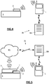
- a fixed or mobile reader L can read at short or medium range the identification data stored in the memory 21, and this same reader L can communicate the identification data to a database BD exploited by an infrastructure IN outside.
- a first attachment phase after the fixing of the first module 2 on the support S, in which the first module 3 is attached to the support S in a database BD exploited by the infrastructure IN, after reading by a reader L of the identification data stored in the memory 21 of the first module 2 and communication of this identification data by the reader L to the infrastructure IN.
- the controller 31 detects this coupling at the connector 35 and, in return, automatically transmits a coupling signal to the infrastructure IN.
- both modules 2, 3 are automatically associated with the same identification data and the same medium S in the database BD.
- the manual attachment is made only once during the first attachment phase, the fixing of the first module 2 on the support S. Then, only an automatic attachment is implemented in the second attachment phase, to the coupling of the second module 3 on the first module 2 (automatic commissioning).
- the connection between the memory 21 and the antenna 22 is made at least partly on an outer face of the housing 20 (the one that comes into contact with the support S), and this connection has a ruptible portion (which breaks beyond a given threshold force) which adheres to the support S.
- the ruptible portion breaks while remaining adhered to the support S, so that the connection is broken between the memory 21 and the antenna 22.
Landscapes
- Engineering & Computer Science (AREA)
- Theoretical Computer Science (AREA)
- Physics & Mathematics (AREA)
- General Physics & Mathematics (AREA)
- Computer Hardware Design (AREA)
- Microelectronics & Electronic Packaging (AREA)
- Health & Medical Sciences (AREA)
- Computer Networks & Wireless Communication (AREA)
- Toxicology (AREA)
- Data Mining & Analysis (AREA)
- Databases & Information Systems (AREA)
- General Engineering & Computer Science (AREA)
- Computational Linguistics (AREA)
- Computer Security & Cryptography (AREA)
- Electromagnetism (AREA)
- General Health & Medical Sciences (AREA)
- Artificial Intelligence (AREA)
- Computer Vision & Pattern Recognition (AREA)
- Arrangements For Transmission Of Measured Signals (AREA)
Claims (13)
- Modulares Funkidentifikationssystem (1) desjenigen Typs, der umfasst:- ein erstes passives Funkidentifikationsmodul (2), das ein Gehäuse (20) umfasst, in dessen Inneren ein an eine Antenne (22) angeschlossener Speicher (21) zum Speichern einer Identifikationsinformation angeordnet ist; undwobei das System (1) dadurch gekennzeichnet ist, dass es weiter umfasst:- ein zweites aktives Funkidentifikationsmodul (3), das ein Gehäuse (30) umfasst, in dessen Inneren eine Steuerung (31) angeordnet ist, die an eine Versorgungsbatterie (32), an einen Funkfrequenz-Sender/Empfänger (33) und an mindestens einen Sensor (34) zum Messen eines physikalischen Parameters angeschlossen ist;wobei die Gehäuse (20, 30) der zwei Module (2, 3) mit reversiblen und komplementären Befestigungsmitteln (24, 36) ausgestattet sind, die dafür ausgebildet sind, zusammenzuwirken, um das reversible Befestigen des zweiten Moduls (3) auf dem ersten Modul (2) zu ermöglichen;
und die Module (2, 3) elektrische Verbindungsmittel (23, 35) umfassen, die dafür ausgebildet sind, eine elektrische Verbindung zwischen dem Speicher (21) des ersten Moduls (2) und der Steuerung (31) des zweiten Moduls (3) herzustellen, sobald das zweite Module (3) auf dem ersten Modul (2) befestigt wird. - System (1) nach Anspruch 1, weiter eine Haube (4) zum Abdecken des ersten Moduls (2) umfassend, wobei die Haube (4) reversible Befestigungsmittel (40) umfasst, die dafür ausgebildet sind, mit den Befestigungsmitteln (24) des Gehäuses (20) des ersten Moduls (2) zusammenzuwirken, wobei die Haube (4) die Verbindungsmittel (23) des ersten Moduls (2) abdeckt, sobald die Haube (4) auf dem ersten Modul (2) befestigt wird.
- System (1) nach Anspruch 2, wobei die Haube (4) eine Batterie (41) enthält, die an elektrische Verbindungsmittel (42) angeschlossen ist, die dafür ausgebildet sind, eine elektrische Verbindung zu den Verbindungsmitteln (23) des ersten Moduls (2) herzustellen, sobald die Haube auf dem ersten Modul (2) befestigt wird.
- System (1) nach einem der vorstehenden Ansprüche, wobei das erste Modul (2) Befestigungsmittel (24) aufweist, die an einem Abschnitt seines Gehäuses (20) ausgeformt sind, der nicht vollständig in Abdeckung seiner Antenne (22) geht, sodass das zweite Modul (3) die Antenne (22) nicht vollständig abdeckt, sobald das zweite Modul (3) auf dem ersten Modul (2) befestigt wird.
- System (1) nach einem der vorstehenden Ansprüche, wobei das Gehäuse (20) des ersten Moduls (2) eine flache Form mit einer vorbestimmten Dicke aufweist, und das Gehäuse (30) des zweiten Moduls (3) eine Aussparung (37) zum Aufnehmen des ersten Moduls (2) aufweist, die eine der Dicke des Gehäuses (20) des ersten Moduls (2) entsprechende Tiefe besitzt, wobei die Befestigungsmittel (36) des zweiten Moduls (3) in der Aussparung (37) ausgeformt sind.
- System (1) nach einem der vorstehenden Ansprüche, wobei die Befestigungsmittel (24, 36) Mittel zur Befestigung durch Einklicken sind.
- System (1) nach einem der vorstehenden Ansprüche, wobei das erste Modul (2) eine elektrische Verbindung zwischen dem Speicher (21) und der Antenne (22) enthält, wobei die Verbindung mindestens zum Teil auf einer Außenfläche des Gehäuses (20) des ersten Moduls (2) ausgeführt ist und einen reißfähigen Teil aufweist, der mit Mitteln zum Festkleben auf dem Träger (S) versehen ist.
- Verfahren zum Zusammenbauen eines Systems (1) gemäß einem der vorstehenden Ansprüche, umfassend eine Phase des Befestigens des ersten Moduls (2) auf einem Träger (S), insbesondere einem Gegenstand oder einer Person, gefolgt von einer Phase des Ankoppelns des zweiten Moduls (3) auf dem ersten Modul (2) mit:- dem Befestigen der Gehäuse (20, 30) durch Zusammenwirken zwischen ihren jeweiligen Befestigungsmitteln (24, 36), und- dem Verbinden zwischen dem Speicher (21) des ersten Moduls (2) und der Steuerung (31) des zweiten Moduls (3) durch Kontakt zwischen den elektrischen Verbindungsmitteln (23, 35).
- Zusammenbauverfahren nach Anspruch 8, wobei im Anschluss an die Ankopplungsphase die Steuerung (31) automatisch ein Ankopplungssignal ausgibt.
- Zusammenbauverfahren nach den Ansprüchen 8 oder 9, umfassend die folgenden Verknüpfungsphasen:- eine erste Verknüpfungsphase zwischen der Befestigungsphase und der Ankopplungsphase, in der mit einem Schritt des Lesens der im Speicher (21) des ersten Moduls (2) gespeicherten Identifikationsinformation durch die externe Infrastruktur (IN) das erste Modul (2) in einer von einer externen Infrastruktur (IN) betriebenen Datenbank (BD) mit dem Träger (S) verknüpft wird;- eine zweite Verknüpfungsphase nach der Ankopplungsphase, in der mit der Steuerung (31) des zweiten Moduls (3), die die im Speicher (21) des ersten Moduls (2) gespeicherte Identifikationsinformation abruft und die diese Identifikationsinformation an die externe Infrastruktur (IN) kommuniziert, das zweite Modul (3) in der gleichen Datenbank (BD) so mit dem Träger (S) verknüpft wird, dass das erste und zweite Modul (2, 3) in der Datenbank (BD) der gleichen Identifikationsinformation und dem gleichen Träger (S) zugeordnet sind.
- Zusammenbauverfahren nach Anspruch 10, nacheinander umfassend:- eine Phase des Abkoppelns des zweiten Moduls (3) vom ersten Modul (2), wobei mit der Trennung zwischen den Gehäusen (20, 30) und dem Trennen der Verbindung zwischen dem Speicher (21) des ersten Moduls (2) und der Steuerung (31) des zweiten Moduls (3) das erste Modul (2) auf dem Träger (S) befestigt bleibt,- eine Phase des Entknüpfens, in der mit der Steuerung (31) des zweiten Moduls (3), die im Anschluss an das Trennen der Verbindung der Steuerung (31) zum Speicher (21) des ersten Moduls (2) automatisch eine Entknüpfungsinformation an die externe Infrastruktur (IN) kommuniziert, das zweite Modul (3) in der Datenbank (BD) vom Träger (S) entknüpft wird.
- Zusammenbauverfahren nach einem der Ansprüche 8 bis 11, wobei vor der Ankopplungsphase auf den Träger (S) bezogene Daten im Speicher (21) des ersten Moduls (2) gespeichert werden, und anschließend nach der Ankopplungsphase die Steuerung (31) diese auf den Träger (S) bezogenen Daten über die elektrische Verbindung zwischen den zwei Modulen (2, 3) automatisch liest, für eine auf die Merkmale des Trägers (S) abgestimmte Überwachung des Trägers (S) durch das zweite Modul (3).
- Zusammenbauverfahren nach einem der Ansprüche 8 bis 12, umfassend eine Phase des Entfernens des ersten Moduls (2) vom Träger (S), wobei das Entfernen das erste Modul (2) automatisch infunktional macht.
Applications Claiming Priority (2)
| Application Number | Priority Date | Filing Date | Title |
|---|---|---|---|
| FR1355106A FR3006479B1 (fr) | 2013-06-04 | 2013-06-04 | Systeme de radio-identification modulaire avec module rfid passif et module rfid actif |
| PCT/FR2014/051268 WO2014195609A1 (fr) | 2013-06-04 | 2014-05-28 | Système de radio-identification modulaire avec module rfid passif et module rfid actif |
Publications (2)
| Publication Number | Publication Date |
|---|---|
| EP3005246A1 EP3005246A1 (de) | 2016-04-13 |
| EP3005246B1 true EP3005246B1 (de) | 2018-05-02 |
Family
ID=49111390
Family Applications (1)
| Application Number | Title | Priority Date | Filing Date |
|---|---|---|---|
| EP14731752.3A Active EP3005246B1 (de) | 2013-06-04 | 2014-05-28 | Modular rfid system with passif rfid module and active rfid module |
Country Status (5)
| Country | Link |
|---|---|
| US (1) | US9589223B2 (de) |
| EP (1) | EP3005246B1 (de) |
| ES (1) | ES2681621T3 (de) |
| FR (1) | FR3006479B1 (de) |
| WO (1) | WO2014195609A1 (de) |
Families Citing this family (4)
| Publication number | Priority date | Publication date | Assignee | Title |
|---|---|---|---|---|
| RU183103U1 (ru) * | 2018-05-28 | 2018-09-19 | Федеральное государственное автономное образовательное учреждение высшего образования "Санкт-Петербургский государственный электротехнический университет "ЛЭТИ" им. В.И. Ульянова (Ленина)" | Беспроводной датчик перемещения |
| RU193924U1 (ru) * | 2019-07-09 | 2019-11-21 | федеральное государственное автономное образовательное учреждение высшего образования "Национальный исследовательский университет ИТМО" (Университет ИТМО) | Коммуникационный модуль с безбатарейным питанием |
| EP3869408A1 (de) * | 2020-02-20 | 2021-08-25 | Hewlett-Packard Development Company, L.P. | 3d-gedruckte komponenten mit detektion von rfid-verbindung |
| WO2023242910A1 (ja) * | 2022-06-13 | 2023-12-21 | 日本電信電話株式会社 | 無線通信装置及び無線通信方法 |
Family Cites Families (4)
| Publication number | Priority date | Publication date | Assignee | Title |
|---|---|---|---|---|
| DE602004029458D1 (de) * | 2003-04-25 | 2010-11-18 | Sharp Kk | Etikett, system und verfahren zur verwaltung einer warenverteilung |
| US20090227299A1 (en) * | 2008-03-10 | 2009-09-10 | Samsung Electronics Co., Ltd. | System and method for providing interchangeable modules for a mobile station |
| CN101996335B (zh) * | 2010-11-30 | 2013-04-10 | 重庆梅安森科技股份有限公司 | 基于双频rfid的本安型人员识别定位仪 |
| JP5874075B2 (ja) * | 2011-11-16 | 2016-03-01 | 北川工業株式会社 | 非接触icタグ |
-
2013
- 2013-06-04 FR FR1355106A patent/FR3006479B1/fr not_active Expired - Fee Related
-
2014
- 2014-05-28 US US14/896,319 patent/US9589223B2/en active Active
- 2014-05-28 ES ES14731752.3T patent/ES2681621T3/es active Active
- 2014-05-28 WO PCT/FR2014/051268 patent/WO2014195609A1/fr active Application Filing
- 2014-05-28 EP EP14731752.3A patent/EP3005246B1/de active Active
Non-Patent Citations (1)
| Title |
|---|
| None * |
Also Published As
| Publication number | Publication date |
|---|---|
| ES2681621T3 (es) | 2018-09-14 |
| FR3006479A1 (fr) | 2014-12-05 |
| WO2014195609A1 (fr) | 2014-12-11 |
| US9589223B2 (en) | 2017-03-07 |
| FR3006479B1 (fr) | 2015-06-19 |
| US20160162768A1 (en) | 2016-06-09 |
| EP3005246A1 (de) | 2016-04-13 |
Similar Documents
| Publication | Publication Date | Title |
|---|---|---|
| US10689882B2 (en) | Tamper evident cargo container seal bolt lock | |
| EP3005246B1 (de) | Modular rfid system with passif rfid module and active rfid module | |
| US10815694B2 (en) | Tamper evident cargo container seal bolt lock | |
| KR101696378B1 (ko) | 자산 추적 및 공급 체인 모니터링을 위한 모바일 무선 네트워크 | |
| EP3119619B1 (de) | Montageflicken für einen reifen | |
| CA2727994A1 (fr) | Dispositif communicant et procede de consignation d'un equipement | |
| EP3465548B1 (de) | Dichtungssystem und verfahren zur installation eines dichtungssystems | |
| CN104573973A (zh) | 一种基于rfid技术的文物监控保护系统及方法 | |
| EP3499421A1 (de) | Rfid-transpondermodul für eine kommunikation von informationen an eine lesevorrichtung | |
| FR2928763A1 (fr) | Systeme de suivi d'au moins un dispositif destine a etre transporte | |
| Ekanayake et al. | Smart protector: A real-time theft prevention system for transportation management | |
| FR3004564A1 (fr) | Marqueur d'identification | |
| CN204480303U (zh) | 一种基于rfid技术的文物监控保护系统 | |
| FR3066757A1 (fr) | Dispositif et systeme de scellage et vehicule comportant un tel dispositif | |
| CN215117583U (zh) | 物流包装盒 | |
| CN113516422A (zh) | 用于物流仓储的收纳箱 | |
| FR3025608A1 (fr) | Suivi d'objets embarques dans une unite de transport |
Legal Events
| Date | Code | Title | Description |
|---|---|---|---|
| PUAI | Public reference made under article 153(3) epc to a published international application that has entered the european phase |
Free format text: ORIGINAL CODE: 0009012 |
|
| 17P | Request for examination filed |
Effective date: 20151221 |
|
| AK | Designated contracting states |
Kind code of ref document: A1 Designated state(s): AL AT BE BG CH CY CZ DE DK EE ES FI FR GB GR HR HU IE IS IT LI LT LU LV MC MK MT NL NO PL PT RO RS SE SI SK SM TR |
|
| AX | Request for extension of the european patent |
Extension state: BA ME |
|
| DAX | Request for extension of the european patent (deleted) | ||
| 17Q | First examination report despatched |
Effective date: 20170127 |
|
| GRAP | Despatch of communication of intention to grant a patent |
Free format text: ORIGINAL CODE: EPIDOSNIGR1 |
|
| INTG | Intention to grant announced |
Effective date: 20171211 |
|
| GRAS | Grant fee paid |
Free format text: ORIGINAL CODE: EPIDOSNIGR3 |
|
| GRAA | (expected) grant |
Free format text: ORIGINAL CODE: 0009210 |
|
| AK | Designated contracting states |
Kind code of ref document: B1 Designated state(s): AL AT BE BG CH CY CZ DE DK EE ES FI FR GB GR HR HU IE IS IT LI LT LU LV MC MK MT NL NO PL PT RO RS SE SI SK SM TR |
|
| REG | Reference to a national code |
Ref country code: GB Ref legal event code: FG4D Free format text: NOT ENGLISH |
|
| REG | Reference to a national code |
Ref country code: CH Ref legal event code: EP Ref country code: AT Ref legal event code: REF Ref document number: 996038 Country of ref document: AT Kind code of ref document: T Effective date: 20180515 |
|
| REG | Reference to a national code |
Ref country code: DE Ref legal event code: R096 Ref document number: 602014024859 Country of ref document: DE |
|
| REG | Reference to a national code |
Ref country code: IE Ref legal event code: FG4D Free format text: LANGUAGE OF EP DOCUMENT: FRENCH |
|
| REG | Reference to a national code |
Ref country code: FR Ref legal event code: PLFP Year of fee payment: 5 |
|
| REG | Reference to a national code |
Ref country code: CH Ref legal event code: NV Representative=s name: CABINET GERMAIN AND MAUREAU, CH |
|
| REG | Reference to a national code |
Ref country code: NL Ref legal event code: MP Effective date: 20180502 |
|
| REG | Reference to a national code |
Ref country code: ES Ref legal event code: FG2A Ref document number: 2681621 Country of ref document: ES Kind code of ref document: T3 Effective date: 20180914 |
|
| REG | Reference to a national code |
Ref country code: LT Ref legal event code: MG4D |
|
| PG25 | Lapsed in a contracting state [announced via postgrant information from national office to epo] |
Ref country code: LT Free format text: LAPSE BECAUSE OF FAILURE TO SUBMIT A TRANSLATION OF THE DESCRIPTION OR TO PAY THE FEE WITHIN THE PRESCRIBED TIME-LIMIT Effective date: 20180502 Ref country code: SE Free format text: LAPSE BECAUSE OF FAILURE TO SUBMIT A TRANSLATION OF THE DESCRIPTION OR TO PAY THE FEE WITHIN THE PRESCRIBED TIME-LIMIT Effective date: 20180502 Ref country code: FI Free format text: LAPSE BECAUSE OF FAILURE TO SUBMIT A TRANSLATION OF THE DESCRIPTION OR TO PAY THE FEE WITHIN THE PRESCRIBED TIME-LIMIT Effective date: 20180502 Ref country code: BG Free format text: LAPSE BECAUSE OF FAILURE TO SUBMIT A TRANSLATION OF THE DESCRIPTION OR TO PAY THE FEE WITHIN THE PRESCRIBED TIME-LIMIT Effective date: 20180802 Ref country code: NO Free format text: LAPSE BECAUSE OF FAILURE TO SUBMIT A TRANSLATION OF THE DESCRIPTION OR TO PAY THE FEE WITHIN THE PRESCRIBED TIME-LIMIT Effective date: 20180802 |
|
| PG25 | Lapsed in a contracting state [announced via postgrant information from national office to epo] |
Ref country code: GR Free format text: LAPSE BECAUSE OF FAILURE TO SUBMIT A TRANSLATION OF THE DESCRIPTION OR TO PAY THE FEE WITHIN THE PRESCRIBED TIME-LIMIT Effective date: 20180803 Ref country code: HR Free format text: LAPSE BECAUSE OF FAILURE TO SUBMIT A TRANSLATION OF THE DESCRIPTION OR TO PAY THE FEE WITHIN THE PRESCRIBED TIME-LIMIT Effective date: 20180502 Ref country code: RS Free format text: LAPSE BECAUSE OF FAILURE TO SUBMIT A TRANSLATION OF THE DESCRIPTION OR TO PAY THE FEE WITHIN THE PRESCRIBED TIME-LIMIT Effective date: 20180502 Ref country code: NL Free format text: LAPSE BECAUSE OF FAILURE TO SUBMIT A TRANSLATION OF THE DESCRIPTION OR TO PAY THE FEE WITHIN THE PRESCRIBED TIME-LIMIT Effective date: 20180502 Ref country code: LV Free format text: LAPSE BECAUSE OF FAILURE TO SUBMIT A TRANSLATION OF THE DESCRIPTION OR TO PAY THE FEE WITHIN THE PRESCRIBED TIME-LIMIT Effective date: 20180502 |
|
| REG | Reference to a national code |
Ref country code: AT Ref legal event code: MK05 Ref document number: 996038 Country of ref document: AT Kind code of ref document: T Effective date: 20180502 |
|
| REG | Reference to a national code |
Ref country code: BE Ref legal event code: MM Effective date: 20180531 |
|
| PG25 | Lapsed in a contracting state [announced via postgrant information from national office to epo] |
Ref country code: AT Free format text: LAPSE BECAUSE OF FAILURE TO SUBMIT A TRANSLATION OF THE DESCRIPTION OR TO PAY THE FEE WITHIN THE PRESCRIBED TIME-LIMIT Effective date: 20180502 Ref country code: RO Free format text: LAPSE BECAUSE OF FAILURE TO SUBMIT A TRANSLATION OF THE DESCRIPTION OR TO PAY THE FEE WITHIN THE PRESCRIBED TIME-LIMIT Effective date: 20180502 Ref country code: CZ Free format text: LAPSE BECAUSE OF FAILURE TO SUBMIT A TRANSLATION OF THE DESCRIPTION OR TO PAY THE FEE WITHIN THE PRESCRIBED TIME-LIMIT Effective date: 20180502 Ref country code: SK Free format text: LAPSE BECAUSE OF FAILURE TO SUBMIT A TRANSLATION OF THE DESCRIPTION OR TO PAY THE FEE WITHIN THE PRESCRIBED TIME-LIMIT Effective date: 20180502 Ref country code: EE Free format text: LAPSE BECAUSE OF FAILURE TO SUBMIT A TRANSLATION OF THE DESCRIPTION OR TO PAY THE FEE WITHIN THE PRESCRIBED TIME-LIMIT Effective date: 20180502 Ref country code: PL Free format text: LAPSE BECAUSE OF FAILURE TO SUBMIT A TRANSLATION OF THE DESCRIPTION OR TO PAY THE FEE WITHIN THE PRESCRIBED TIME-LIMIT Effective date: 20180502 Ref country code: DK Free format text: LAPSE BECAUSE OF FAILURE TO SUBMIT A TRANSLATION OF THE DESCRIPTION OR TO PAY THE FEE WITHIN THE PRESCRIBED TIME-LIMIT Effective date: 20180502 |
|
| REG | Reference to a national code |
Ref country code: DE Ref legal event code: R097 Ref document number: 602014024859 Country of ref document: DE |
|
| REG | Reference to a national code |
Ref country code: IE Ref legal event code: MM4A |
|
| PG25 | Lapsed in a contracting state [announced via postgrant information from national office to epo] |
Ref country code: SM Free format text: LAPSE BECAUSE OF FAILURE TO SUBMIT A TRANSLATION OF THE DESCRIPTION OR TO PAY THE FEE WITHIN THE PRESCRIBED TIME-LIMIT Effective date: 20180502 |
|
| PLBE | No opposition filed within time limit |
Free format text: ORIGINAL CODE: 0009261 |
|
| STAA | Information on the status of an ep patent application or granted ep patent |
Free format text: STATUS: NO OPPOSITION FILED WITHIN TIME LIMIT |
|
| PG25 | Lapsed in a contracting state [announced via postgrant information from national office to epo] |
Ref country code: LU Free format text: LAPSE BECAUSE OF NON-PAYMENT OF DUE FEES Effective date: 20180528 Ref country code: MC Free format text: LAPSE BECAUSE OF FAILURE TO SUBMIT A TRANSLATION OF THE DESCRIPTION OR TO PAY THE FEE WITHIN THE PRESCRIBED TIME-LIMIT Effective date: 20180502 |
|
| 26N | No opposition filed |
Effective date: 20190205 |
|
| PG25 | Lapsed in a contracting state [announced via postgrant information from national office to epo] |
Ref country code: IE Free format text: LAPSE BECAUSE OF NON-PAYMENT OF DUE FEES Effective date: 20180528 |
|
| PG25 | Lapsed in a contracting state [announced via postgrant information from national office to epo] |
Ref country code: SI Free format text: LAPSE BECAUSE OF FAILURE TO SUBMIT A TRANSLATION OF THE DESCRIPTION OR TO PAY THE FEE WITHIN THE PRESCRIBED TIME-LIMIT Effective date: 20180502 Ref country code: BE Free format text: LAPSE BECAUSE OF NON-PAYMENT OF DUE FEES Effective date: 20180531 |
|
| PG25 | Lapsed in a contracting state [announced via postgrant information from national office to epo] |
Ref country code: AL Free format text: LAPSE BECAUSE OF FAILURE TO SUBMIT A TRANSLATION OF THE DESCRIPTION OR TO PAY THE FEE WITHIN THE PRESCRIBED TIME-LIMIT Effective date: 20180502 |
|
| PG25 | Lapsed in a contracting state [announced via postgrant information from national office to epo] |
Ref country code: MT Free format text: LAPSE BECAUSE OF FAILURE TO SUBMIT A TRANSLATION OF THE DESCRIPTION OR TO PAY THE FEE WITHIN THE PRESCRIBED TIME-LIMIT Effective date: 20180502 |
|
| PG25 | Lapsed in a contracting state [announced via postgrant information from national office to epo] |
Ref country code: TR Free format text: LAPSE BECAUSE OF FAILURE TO SUBMIT A TRANSLATION OF THE DESCRIPTION OR TO PAY THE FEE WITHIN THE PRESCRIBED TIME-LIMIT Effective date: 20180502 |
|
| PG25 | Lapsed in a contracting state [announced via postgrant information from national office to epo] |
Ref country code: PT Free format text: LAPSE BECAUSE OF FAILURE TO SUBMIT A TRANSLATION OF THE DESCRIPTION OR TO PAY THE FEE WITHIN THE PRESCRIBED TIME-LIMIT Effective date: 20180502 |
|
| PG25 | Lapsed in a contracting state [announced via postgrant information from national office to epo] |
Ref country code: CY Free format text: LAPSE BECAUSE OF FAILURE TO SUBMIT A TRANSLATION OF THE DESCRIPTION OR TO PAY THE FEE WITHIN THE PRESCRIBED TIME-LIMIT Effective date: 20180502 Ref country code: MK Free format text: LAPSE BECAUSE OF NON-PAYMENT OF DUE FEES Effective date: 20180502 Ref country code: HU Free format text: LAPSE BECAUSE OF FAILURE TO SUBMIT A TRANSLATION OF THE DESCRIPTION OR TO PAY THE FEE WITHIN THE PRESCRIBED TIME-LIMIT; INVALID AB INITIO Effective date: 20140528 |
|
| PG25 | Lapsed in a contracting state [announced via postgrant information from national office to epo] |
Ref country code: IS Free format text: LAPSE BECAUSE OF FAILURE TO SUBMIT A TRANSLATION OF THE DESCRIPTION OR TO PAY THE FEE WITHIN THE PRESCRIBED TIME-LIMIT Effective date: 20180902 |
|
| PGFP | Annual fee paid to national office [announced via postgrant information from national office to epo] |
Ref country code: IT Payment date: 20230523 Year of fee payment: 10 Ref country code: FR Payment date: 20230428 Year of fee payment: 10 Ref country code: ES Payment date: 20230607 Year of fee payment: 10 Ref country code: DE Payment date: 20230428 Year of fee payment: 10 Ref country code: CH Payment date: 20230602 Year of fee payment: 10 |
|
| PGFP | Annual fee paid to national office [announced via postgrant information from national office to epo] |
Ref country code: GB Payment date: 20230530 Year of fee payment: 10 |