EP3004579B1 - Filtre catalysé pour traiter les gaz d'échappement - Google Patents
Filtre catalysé pour traiter les gaz d'échappement Download PDFInfo
- Publication number
- EP3004579B1 EP3004579B1 EP14734670.4A EP14734670A EP3004579B1 EP 3004579 B1 EP3004579 B1 EP 3004579B1 EP 14734670 A EP14734670 A EP 14734670A EP 3004579 B1 EP3004579 B1 EP 3004579B1
- Authority
- EP
- European Patent Office
- Prior art keywords
- catalyst
- filter
- diesel particulate
- particulate filter
- exhaust gas
- Prior art date
- Legal status (The legal status is an assumption and is not a legal conclusion. Google has not performed a legal analysis and makes no representation as to the accuracy of the status listed.)
- Active
Links
- 239000003054 catalyst Substances 0.000 claims description 202
- 238000000576 coating method Methods 0.000 claims description 68
- 239000000758 substrate Substances 0.000 claims description 65
- 239000011248 coating agent Substances 0.000 claims description 62
- 239000000203 mixture Substances 0.000 claims description 49
- 239000002245 particle Substances 0.000 claims description 49
- 239000011148 porous material Substances 0.000 claims description 41
- QGZKDVFQNNGYKY-UHFFFAOYSA-N Ammonia Chemical compound N QGZKDVFQNNGYKY-UHFFFAOYSA-N 0.000 claims description 40
- 239000004071 soot Substances 0.000 claims description 35
- 238000009826 distribution Methods 0.000 claims description 30
- 239000010410 layer Substances 0.000 claims description 27
- 239000003638 chemical reducing agent Substances 0.000 claims description 22
- 238000000034 method Methods 0.000 claims description 17
- 229910021529 ammonia Inorganic materials 0.000 claims description 14
- 239000002808 molecular sieve Substances 0.000 claims description 14
- 238000007254 oxidation reaction Methods 0.000 claims description 14
- URGAHOPLAPQHLN-UHFFFAOYSA-N sodium aluminosilicate Chemical compound [Na+].[Al+3].[O-][Si]([O-])=O.[O-][Si]([O-])=O URGAHOPLAPQHLN-UHFFFAOYSA-N 0.000 claims description 14
- 230000003647 oxidation Effects 0.000 claims description 13
- 238000011144 upstream manufacturing Methods 0.000 claims description 10
- 230000009467 reduction Effects 0.000 claims description 8
- 229910052802 copper Inorganic materials 0.000 claims description 6
- 239000006096 absorbing agent Substances 0.000 claims description 5
- 229910052742 iron Inorganic materials 0.000 claims description 5
- 239000012530 fluid Substances 0.000 claims description 3
- 238000004891 communication Methods 0.000 claims description 2
- 239000002356 single layer Substances 0.000 claims description 2
- 239000011247 coating layer Substances 0.000 claims 2
- LSQZJLSUYDQPKJ-NJBDSQKTSA-N amoxicillin Chemical compound C1([C@@H](N)C(=O)N[C@H]2[C@H]3SC([C@@H](N3C2=O)C(O)=O)(C)C)=CC=C(O)C=C1 LSQZJLSUYDQPKJ-NJBDSQKTSA-N 0.000 claims 1
- 239000007789 gas Substances 0.000 description 68
- MWUXSHHQAYIFBG-UHFFFAOYSA-N nitrogen oxide Inorganic materials O=[N] MWUXSHHQAYIFBG-UHFFFAOYSA-N 0.000 description 61
- 230000003197 catalytic effect Effects 0.000 description 28
- 239000000463 material Substances 0.000 description 22
- 239000010457 zeolite Substances 0.000 description 20
- JCXJVPUVTGWSNB-UHFFFAOYSA-N Nitrogen dioxide Chemical compound O=[N]=O JCXJVPUVTGWSNB-UHFFFAOYSA-N 0.000 description 19
- BASFCYQUMIYNBI-UHFFFAOYSA-N platinum Chemical group [Pt] BASFCYQUMIYNBI-UHFFFAOYSA-N 0.000 description 18
- VYPSYNLAJGMNEJ-UHFFFAOYSA-N Silicium dioxide Chemical compound O=[Si]=O VYPSYNLAJGMNEJ-UHFFFAOYSA-N 0.000 description 15
- HNPSIPDUKPIQMN-UHFFFAOYSA-N dioxosilane;oxo(oxoalumanyloxy)alumane Chemical compound O=[Si]=O.O=[Al]O[Al]=O HNPSIPDUKPIQMN-UHFFFAOYSA-N 0.000 description 15
- 229910052751 metal Inorganic materials 0.000 description 15
- 239000002184 metal Substances 0.000 description 15
- 229910021536 Zeolite Inorganic materials 0.000 description 14
- PNEYBMLMFCGWSK-UHFFFAOYSA-N aluminium oxide Inorganic materials [O-2].[O-2].[O-2].[Al+3].[Al+3] PNEYBMLMFCGWSK-UHFFFAOYSA-N 0.000 description 14
- 239000013618 particulate matter Substances 0.000 description 14
- GWEVSGVZZGPLCZ-UHFFFAOYSA-N Titan oxide Chemical compound O=[Ti]=O GWEVSGVZZGPLCZ-UHFFFAOYSA-N 0.000 description 12
- 229910000069 nitrogen hydride Inorganic materials 0.000 description 12
- KDLHZDBZIXYQEI-UHFFFAOYSA-N Palladium Chemical compound [Pd] KDLHZDBZIXYQEI-UHFFFAOYSA-N 0.000 description 10
- MCMNRKCIXSYSNV-UHFFFAOYSA-N Zirconium dioxide Chemical compound O=[Zr]=O MCMNRKCIXSYSNV-UHFFFAOYSA-N 0.000 description 10
- 238000002485 combustion reaction Methods 0.000 description 10
- 239000011230 binding agent Substances 0.000 description 9
- 238000011068 loading method Methods 0.000 description 9
- 239000002002 slurry Substances 0.000 description 9
- XEEYBQQBJWHFJM-UHFFFAOYSA-N Iron Chemical compound [Fe] XEEYBQQBJWHFJM-UHFFFAOYSA-N 0.000 description 8
- 229930195733 hydrocarbon Natural products 0.000 description 8
- 150000002430 hydrocarbons Chemical class 0.000 description 8
- QJGQUHMNIGDVPM-UHFFFAOYSA-N nitrogen group Chemical group [N] QJGQUHMNIGDVPM-UHFFFAOYSA-N 0.000 description 8
- 229910052697 platinum Inorganic materials 0.000 description 8
- 239000000377 silicon dioxide Substances 0.000 description 7
- IJGRMHOSHXDMSA-UHFFFAOYSA-N Atomic nitrogen Chemical compound N#N IJGRMHOSHXDMSA-UHFFFAOYSA-N 0.000 description 6
- 238000006243 chemical reaction Methods 0.000 description 6
- VNWKTOKETHGBQD-UHFFFAOYSA-N methane Chemical compound C VNWKTOKETHGBQD-UHFFFAOYSA-N 0.000 description 6
- 230000008569 process Effects 0.000 description 6
- 238000006722 reduction reaction Methods 0.000 description 6
- RYGMFSIKBFXOCR-UHFFFAOYSA-N Copper Chemical compound [Cu] RYGMFSIKBFXOCR-UHFFFAOYSA-N 0.000 description 5
- 239000000919 ceramic Substances 0.000 description 5
- 239000010949 copper Substances 0.000 description 5
- 229910052763 palladium Inorganic materials 0.000 description 5
- 230000008929 regeneration Effects 0.000 description 5
- 238000011069 regeneration method Methods 0.000 description 5
- 229910000505 Al2TiO5 Inorganic materials 0.000 description 4
- 239000004215 Carbon black (E152) Substances 0.000 description 4
- CURLTUGMZLYLDI-UHFFFAOYSA-N Carbon dioxide Chemical compound O=C=O CURLTUGMZLYLDI-UHFFFAOYSA-N 0.000 description 4
- UGFAIRIUMAVXCW-UHFFFAOYSA-N Carbon monoxide Chemical compound [O+]#[C-] UGFAIRIUMAVXCW-UHFFFAOYSA-N 0.000 description 4
- 229910002091 carbon monoxide Inorganic materials 0.000 description 4
- CETPSERCERDGAM-UHFFFAOYSA-N ceric oxide Chemical compound O=[Ce]=O CETPSERCERDGAM-UHFFFAOYSA-N 0.000 description 4
- 229910000422 cerium(IV) oxide Inorganic materials 0.000 description 4
- 230000000052 comparative effect Effects 0.000 description 4
- 239000013078 crystal Substances 0.000 description 4
- 238000010586 diagram Methods 0.000 description 4
- AABBHSMFGKYLKE-SNAWJCMRSA-N propan-2-yl (e)-but-2-enoate Chemical compound C\C=C\C(=O)OC(C)C AABBHSMFGKYLKE-SNAWJCMRSA-N 0.000 description 4
- 229910052703 rhodium Inorganic materials 0.000 description 4
- 239000010948 rhodium Substances 0.000 description 4
- XLYOFNOQVPJJNP-UHFFFAOYSA-N water Chemical compound O XLYOFNOQVPJJNP-UHFFFAOYSA-N 0.000 description 4
- -1 borides Substances 0.000 description 3
- 239000001569 carbon dioxide Substances 0.000 description 3
- 229910002092 carbon dioxide Inorganic materials 0.000 description 3
- 239000002131 composite material Substances 0.000 description 3
- 229910052878 cordierite Inorganic materials 0.000 description 3
- JSKIRARMQDRGJZ-UHFFFAOYSA-N dimagnesium dioxido-bis[(1-oxido-3-oxo-2,4,6,8,9-pentaoxa-1,3-disila-5,7-dialuminabicyclo[3.3.1]nonan-7-yl)oxy]silane Chemical compound [Mg++].[Mg++].[O-][Si]([O-])(O[Al]1O[Al]2O[Si](=O)O[Si]([O-])(O1)O2)O[Al]1O[Al]2O[Si](=O)O[Si]([O-])(O1)O2 JSKIRARMQDRGJZ-UHFFFAOYSA-N 0.000 description 3
- 150000002739 metals Chemical class 0.000 description 3
- 230000035699 permeability Effects 0.000 description 3
- 239000012071 phase Substances 0.000 description 3
- 239000010970 precious metal Substances 0.000 description 3
- 239000002243 precursor Substances 0.000 description 3
- MHOVAHRLVXNVSD-UHFFFAOYSA-N rhodium atom Chemical compound [Rh] MHOVAHRLVXNVSD-UHFFFAOYSA-N 0.000 description 3
- GHOKWGTUZJEAQD-ZETCQYMHSA-N (D)-(+)-Pantothenic acid Chemical compound OCC(C)(C)[C@@H](O)C(=O)NCCC(O)=O GHOKWGTUZJEAQD-ZETCQYMHSA-N 0.000 description 2
- ATRRKUHOCOJYRX-UHFFFAOYSA-N Ammonium bicarbonate Chemical compound [NH4+].OC([O-])=O ATRRKUHOCOJYRX-UHFFFAOYSA-N 0.000 description 2
- OAKJQQAXSVQMHS-UHFFFAOYSA-N Hydrazine Chemical compound NN OAKJQQAXSVQMHS-UHFFFAOYSA-N 0.000 description 2
- ZOKXTWBITQBERF-UHFFFAOYSA-N Molybdenum Chemical compound [Mo] ZOKXTWBITQBERF-UHFFFAOYSA-N 0.000 description 2
- PXHVJJICTQNCMI-UHFFFAOYSA-N Nickel Chemical compound [Ni] PXHVJJICTQNCMI-UHFFFAOYSA-N 0.000 description 2
- XSQUKJJJFZCRTK-UHFFFAOYSA-N Urea Chemical compound NC(N)=O XSQUKJJJFZCRTK-UHFFFAOYSA-N 0.000 description 2
- 238000005054 agglomeration Methods 0.000 description 2
- 230000002776 aggregation Effects 0.000 description 2
- 229910052783 alkali metal Inorganic materials 0.000 description 2
- 150000001340 alkali metals Chemical class 0.000 description 2
- 229910052784 alkaline earth metal Inorganic materials 0.000 description 2
- 150000001342 alkaline earth metals Chemical class 0.000 description 2
- 229910000323 aluminium silicate Inorganic materials 0.000 description 2
- 239000001099 ammonium carbonate Substances 0.000 description 2
- 239000012298 atmosphere Substances 0.000 description 2
- QVGXLLKOCUKJST-UHFFFAOYSA-N atomic oxygen Chemical compound [O] QVGXLLKOCUKJST-UHFFFAOYSA-N 0.000 description 2
- QVQLCTNNEUAWMS-UHFFFAOYSA-N barium oxide Chemical compound [Ba]=O QVQLCTNNEUAWMS-UHFFFAOYSA-N 0.000 description 2
- 238000010531 catalytic reduction reaction Methods 0.000 description 2
- 150000001875 compounds Chemical class 0.000 description 2
- 230000007423 decrease Effects 0.000 description 2
- 239000002283 diesel fuel Substances 0.000 description 2
- 239000002270 dispersing agent Substances 0.000 description 2
- 230000007613 environmental effect Effects 0.000 description 2
- 238000001125 extrusion Methods 0.000 description 2
- 239000000446 fuel Substances 0.000 description 2
- 239000003502 gasoline Substances 0.000 description 2
- 239000002638 heterogeneous catalyst Substances 0.000 description 2
- 239000003949 liquefied natural gas Substances 0.000 description 2
- 239000003915 liquefied petroleum gas Substances 0.000 description 2
- WPBNNNQJVZRUHP-UHFFFAOYSA-L manganese(2+);methyl n-[[2-(methoxycarbonylcarbamothioylamino)phenyl]carbamothioyl]carbamate;n-[2-(sulfidocarbothioylamino)ethyl]carbamodithioate Chemical compound [Mn+2].[S-]C(=S)NCCNC([S-])=S.COC(=O)NC(=S)NC1=CC=CC=C1NC(=S)NC(=O)OC WPBNNNQJVZRUHP-UHFFFAOYSA-L 0.000 description 2
- 238000004519 manufacturing process Methods 0.000 description 2
- QSHDDOUJBYECFT-UHFFFAOYSA-N mercury Chemical compound [Hg] QSHDDOUJBYECFT-UHFFFAOYSA-N 0.000 description 2
- 229910052753 mercury Inorganic materials 0.000 description 2
- 229910044991 metal oxide Inorganic materials 0.000 description 2
- 150000004706 metal oxides Chemical class 0.000 description 2
- 238000002156 mixing Methods 0.000 description 2
- 229910052750 molybdenum Inorganic materials 0.000 description 2
- 239000011733 molybdenum Substances 0.000 description 2
- 229910052757 nitrogen Inorganic materials 0.000 description 2
- 230000001473 noxious effect Effects 0.000 description 2
- 239000006259 organic additive Substances 0.000 description 2
- 230000001590 oxidative effect Effects 0.000 description 2
- 239000001301 oxygen Substances 0.000 description 2
- 229910052760 oxygen Inorganic materials 0.000 description 2
- 231100000614 poison Toxicity 0.000 description 2
- 238000002459 porosimetry Methods 0.000 description 2
- 229910052761 rare earth metal Inorganic materials 0.000 description 2
- 150000002910 rare earth metals Chemical class 0.000 description 2
- 239000006254 rheological additive Substances 0.000 description 2
- HBMJWWWQQXIZIP-UHFFFAOYSA-N silicon carbide Chemical compound [Si+]#[C-] HBMJWWWQQXIZIP-UHFFFAOYSA-N 0.000 description 2
- 229910010271 silicon carbide Inorganic materials 0.000 description 2
- 239000007787 solid Substances 0.000 description 2
- IATRAKWUXMZMIY-UHFFFAOYSA-N strontium oxide Chemical compound [O-2].[Sr+2] IATRAKWUXMZMIY-UHFFFAOYSA-N 0.000 description 2
- XOLBLPGZBRYERU-UHFFFAOYSA-N tin dioxide Chemical compound O=[Sn]=O XOLBLPGZBRYERU-UHFFFAOYSA-N 0.000 description 2
- 239000003440 toxic substance Substances 0.000 description 2
- 229910052723 transition metal Inorganic materials 0.000 description 2
- 150000003624 transition metals Chemical class 0.000 description 2
- WFKWXMTUELFFGS-UHFFFAOYSA-N tungsten Chemical compound [W] WFKWXMTUELFFGS-UHFFFAOYSA-N 0.000 description 2
- 229910052721 tungsten Inorganic materials 0.000 description 2
- 239000010937 tungsten Substances 0.000 description 2
- 229910052720 vanadium Inorganic materials 0.000 description 2
- LEONUFNNVUYDNQ-UHFFFAOYSA-N vanadium atom Chemical compound [V] LEONUFNNVUYDNQ-UHFFFAOYSA-N 0.000 description 2
- 239000011800 void material Substances 0.000 description 2
- MGWGWNFMUOTEHG-UHFFFAOYSA-N 4-(3,5-dimethylphenyl)-1,3-thiazol-2-amine Chemical compound CC1=CC(C)=CC(C=2N=C(N)SC=2)=C1 MGWGWNFMUOTEHG-UHFFFAOYSA-N 0.000 description 1
- 229910000013 Ammonium bicarbonate Inorganic materials 0.000 description 1
- 101100382321 Caenorhabditis elegans cal-1 gene Proteins 0.000 description 1
- OYPRJOBELJOOCE-UHFFFAOYSA-N Calcium Chemical compound [Ca] OYPRJOBELJOOCE-UHFFFAOYSA-N 0.000 description 1
- 229910052684 Cerium Inorganic materials 0.000 description 1
- VYZAMTAEIAYCRO-UHFFFAOYSA-N Chromium Chemical compound [Cr] VYZAMTAEIAYCRO-UHFFFAOYSA-N 0.000 description 1
- 101000931570 Dictyostelium discoideum Farnesyl diphosphate synthase Proteins 0.000 description 1
- FYYHWMGAXLPEAU-UHFFFAOYSA-N Magnesium Chemical compound [Mg] FYYHWMGAXLPEAU-UHFFFAOYSA-N 0.000 description 1
- 239000006057 Non-nutritive feed additive Substances 0.000 description 1
- ZLMJMSJWJFRBEC-UHFFFAOYSA-N Potassium Chemical compound [K] ZLMJMSJWJFRBEC-UHFFFAOYSA-N 0.000 description 1
- KJTLSVCANCCWHF-UHFFFAOYSA-N Ruthenium Chemical compound [Ru] KJTLSVCANCCWHF-UHFFFAOYSA-N 0.000 description 1
- 229910052581 Si3N4 Inorganic materials 0.000 description 1
- BQCADISMDOOEFD-UHFFFAOYSA-N Silver Chemical compound [Ag] BQCADISMDOOEFD-UHFFFAOYSA-N 0.000 description 1
- ATJFFYVFTNAWJD-UHFFFAOYSA-N Tin Chemical compound [Sn] ATJFFYVFTNAWJD-UHFFFAOYSA-N 0.000 description 1
- RTAQQCXQSZGOHL-UHFFFAOYSA-N Titanium Chemical compound [Ti] RTAQQCXQSZGOHL-UHFFFAOYSA-N 0.000 description 1
- HCHKCACWOHOZIP-UHFFFAOYSA-N Zinc Chemical compound [Zn] HCHKCACWOHOZIP-UHFFFAOYSA-N 0.000 description 1
- QCWXUUIWCKQGHC-UHFFFAOYSA-N Zirconium Chemical compound [Zr] QCWXUUIWCKQGHC-UHFFFAOYSA-N 0.000 description 1
- 229910052782 aluminium Inorganic materials 0.000 description 1
- XAGFODPZIPBFFR-UHFFFAOYSA-N aluminium Chemical compound [Al] XAGFODPZIPBFFR-UHFFFAOYSA-N 0.000 description 1
- 235000012538 ammonium bicarbonate Nutrition 0.000 description 1
- BVCZEBOGSOYJJT-UHFFFAOYSA-N ammonium carbamate Chemical compound [NH4+].NC([O-])=O BVCZEBOGSOYJJT-UHFFFAOYSA-N 0.000 description 1
- 235000012501 ammonium carbonate Nutrition 0.000 description 1
- VZTDIZULWFCMLS-UHFFFAOYSA-N ammonium formate Chemical compound [NH4+].[O-]C=O VZTDIZULWFCMLS-UHFFFAOYSA-N 0.000 description 1
- 229910052787 antimony Inorganic materials 0.000 description 1
- WATWJIUSRGPENY-UHFFFAOYSA-N antimony atom Chemical compound [Sb] WATWJIUSRGPENY-UHFFFAOYSA-N 0.000 description 1
- 230000008901 benefit Effects 0.000 description 1
- 229910052797 bismuth Inorganic materials 0.000 description 1
- JCXGWMGPZLAOME-UHFFFAOYSA-N bismuth atom Chemical compound [Bi] JCXGWMGPZLAOME-UHFFFAOYSA-N 0.000 description 1
- KOPBYBDAPCDYFK-UHFFFAOYSA-N caesium oxide Chemical compound [O-2].[Cs+].[Cs+] KOPBYBDAPCDYFK-UHFFFAOYSA-N 0.000 description 1
- 229910001942 caesium oxide Inorganic materials 0.000 description 1
- 238000001354 calcination Methods 0.000 description 1
- 229910052791 calcium Inorganic materials 0.000 description 1
- 239000011575 calcium Substances 0.000 description 1
- BRPQOXSCLDDYGP-UHFFFAOYSA-N calcium oxide Chemical compound [O-2].[Ca+2] BRPQOXSCLDDYGP-UHFFFAOYSA-N 0.000 description 1
- 239000000292 calcium oxide Substances 0.000 description 1
- ODINCKMPIJJUCX-UHFFFAOYSA-N calcium oxide Inorganic materials [Ca]=O ODINCKMPIJJUCX-UHFFFAOYSA-N 0.000 description 1
- 239000004202 carbamide Substances 0.000 description 1
- KXDHJXZQYSOELW-UHFFFAOYSA-N carbonic acid monoamide Natural products NC(O)=O KXDHJXZQYSOELW-UHFFFAOYSA-N 0.000 description 1
- 125000002091 cationic group Chemical group 0.000 description 1
- ZMIGMASIKSOYAM-UHFFFAOYSA-N cerium Chemical compound [Ce][Ce][Ce][Ce][Ce][Ce][Ce][Ce][Ce][Ce][Ce][Ce][Ce][Ce][Ce][Ce][Ce][Ce][Ce][Ce][Ce][Ce][Ce][Ce][Ce][Ce][Ce][Ce][Ce][Ce][Ce][Ce][Ce][Ce][Ce][Ce][Ce][Ce] ZMIGMASIKSOYAM-UHFFFAOYSA-N 0.000 description 1
- 238000012993 chemical processing Methods 0.000 description 1
- 239000003795 chemical substances by application Substances 0.000 description 1
- 229910052804 chromium Inorganic materials 0.000 description 1
- 239000011651 chromium Substances 0.000 description 1
- 239000003245 coal Substances 0.000 description 1
- 229910017052 cobalt Inorganic materials 0.000 description 1
- 239000010941 cobalt Substances 0.000 description 1
- GUTLYIVDDKVIGB-UHFFFAOYSA-N cobalt atom Chemical compound [Co] GUTLYIVDDKVIGB-UHFFFAOYSA-N 0.000 description 1
- 239000000571 coke Substances 0.000 description 1
- PMHQVHHXPFUNSP-UHFFFAOYSA-M copper(1+);methylsulfanylmethane;bromide Chemical compound Br[Cu].CSC PMHQVHHXPFUNSP-UHFFFAOYSA-M 0.000 description 1
- 230000002596 correlated effect Effects 0.000 description 1
- 230000001186 cumulative effect Effects 0.000 description 1
- 238000013461 design Methods 0.000 description 1
- KZHJGOXRZJKJNY-UHFFFAOYSA-N dioxosilane;oxo(oxoalumanyloxy)alumane Chemical compound O=[Si]=O.O=[Si]=O.O=[Al]O[Al]=O.O=[Al]O[Al]=O.O=[Al]O[Al]=O KZHJGOXRZJKJNY-UHFFFAOYSA-N 0.000 description 1
- 230000000694 effects Effects 0.000 description 1
- 239000010433 feldspar Substances 0.000 description 1
- 239000000835 fiber Substances 0.000 description 1
- 238000001914 filtration Methods 0.000 description 1
- 239000006260 foam Substances 0.000 description 1
- 239000005350 fused silica glass Substances 0.000 description 1
- PCHJSUWPFVWCPO-UHFFFAOYSA-N gold Chemical compound [Au] PCHJSUWPFVWCPO-UHFFFAOYSA-N 0.000 description 1
- 229910052737 gold Inorganic materials 0.000 description 1
- 239000010931 gold Substances 0.000 description 1
- 238000003384 imaging method Methods 0.000 description 1
- 229910052738 indium Inorganic materials 0.000 description 1
- APFVFJFRJDLVQX-UHFFFAOYSA-N indium atom Chemical compound [In] APFVFJFRJDLVQX-UHFFFAOYSA-N 0.000 description 1
- 239000012784 inorganic fiber Substances 0.000 description 1
- 238000005342 ion exchange Methods 0.000 description 1
- 229910052741 iridium Inorganic materials 0.000 description 1
- GKOZUEZYRPOHIO-UHFFFAOYSA-N iridium atom Chemical compound [Ir] GKOZUEZYRPOHIO-UHFFFAOYSA-N 0.000 description 1
- 238000004898 kneading Methods 0.000 description 1
- 229910052746 lanthanum Inorganic materials 0.000 description 1
- FZLIPJUXYLNCLC-UHFFFAOYSA-N lanthanum atom Chemical compound [La] FZLIPJUXYLNCLC-UHFFFAOYSA-N 0.000 description 1
- 239000007791 liquid phase Substances 0.000 description 1
- 239000000314 lubricant Substances 0.000 description 1
- 229910052749 magnesium Inorganic materials 0.000 description 1
- 239000011777 magnesium Substances 0.000 description 1
- 239000000395 magnesium oxide Substances 0.000 description 1
- CPLXHLVBOLITMK-UHFFFAOYSA-N magnesium oxide Inorganic materials [Mg]=O CPLXHLVBOLITMK-UHFFFAOYSA-N 0.000 description 1
- AXZKOIWUVFPNLO-UHFFFAOYSA-N magnesium;oxygen(2-) Chemical compound [O-2].[Mg+2] AXZKOIWUVFPNLO-UHFFFAOYSA-N 0.000 description 1
- 239000011159 matrix material Substances 0.000 description 1
- 238000005259 measurement Methods 0.000 description 1
- 238000002844 melting Methods 0.000 description 1
- 239000012528 membrane Substances 0.000 description 1
- 238000000465 moulding Methods 0.000 description 1
- 229910052863 mullite Inorganic materials 0.000 description 1
- 229910052759 nickel Inorganic materials 0.000 description 1
- 229910052758 niobium Inorganic materials 0.000 description 1
- 239000010955 niobium Substances 0.000 description 1
- GUCVJGMIXFAOAE-UHFFFAOYSA-N niobium atom Chemical compound [Nb] GUCVJGMIXFAOAE-UHFFFAOYSA-N 0.000 description 1
- 239000003921 oil Substances 0.000 description 1
- 238000002161 passivation Methods 0.000 description 1
- 230000035515 penetration Effects 0.000 description 1
- 239000012466 permeate Substances 0.000 description 1
- 230000000704 physical effect Effects 0.000 description 1
- 239000004033 plastic Substances 0.000 description 1
- 239000004014 plasticizer Substances 0.000 description 1
- 229910001744 pollucite Inorganic materials 0.000 description 1
- 229910052700 potassium Inorganic materials 0.000 description 1
- 239000011591 potassium Substances 0.000 description 1
- CHWRSCGUEQEHOH-UHFFFAOYSA-N potassium oxide Chemical compound [O-2].[K+].[K+] CHWRSCGUEQEHOH-UHFFFAOYSA-N 0.000 description 1
- 229910001950 potassium oxide Inorganic materials 0.000 description 1
- 238000012545 processing Methods 0.000 description 1
- 238000007670 refining Methods 0.000 description 1
- 239000003870 refractory metal Substances 0.000 description 1
- 230000001172 regenerating effect Effects 0.000 description 1
- 229910052702 rhenium Inorganic materials 0.000 description 1
- WUAPFZMCVAUBPE-UHFFFAOYSA-N rhenium atom Chemical compound [Re] WUAPFZMCVAUBPE-UHFFFAOYSA-N 0.000 description 1
- 229910052707 ruthenium Inorganic materials 0.000 description 1
- 229910052710 silicon Inorganic materials 0.000 description 1
- 239000010703 silicon Substances 0.000 description 1
- HQVNEWCFYHHQES-UHFFFAOYSA-N silicon nitride Chemical compound N12[Si]34N5[Si]62N3[Si]51N64 HQVNEWCFYHHQES-UHFFFAOYSA-N 0.000 description 1
- 229910052709 silver Inorganic materials 0.000 description 1
- 239000004332 silver Substances 0.000 description 1
- KKCBUQHMOMHUOY-UHFFFAOYSA-N sodium oxide Chemical compound [O-2].[Na+].[Na+] KKCBUQHMOMHUOY-UHFFFAOYSA-N 0.000 description 1
- 229910001948 sodium oxide Inorganic materials 0.000 description 1
- 229910052596 spinel Inorganic materials 0.000 description 1
- 239000011029 spinel Substances 0.000 description 1
- 239000007921 spray Substances 0.000 description 1
- 230000000087 stabilizing effect Effects 0.000 description 1
- 238000003860 storage Methods 0.000 description 1
- 229910052815 sulfur oxide Inorganic materials 0.000 description 1
- 239000004094 surface-active agent Substances 0.000 description 1
- 229910052718 tin Inorganic materials 0.000 description 1
- 239000011135 tin Substances 0.000 description 1
- 229910052719 titanium Inorganic materials 0.000 description 1
- 239000010936 titanium Substances 0.000 description 1
- 239000002699 waste material Substances 0.000 description 1
- 238000009736 wetting Methods 0.000 description 1
- 239000000080 wetting agent Substances 0.000 description 1
- 229910052725 zinc Inorganic materials 0.000 description 1
- 239000011701 zinc Substances 0.000 description 1
- 229910052845 zircon Inorganic materials 0.000 description 1
- 229910052726 zirconium Inorganic materials 0.000 description 1
- GFQYVLUOOAAOGM-UHFFFAOYSA-N zirconium(iv) silicate Chemical compound [Zr+4].[O-][Si]([O-])([O-])[O-] GFQYVLUOOAAOGM-UHFFFAOYSA-N 0.000 description 1
Images


Classifications
-
- B—PERFORMING OPERATIONS; TRANSPORTING
- B01—PHYSICAL OR CHEMICAL PROCESSES OR APPARATUS IN GENERAL
- B01D—SEPARATION
- B01D53/00—Separation of gases or vapours; Recovering vapours of volatile solvents from gases; Chemical or biological purification of waste gases, e.g. engine exhaust gases, smoke, fumes, flue gases, aerosols
- B01D53/34—Chemical or biological purification of waste gases
- B01D53/92—Chemical or biological purification of waste gases of engine exhaust gases
- B01D53/94—Chemical or biological purification of waste gases of engine exhaust gases by catalytic processes
- B01D53/9459—Removing one or more of nitrogen oxides, carbon monoxide, or hydrocarbons by multiple successive catalytic functions; systems with more than one different function, e.g. zone coated catalysts
- B01D53/9463—Removing one or more of nitrogen oxides, carbon monoxide, or hydrocarbons by multiple successive catalytic functions; systems with more than one different function, e.g. zone coated catalysts with catalysts positioned on one brick
- B01D53/9472—Removing one or more of nitrogen oxides, carbon monoxide, or hydrocarbons by multiple successive catalytic functions; systems with more than one different function, e.g. zone coated catalysts with catalysts positioned on one brick in different zones
-
- F—MECHANICAL ENGINEERING; LIGHTING; HEATING; WEAPONS; BLASTING
- F01—MACHINES OR ENGINES IN GENERAL; ENGINE PLANTS IN GENERAL; STEAM ENGINES
- F01N—GAS-FLOW SILENCERS OR EXHAUST APPARATUS FOR MACHINES OR ENGINES IN GENERAL; GAS-FLOW SILENCERS OR EXHAUST APPARATUS FOR INTERNAL COMBUSTION ENGINES
- F01N3/00—Exhaust or silencing apparatus having means for purifying, rendering innocuous, or otherwise treating exhaust
- F01N3/02—Exhaust or silencing apparatus having means for purifying, rendering innocuous, or otherwise treating exhaust for cooling, or for removing solid constituents of, exhaust
- F01N3/021—Exhaust or silencing apparatus having means for purifying, rendering innocuous, or otherwise treating exhaust for cooling, or for removing solid constituents of, exhaust by means of filters
- F01N3/022—Exhaust or silencing apparatus having means for purifying, rendering innocuous, or otherwise treating exhaust for cooling, or for removing solid constituents of, exhaust by means of filters characterised by specially adapted filtering structure, e.g. honeycomb, mesh or fibrous
- F01N3/0222—Exhaust or silencing apparatus having means for purifying, rendering innocuous, or otherwise treating exhaust for cooling, or for removing solid constituents of, exhaust by means of filters characterised by specially adapted filtering structure, e.g. honeycomb, mesh or fibrous the structure being monolithic, e.g. honeycombs
-
- F—MECHANICAL ENGINEERING; LIGHTING; HEATING; WEAPONS; BLASTING
- F01—MACHINES OR ENGINES IN GENERAL; ENGINE PLANTS IN GENERAL; STEAM ENGINES
- F01N—GAS-FLOW SILENCERS OR EXHAUST APPARATUS FOR MACHINES OR ENGINES IN GENERAL; GAS-FLOW SILENCERS OR EXHAUST APPARATUS FOR INTERNAL COMBUSTION ENGINES
- F01N2330/00—Structure of catalyst support or particle filter
- F01N2330/30—Honeycomb supports characterised by their structural details
-
- F—MECHANICAL ENGINEERING; LIGHTING; HEATING; WEAPONS; BLASTING
- F01—MACHINES OR ENGINES IN GENERAL; ENGINE PLANTS IN GENERAL; STEAM ENGINES
- F01N—GAS-FLOW SILENCERS OR EXHAUST APPARATUS FOR MACHINES OR ENGINES IN GENERAL; GAS-FLOW SILENCERS OR EXHAUST APPARATUS FOR INTERNAL COMBUSTION ENGINES
- F01N2510/00—Surface coverings
- F01N2510/06—Surface coverings for exhaust purification, e.g. catalytic reaction
- F01N2510/068—Surface coverings for exhaust purification, e.g. catalytic reaction characterised by the distribution of the catalytic coatings
- F01N2510/0682—Surface coverings for exhaust purification, e.g. catalytic reaction characterised by the distribution of the catalytic coatings having a discontinuous, uneven or partially overlapping coating of catalytic material, e.g. higher amount of material upstream than downstream or vice versa
-
- F—MECHANICAL ENGINEERING; LIGHTING; HEATING; WEAPONS; BLASTING
- F01—MACHINES OR ENGINES IN GENERAL; ENGINE PLANTS IN GENERAL; STEAM ENGINES
- F01N—GAS-FLOW SILENCERS OR EXHAUST APPARATUS FOR MACHINES OR ENGINES IN GENERAL; GAS-FLOW SILENCERS OR EXHAUST APPARATUS FOR INTERNAL COMBUSTION ENGINES
- F01N3/00—Exhaust or silencing apparatus having means for purifying, rendering innocuous, or otherwise treating exhaust
- F01N3/02—Exhaust or silencing apparatus having means for purifying, rendering innocuous, or otherwise treating exhaust for cooling, or for removing solid constituents of, exhaust
- F01N3/021—Exhaust or silencing apparatus having means for purifying, rendering innocuous, or otherwise treating exhaust for cooling, or for removing solid constituents of, exhaust by means of filters
- F01N3/033—Exhaust or silencing apparatus having means for purifying, rendering innocuous, or otherwise treating exhaust for cooling, or for removing solid constituents of, exhaust by means of filters in combination with other devices
- F01N3/035—Exhaust or silencing apparatus having means for purifying, rendering innocuous, or otherwise treating exhaust for cooling, or for removing solid constituents of, exhaust by means of filters in combination with other devices with catalytic reactors, e.g. catalysed diesel particulate filters
-
- Y—GENERAL TAGGING OF NEW TECHNOLOGICAL DEVELOPMENTS; GENERAL TAGGING OF CROSS-SECTIONAL TECHNOLOGIES SPANNING OVER SEVERAL SECTIONS OF THE IPC; TECHNICAL SUBJECTS COVERED BY FORMER USPC CROSS-REFERENCE ART COLLECTIONS [XRACs] AND DIGESTS
- Y02—TECHNOLOGIES OR APPLICATIONS FOR MITIGATION OR ADAPTATION AGAINST CLIMATE CHANGE
- Y02T—CLIMATE CHANGE MITIGATION TECHNOLOGIES RELATED TO TRANSPORTATION
- Y02T10/00—Road transport of goods or passengers
- Y02T10/10—Internal combustion engine [ICE] based vehicles
- Y02T10/12—Improving ICE efficiencies
Definitions
- the present invention relates to articles for treating combustion exhaust gas. More particularly, the present invention relates to particulate filters coated with a catalyst for reducing soot and other undesirable components from lean burn combustion exhaust gas.
- the largest portions of most combustion exhaust gases contain relatively benign nitrogen (N 2 ), water vapor (H 2 O), and carbon dioxide (CO 2 ); but the exhaust gas also contains in relatively small part noxious and/or toxic substances, such as carbon monoxide (CO) from incomplete combustion, hydrocarbons (HC) from un-burnt fuel, nitrogen oxides (NO x ) from excessive combustion temperatures, and particulate matter (mostly soot).
- CO carbon monoxide
- HC hydrocarbons
- NO x nitrogen oxides
- particulate matter mostly soot
- DFP diesel particulate filter
- a catalyst coating to a wall-flow filter substrate serves to reduce the overall size of an exhaust treatment system by allowing one substrate to serve two functions, namely remove soot and serve as a substrate for a heterogeneous catalyst.
- coating the filter with an operable amount of catalyst can undesirably increase the backpressure across the filter which, in turn, reduces engine performance and fuel economy. This is particularly true for high performance catalyst washcoats, such as selective catalytic reduction (SCR) catalyst comprising transition metal promoted zeolites.
- SCR selective catalytic reduction
- EP2181749 describes a filter which has flow channels provided with a coating made of high-melting material.
- the coating closes pores for soot particles in a wall of a ceramic wall flow filter substrate without penetration of gaseous exhaust gas components.
- the pores connect flow channels and disperse channels with each other.
- Particle sizes of the material are adapted to sizes of the pores such that a value of particle sizes distribution of the material is equal to or larger than a value of pores sizes distribution of the substrate.
- the coating includes a thickness of 10 to 150 micrometers.
- the backpressure across a wall-flow filter can be reduced by coating the filter from the inlet side only with a catalyst washcoat, provided that the washcoat contains catalyst particles that are small relative to the filter's mean pore size. More particularly, coating from only the inlet side of a filter with a small particle washcoat unexpectedly reduces the soot loaded backpressure across the filter compared to the same filter having an equivalent amount of the same catalyst coating applied only from the inlet side of the filter or having an equivalent amount of the same catalyst coating applied evenly from both the inlet side and outlet sides of the filter. This result is also surprising because large particle washcoats applied only to the inlet side of the same filter do not produce a comparable benefit, and in fact, result in higher backpressures.
- a diesel particulate filter comprising (a) a wall-flow filter substrate having a mean pore size, an inlet side, an outlet side, and a porous interior between the inlet and outlet sides; and (b) a catalyst composition coated from the inlet side of the substrate, wherein the catalyst composition has a d 50 particle size distribution, wherein said d 50 particle size distribution is less than the mean pore size divided by 4.9 ⁇ 0.1, and wherein the outlet side is substantially free of a catalyst coating.
- a system for treating a lean-burn exhaust gas comprising (a) a diesel particulate filter described herein; and (b) at least one exhaust system component in fluid communication with the diesel particulate filter, wherein the exhaust system component is selected from the group consisting of an source of NO 2 disposed upstream of the diesel particulate filter, a source of reductant disposed upstream of the diesel particulate filter, an AMOX catalyst, a NO x trap, a NO x absorber catalyst, a diesel oxidation catalyst, and an SCR catalyst.
- a method for reducing soot in a lean burn exhaust gas comprising the steps of (a) contacting an exhaust gas stream carrying soot and optionally containing NO x , with a diesel particulate filter described herein; (b) trapping at least a portion of the soot on and/or in the diesel particulate filter while allowing the exhaust gas to pass through the diesel particulate filter; (c) periodically and/or continuously burning the trapped soot to regenerate the filter; and optionally (d) contacting the exhaust gas with a SCR catalyst coated from the outlet side of the filter to reduce the concentration of NOx in exhaust gas.
- the invention in part, is directed to a catalytic filter for improving environmental air quality and, in particular, for improving exhaust gas emissions generated by diesel and other lean burn engines.
- Exhaust gas emissions are improved, at least in part, by reducing one or more gaseous components, such as NO x and NH 3 , and reducing particulate matter concentrations in the lean exhaust gas.
- preferred catalytic filters comprise a porous substrate, such as a diesel particulate filter (DFP), which serves both to mechanically remove particulate matter from an exhaust gas stream passing through the porous substrate and to support a catalyst composition useful for removing undesirable gaseous components in the exhaust gas.
- DFP diesel particulate filter
- the filter is a wall-flow filter substrate having a certain mean pore size, an inlet side, an outlet side, and a porous interior between the inlet and outlet sides, and a catalyst composition having a d 50 particle size distribution that is coated only from the inlet side of the substrate, wherein the d 50 particle size distribution is less than the mean pore size divided by 4.8, 4.9, or 5.0, and wherein the outlet side is substantially free of a catalyst coating.
- Preferred filter substrates include diesel particulate filters, and preferred diesel particulate filters for use in mobile applications include wall-flow filters, such as wall-flow ceramic monoliths.
- Other filter substrates include flow through filters, such as metal or ceramic foam or fibrous filters.
- other materials that can be used for the porous substrate include, but are not limited to, alumina silica, aluminum nitride, silicon nitride, aluminum titanate, ⁇ -alumina, mullite, pollucite, zircon, zirconia, spinel, borides, feldspar, titania, fused silica, borides, ceramic fiber composites, mixtures of any of these, or composites comprising segments of any two or more thereof.
- Particularly preferred substrate include cordierite, silicon carbide, and aluminum titanate (AT), wherein AT is the predominate crystalline phase.
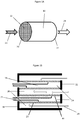
- the wall-flow filter has a front 20 and a rear 22, wherein the front 20 is designed to receive exhaust gas 21 prior to filtration and the rear 22 is designed to allow cleaned exhaust gas 29 to exit the filter 10.
- Wall-flow filter substrate has many square parallel channels 14 separated by thin porous walls 23 coated from the inlet side with a catalyst washcoat 44.
- the channels 14 extend in an axial direction from the front 20 of the substrate to the substrate's rear 22.
- the channels 14 are open only on one end.
- the opposite end of the channel is plugged.
- the plugged ends are arranged in alternating, checker-board pattern 12 between the front and rear so that exhaust gas 21 enters the channels 24 open to the front of the substrate, passes through the thin porous walls 23, enters the channels 26 open to the rear of the substrate, and then exits the substrate.
- the walls 23 have a porosity and pore size that are adequate for gas permeability, but are effective at trapping a major portion of the particulate matter, including soot, particularly when combined with a catalyst composition described herein. That is, as exhaust gas passes through the filter, particulate matter carried by the exhaust gas becomes trapped by the thin porous wall, thereby allowing particulate-free exhaust gas to exit the filter. The particulate matter accumulates on the filter until the filter is regenerated.
- the cross-sectional shape of the channels is not particularly limited and can be, for example, square, circular, oval, rectangular, triangular, hexagonal, and the like.
- Wall-flow filter substrates for diesel engines typically contain about 16 - 124 channels per square centimetre (100 - 800 cpsi (channels per square inch)), for example about 16 to about 62 channels per square centimetre (about 100 to about 400 cpsi), about 31 to about 47 channels per square centimetre (about 200 to about 300 cpsi), or about 78 to about 93 channels per square centimetre (about 500 to about 600 cpsi).
- the walls have an average wall thickness of about 0.1 to about 1.5 mm, for example about 0.15 to about 0.25 mm, about 0.25 to about 0.35 mm, or about 0.25 to about 0.50 mm.
- the porous walls 23 have an inlet side 30 and an outlet side 32 relative to the typical direction of exhaust gas flow 34 through the walls.
- the inlet side 30 has an inlet surface 40 that is exposed to the channels 24 open to the front of the substrate, and the outlet side 32 has an outlet surface 42 that is exposed to the channels 26 open to the rear of the substrate.
- the filter also has a center 50 that is equidistant from the outlet surface 42 and inlet surface 40.
- inlet side 30 with respect to the thin porous wall means the inlet surface 40 and the portion of the wall 23 from the inlet surface 40 to a depth of not more than about 10 percent, and more preferably about 10, about 5, or about 1 percent, of the distance between the inlet surface 40 and outlet surface 42.
- outlet side 32 with respect to the thin porous wall means outlet surface 42 and the portion of the wall 23 from the outlet surface 42 to a depth of not more than about 10 percent, and more preferably about 10, about 5, or about 1 percent, of the distance between the outlet surface 42 and inlet surfaces 40.
- the porous wall also has an interior portion that is between the inlet side 30 and the outlet side 32.
- the thickness of the interior is about 80 percent, and more preferably about 90 percent, of the total wall thickness.
- a catalyst coating is applied from the inlet side of the filter substrate and forms a catalyst coating gradient 44 within the inlet side, within the interior portion, and/or on the inlet surface, with the highest concentration of catalyst being towards the inlet surface.
- Figure 3 shows a cross-sectional diagram of a catalyst loaded filter according to an embodiment of the present invention.
- exhaust gas flows is a direction 21 from the inlet channels 24, through the catalyst coating 44, and into the outlet channels 26.
- the filter's useful range of porosity and mean pore size are not particularly limited but are correlated to, or are used to determine, the particle size of the catalyst coating.
- the filter substrate's porosity and mean pore size are determined based on a bare filter (e.g., without a catalyst coating).
- the porosity of the substrate is at least about 40%, more preferably at least about 50%, for example about 50 to about 80%, about 50 to about 70 percent, or about 55 to about 65 percent. Porosity may be measure by any suitable means, including mercury porosimetry.
- the mean pore size of the substrate is about 8 to about 40 ⁇ m, for example about 8 to about 12 ⁇ m, about 12 to about 20 ⁇ m, or about 15 to about 25 ⁇ m. In certain embodiments, at least about 50%, and more preferably at least about 75% of the pores are within these ranges, based on the total pore volume and/or total number of pores. Mean pore size can be determined by any acceptable means, including by mercury porosimetry.
- the filter substrate has a mean pore size of about 12 to about 15 ⁇ m and a porosity of about 50 to about 55%. In preferred embodiments, the filter substrate has a mean pore size of about 18 to about 20 ⁇ m and a porosity of about 55 to about 65%. These ranges correspond to a preferred catalyst composition d50 particle distribution of about 3.75 to about 5 microns.
- wall-flow substrates are high efficiency filters. Efficiency is determined by the weight percent of particulate matter having a specific size removed from the untreated exhaust gas upon passing through a wall-flow substrate. Therefore, efficiency is relative to soot and other similarly sized particles and to particulate concentrations typically found in conventional diesel exhaust gas. Particulates in diesel exhaust can range in size from 0.05 microns to 2.5 microns. Thus, the efficiency is based on this range.
- Wall flow filters for use with the present invention preferably have an efficiency of at least 70%, at least about 75%, at least about 80%, or at least about 90%. In certain embodiments, the efficiency will preferably be from about 75 to about 99%, about 75 to about 90%, about 80 to about 90%, or about 85 to about 95%.
- the pore interconnectivity measured as a percentage of the substrate's total void volume, is the degree to which pores, void, and/or channels, are joined to form continuous paths through a porous substrate, i.e., from the inlet face to the outlet face.
- pore interconnectivity is the sum of closed pore volume and the volume of pores that have a conduit to only one of the surfaces of the substrate.
- the porous substrate has a pore interconnectivity volume of at least about 30%, more preferably at least about 40%.
- the wall-flow filter substrate is an extruded catalytic body.
- Extruded catalytic bodies are distinguishable from non-catalytic substrates in that former involves a catalyst composition as part of the porous walls of the substrate, whereas the latter involves an inert substrate optionally having a catalyst coating applied to its porous walls.
- the thin porous walls of the filter substrate comprise one or more catalysts but do not contain a catalyst coating.
- the thin porous walls of the filter do not contain a catalyst except a catalyst coating.
- inert substrates are preferred due to their structural and performance properties and their versatility.
- an extruded solid body containing the source of catalyst involves blending the catalyst material, a binder, an optional organic viscosity-enhancing compound into a homogeneous paste which is then added to a binder/matrix component or a precursor thereof and optionally one or more of stabilized ceria and inorganic fibers.
- the blend is compacted in a mixing or kneading apparatus or an extruder.
- the mixtures have organic additives such as binders, pore formers, plasticizers, surfactants, lubricants, dispersants as processing aids to enhance wetting and therefore produce a uniform batch.
- the resulting plastic material is then molded, in particular using an extrusion press or an extruder including an extrusion die, and the resulting moldings are dried and calcined.
- the organic additives are "burnt out” during calcinations of the extruded solid body.
- the wall-flow filter substrates of the present invention contain a catalyst composition loaded from the inlet side of the filter, preferably only from the inlet, and preferably as a coating.
- a catalyst composition on the inlet side of the filter means that at least 90 weight percent of the catalyst composition is on the inlet side and interior portion of the filter. In certain embodiments, at least about 95 weight percent of the catalyst composition is on the outlet side and interior portion of the filter. Preferably, essentially all of the catalyst composition is on the outlet side and interior portion of the filter.
- the catalyst composition forms a concentration gradient between the inlet surface of the filter and the outlet side of the filter, wherein the concentration is greatest towards the inlet surface.
- at least 50, 75, 90, 95, or 99 weight percent of the catalyst composition is between the inlet surface and center of the filter wall.
- the wall-flow filter substrate preferably has an outlet side that is substantially free of catalyst coatings.
- substantially free with respect to a particular zone on the filter means that the zone does not contain a catalyst coating, or if a catalyst coating is present, the loading is low enough so as not to increase the backpressure across the filter by more than 5% at a median soot load produced during typical operating conditions relative to a bare filter or a filter without such coating.
- a filter having an inlet side substantially free of catalyst may contain an inlet side coating of less than 0.006 g/cm 3 (0.1 g/in 3 ), more preferably less than 0.03 g/cm 3 (0.05 g/in 3 ), and even more preferably less than 0.0006 g/cm 3 (0.01 g/in 3 ).
- the inlet side of the filter is substantially free of a catalyst coating
- the total amount of the catalyst coating on the inlet side is less than about 5 weight percent, and more preferably less than about 1 weight percent, and even more preferably less than 0.1 weight percent of the total catalyst coating on the filter, and is preferably less than about 5 weight percent, and more preferably less than about 1 weight percent, and even more preferably less than 0.1 weight percent of the catalyst coating on the outlet side of the filter.
- the catalyst coating referred to herein does not include catalyst material that forms part of the substrate (e.g., an extruded catalytic body).
- the wall-flow filter substrate has an interior that is substantially free of catalyst coatings.
- a filter having an interior substantially free of catalyst may contain an interior coating of less than 0.01 g/cm 3 (0.2 g/in 3 ), and more preferably less than 0.03 g/cm 3 (0.05 g/in 3 ).
- the total amount of the catalyst coating is less than about 5 weight percent, more preferably less than about 1 weight percent, and even more preferably less than 0.1 weight percent of the total catalyst coating on the filter and is preferably less than about 5 weight percent, preferably less than about 1 weight percent, and even more preferably less than 0.1 weight percent of the total catalyst coating on the outlet side of the filter.
- the catalyst coating referred to herein does not include catalyst material that forms part of the substrate (e.g., an extruded catalytic body).
- the catalyst coating referred to herein does not include non-catalytic membranes or other non-catalytic thin layer coatings that may be applied to the filter wall as a processing aide (e.g., to improve adhesion of the catalytic coating to the filter wall), a passivation layer, or to reinforce, strengthen, or stabilize the filter wall.
- a non-catalytic layer if present, has a thickness and/or loading that does not significantly affect the backpressure of the filter, for example, does not increase or decrease the backpressure by more than about 5% compared to a similar filter substrate without the non-catalytic coating.
- the filter substrate contains a non-catalytic layer in addition to the catalyst coating (e.g., a catalyst coating applied to a passivated substrate).
- the filter substrate contains a catalyst coating, but is free from non-catalytic coatings (e.g., a catalyst coating applied to an unpassivated substrate).
- the catalyst composition loaded from the inlet side of the filter is arranged as a single layer or zone.
- the catalyst composition on the inlet side of the filter is arranged as two or more layers or zones wherein each layer or zone comprises the same or different catalyst compositions.
- the d50 particle size distribution is based on the catalyst composition as whole.
- a catalyst coating comprises a consecutive first catalytic layer and a second catalytic layer on the outlet side of the substrate.
- consecutive with respect to the layers means that each layer is contact with its adjacent layer(s) and that the layers as a whole are arranged one on top of another on the substrate.
- first layer and second layer are used to describe the relative positions of catalyst layers in the catalyst article with respect to the normal direction of exhaust gas flow through, past, and/or over the catalyst article. Under normal exhaust gas flow conditions, exhaust gas contacts the first layer prior to contacting the second layer.
- the first layer is applied to an inert substrate as a bottom layer and the second layer is top layer that is applied over the second layer.
- the catalyst composition preferably has a small particle size relative to the mean pore size of the filter.
- the catalyst composition has a d 50 particle size distribution that is less than the mean pore size divided by 4.9.
- d 50 particle size distribution means the median diameter or the medium value of the particle size distribution. It is the value of the particle diameter at 50% in the cumulative distribution.
- particle size distribution means the number of particles that fall into a size range as a percentage of the total number of all sizes in a sample.
- the particle size distribution of the catalyst composition is measured based on the particle size of the catalytically active component. In other embodiments, the particle size of the catalyst composition is measured based on the catalyst composition as a whole. In certain embodiments, the catalyst composition is part of a washcoat and in other embodiments, the catalyst composition is a washcoat (i.e., includes other non-catalytic components) or catalyst coating. That is, a measurement of the particle size distribution is not limited to the catalyst particles in the coating, but instead includes all particles in the coating, such as binders, rheology modifiers, etc. In certain embodiments, the particles in a distribution contain at least 50%, and more preferably at least 75%, (by number and/or by weight) of catalyst particles.
- the catalyst coating has a d 50 particle size distribution of about 0.1 to about 5 ⁇ m, preferably about 0.5 to about 3 ⁇ m, such as about 1.0 to about 2.0 ⁇ m.
- the filter substrate has a relatively large mean pore size (e.g., greater than about 10 ⁇ m) and the catalyst coating has a relatively small d 50 particle size distribution (e.g., greater than about 3 ⁇ m).
- the filter has a mean pore size of about 10 to about 25 ⁇ m, such as about 12 to about 15 ⁇ m or about 17 to about 21 ⁇ m, a porous of about 55 to about 70%, and catalyst coating has a d 50 particle size distribution of about 0.5 to about 2.0 ⁇ m.
- Certain catalyst coatings for the present invention have a d 10 particle size distribution of about 0.1 to about 1.0, for example about 0.2, 0.5, or 0.7. Certain catalyst coating for the present invention have a d 90 particle size distribution of less than about 8 ⁇ m, preferably less than about 5 ⁇ m, for example about 4 ⁇ m, 3 ⁇ m, or 2 ⁇ m. As used herein, “d 10 particle size distribution” means that 90 percent of the particles in a sample are greater than the stated value. As used herein, “d 90 particle size distribution” means that less than 90 percent of the particles in a sample are less than the stated value.
- the loading concentration of the catalyst coating is not particularly limited, provided that the catalyst composition is present in an amount effective to catalyze the targeted exhaust gas component.
- the catalyst composition is present in a concentration of at least about 0.006 g/cm 3 (about 0.1 g/in 3 ), and preferably at least about 0.018 g/cm 3 (about 0.3 g/in 3 ).
- the catalyst composition has a loading of about 0.03 to about 0.24 g/cm 3 (about 0.5 to about 4 g/in 3 ), more preferably about 0.046 to about 0.12 g/cm 3 (about 0.75 to about 2 g/in 3 ), and even more preferably about 0.06 to about 0.09 g/cm 3 (about 1.0 to about 1.5 g/in 3 ) or about 0.09 to about 0.15 g/cm 3 (about 1.5 to about 2.5 g/in 3 ).
- the loading concentration is preferable measured based on the active catalytic component, but may be based on entire catalyst coating.
- Preferred catalyst compositions include those useful for reducing the concentrations of NO x , NH 3 , SO x , CO and/or hydrocarbons in the exhaust gas.
- Other useful catalyst include NO x absorbers and NO x traps.
- the catalyst is a heterogeneous catalyst that comprises a metal on and/or in a high surface area material, such as a molecular sieve or refractory metal oxide. The metal is preferably impregnated, doped, or supported by the high surface area material.
- Preferred metals are transition metal and/or a platinum group metal.
- useful metals include copper, nickel, zinc, iron, tin, tungsten, molybdenum, cobalt, bismuth, titanium, zirconium, antimony, manganese, chromium, vanadium, niobium, ruthenium, rhodium, palladium, gold, silver, indium, platinum, iridium, rhenium, and mixtures thereof, with copper, manganese, and iron being particularly preferred.
- the catalysts may also include other stabilizing metals such as calcium, magnesium, potassium, and/or rare earth metals such as cerium and lanthanum. These materials are particularly well suited for use as an SCR catalyst, AMOX catalyst, NO x traps, NO x absorbers, oxidation catalysts, and the like.
- the high surface area material is in the form of particles, crystals, or agglomeration of particles or crystals, wherein the particles, crystals, or agglomeration have a d 50 particle size distribution as described herein.
- high surface area materials include metal oxides such as alumina, titania, zirconia, ceria, silica, oxides of tungsten, oxides of molybdenum, and mixtures of these. These materials, when used as supports, are particularly useful for PGM-based catalyst and vanadium-based catalysts.
- a non-zeolite based SCR catalyst can include V 2 O 5 supported by TiO 2 /WO 3 .
- an oxidation catalyst, AMOX catalyst, NO x absorber catalyst, or NO x trap can include a PGM metal, such as Pt, Pd, Rh, and combinations of these supported by alumina, titania, and the like.
- suitable high surface area material include molecular sieves such as aluminosilicates (zeolites), silicoaluminophosphates (SAPOs), ferrosilicates, etc.
- zeolites aluminosilicates
- SAPOs silicoaluminophosphates
- ferrosilicates etc.
- preferred molecular sieves include zeolites and SAPOs having a small pore framework (i.e., having a maximum ring size of 8).
- small pore molecular sieves include those having a Framework Type Code selected from the group consisting of: ACO, AEI, AEN, AFN, AFT, AFX, ANA, APC, APD, ATT, CDO, CHA, DDR, DFT, EAB, EDI, EPI, ERI, GIS, GOO, IHW, ITE, ITW, LEV, KFI, MER, MON, NSI, OWE, PAU, PHI, RHO, RTH, SAT, SAV, SIV, THO, TSC, UEI, UFI, VNI, YUG and ZON.
- a Framework Type Code selected from the group consisting of: ACO, AEI, AEN, AFN, AFT, AFX, ANA, APC, APD, ATT, CDO, CHA, DDR, DFT, EAB, EDI, EPI, ERI, GIS, GOO, IHW, ITE, ITW, LEV, KFI
- zeolites having a specific Framework Type Code include the all isotypic framework materials defined by that Framework Type Code.
- Preferred zeolites have a mole silica to alumina ratio (SAR) of less than about 30, more preferably about 5 to about 30, for example about 10 to about 25, from about 14 to about 20, from about 20 to about 30, or from about 15 to about 17.
- SAR mole silica to alumina ratio
- the silica-to-alumina ratio of zeolites may be determined by conventional analysis. This ratio is meant to represent, as closely as possible, the ratio in the rigid atomic framework of the zeolite crystal and to exclude silicon or aluminum in the binder or in cationic or other form within the channels.
- silica-to-alumina ratios are expressed in terms of the SAR of the zeolite per se, i.e., prior to the combination of the zeolite with the other catalyst components.
- the small pore molecular sieve comprises, consists essentially of, or consists of a disordered framework selected from the group consisting of ABC-6, AEI/CHA, AEI/SAV, AEN/UEI, AFS/BPH, BEC/ISV, beta, fuajasite, ITE/RTH, KFI/SAV, lovdarite, montesommaite, MTT/TON, pentasils, SBS/SBT, SSF/STF, SSZ-33, and ZSM-48.
- a disordered framework selected from the group consisting of ABC-6, AEI/CHA, AEI/SAV, AEN/UEI, AFS/BPH, BEC/ISV, beta, fuajasite, ITE/RTH, KFI/SAV, lovdarite, montesommaite, MTT/TON, pentasils, SBS/SBT, SSF/STF, SSZ-33, and ZSM-48.
- one or more of the small pore molecular sieves may comprise a CHA Framework Type Code selected from SAPO-34, AIPO-34, SAPO-47, ZYT-6, CAL-1, SAPO-40, SSZ-62 or SSZ-13 and/or an AEI Framework Type Code of selected from AIPO-18, SAPO-18, SIZ-8, or SSZ-39.
- the mixed phase composition is an AEI/CHA-mixed phase composition.
- the ratio of each framework type in the molecular sieve is not particularly limited.
- the ratio of AEI/CHA may range from about 5/95 to about 95/5, preferably about 60/40 to 40/60.
- the ratio of AEI/CHA may range from about 5/95 to about 40/60.
- catalysts useful in SCR applications include copper or iron on a zeolite having a small pore framework, such as CHA, AEI, and the like.
- the catalyst metal is present on and/or within a molecular sieve material at a concentration of about 0.1 to about 10 weight percent (wt%) based on the total weight of the molecular sieve, for example from about 0.5 wt% to about 5 wt%, from about 0.5 to about 1 wt%, from about 1 to about 5 wt%, about 2 wt% to about 4 wt%, and about 2 wt% to about 3 wt %.
- the metal may be incorporated into the molecular sieves for use in the present invention using techniques well known in the art, including liquid-phase exchange or solid-ion exchange or by an incipient wetness process.
- Other molecular sieve frameworks useful as SCR catalysts in the present invention include BEA, MOR, and MFI, particularly when included with one or more small-pore molecular sieves.
- Catalyst composition can be in the form of a washcoat comprising the catalyst, preferably a washcoat that is suitable for coating a diesel particulate filter substrate.
- the washcoat can include catalytically inactive components such as binders, rheology modifiers, pore forming agents, dispersants, wetting agents, and the like.
- a "catalytically active" component of the washcoat is one that directly participates as a molecular component in the desired catalytic process, such as the catalytic reduction of NO x and/or oxidization of NH 3 or other nitrogenous-based SCR reductants.
- a “catalytically inactive” is a component in the washcoat that does not directly participate as a molecular component in the desired catalytic process.
- Preferred inactive components include binders, such as alumina, silica, (non-zeolite) silica-alumina, naturally occurring clays, TiO 2 , ZrO 2 , and SnO 2 .
- binders such as alumina, silica, (non-zeolite) silica-alumina, naturally occurring clays, TiO 2 , ZrO 2 , and SnO 2 .
- the catalytically inactive form of the material is typically distinguishable based on a physical property, such as particle size.
- the catalyst coating may be deposited on the outlet side of the filter substrate by first forming a slurry of the functional catalyst and contacting the filter substrate with the slurry to allow the slurry to coat the outlet surface and/or infiltrate the filter to a desired depth which, preferably, is no greater than the depth of the outlet side of the filter. More specifically, the slurry is dosed onto the rear of the filter or the rear of the filter is dipped into the slurry so that the slurry enters the outlet channels of the filter. The slurry then forms a membrane-type coating on the outlet surface and/or partially permeates the open porous structure of the filter walls thereby forming a catalyst coating on the outlet side of the filter.
- a vacuum system may be attached to the front of the particulate filter to draw the catalyst washcoat partially through the channel walls.
- the excess slurry is removed from the particulate filter by draining, air knife, or other technique.
- a compressed fluid such as compressed air, may be injected into the filter channels to assist in removing the remaining slurry. Thereafter, the particulate filter is dried.
- the catalyst is exposed to temperatures of up to 950 °C. In certain embodiments, the catalyst is operational at a temperature of about 150 °C to about 850 °C. In a particular embodiment, the temperature range is from 175 to 550 °C. In another embodiment, the temperature range is from 175 to 400 °C.
- a method for removing particulate matter, including soot, from an exhaust gas and catalyzing a reaction to effect the concentration of at least one component in the exhaust gas Upon entering the inlet channels, the exhaust gas contacts and passes through the thin porous walls of the filter which removes soot from the exhaust gas, preferably prior to the exhaust gas contacting the catalyst coating.
- particulate matter e.g., soot
- the permeability of the channel walls decreases thus causing an increase in backpressure.
- the permeability of the particulate filter can be restored by regenerating the filter which typically involves burning the deposited soot. Regeneration may occur actively or passively.
- the exhaust gas upstream of the filter is periodically increased, for example, by dosing hydrocarbon into the exhaust gas stream and converting the hydrocarbon into heat over an oxidation catalyst upstream of the filter.
- the increase in heat facilitates soot burn to remove soot from the filter and thereby reducing backpressure.
- the soot deposited on the channel walls reacts with NO 2 present in the exhaust gas stream causing the soot to combust and yield NO.
- the reaction between the soot and NO 2 present in the exhaust gas stream balances with the soot loading rate when the soot load reaches a balance point below a predetermined operation limit of the particulate filter.
- the catalyst article reduces the concentration of NO x in the exhaust gas. In other embodiments, the catalyst article increases the concentration of NO, NO 2 or modifies the ratio of NO:NO 2 . In certain embodiments, the catalyst reduces the concentration of NH 3 in the exhaust gas.
- the catalyst compositions described herein can promote a reaction involving a reductant, preferably ammonia, and nitrogen oxides to selectively form elemental nitrogen (N 2 ) and water (H 2 O) vis-à-vis the competing reaction of oxygen and ammonia.
- a reductant preferably ammonia
- nitrogen oxides to selectively form elemental nitrogen (N 2 ) and water (H 2 O) vis-à-vis the competing reaction of oxygen and ammonia.
- the catalyst can be formulated to favor the reduction of nitrogen oxides with ammonia (i.e., an SCR catalyst).
- the catalyst can be formulated to favor the oxidation of ammonia with oxygen (i.e., an ammonia oxidation (AMOX) catalyst).
- Sources of ammonia include ammonia reductant that is not consumed by the SCR process (i.e., ammonia slip).
- an SCR catalyst and an AMOX catalyst are used in series, wherein both catalyst comprise the metal containing zeolite described herein, and wherein the SCR catalyst is upstream of the AMOX catalyst.
- the AMOX catalyst is disposed as a top layer on an oxidative under-layer, wherein the under-layer comprises a platinum group metal (PGM) catalyst (e.g., Pt or Pt/Pd) or a non-PGM catalyst on a high surface area support such as alumina.
- PGM platinum group metal
- the AMOX catalyst can be applied to the substrate as a washcoat, preferably to achieve a loading of about 0.018 to 0.14 g/cm 3 (about 0.3 to 2.3 g/in 3 ).
- the reductant (also known as a reducing agent) for SCR processes broadly means any compound that promotes the reduction of NO x in an exhaust gas.
- reductants useful in the present invention include ammonia, hydrazine or any suitable ammonia precursor, such as urea ((NH 2 ) 2 CO), ammonium carbonate, ammonium carbamate, ammonium hydrogen carbonate or ammonium formate, and hydrocarbons such as diesel fuel, and the like.
- Particularly preferred reductant are nitrogen based, with ammonia being particularly preferred.
- the reductant can be a hydrocarbon, such as methane, diesel fuel, or the like.
- a nitrogenous reducing agent or precursor thereof is introduced into the exhaust gas flow stream, preferably upstream of an SCR catalyst and downstream of a diesel oxidation catalyst.
- the introduction of this reducing agent can be accomplished by an injector, spray nozzle, or similar device.
- all or at least a portion of the nitrogen-based reductant, particularly NH 3 can be supplied by a NO X adsorber catalyst (NAC), a lean NO X trap (LNT), or a NO x storage/reduction catalyst (NSRC), disposed upstream of the SCR catalyst, e.g., a SCR catalyst of the present invention disposed on a wall-flow filter.
- NAC NO X adsorber catalyst
- LNT lean NO X trap
- NSRC NO x storage/reduction catalyst
- NAC components useful in the present invention include a catalyst combination of a basic material (such as alkali metal, alkaline earth metal or a rare earth metal, including oxides of alkali metals, oxides of alkaline earth metals, and combinations thereof), and a precious metal (such as platinum), and optionally a reduction catalyst component, such as rhodium.
- a basic material such as alkali metal, alkaline earth metal or a rare earth metal, including oxides of alkali metals, oxides of alkaline earth metals, and combinations thereof
- a precious metal such as platinum
- a reduction catalyst component such as rhodium.
- Specific types of basic material useful in the NAC include cesium oxide, potassium oxide, magnesium oxide, sodium oxide, calcium oxide, strontium oxide, barium oxide, and combinations thereof.
- the precious metal is preferably present at about 0.37 to about 7.41 g/L (about 10 to about 200 g/ft 3 ), such as 0.74 to 2.22 g/L (20 to 60 g
- NH 3 may be generated over a NO x adsorber catalyst.
- the SCR catalyst downstream of the NO x adsorber catalyst may improve the overall system NO x reduction efficiency.
- the SCR catalyst is capable of storing the released NH 3 from the NAC catalyst during rich regeneration events and utilizes the stored NH 3 to selectively reduce some or all of the NO x that slips through the NAC catalyst during the normal lean operation conditions.
- Methods of the present invention can comprise one or more of the following steps: (a) accumulating and/or burning soot that is in contact with the inlet of a catalytic filter; (b) introducing a nitrogenous reducing agent into the exhaust gas stream prior to contacting the catalytic filter, preferably with no intervening catalytic steps involving the treatment of NO x and the reductant; (c) generating NH 3 over a NO x adsorber catalyst, and preferably using such NH 3 as a reductant in a downstream SCR reaction; (d) contacting the exhaust gas stream with a DOC to oxidize hydrocarbon based soluble organic fraction (SOF) and/or carbon monoxide into CO 2 , and/or oxidize NO into NO 2 , which in turn, may be used to oxidize particulate matter in particulate filter; and/or reduce the particulate matter (PM) in the exhaust gas; (e) contacting the exhaust gas with one or more flow-through SCR catalyst device(s) in the presence of
- Methods of the present invention can be performed on an exhaust gas derived from a combustion process, such as from an internal combustion engine (whether mobile or stationary), a gas turbine and coal or oil fired power plants.
- the method may also be used to treat gas from industrial processes such as refining, from refinery heaters and boilers, furnaces, the chemical processing industry, coke ovens, municipal waste plants and incinerators, etc.
- the method is used for treating exhaust gas from a vehicular lean burn internal combustion engine, such as a diesel engine, a lean-burn gasoline engine or an engine powered by liquid petroleum gas or natural gas.
- the invention provides an exhaust system for a vehicular lean burn internal combustion engine, which system comprising a conduit for carrying a flowing exhaust gas, a source of nitrogenous reductant, and a catalyst blend described herein.
- the system can include a controller for the metering the nitrogenous reductant into the flowing exhaust gas only when it is determined that the catalyst blend is capable of catalyzing NO x reduction at or above a desired efficiency, such as at above 100 °C, above 150 °C or above 175 °C.
- the metering of the nitrogenous reductant can be arranged such that 60% to 200% of theoretical ammonia is present in exhaust gas entering the SCR catalyst calculated at 1:1 NH 3 /NO and 4:3 NH 3 /NO 2 .
- the control means can comprise a pre-programmed processor such as an electronic control unit (ECU).
- a catalyst for oxidizing nitrogen monoxide in the exhaust gas to nitrogen dioxide can be located upstream of a point of metering the nitrogenous reductant into the exhaust gas.
- the diesel oxidation catalyst (DOC) is adapted to yield a gas stream entering the SCR zeolite catalyst having a ratio of NO to NO 2 of from about 4:1 to about 1:3 by volume, e.g. at an exhaust gas temperature at oxidation catalyst inlet of 250 °C to 450 °C.
- the NO to NO 2 is maintained at a ratio of about 1:2 to about 1:5 by volume.
- the diesel oxidation catalyst can include at least one platinum group metal (or some combination of these), such as platinum, palladium, or rhodium, coated on a flow-through monolith substrate.
- the at least one platinum group metal is platinum, palladium, or a combination of both platinum and palladium.
- the platinum group metal can be supported on a high surface area washcoat component such as alumina, a zeolite such as an aluminosilicate zeolite, silica, non-zeolite silica alumina, ceria, zirconia, titania or a mixed or composite oxide containing both ceria and zirconia.
- the zeolite catalyst for use in the present invention is coated on a filter located downstream of the oxidation catalyst.
- the filter includes the zeolite catalyst for use in the present invention
- the point of metering the nitrogenous reductant is preferably located between the oxidation catalyst and the filter.
- a vehicular lean-burn engine comprising an exhaust system according to the present invention.
- the vehicular lean burn internal combustion engine can be a diesel engine, a lean-burn gasoline engine or an engine powered by liquid petroleum gas or natural gas.
- the term "consists essentially of" with respect to a catalytic composition means that the composition contains the named catalytic components but does not contain additional components that materially affect the basic and novel characteristics of the claimed invention. That is, the catalytic composition does not include additional components that would otherwise serve as a catalyst for the intended reaction or serve to enhance the basic catalytic nature of the claimed catalyst.
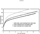
- Example 1 Diesel Particulate Filter with Catalyst Coated Inlet
- a catalytic washcoating having a copper impregnated molecular sieve having a CHA framework was washcoated from the inlet side of a honeycomb-type wall-flow filter constructed primarily of cordierite and having 300 cpsi and a wall thickness of 12 mils (0.3 mm) and then dried.
- Scanning Electron Microscope (SEM) imaging confirmed that the catalyst coating remained on the inlet side and interior portion of the filter wall. The inlet side of the filter wall remained free of catalyst coatings.
- the washcoat was applied in an amount sufficient to form a catalyst loading of about 0.06 g/cm 3 (about 1 g/in 3 ).
- the catalyst loading had a d 50 particle size distribution of about 1.5 ⁇ m.
- Comparative Examples A - B Diesel Particulate Filters with Catalyst Coated Outlet and on both Inlet and Outlet
- Example 1 and Comparative Examples A and B are shown in Figure 4 .
- the soot loaded backpressure of Comparative Examples A and B is substantially higher than Example 1.
Landscapes
- Engineering & Computer Science (AREA)
- Chemical & Material Sciences (AREA)
- Combustion & Propulsion (AREA)
- Mechanical Engineering (AREA)
- General Engineering & Computer Science (AREA)
- Chemical Kinetics & Catalysis (AREA)
- Environmental & Geological Engineering (AREA)
- Biomedical Technology (AREA)
- Health & Medical Sciences (AREA)
- Analytical Chemistry (AREA)
- General Chemical & Material Sciences (AREA)
- Oil, Petroleum & Natural Gas (AREA)
- Exhaust Gas After Treatment (AREA)
- Catalysts (AREA)
- Processes For Solid Components From Exhaust (AREA)
- Exhaust Gas Treatment By Means Of Catalyst (AREA)
- Filtering Materials (AREA)
- Filtering Of Dispersed Particles In Gases (AREA)
Claims (15)
- Filtre à particules pour moteur diesel comprenant :a. un substrat de filtre à paroi filtrante (10) ayant une taille moyenne de pore, un côté entrée (30), un côté sortie (32), et un intérieur poreux (23) entre les côtés entrée et sortie ; etb. une composition de catalyseur (44) enduite depuis le côté entrée du substrat, la composition de catalyseur ayant une distribution d50 des tailles de particule,où ladite distribution d50 des tailles de particule est inférieure à la taille moyenne de pore divisée par 4,9, et le côté sortie étant sensiblement exempt d'enduction de catalyseur.
- Filtre à particules pour moteur diesel selon la revendication 1, dans lequel la taille moyenne de pore est d'au moins environ 10 µm, préférablement d'au moins environ 15 µm.
- Filtre à particules pour moteur diesel selon la revendication 1, dans lequel le substrat de filtre à paroi filtrante comprend en outre une porosité d'au moins environ 45 pour cent, préférablement d'au moins environ 55 pour cent, plus préférablement d'au moins environ 65 pour cent.
- Filtre à particules pour moteur diesel selon la revendication 1, dans lequel ladite distribution d50 des tailles de particule n'est pas supérieure à environ 2,5 microns, préférablement non supérieure à environ 2 microns.
- Filtre à particules pour moteur diesel selon la revendication 1, dans lequel ladite distribution d50 des tailles de particule est d'environ 1 à environ 2 microns.
- Filtre à particules pour moteur diesel selon la revendication 1, dans lequel l'intérieur poreux est sensiblement exempt d'enduction de catalyseur.
- Filtre à particules pour moteur diesel selon la revendication 1, dans lequel la composition de catalyseur est présente en une quantité d'environ 0,003 à 0,18 g/cm3 (0,5 à 3,0 g/pouce3), préférablement d'environ 0,05 à 0,11 g/cm3 (0,9 à 1,8 g/pouce3).
- Filtre à particules pour moteur diesel selon la revendication 1, dans lequel la composition de catalyseur est présente sous la forme d'une couche unique.
- Filtre à particules pour moteur diesel selon la revendication 1, comprenant en outre des couches de catalyseurs additionnelles enduites depuis le côté entrée du filtre.
- Filtre à particules pour moteur diesel selon la revendication 1, dans lequel la couche d'enduction de catalyseur comprend un catalyseur de réduction sélective.
- Filtre à particules pour moteur diesel selon la revendication 10, dans lequel ledit catalyseur de réduction sélective comprend du Cu ou Fe sur et/ou à l'intérieur d'un tamis moléculaire à petits pores.
- Filtre à particules pour moteur diesel selon la revendication 1, dans lequel la couche d'enduction de catalyseur comprend un catalyseur de réduction de l'ammoniac résiduel.
- Système de traitement d'un gaz d'échappement à mélange pauvre comprenant :a. un filtre à particules pour moteur diesel selon la revendication 1 ; etb. au moins un constituant de système d'échappement en communication fluidique avec le filtre à particules pour moteur diesel, le constituant de système d'échappement étant sélectionné dans le groupe constitué d'une source de NO2 disposée en amont du filtre à particules pour moteur diesel, une source d'agent réducteur disposée en amont du filtre à particules pour moteur diesel, un catalyseur d'AMOX, un piège à NOx, un catalyseur absorbant les NOx, un catalyseur d'oxydation diesel, et un catalyseur SCR.
- Procédé de réduction des particules de suie dans un gaz d'échappement à mélange pauvre comprenant :a. la mise en contact d'un écoulement de gaz d'échappement transportant des particules de suie et éventuellement contenant des NOx, avec un filtre à particules pour moteur diesel selon la revendication 1 ;b. le piégeage d'au moins une partie des particules de suie sur et/ou dans le filtre à particules pour moteur diesel tout en permettant au gaz d'échappement de passer à travers le filtre à particules pour moteur diesel ; etc. la combustion périodique et/ou de manière continue des particules de suie piégées pour régénérer le filtre.
- Procédé selon la revendication 19 comprenant en outre l'étape de :a. mise en contact du gaz d'échappement avec un catalyseur SCR enduit depuis le côté entrée du filtre pour réduire la concentration des NOx dans le gaz d'échappement.
Applications Claiming Priority (2)
| Application Number | Priority Date | Filing Date | Title |
|---|---|---|---|
| US201361829286P | 2013-05-31 | 2013-05-31 | |
| PCT/US2014/040290 WO2014194229A1 (fr) | 2013-05-31 | 2014-05-30 | Filtre catalysé permettant le traitement de gaz d'échappement |
Publications (2)
| Publication Number | Publication Date |
|---|---|
| EP3004579A1 EP3004579A1 (fr) | 2016-04-13 |
| EP3004579B1 true EP3004579B1 (fr) | 2018-03-07 |
Family
ID=51059620
Family Applications (1)
| Application Number | Title | Priority Date | Filing Date |
|---|---|---|---|
| EP14734670.4A Active EP3004579B1 (fr) | 2013-05-31 | 2014-05-30 | Filtre catalysé pour traiter les gaz d'échappement |
Country Status (10)
| Country | Link |
|---|---|
| US (1) | US9687786B2 (fr) |
| EP (1) | EP3004579B1 (fr) |
| JP (2) | JP2016530070A (fr) |
| KR (1) | KR20160014713A (fr) |
| CN (2) | CN105247179B (fr) |
| BR (1) | BR112015029656A2 (fr) |
| DE (1) | DE102014107669A1 (fr) |
| GB (1) | GB2517035C (fr) |
| RU (1) | RU2629762C2 (fr) |
| WO (1) | WO2014194229A1 (fr) |
Families Citing this family (20)
| Publication number | Priority date | Publication date | Assignee | Title |
|---|---|---|---|---|
| KR20160056174A (ko) * | 2014-11-11 | 2016-05-19 | 현대자동차주식회사 | 디젤매연필터의 촉매 코팅방법 |
| CN107427777A (zh) * | 2015-03-25 | 2017-12-01 | 庄信万丰股份有限公司 | 包含贵金属和具有OFF骨架类型的分子筛的被动NOx吸附剂 |
| JP6219871B2 (ja) | 2015-03-27 | 2017-10-25 | トヨタ自動車株式会社 | 排ガス浄化用触媒 |
| JP6243371B2 (ja) | 2015-03-27 | 2017-12-06 | トヨタ自動車株式会社 | 排ガス浄化用触媒 |
| JP6130424B2 (ja) | 2015-03-27 | 2017-05-17 | トヨタ自動車株式会社 | 排ガス浄化用触媒 |
| JP6130423B2 (ja) * | 2015-03-27 | 2017-05-17 | トヨタ自動車株式会社 | 排ガス浄化用触媒 |
| US10215073B2 (en) * | 2015-05-19 | 2019-02-26 | Basf Corporation | Catalyzed soot filter for use in passive selective catalytic reduction |
| US10137412B2 (en) * | 2016-01-07 | 2018-11-27 | Johnson Matthey Japan G.K. | Filter |
| JP6426650B2 (ja) * | 2016-04-12 | 2018-11-21 | トヨタ自動車株式会社 | 排ガス浄化用触媒 |
| US10744496B2 (en) | 2016-07-22 | 2020-08-18 | Johnson Matthey Public Limited Company | Catalyst binders for filter substrates |
| GB201622179D0 (en) * | 2016-12-23 | 2017-02-08 | Johnson Matthey Plc | Gasoline particulate filter |
| DE102017103341A1 (de) * | 2017-02-17 | 2018-08-23 | Umicore Ag & Co. Kg | Russpartikelfilter mit speicherzellen für katalysator |
| DE102018107545A1 (de) * | 2017-03-30 | 2018-10-04 | Johnson Matthey Public Limited Company | Asc/dec mit rückwärtig konzentrierter exothermenerzeugung |
| JP2020533511A (ja) * | 2017-08-10 | 2020-11-19 | コーニング インコーポレイテッド | 微粒子フィルタ上のscr触媒膜 |
| DE102017215494A1 (de) * | 2017-09-04 | 2019-03-07 | Dr Pley Engineering & Consulting (Bucharest) Srl | Katalysatoren zum entfernen von schadgasen aus dem abgas von dieselmotoren |
| EP3787772A2 (fr) * | 2018-05-04 | 2021-03-10 | Corning Incorporated | Corps en nid d'abeilles en céramique à sortie revêtue et leurs procédés de fabrication |
| CN111699039A (zh) * | 2018-05-17 | 2020-09-22 | N.E.化学株式会社 | 废气净化催化剂 |
| US20220016601A1 (en) * | 2018-11-21 | 2022-01-20 | Cataler Corporation | Exhaust-gas purification apparatus and method for manufacturing same |
| CN110201666B (zh) * | 2019-06-20 | 2022-01-25 | 中自环保科技股份有限公司 | 一种汽油机颗粒捕集催化剂及其制备方法 |
| EP3932542A1 (fr) * | 2020-07-03 | 2022-01-05 | BASF Corporation | Catalyseur pour la combustion de particules dans des systèmes de traitement des émissions d'essence |
Family Cites Families (45)
| Publication number | Priority date | Publication date | Assignee | Title |
|---|---|---|---|---|
| WO2002026379A1 (fr) | 2000-09-29 | 2002-04-04 | Omg Ag & Co. Kg | Filtre catalytique de particules de suie et utilisation de celui-ci afin de traiter des gaz d'echappement pauvres |
| US6946013B2 (en) * | 2002-10-28 | 2005-09-20 | Geo2 Technologies, Inc. | Ceramic exhaust filter |
| US7229597B2 (en) * | 2003-08-05 | 2007-06-12 | Basfd Catalysts Llc | Catalyzed SCR filter and emission treatment system |
| US7490464B2 (en) * | 2003-11-04 | 2009-02-17 | Basf Catalysts Llc | Emissions treatment system with NSR and SCR catalysts |
| GB0405015D0 (en) * | 2004-03-05 | 2004-04-07 | Johnson Matthey Plc | Method of loading a monolith with catalyst and/or washcoat |
| JP2006007117A (ja) | 2004-06-25 | 2006-01-12 | Ne Chemcat Corp | 排気ガス浄化構造体および該構造体を用いた排気ガス浄化方法 |
| US7722829B2 (en) * | 2004-09-14 | 2010-05-25 | Basf Catalysts Llc | Pressure-balanced, catalyzed soot filter |
| DE102005005663A1 (de) * | 2005-02-08 | 2006-08-17 | Daimlerchrysler Ag | Abgasnachbehandlungseinrichtung mit Partikelfilter |
| JP4971166B2 (ja) * | 2005-08-31 | 2012-07-11 | 日本碍子株式会社 | ハニカム触媒体、ハニカム触媒体製造用のプレコート担体及びハニカム触媒体の製造方法 |
| US7211232B1 (en) * | 2005-11-07 | 2007-05-01 | Geo2 Technologies, Inc. | Refractory exhaust filtering method and apparatus |
| US8119075B2 (en) * | 2005-11-10 | 2012-02-21 | Basf Corporation | Diesel particulate filters having ultra-thin catalyzed oxidation coatings |
| US7485170B2 (en) * | 2005-11-30 | 2009-02-03 | Corning Incorporated | Narrow pore size distribution cordierite ceramic honeycomb articles and methods for manufacturing same |
| JP2009519814A (ja) * | 2005-12-16 | 2009-05-21 | コーニング インコーポレイテッド | 圧力降下の低い被覆ディーゼル排ガスフィルタ |
| JP5073303B2 (ja) * | 2006-03-24 | 2012-11-14 | 日本碍子株式会社 | 触媒コンバータ及び触媒コンバータの製造方法 |
| GB0618482D0 (en) * | 2006-09-20 | 2006-11-01 | Johnson Matthey Plc | Washcoated particulate filter substrate |
| DE502007003465D1 (de) * | 2007-02-23 | 2010-05-27 | Umicore Ag & Co Kg | Katalytisch aktiviertes Dieselpartikelfilter mit Ammoniak-Sperrwirkung |
| US7998423B2 (en) * | 2007-02-27 | 2011-08-16 | Basf Corporation | SCR on low thermal mass filter substrates |
| JP5683111B2 (ja) * | 2007-02-27 | 2015-03-11 | ビーエーエスエフ コーポレーション | 銅chaゼオライト触媒 |
| CA2939726C (fr) * | 2007-04-26 | 2019-06-18 | Johnson Matthey Public Limited Company | Catalyseurs de scr en metal de transition/zeolite |
| JP5150132B2 (ja) * | 2007-04-27 | 2013-02-20 | 日本碍子株式会社 | ハニカムフィルタシステム |
| US20090155525A1 (en) * | 2007-12-18 | 2009-06-18 | Yuejin Li | Passivation-Free Coating Process For A CSF |
| US8038954B2 (en) * | 2008-02-14 | 2011-10-18 | Basf Corporation | CSF with low platinum/palladium ratios |
| WO2009133857A1 (fr) * | 2008-04-28 | 2009-11-05 | 住友大阪セメント株式会社 | Filtre de purification de gaz d'échappement |
| EP2974779A1 (fr) | 2008-11-04 | 2016-01-20 | Umicore AG & Co. KG | Filtre a particules diesel dote de proprietes de pression dynamique ameliorees |
| DE102008055890A1 (de) * | 2008-11-05 | 2010-05-12 | Süd-Chemie AG | Partikelminderung mit kombiniertem SCR- und NH3-Schlupf-Katalysator |
| US8844274B2 (en) | 2009-01-09 | 2014-09-30 | Ford Global Technologies, Llc | Compact diesel engine exhaust treatment system |
| US8329607B2 (en) * | 2009-01-16 | 2012-12-11 | Basf Corporation | Layered diesel oxidation catalyst composites |
| US8277743B1 (en) * | 2009-04-08 | 2012-10-02 | Errcive, Inc. | Substrate fabrication |
| US8940242B2 (en) * | 2009-04-17 | 2015-01-27 | Basf Corporation | Multi-zoned catalyst compositions |
| WO2010121257A1 (fr) * | 2009-04-17 | 2010-10-21 | Johnson Matthey Public Limited Company | Catalyseurs à base de cuivre supportés par des tamis moléculaires à petits pores, durables vis-à-vis d'un vieillissement pauvre/riche pour la réduction d'oxyde d'azotes |
| US8758695B2 (en) * | 2009-08-05 | 2014-06-24 | Basf Se | Treatment system for gasoline engine exhaust gas |
| GB2475740B (en) * | 2009-11-30 | 2017-06-07 | Johnson Matthey Plc | Catalysts for treating transient NOx emissions |
| MY163935A (en) * | 2010-05-05 | 2017-11-15 | Basf Corp | Catalyzed soot filter and emissions treatment systems and methods |
| US8293182B2 (en) * | 2010-05-05 | 2012-10-23 | Basf Corporation | Integrated SCR and AMOx catalyst systems |
| GB201100595D0 (en) | 2010-06-02 | 2011-03-02 | Johnson Matthey Plc | Filtration improvements |
| US8137648B2 (en) * | 2010-10-12 | 2012-03-20 | Ford Global Technologies, Llc | Diesel engine exhaust treatment system and method including a platinum group metal trapping device |
| US8609032B2 (en) * | 2010-11-29 | 2013-12-17 | Corning Incorporated | Porous ceramic honeycomb articles and methods for making the same |
| US8591820B2 (en) * | 2011-03-11 | 2013-11-26 | Corning Incorporated | Honeycomb filters for reducing NOx and particulate matter in diesel engine exhaust |
| JP5597153B2 (ja) * | 2011-03-24 | 2014-10-01 | 日本碍子株式会社 | ハニカムフィルタ及びその製造方法 |
| US8101146B2 (en) * | 2011-04-08 | 2012-01-24 | Johnson Matthey Public Limited Company | Catalysts for the reduction of ammonia emission from rich-burn exhaust |
| US8789356B2 (en) * | 2011-07-28 | 2014-07-29 | Johnson Matthey Public Limited Company | Zoned catalytic filters for treatment of exhaust gas |
| WO2013031682A1 (fr) * | 2011-08-26 | 2013-03-07 | 住友大阪セメント株式会社 | Catalyseur de purification des gaz d'échappement, purificateur de gaz d'échappement de moteur à combustion interne, et filtre de purification des gaz d'échappement |
| US20120258032A1 (en) * | 2011-11-02 | 2012-10-11 | Johnson Matthey Public Limited Company | Catalyzed filter for treating exhaust gas |
| GB2513364B (en) * | 2013-04-24 | 2019-06-19 | Johnson Matthey Plc | Positive ignition engine and exhaust system comprising catalysed zone-coated filter substrate |
| WO2014194225A1 (fr) * | 2013-05-31 | 2014-12-04 | Johnson Matthey Public Limited Company | Filtre catalysé permettant le traitement de gaz d'échappement |
-
2014
- 2014-05-30 JP JP2016517050A patent/JP2016530070A/ja active Pending
- 2014-05-30 KR KR1020157037157A patent/KR20160014713A/ko not_active Application Discontinuation
- 2014-05-30 BR BR112015029656A patent/BR112015029656A2/pt not_active Application Discontinuation
- 2014-05-30 GB GB1409618.4A patent/GB2517035C/en active Active
- 2014-05-30 DE DE102014107669.9A patent/DE102014107669A1/de not_active Ceased
- 2014-05-30 RU RU2015156164A patent/RU2629762C2/ru active
- 2014-05-30 CN CN201480030960.0A patent/CN105247179B/zh not_active Expired - Fee Related
- 2014-05-30 WO PCT/US2014/040290 patent/WO2014194229A1/fr active Application Filing
- 2014-05-30 EP EP14734670.4A patent/EP3004579B1/fr active Active
- 2014-05-30 US US14/292,118 patent/US9687786B2/en active Active
- 2014-05-30 CN CN201910159159.0A patent/CN109736921B/zh active Active
-
2019
- 2019-02-08 JP JP2019021239A patent/JP2019113069A/ja active Pending
Also Published As
| Publication number | Publication date |
|---|---|
| JP2016530070A (ja) | 2016-09-29 |
| BR112015029656A2 (pt) | 2017-07-25 |
| US9687786B2 (en) | 2017-06-27 |
| CN105247179A (zh) | 2016-01-13 |
| RU2629762C2 (ru) | 2017-09-01 |
| GB2517035B (en) | 2016-02-17 |
| US20140356266A1 (en) | 2014-12-04 |
| CN109736921A (zh) | 2019-05-10 |
| GB2517035A (en) | 2015-02-11 |
| CN105247179B (zh) | 2019-03-08 |
| EP3004579A1 (fr) | 2016-04-13 |
| GB2517035A9 (en) | 2015-12-30 |
| DE102014107669A1 (de) | 2014-12-18 |
| RU2015156164A (ru) | 2017-07-05 |
| JP2019113069A (ja) | 2019-07-11 |
| KR20160014713A (ko) | 2016-02-11 |
| GB2517035C (en) | 2020-02-26 |
| GB201409618D0 (en) | 2014-07-16 |
| WO2014194229A1 (fr) | 2014-12-04 |
| CN109736921B (zh) | 2024-07-26 |
Similar Documents
| Publication | Publication Date | Title |
|---|---|---|
| EP3004579B1 (fr) | Filtre catalysé pour traiter les gaz d'échappement | |
| US9687785B2 (en) | Catalyzed filter for treating exhaust gas | |
| US9227176B2 (en) | Ammonia oxidation catalyst | |
| US10500574B2 (en) | LTA catalysts having extra-framework iron and/or manganese for treating exhaust gas | |
| EP3689456B1 (fr) | Catalyseur de glissement d'ammoniac | |
| KR102227793B1 (ko) | NOx를 함유하는 배기가스를 처리하기 위한 제올라이트 블렌드 촉매 | |
| RU2642443C2 (ru) | Каталитические смеси | |
| KR101651950B1 (ko) | 이중 기능 촉매 필터 | |
| US20140212350A1 (en) | Ammonia oxidation catalyst | |
| GB2554517A (en) | Catalyst binders for filter substrates | |
| JP2011509826A (ja) | 触媒フィルタ | |
| EP3122442A1 (fr) | Procédé et système pour traiter des gaz d'échappement | |
| RU2772861C2 (ru) | Каталитическое изделие для обработки выхлопных газов |
Legal Events
| Date | Code | Title | Description |
|---|---|---|---|
| PUAI | Public reference made under article 153(3) epc to a published international application that has entered the european phase |
Free format text: ORIGINAL CODE: 0009012 |
|
| 17P | Request for examination filed |
Effective date: 20151214 |
|
| AK | Designated contracting states |
Kind code of ref document: A1 Designated state(s): AL AT BE BG CH CY CZ DE DK EE ES FI FR GB GR HR HU IE IS IT LI LT LU LV MC MK MT NL NO PL PT RO RS SE SI SK SM TR |
|
| AX | Request for extension of the european patent |
Extension state: BA ME |
|
| DAX | Request for extension of the european patent (deleted) | ||
| 17Q | First examination report despatched |
Effective date: 20170329 |
|
| GRAP | Despatch of communication of intention to grant a patent |
Free format text: ORIGINAL CODE: EPIDOSNIGR1 |
|
| RIC1 | Information provided on ipc code assigned before grant |
Ipc: F01N 3/035 20060101AFI20170824BHEP Ipc: B01D 53/94 20060101ALI20170824BHEP Ipc: F01N 3/022 20060101ALI20170824BHEP |
|
| INTG | Intention to grant announced |
Effective date: 20170919 |
|
| GRAS | Grant fee paid |
Free format text: ORIGINAL CODE: EPIDOSNIGR3 |
|
| GRAA | (expected) grant |
Free format text: ORIGINAL CODE: 0009210 |
|
| AK | Designated contracting states |
Kind code of ref document: B1 Designated state(s): AL AT BE BG CH CY CZ DE DK EE ES FI FR GB GR HR HU IE IS IT LI LT LU LV MC MK MT NL NO PL PT RO RS SE SI SK SM TR |
|
| REG | Reference to a national code |
Ref country code: GB Ref legal event code: FG4D |
|
| REG | Reference to a national code |
Ref country code: CH Ref legal event code: EP Ref country code: AT Ref legal event code: REF Ref document number: 976786 Country of ref document: AT Kind code of ref document: T Effective date: 20180315 |
|
| REG | Reference to a national code |
Ref country code: IE Ref legal event code: FG4D |
|
| REG | Reference to a national code |
Ref country code: DE Ref legal event code: R096 Ref document number: 602014022019 Country of ref document: DE |
|
| REG | Reference to a national code |
Ref country code: NL Ref legal event code: MP Effective date: 20180307 |
|
| REG | Reference to a national code |
Ref country code: LT Ref legal event code: MG4D |
|
| PG25 | Lapsed in a contracting state [announced via postgrant information from national office to epo] |
Ref country code: ES Free format text: LAPSE BECAUSE OF FAILURE TO SUBMIT A TRANSLATION OF THE DESCRIPTION OR TO PAY THE FEE WITHIN THE PRESCRIBED TIME-LIMIT Effective date: 20180307 Ref country code: CY Free format text: LAPSE BECAUSE OF FAILURE TO SUBMIT A TRANSLATION OF THE DESCRIPTION OR TO PAY THE FEE WITHIN THE PRESCRIBED TIME-LIMIT Effective date: 20180307 Ref country code: FI Free format text: LAPSE BECAUSE OF FAILURE TO SUBMIT A TRANSLATION OF THE DESCRIPTION OR TO PAY THE FEE WITHIN THE PRESCRIBED TIME-LIMIT Effective date: 20180307 Ref country code: NO Free format text: LAPSE BECAUSE OF FAILURE TO SUBMIT A TRANSLATION OF THE DESCRIPTION OR TO PAY THE FEE WITHIN THE PRESCRIBED TIME-LIMIT Effective date: 20180607 Ref country code: HR Free format text: LAPSE BECAUSE OF FAILURE TO SUBMIT A TRANSLATION OF THE DESCRIPTION OR TO PAY THE FEE WITHIN THE PRESCRIBED TIME-LIMIT Effective date: 20180307 Ref country code: LT Free format text: LAPSE BECAUSE OF FAILURE TO SUBMIT A TRANSLATION OF THE DESCRIPTION OR TO PAY THE FEE WITHIN THE PRESCRIBED TIME-LIMIT Effective date: 20180307 |
|
| REG | Reference to a national code |
Ref country code: AT Ref legal event code: MK05 Ref document number: 976786 Country of ref document: AT Kind code of ref document: T Effective date: 20180307 |
|
| PG25 | Lapsed in a contracting state [announced via postgrant information from national office to epo] |
Ref country code: LV Free format text: LAPSE BECAUSE OF FAILURE TO SUBMIT A TRANSLATION OF THE DESCRIPTION OR TO PAY THE FEE WITHIN THE PRESCRIBED TIME-LIMIT Effective date: 20180307 Ref country code: SE Free format text: LAPSE BECAUSE OF FAILURE TO SUBMIT A TRANSLATION OF THE DESCRIPTION OR TO PAY THE FEE WITHIN THE PRESCRIBED TIME-LIMIT Effective date: 20180307 Ref country code: BG Free format text: LAPSE BECAUSE OF FAILURE TO SUBMIT A TRANSLATION OF THE DESCRIPTION OR TO PAY THE FEE WITHIN THE PRESCRIBED TIME-LIMIT Effective date: 20180607 Ref country code: RS Free format text: LAPSE BECAUSE OF FAILURE TO SUBMIT A TRANSLATION OF THE DESCRIPTION OR TO PAY THE FEE WITHIN THE PRESCRIBED TIME-LIMIT Effective date: 20180307 Ref country code: GR Free format text: LAPSE BECAUSE OF FAILURE TO SUBMIT A TRANSLATION OF THE DESCRIPTION OR TO PAY THE FEE WITHIN THE PRESCRIBED TIME-LIMIT Effective date: 20180608 |
|
| PG25 | Lapsed in a contracting state [announced via postgrant information from national office to epo] |
Ref country code: IT Free format text: LAPSE BECAUSE OF FAILURE TO SUBMIT A TRANSLATION OF THE DESCRIPTION OR TO PAY THE FEE WITHIN THE PRESCRIBED TIME-LIMIT Effective date: 20180307 Ref country code: RO Free format text: LAPSE BECAUSE OF FAILURE TO SUBMIT A TRANSLATION OF THE DESCRIPTION OR TO PAY THE FEE WITHIN THE PRESCRIBED TIME-LIMIT Effective date: 20180307 Ref country code: NL Free format text: LAPSE BECAUSE OF FAILURE TO SUBMIT A TRANSLATION OF THE DESCRIPTION OR TO PAY THE FEE WITHIN THE PRESCRIBED TIME-LIMIT Effective date: 20180307 Ref country code: PL Free format text: LAPSE BECAUSE OF FAILURE TO SUBMIT A TRANSLATION OF THE DESCRIPTION OR TO PAY THE FEE WITHIN THE PRESCRIBED TIME-LIMIT Effective date: 20180307 Ref country code: EE Free format text: LAPSE BECAUSE OF FAILURE TO SUBMIT A TRANSLATION OF THE DESCRIPTION OR TO PAY THE FEE WITHIN THE PRESCRIBED TIME-LIMIT Effective date: 20180307 Ref country code: AL Free format text: LAPSE BECAUSE OF FAILURE TO SUBMIT A TRANSLATION OF THE DESCRIPTION OR TO PAY THE FEE WITHIN THE PRESCRIBED TIME-LIMIT Effective date: 20180307 |
|
| PG25 | Lapsed in a contracting state [announced via postgrant information from national office to epo] |
Ref country code: SM Free format text: LAPSE BECAUSE OF FAILURE TO SUBMIT A TRANSLATION OF THE DESCRIPTION OR TO PAY THE FEE WITHIN THE PRESCRIBED TIME-LIMIT Effective date: 20180307 Ref country code: AT Free format text: LAPSE BECAUSE OF FAILURE TO SUBMIT A TRANSLATION OF THE DESCRIPTION OR TO PAY THE FEE WITHIN THE PRESCRIBED TIME-LIMIT Effective date: 20180307 Ref country code: SK Free format text: LAPSE BECAUSE OF FAILURE TO SUBMIT A TRANSLATION OF THE DESCRIPTION OR TO PAY THE FEE WITHIN THE PRESCRIBED TIME-LIMIT Effective date: 20180307 Ref country code: CZ Free format text: LAPSE BECAUSE OF FAILURE TO SUBMIT A TRANSLATION OF THE DESCRIPTION OR TO PAY THE FEE WITHIN THE PRESCRIBED TIME-LIMIT Effective date: 20180307 |
|
| REG | Reference to a national code |
Ref country code: DE Ref legal event code: R097 Ref document number: 602014022019 Country of ref document: DE |
|
| REG | Reference to a national code |
Ref country code: CH Ref legal event code: PL |
|
| PG25 | Lapsed in a contracting state [announced via postgrant information from national office to epo] |
Ref country code: PT Free format text: LAPSE BECAUSE OF FAILURE TO SUBMIT A TRANSLATION OF THE DESCRIPTION OR TO PAY THE FEE WITHIN THE PRESCRIBED TIME-LIMIT Effective date: 20180709 |
|
| PLBE | No opposition filed within time limit |
Free format text: ORIGINAL CODE: 0009261 |
|
| STAA | Information on the status of an ep patent application or granted ep patent |
Free format text: STATUS: NO OPPOSITION FILED WITHIN TIME LIMIT |
|
| REG | Reference to a national code |
Ref country code: BE Ref legal event code: MM Effective date: 20180531 |
|
| PG25 | Lapsed in a contracting state [announced via postgrant information from national office to epo] |
Ref country code: MC Free format text: LAPSE BECAUSE OF FAILURE TO SUBMIT A TRANSLATION OF THE DESCRIPTION OR TO PAY THE FEE WITHIN THE PRESCRIBED TIME-LIMIT Effective date: 20180307 Ref country code: DK Free format text: LAPSE BECAUSE OF FAILURE TO SUBMIT A TRANSLATION OF THE DESCRIPTION OR TO PAY THE FEE WITHIN THE PRESCRIBED TIME-LIMIT Effective date: 20180307 |
|
| 26N | No opposition filed |
Effective date: 20181210 |
|
| REG | Reference to a national code |
Ref country code: IE Ref legal event code: MM4A |
|
| PG25 | Lapsed in a contracting state [announced via postgrant information from national office to epo] |
Ref country code: LI Free format text: LAPSE BECAUSE OF NON-PAYMENT OF DUE FEES Effective date: 20180531 Ref country code: CH Free format text: LAPSE BECAUSE OF NON-PAYMENT OF DUE FEES Effective date: 20180531 Ref country code: SI Free format text: LAPSE BECAUSE OF FAILURE TO SUBMIT A TRANSLATION OF THE DESCRIPTION OR TO PAY THE FEE WITHIN THE PRESCRIBED TIME-LIMIT Effective date: 20180307 |
|
| PG25 | Lapsed in a contracting state [announced via postgrant information from national office to epo] |
Ref country code: LU Free format text: LAPSE BECAUSE OF NON-PAYMENT OF DUE FEES Effective date: 20180530 |
|
| PG25 | Lapsed in a contracting state [announced via postgrant information from national office to epo] |
Ref country code: IE Free format text: LAPSE BECAUSE OF NON-PAYMENT OF DUE FEES Effective date: 20180530 Ref country code: FR Free format text: LAPSE BECAUSE OF NON-PAYMENT OF DUE FEES Effective date: 20180531 |
|
| PG25 | Lapsed in a contracting state [announced via postgrant information from national office to epo] |
Ref country code: BE Free format text: LAPSE BECAUSE OF NON-PAYMENT OF DUE FEES Effective date: 20180531 |
|
| REG | Reference to a national code |
Ref country code: DE Ref legal event code: R082 Ref document number: 602014022019 Country of ref document: DE Representative=s name: BARDEHLE PAGENBERG PARTNERSCHAFT MBB PATENTANW, DE |
|
| PG25 | Lapsed in a contracting state [announced via postgrant information from national office to epo] |
Ref country code: MT Free format text: LAPSE BECAUSE OF NON-PAYMENT OF DUE FEES Effective date: 20180530 |
|
| PG25 | Lapsed in a contracting state [announced via postgrant information from national office to epo] |
Ref country code: TR Free format text: LAPSE BECAUSE OF FAILURE TO SUBMIT A TRANSLATION OF THE DESCRIPTION OR TO PAY THE FEE WITHIN THE PRESCRIBED TIME-LIMIT Effective date: 20180307 |
|
| PG25 | Lapsed in a contracting state [announced via postgrant information from national office to epo] |
Ref country code: MK Free format text: LAPSE BECAUSE OF NON-PAYMENT OF DUE FEES Effective date: 20180307 Ref country code: HU Free format text: LAPSE BECAUSE OF FAILURE TO SUBMIT A TRANSLATION OF THE DESCRIPTION OR TO PAY THE FEE WITHIN THE PRESCRIBED TIME-LIMIT; INVALID AB INITIO Effective date: 20140530 |
|
| PG25 | Lapsed in a contracting state [announced via postgrant information from national office to epo] |
Ref country code: IS Free format text: LAPSE BECAUSE OF FAILURE TO SUBMIT A TRANSLATION OF THE DESCRIPTION OR TO PAY THE FEE WITHIN THE PRESCRIBED TIME-LIMIT Effective date: 20180707 |
|
| P01 | Opt-out of the competence of the unified patent court (upc) registered |
Effective date: 20230526 |
|
| PGFP | Annual fee paid to national office [announced via postgrant information from national office to epo] |
Ref country code: GB Payment date: 20240419 Year of fee payment: 11 |
|
| PGFP | Annual fee paid to national office [announced via postgrant information from national office to epo] |
Ref country code: DE Payment date: 20240418 Year of fee payment: 11 |