EP3004516B1 - Bohrmeissel - Google Patents
Bohrmeissel Download PDFInfo
- Publication number
- EP3004516B1 EP3004516B1 EP14804527.1A EP14804527A EP3004516B1 EP 3004516 B1 EP3004516 B1 EP 3004516B1 EP 14804527 A EP14804527 A EP 14804527A EP 3004516 B1 EP3004516 B1 EP 3004516B1
- Authority
- EP
- European Patent Office
- Prior art keywords
- drill bit
- main body
- body portion
- legs
- drill
- Prior art date
- Legal status (The legal status is an assumption and is not a legal conclusion. Google has not performed a legal analysis and makes no representation as to the accuracy of the status listed.)
- Active
Links
Images



Classifications
-
- E—FIXED CONSTRUCTIONS
- E21—EARTH OR ROCK DRILLING; MINING
- E21B—EARTH OR ROCK DRILLING; OBTAINING OIL, GAS, WATER, SOLUBLE OR MELTABLE MATERIALS OR A SLURRY OF MINERALS FROM WELLS
- E21B10/00—Drill bits
- E21B10/08—Roller bits
-
- E—FIXED CONSTRUCTIONS
- E21—EARTH OR ROCK DRILLING; MINING
- E21B—EARTH OR ROCK DRILLING; OBTAINING OIL, GAS, WATER, SOLUBLE OR MELTABLE MATERIALS OR A SLURRY OF MINERALS FROM WELLS
- E21B10/00—Drill bits
- E21B10/08—Roller bits
- E21B10/18—Roller bits characterised by conduits or nozzles for drilling fluids
Definitions
- the present invention relates to a tri cone drill bit.
- a typical tri cone drill bit 1 which includes a main body portion 2 with a generally cylindrical outer surface which includes a threaded portion (not shown) by which the drill bit is connected to the end of a drill string (not shown).
- the three legs 3 are connected to three conical cutters 4 which are able to rotate relative to the legs 3 which are fixed with respect to the main body portion 2.
- the conical cutters 4 are typically provided with several rows of teeth.
- Document US4189014 discloses a drill bit having three cone-shaped cutters, which is formed with two drilling fluid nozzles on opposite sides of one of the cutters and with an enlarged return passage for the drilling fluid being formed between the other two cutters. Flow restrictors adjacent the two nozzles restrict the flow of return fluid in those areas. A flow diverter in the dome area of the bit extends into the space between the cutters to better direct fluid across the bottom of the hole where cuttings are being generated by the cutter teeth.
- the present invention seeks to provide a drill bit which facilitates the removal of fragmented material from under the drill bit and hence provide a drill bit which provides increased efficiency during the drilling operation.
- the present invention provides a drill bit according to claim 1.
- the present invention provides a drill bit according to claim 2.
- the present invention provides a drill bit according to claim 3.
- the present invention provides a drill bit according to claim 4.
- the present invention provides a drill bit according to claim 5.
- a typical tri-cone drill bit 1 is shown in figure 1 .
- This drill bit 1 may be coupled with a drill string (not shown).
- the drill bit 1 has a main body portion 2, from which three legs 3 extend in a direction substantially co-linear with the main body portion 2 and the attached drill string.
- the legs 3 are positioned at even intervals around the periphery of the drill bit 1, and are each adapted to mount a conical cutter 4.
- the conical cutters 4 are each configured to rotate around an axis of rotation.
- the conical cutters 4 will generally have teeth or an abrasive surface such that the three rotating conical cutters 4 form a drill face, cutting or grinding through material placed in contact thereof.
- Material removed by the conical cutters 4 referred to as drill cuttings or cuttings, is substantially drawn towards a base region 5 of the main body portion 2, through the rotating action of the cutters 4 and the advance of the drill bit 1 into the hole being drilled.
- the base region 5 of the main body portion 2 is located in the general region where the legs 3 meet the main body portion 2.
- Drill cuttings that are not drawn away from the base region 5 may accumulate in the hole being drilled an in the general vicinity of the drill bit 1. This accumulation of material can lead to the regrinding of the material, which lowers the productivity of drilling, and leads to additional abrasive wear of the drill bit 1. Removal of drill cuttings away from the conical cutters 4 and more generally, away from the base region 5, is critical to the drilling efficiency and operational life of the drill bit 1.
- the drill bit 1 includes one or more air outlets 6.
- the air outlets 6 are configured to blast high pressure air into the hole being drilled. This air dislodges and removes drill cuttings from in front of the drill face for reasons already described.
- the air outlets 6 are generally located at the periphery of the main body portion 2, between the legs 3. In certain embodiments, the air outlets 6 are located adjacent or substantially adjacent to the legs 3, whereas in the embodiment of figure 1 , they are equidistant to the legs 3.
- the positioning of the air outlets 6 results in a portion of drill cuttings moving away from the base region 5 will become entrained in the air flow directed toward the hole. This entrainment will continually return a portion of the drill cuttings into the hole being drilled by the drill bit 1, instead of exiting away from the drill bit 1 as intended. This phenomenon also adds to the turbulence in the flow of drill cuttings discussed in the paragraph above.
- the present invention seeks to improve the removal rate of drill cuttings, both from the hole being drilled and from the drill bit 1 in order to increase productivity of drilling and reduce abrasive wear on the drill bit 1.
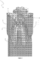
- Figure 2 shows a certain embodiment of a tri cone drill bit 7 according to the present invention.
- the base region 5 is adapted to include a protrusion 8.
- This protrusion 8 is configured to extend from the base region 5 into the clearance, or space, between the base region 5 and the conical cutters 4.
- the protrusion 8 will converge at an apex 9.
- this apex 9 is sharply defined, but in other embodiments, apex 9 may be blunt, or less defined.
- the protrusion 8 and the apex 9 are symmetrically arranged on the base region 5 of the main body portion 2.
- Such a configuration includes the apex 9 being positioned substantially equidistant from each of the legs 3 and the conical cutters 4. Also, in such a configuration, the apex 9 is centred underneath the meeting point of the three conical cutters 4.
- the protrusion 8 of the drill bit 7 is also advantageous when drilling in soft boggy ground. As is the case with particulate cuttings, the protrusion 8 guides the soft ground and cuttings away from the base region 5 more efficiently than the flat base region 5 of the prior art drill bit 1. This will decrease instances of the drill bit becoming plugged by soft material, which can lead to the drill bit (1, 7) becoming bogged in the hole. The bogging of a drill bit (1, 7) is a major problem which can take extensive down time to rectify and can ultimately lead to early bit failure.
- the protrusion 8 of the tri cone drill bit showing in figure 2 is formed from a plurality of sloping faces 11 converging at the apex 9. According to the invention, each sloping face 11 is concave, resulting in ridges 10 being formed between adjacent sloping faces 11.
- the protrusions 8 and/or sloping faces 11 thereof can take any shape desirable. Examples or protrusions 8 listed herein are not exhaustive, but are simply intended to illustrate potential forms.
- the protrusion 8 can take any shape desired, with different shapes potentially offering different advantages in drilling speed, machining cost and wear profiles for different drill mediums, for example.
- a protrusion 8 without a plurality of faces such as a smooth mound or dome.
- a protrusion could have either a concave or convex profile, depending on the application of the drill.
- the protrusion 8 could have a combination of a concave and convex portion, such as protrusion 8 with the shape of a three dimensional Gaussian curve.
- the protrusion 8 could also have flat faces, similar to a pyramid with as many faces as desired for the application. Conical protrusions 8, with or without a sharp apex 9, may also be desirable in some drilling applications.
- Different angles for the sloping face 11 of the protrusion 8 may also find benefit for different applications. For example, when drilling hard ground, it may be advantageous to use a shallow angle, allowing the legs 3 to be larger and hence stronger. In applications such as this, the amount of steel used internally in the drill 7 bit could also be increased to impart additional strength.
- the ridges 10 have been arranged in such a manner as to define clear channels 12. These channels 12 offer a path for cuttings to pass unobstructed past obstacles such as the legs 3 and air outlets 15. This effect is further enhanced by smoothly moulding the legs 3 and air outlets 15 into the ridges 10.
- the sloping face 11 of the protrusion 8 continues through the base region 5 of the main body portion 2, emerging at an outer surface 13 of the main body portion 2. This effectively produces scallops 14 in the outside surface of the main body portion 2 allowing the channels 12 to continue with a steeper gradient than would otherwise be possible.
- the reduction in regrinding due to the present invention may also reduce abrasive wear to the shirt tails 16 of the drill bit 7. These shirt tails 16 protect the bearings 17 of the rotating conical cutters 4. When sealed bearings 17 are used, excessive shirt tail 16 wear causes the bearings 17 to become exposed and leak lubricating fluid, leading to drill failure. As sealed bearings 17 are generally preferred to normal air bearings 17 in mining and oil field applications, the present invention may lead to productivity gains in these industries.
- the air outlets 15 can be shaped to occupy a smaller portion of the path available to drill cuttings to flow away from the drill bit 7.
- the air outlet 15 can be elongated, with a long axis orientated in a direction substantially radial to the longitudinal axis of the main body portion 2.
- the air outlet 15 can be positioned closer to the legs 3 of the drill bit 7. Such an arrangement reduces the resistance to drill cuttings exiting the base region 5 of the drill bit 7, and reduces the regrinding of material returned to the drill hole by entrainment in blast air.
- the elongated air outlet 15 is positioned within a ridge 10 of the protrusion 8. Otherwise stated, the air outlet 15 is positioned outside of a channel 12, formed for the conveyance of drill cuttings and debris away from the drill bit 7. This arrangement completely removes the air outlet 15 from the path of cuttings flowing away from the drill bit 7 by way of the channel 12.
- the air outlet 15 in the present invention may be a simple aperture, as represented in figure 2 , or a nozzle, is desired for the drilling application.
Landscapes
- Engineering & Computer Science (AREA)
- Geology (AREA)
- Life Sciences & Earth Sciences (AREA)
- Mining & Mineral Resources (AREA)
- Physics & Mathematics (AREA)
- Environmental & Geological Engineering (AREA)
- Fluid Mechanics (AREA)
- Mechanical Engineering (AREA)
- General Life Sciences & Earth Sciences (AREA)
- Geochemistry & Mineralogy (AREA)
- Earth Drilling (AREA)
- Processing Of Stones Or Stones Resemblance Materials (AREA)
- Drilling Tools (AREA)
Claims (5)
- Bohrmeißel (7), einschließend:- einen Hauptkörperabschnitt mit drei Beinen (3), die sich davon erstrecken, wobei die drei Beine (3) um einen Umfang des Hauptkörperabschnitts (2) angeordnet sind;- einen Basisbereich (5), der in einem allgemeinen Bereich enthalten ist, in dem die Beine (3) auf den Hauptkörperabschnitt (2) treffen;- eine konische Schneidvorrichtung (4), die drehbar an jedem Bein (3) angebracht ist, wobei die konischen Schneidvorrichtungen (4) so positioniert sind, dass sie einen Zwischenraum zwischen den konischen Schneidvorrichtungen (4) und dem Hauptkörperabschnitt (2) ermöglichen; und- einen oder mehrere Luftauslässe (15), die sich im Basisbereich (5) befinden, wobei sich der oder jeder Luftauslass (15) in einem Bereich zwischen zwei benachbarten Beinen (3) befindet und so konfiguriert ist, dass Luft in Richtung der konischen Schneidvorrichtungen (4) geleitet wird;- einen Vorsprung (8), der sich vom Hauptkörperabschnitt (2) in den Zwischenraum erstreckt, wobei der Bohrmeißel (7) dadurch gekennzeichnet ist, dass- der Vorsprung (8) eine geneigte Oberfläche einschließlich einer Vielzahl von geneigten Oberflächen (11) einschließt, die an einem Scheitelpunkt (9) zusammenlaufen, wobei sich die geneigte Oberfläche durch den Basisbereich (5) fortsetzt und an einer Außenoberfläche (13) des Hauptkörperabschnitts austritt; und- die geneigten Oberflächen (11) konkav sind, so dass Rippen (10) zwischen den konkaven Abschnitten benachbarter geneigter Oberflächen (11) definiert sind, wobei die Beine (3) und der eine oder die mehreren Luftauslässe (15) innerhalb der Rippen (10) positioniert sind, die geneigten Oberflächen (11) dann Kanäle (12) bilden, die durch die Rippen (10) begrenzt sind, damit Bohrgut dort hindurch fließen kann, wobei die Kanäle (12) zwischen den Beinen (3) und dem einen oder den mehreren Luftauslässen (15) verlaufen und sich dort hindurch bis zur Außenoberfläche (13) des Hauptkörperabschnitts (2) fortsetzen, um das Bohrgut so zu führen, dass es ungehindert an den Beinen (3) und den Luftauslässen (15) vorbei verläuft.
- Bohrmeißel (7) nach Anspruch 1, wobei der Scheitelpunkt (9) im Wesentlichen gleich weit von den drei Beinen (3) entfernt ist.
- Bohrmeißel (7) nach Anspruch 2, wobei sich die geneigte Oberfläche zwischen dem Scheitelpunkt (9) und dem Basisbereich (5) des Hauptkörperabschnitts befindet.
- Bohrmeißel (7) nach Anspruch 1, wobei die geneigten Oberflächen (11) vollständig konkav sind und die Rippe (10) zwischen den Abschnitten der konkaven geneigten Oberflächen (11) definieren.
- Bohrmeißel (7) nach einem der Ansprüche 1 bis 4, wobei die Luftauslässe (15) in Form von Düsen vorliegen.
Priority Applications (1)
| Application Number | Priority Date | Filing Date | Title |
|---|---|---|---|
| PL14804527T PL3004516T3 (pl) | 2013-05-27 | 2014-05-27 | Świder wiertniczy |
Applications Claiming Priority (2)
| Application Number | Priority Date | Filing Date | Title |
|---|---|---|---|
| AU2013901881A AU2013901881A0 (en) | 2013-05-27 | Drill bit | |
| PCT/AU2014/050051 WO2014190392A1 (en) | 2013-05-27 | 2014-05-27 | Drill bit |
Publications (3)
| Publication Number | Publication Date |
|---|---|
| EP3004516A1 EP3004516A1 (de) | 2016-04-13 |
| EP3004516A4 EP3004516A4 (de) | 2017-01-25 |
| EP3004516B1 true EP3004516B1 (de) | 2021-07-14 |
Family
ID=51987782
Family Applications (1)
| Application Number | Title | Priority Date | Filing Date |
|---|---|---|---|
| EP14804527.1A Active EP3004516B1 (de) | 2013-05-27 | 2014-05-27 | Bohrmeissel |
Country Status (8)
| Country | Link |
|---|---|
| US (1) | US10323461B2 (de) |
| EP (1) | EP3004516B1 (de) |
| CN (1) | CN105378209B (de) |
| AU (1) | AU2014273848C1 (de) |
| PL (1) | PL3004516T3 (de) |
| PT (1) | PT3004516T (de) |
| WO (1) | WO2014190392A1 (de) |
| ZA (1) | ZA201508647B (de) |
Families Citing this family (1)
| Publication number | Priority date | Publication date | Assignee | Title |
|---|---|---|---|---|
| KR20230071861A (ko) | 2021-11-15 | 2023-05-24 | 삼성디스플레이 주식회사 | 표시 장치 |
Family Cites Families (9)
| Publication number | Priority date | Publication date | Assignee | Title |
|---|---|---|---|---|
| US2901223A (en) * | 1955-11-30 | 1959-08-25 | Hughes Tool Co | Earth boring drill |
| US4189014A (en) * | 1978-08-14 | 1980-02-19 | Smith International, Inc. | Enhanced cross-flow with two jet drilling |
| NO810916L (no) | 1980-03-24 | 1981-09-25 | Reed Rock Bit Co | Borekrone med rulleskjaer. |
| US4546837A (en) * | 1980-03-24 | 1985-10-15 | Reed Tool Company | Drill bit having angled nozzles for improved bit and well bore cleaning |
| US4538691A (en) * | 1984-01-30 | 1985-09-03 | Strata Bit Corporation | Rotary drill bit |
| US4619335A (en) * | 1984-08-16 | 1986-10-28 | Mccullough Doyle W | Enhanced circulation drill bit |
| FR2719626B1 (fr) * | 1994-05-04 | 1996-07-26 | Total Sa | Outil de forage anti-bourrage. |
| WO2009091989A1 (en) | 2008-01-18 | 2009-07-23 | Halliburton Energy Services, Inc . | High performance rock bit grease |
| CN101382045A (zh) * | 2008-07-30 | 2009-03-11 | 江汉石油钻头股份有限公司 | 一种用于水平井和硬地层井的三牙轮钻头 |
-
2014
- 2014-05-27 PL PL14804527T patent/PL3004516T3/pl unknown
- 2014-05-27 EP EP14804527.1A patent/EP3004516B1/de active Active
- 2014-05-27 PT PT14804527T patent/PT3004516T/pt unknown
- 2014-05-27 CN CN201480030164.7A patent/CN105378209B/zh active Active
- 2014-05-27 WO PCT/AU2014/050051 patent/WO2014190392A1/en not_active Ceased
- 2014-05-27 US US14/894,182 patent/US10323461B2/en active Active
- 2014-05-27 AU AU2014273848A patent/AU2014273848C1/en active Active
-
2015
- 2015-11-24 ZA ZA2015/08647A patent/ZA201508647B/en unknown
Also Published As
| Publication number | Publication date |
|---|---|
| AU2014273848C1 (en) | 2019-08-01 |
| CN105378209A (zh) | 2016-03-02 |
| WO2014190392A1 (en) | 2014-12-04 |
| EP3004516A4 (de) | 2017-01-25 |
| CN105378209B (zh) | 2019-01-18 |
| AU2014273848A1 (en) | 2015-11-26 |
| PT3004516T (pt) | 2021-10-25 |
| AU2014273848B2 (en) | 2018-07-05 |
| US10323461B2 (en) | 2019-06-18 |
| US20160123084A1 (en) | 2016-05-05 |
| EP3004516A1 (de) | 2016-04-13 |
| ZA201508647B (en) | 2017-09-27 |
| PL3004516T3 (pl) | 2021-12-27 |
Similar Documents
| Publication | Publication Date | Title |
|---|---|---|
| JP5447130B2 (ja) | クーラント穴付きドリル | |
| EP2902583B1 (de) | Gesteinsschlagbohrmeißel mit Spülnuten | |
| US8517124B2 (en) | PDC drill bit with flute design for better bit cleaning | |
| US8905162B2 (en) | High efficiency hydraulic drill bit | |
| US7083011B2 (en) | Fluid drilling head | |
| AU2017213442B2 (en) | Durable rock bit for blast hole drilling | |
| US20160177630A1 (en) | Extended or raised nozzle for pdc bits | |
| US8020639B2 (en) | Cutting removal system for PDC drill bits | |
| US4189014A (en) | Enhanced cross-flow with two jet drilling | |
| US10323461B2 (en) | Tri cone drill bit | |
| US7913778B2 (en) | Rock bit with hydraulic configuration | |
| US8091654B2 (en) | Rock bit with vectored hydraulic nozzle retention sleeves | |
| AU2015354408B2 (en) | Drill bit | |
| CN204975454U (zh) | 一种平稳型波纹状高精度钻头 | |
| US9617794B2 (en) | Feature to eliminate shale packing/shale evacuation channel | |
| GB2461429A (en) | Rock bit with hydraulics configuration | |
| US20160123086A1 (en) | Anti-balling Drill Bit | |
| CN110998058A (zh) | 具有用于流动优化的切屑通道的岩钻头 |
Legal Events
| Date | Code | Title | Description |
|---|---|---|---|
| PUAI | Public reference made under article 153(3) epc to a published international application that has entered the european phase |
Free format text: ORIGINAL CODE: 0009012 |
|
| 17P | Request for examination filed |
Effective date: 20151127 |
|
| AK | Designated contracting states |
Kind code of ref document: A1 Designated state(s): AL AT BE BG CH CY CZ DE DK EE ES FI FR GB GR HR HU IE IS IT LI LT LU LV MC MK MT NL NO PL PT RO RS SE SI SK SM TR |
|
| AX | Request for extension of the european patent |
Extension state: BA ME |
|
| DAX | Request for extension of the european patent (deleted) | ||
| A4 | Supplementary search report drawn up and despatched |
Effective date: 20170103 |
|
| RIC1 | Information provided on ipc code assigned before grant |
Ipc: E21B 10/18 20060101AFI20161221BHEP |
|
| STAA | Information on the status of an ep patent application or granted ep patent |
Free format text: STATUS: EXAMINATION IS IN PROGRESS |
|
| 17Q | First examination report despatched |
Effective date: 20200706 |
|
| GRAP | Despatch of communication of intention to grant a patent |
Free format text: ORIGINAL CODE: EPIDOSNIGR1 |
|
| STAA | Information on the status of an ep patent application or granted ep patent |
Free format text: STATUS: GRANT OF PATENT IS INTENDED |
|
| INTG | Intention to grant announced |
Effective date: 20210202 |
|
| GRAS | Grant fee paid |
Free format text: ORIGINAL CODE: EPIDOSNIGR3 |
|
| GRAA | (expected) grant |
Free format text: ORIGINAL CODE: 0009210 |
|
| STAA | Information on the status of an ep patent application or granted ep patent |
Free format text: STATUS: THE PATENT HAS BEEN GRANTED |
|
| AK | Designated contracting states |
Kind code of ref document: B1 Designated state(s): AL AT BE BG CH CY CZ DE DK EE ES FI FR GB GR HR HU IE IS IT LI LT LU LV MC MK MT NL NO PL PT RO RS SE SI SK SM TR |
|
| REG | Reference to a national code |
Ref country code: GB Ref legal event code: FG4D |
|
| REG | Reference to a national code |
Ref country code: DE Ref legal event code: R096 Ref document number: 602014078781 Country of ref document: DE |
|
| REG | Reference to a national code |
Ref country code: IE Ref legal event code: FG4D |
|
| REG | Reference to a national code |
Ref country code: AT Ref legal event code: REF Ref document number: 1410794 Country of ref document: AT Kind code of ref document: T Effective date: 20210815 |
|
| REG | Reference to a national code |
Ref country code: PT Ref legal event code: SC4A Ref document number: 3004516 Country of ref document: PT Date of ref document: 20211025 Kind code of ref document: T Free format text: AVAILABILITY OF NATIONAL TRANSLATION Effective date: 20211015 |
|
| REG | Reference to a national code |
Ref country code: SE Ref legal event code: TRGR |
|
| REG | Reference to a national code |
Ref country code: LT Ref legal event code: MG9D |
|
| REG | Reference to a national code |
Ref country code: NL Ref legal event code: MP Effective date: 20210714 |
|
| REG | Reference to a national code |
Ref country code: AT Ref legal event code: MK05 Ref document number: 1410794 Country of ref document: AT Kind code of ref document: T Effective date: 20210714 |
|
| PG25 | Lapsed in a contracting state [announced via postgrant information from national office to epo] |
Ref country code: LT Free format text: LAPSE BECAUSE OF FAILURE TO SUBMIT A TRANSLATION OF THE DESCRIPTION OR TO PAY THE FEE WITHIN THE PRESCRIBED TIME-LIMIT Effective date: 20210714 Ref country code: AT Free format text: LAPSE BECAUSE OF FAILURE TO SUBMIT A TRANSLATION OF THE DESCRIPTION OR TO PAY THE FEE WITHIN THE PRESCRIBED TIME-LIMIT Effective date: 20210714 Ref country code: BG Free format text: LAPSE BECAUSE OF FAILURE TO SUBMIT A TRANSLATION OF THE DESCRIPTION OR TO PAY THE FEE WITHIN THE PRESCRIBED TIME-LIMIT Effective date: 20211014 Ref country code: FI Free format text: LAPSE BECAUSE OF FAILURE TO SUBMIT A TRANSLATION OF THE DESCRIPTION OR TO PAY THE FEE WITHIN THE PRESCRIBED TIME-LIMIT Effective date: 20210714 Ref country code: ES Free format text: LAPSE BECAUSE OF FAILURE TO SUBMIT A TRANSLATION OF THE DESCRIPTION OR TO PAY THE FEE WITHIN THE PRESCRIBED TIME-LIMIT Effective date: 20210714 Ref country code: NL Free format text: LAPSE BECAUSE OF FAILURE TO SUBMIT A TRANSLATION OF THE DESCRIPTION OR TO PAY THE FEE WITHIN THE PRESCRIBED TIME-LIMIT Effective date: 20210714 Ref country code: NO Free format text: LAPSE BECAUSE OF FAILURE TO SUBMIT A TRANSLATION OF THE DESCRIPTION OR TO PAY THE FEE WITHIN THE PRESCRIBED TIME-LIMIT Effective date: 20211014 Ref country code: HR Free format text: LAPSE BECAUSE OF FAILURE TO SUBMIT A TRANSLATION OF THE DESCRIPTION OR TO PAY THE FEE WITHIN THE PRESCRIBED TIME-LIMIT Effective date: 20210714 Ref country code: RS Free format text: LAPSE BECAUSE OF FAILURE TO SUBMIT A TRANSLATION OF THE DESCRIPTION OR TO PAY THE FEE WITHIN THE PRESCRIBED TIME-LIMIT Effective date: 20210714 |
|
| PG25 | Lapsed in a contracting state [announced via postgrant information from national office to epo] |
Ref country code: LV Free format text: LAPSE BECAUSE OF FAILURE TO SUBMIT A TRANSLATION OF THE DESCRIPTION OR TO PAY THE FEE WITHIN THE PRESCRIBED TIME-LIMIT Effective date: 20210714 Ref country code: GR Free format text: LAPSE BECAUSE OF FAILURE TO SUBMIT A TRANSLATION OF THE DESCRIPTION OR TO PAY THE FEE WITHIN THE PRESCRIBED TIME-LIMIT Effective date: 20211015 |
|
| REG | Reference to a national code |
Ref country code: DE Ref legal event code: R097 Ref document number: 602014078781 Country of ref document: DE |
|
| PG25 | Lapsed in a contracting state [announced via postgrant information from national office to epo] |
Ref country code: DK Free format text: LAPSE BECAUSE OF FAILURE TO SUBMIT A TRANSLATION OF THE DESCRIPTION OR TO PAY THE FEE WITHIN THE PRESCRIBED TIME-LIMIT Effective date: 20210714 |
|
| PLBE | No opposition filed within time limit |
Free format text: ORIGINAL CODE: 0009261 |
|
| STAA | Information on the status of an ep patent application or granted ep patent |
Free format text: STATUS: NO OPPOSITION FILED WITHIN TIME LIMIT |
|
| PG25 | Lapsed in a contracting state [announced via postgrant information from national office to epo] |
Ref country code: SM Free format text: LAPSE BECAUSE OF FAILURE TO SUBMIT A TRANSLATION OF THE DESCRIPTION OR TO PAY THE FEE WITHIN THE PRESCRIBED TIME-LIMIT Effective date: 20210714 Ref country code: SK Free format text: LAPSE BECAUSE OF FAILURE TO SUBMIT A TRANSLATION OF THE DESCRIPTION OR TO PAY THE FEE WITHIN THE PRESCRIBED TIME-LIMIT Effective date: 20210714 Ref country code: RO Free format text: LAPSE BECAUSE OF FAILURE TO SUBMIT A TRANSLATION OF THE DESCRIPTION OR TO PAY THE FEE WITHIN THE PRESCRIBED TIME-LIMIT Effective date: 20210714 Ref country code: EE Free format text: LAPSE BECAUSE OF FAILURE TO SUBMIT A TRANSLATION OF THE DESCRIPTION OR TO PAY THE FEE WITHIN THE PRESCRIBED TIME-LIMIT Effective date: 20210714 Ref country code: CZ Free format text: LAPSE BECAUSE OF FAILURE TO SUBMIT A TRANSLATION OF THE DESCRIPTION OR TO PAY THE FEE WITHIN THE PRESCRIBED TIME-LIMIT Effective date: 20210714 Ref country code: AL Free format text: LAPSE BECAUSE OF FAILURE TO SUBMIT A TRANSLATION OF THE DESCRIPTION OR TO PAY THE FEE WITHIN THE PRESCRIBED TIME-LIMIT Effective date: 20210714 |
|
| 26N | No opposition filed |
Effective date: 20220419 |
|
| PG25 | Lapsed in a contracting state [announced via postgrant information from national office to epo] |
Ref country code: IT Free format text: LAPSE BECAUSE OF FAILURE TO SUBMIT A TRANSLATION OF THE DESCRIPTION OR TO PAY THE FEE WITHIN THE PRESCRIBED TIME-LIMIT Effective date: 20210714 |
|
| REG | Reference to a national code |
Ref country code: CH Ref legal event code: PL |
|
| REG | Reference to a national code |
Ref country code: BE Ref legal event code: MM Effective date: 20220531 |
|
| PG25 | Lapsed in a contracting state [announced via postgrant information from national office to epo] |
Ref country code: MC Free format text: LAPSE BECAUSE OF FAILURE TO SUBMIT A TRANSLATION OF THE DESCRIPTION OR TO PAY THE FEE WITHIN THE PRESCRIBED TIME-LIMIT Effective date: 20210714 Ref country code: LU Free format text: LAPSE BECAUSE OF NON-PAYMENT OF DUE FEES Effective date: 20220527 Ref country code: LI Free format text: LAPSE BECAUSE OF NON-PAYMENT OF DUE FEES Effective date: 20220531 Ref country code: CH Free format text: LAPSE BECAUSE OF NON-PAYMENT OF DUE FEES Effective date: 20220531 |
|
| PG25 | Lapsed in a contracting state [announced via postgrant information from national office to epo] |
Ref country code: IE Free format text: LAPSE BECAUSE OF NON-PAYMENT OF DUE FEES Effective date: 20220527 |
|
| PG25 | Lapsed in a contracting state [announced via postgrant information from national office to epo] |
Ref country code: BE Free format text: LAPSE BECAUSE OF NON-PAYMENT OF DUE FEES Effective date: 20220531 |
|
| REG | Reference to a national code |
Ref country code: DE Ref legal event code: R081 Ref document number: 602014078781 Country of ref document: DE Owner name: DRILLTERRA TECHNOLOGIES PTY LTD, MUSCLE CREEK, AU Free format text: FORMER OWNER: HANNS, DAVID, BELMONT, NEW SOUTH WALES, AU |
|
| REG | Reference to a national code |
Ref country code: GB Ref legal event code: 732E Free format text: REGISTERED BETWEEN 20230921 AND 20230927 |
|
| PG25 | Lapsed in a contracting state [announced via postgrant information from national office to epo] |
Ref country code: HU Free format text: LAPSE BECAUSE OF FAILURE TO SUBMIT A TRANSLATION OF THE DESCRIPTION OR TO PAY THE FEE WITHIN THE PRESCRIBED TIME-LIMIT; INVALID AB INITIO Effective date: 20140527 |
|
| PG25 | Lapsed in a contracting state [announced via postgrant information from national office to epo] |
Ref country code: MK Free format text: LAPSE BECAUSE OF FAILURE TO SUBMIT A TRANSLATION OF THE DESCRIPTION OR TO PAY THE FEE WITHIN THE PRESCRIBED TIME-LIMIT Effective date: 20210714 Ref country code: CY Free format text: LAPSE BECAUSE OF FAILURE TO SUBMIT A TRANSLATION OF THE DESCRIPTION OR TO PAY THE FEE WITHIN THE PRESCRIBED TIME-LIMIT Effective date: 20210714 |
|
| PG25 | Lapsed in a contracting state [announced via postgrant information from national office to epo] |
Ref country code: TR Free format text: LAPSE BECAUSE OF FAILURE TO SUBMIT A TRANSLATION OF THE DESCRIPTION OR TO PAY THE FEE WITHIN THE PRESCRIBED TIME-LIMIT Effective date: 20210714 |
|
| PG25 | Lapsed in a contracting state [announced via postgrant information from national office to epo] |
Ref country code: MT Free format text: LAPSE BECAUSE OF FAILURE TO SUBMIT A TRANSLATION OF THE DESCRIPTION OR TO PAY THE FEE WITHIN THE PRESCRIBED TIME-LIMIT Effective date: 20210714 |
|
| PGFP | Annual fee paid to national office [announced via postgrant information from national office to epo] |
Ref country code: PL Payment date: 20250509 Year of fee payment: 12 Ref country code: DE Payment date: 20250509 Year of fee payment: 12 |
|
| PGFP | Annual fee paid to national office [announced via postgrant information from national office to epo] |
Ref country code: GB Payment date: 20250509 Year of fee payment: 12 |
|
| PGFP | Annual fee paid to national office [announced via postgrant information from national office to epo] |
Ref country code: PT Payment date: 20250509 Year of fee payment: 12 |
|
| PGFP | Annual fee paid to national office [announced via postgrant information from national office to epo] |
Ref country code: FR Payment date: 20250509 Year of fee payment: 12 |
|
| PGFP | Annual fee paid to national office [announced via postgrant information from national office to epo] |
Ref country code: SE Payment date: 20250521 Year of fee payment: 12 |