EP3003889B1 - Beverage can end having an arcuate panel wall and curved transition wall - Google Patents
Beverage can end having an arcuate panel wall and curved transition wall Download PDFInfo
- Publication number
- EP3003889B1 EP3003889B1 EP14734646.4A EP14734646A EP3003889B1 EP 3003889 B1 EP3003889 B1 EP 3003889B1 EP 14734646 A EP14734646 A EP 14734646A EP 3003889 B1 EP3003889 B1 EP 3003889B1
- Authority
- EP
- European Patent Office
- Prior art keywords
- degrees
- wall
- beverage
- angle
- panel
- Prior art date
- Legal status (The legal status is an assumption and is not a legal conclusion. Google has not performed a legal analysis and makes no representation as to the accuracy of the status listed.)
- Active
Links
Images

Classifications
-
- B—PERFORMING OPERATIONS; TRANSPORTING
- B65—CONVEYING; PACKING; STORING; HANDLING THIN OR FILAMENTARY MATERIAL
- B65D—CONTAINERS FOR STORAGE OR TRANSPORT OF ARTICLES OR MATERIALS, e.g. BAGS, BARRELS, BOTTLES, BOXES, CANS, CARTONS, CRATES, DRUMS, JARS, TANKS, HOPPERS, FORWARDING CONTAINERS; ACCESSORIES, CLOSURES, OR FITTINGS THEREFOR; PACKAGING ELEMENTS; PACKAGES
- B65D17/00—Rigid or semi-rigid containers specially constructed to be opened by cutting or piercing, or by tearing of frangible members or portions
-
- B—PERFORMING OPERATIONS; TRANSPORTING
- B65—CONVEYING; PACKING; STORING; HANDLING THIN OR FILAMENTARY MATERIAL
- B65D—CONTAINERS FOR STORAGE OR TRANSPORT OF ARTICLES OR MATERIALS, e.g. BAGS, BARRELS, BOTTLES, BOXES, CANS, CARTONS, CRATES, DRUMS, JARS, TANKS, HOPPERS, FORWARDING CONTAINERS; ACCESSORIES, CLOSURES, OR FITTINGS THEREFOR; PACKAGING ELEMENTS; PACKAGES
- B65D7/00—Containers having bodies formed by interconnecting or uniting two or more rigid, or substantially rigid, components made wholly or mainly of metal
- B65D7/12—Containers having bodies formed by interconnecting or uniting two or more rigid, or substantially rigid, components made wholly or mainly of metal characterised by wall construction or by connections between walls
- B65D7/34—Containers having bodies formed by interconnecting or uniting two or more rigid, or substantially rigid, components made wholly or mainly of metal characterised by wall construction or by connections between walls with permanent connections between walls
- B65D7/36—Containers having bodies formed by interconnecting or uniting two or more rigid, or substantially rigid, components made wholly or mainly of metal characterised by wall construction or by connections between walls with permanent connections between walls formed by rolling, or by rolling and pressing
-
- B—PERFORMING OPERATIONS; TRANSPORTING
- B21—MECHANICAL METAL-WORKING WITHOUT ESSENTIALLY REMOVING MATERIAL; PUNCHING METAL
- B21D—WORKING OR PROCESSING OF SHEET METAL OR METAL TUBES, RODS OR PROFILES WITHOUT ESSENTIALLY REMOVING MATERIAL; PUNCHING METAL
- B21D51/00—Making hollow objects
- B21D51/16—Making hollow objects characterised by the use of the objects
- B21D51/26—Making hollow objects characterised by the use of the objects cans or tins; Closing same in a permanent manner
- B21D51/2653—Methods or machines for closing cans by applying caps or bottoms
- B21D51/2661—Sealing or closing means therefor
-
- B—PERFORMING OPERATIONS; TRANSPORTING
- B65—CONVEYING; PACKING; STORING; HANDLING THIN OR FILAMENTARY MATERIAL
- B65D—CONTAINERS FOR STORAGE OR TRANSPORT OF ARTICLES OR MATERIALS, e.g. BAGS, BARRELS, BOTTLES, BOXES, CANS, CARTONS, CRATES, DRUMS, JARS, TANKS, HOPPERS, FORWARDING CONTAINERS; ACCESSORIES, CLOSURES, OR FITTINGS THEREFOR; PACKAGING ELEMENTS; PACKAGES
- B65D17/00—Rigid or semi-rigid containers specially constructed to be opened by cutting or piercing, or by tearing of frangible members or portions
- B65D17/06—Integral, or permanently secured, end or side closures
- B65D17/08—Closures secured by folding or rolling and pressing
-
- B—PERFORMING OPERATIONS; TRANSPORTING
- B65—CONVEYING; PACKING; STORING; HANDLING THIN OR FILAMENTARY MATERIAL
- B65D—CONTAINERS FOR STORAGE OR TRANSPORT OF ARTICLES OR MATERIALS, e.g. BAGS, BARRELS, BOTTLES, BOXES, CANS, CARTONS, CRATES, DRUMS, JARS, TANKS, HOPPERS, FORWARDING CONTAINERS; ACCESSORIES, CLOSURES, OR FITTINGS THEREFOR; PACKAGING ELEMENTS; PACKAGES
- B65D2517/00—Containers specially constructed to be opened by cutting, piercing or tearing of wall portions, e.g. preserving cans or tins
- B65D2517/0001—Details
- B65D2517/0058—Other details of container end panel
- B65D2517/0059—General cross-sectional shape of container end panel
- B65D2517/0061—U-shaped
- B65D2517/0062—U-shaped and provided with an additional U-shaped peripheral channel
Definitions
- This invention relates to a container technology, and more particularly to a can end for a beverage can and methods for seaming a beverage can end to a can body.
- Modern beverage cans include a beverage can body that is drawn and ironed from aluminum stock and a beverage can end that is attached to the body by a double seam.
- the assignee of the present invention developed lightweight beverage ends, which are generally described in United States Patent Numbers 8328041 , 7370774 , and 8157119 . Some of the ends generally described in the patents are marketed under the trade name SuperEndTM.
- Competitors have also developed lightweight ends that often incorporate features developed for SuperEnd.
- United States Patent Numbers 7673768 and 8313004 disclose various lightweight ends, some of which have been commercialized.
- WO2012/039433 also describes can ends.
- Modern, lightweight beverage ends are rated to withstand internal can pressurization, as measured by a buckle performance test, often of 85 psi (5.86 bar) or more. Failure often includes loss of the circular profile and buckling of the end which, ultimately, leads to eversion of the end profile. Failure may be initiated by dropping or distorting the can end, or by overpressure within the container, such as when the can undergoes thermal processing or is subjected to high ambient temperature.
- a version of an end developed by Container Development Limited and marketed by Ball Corporation has been found to have problems with consistency of the seam dimensions upon double seaming to a beverage can.
- an end and corresponding method provide an end that is lightweight, can be used with a current, conventional chuck, and is believed to provide for reliable and consistent seams.
- the present invention is not limited to these aspects, but rather encompasses other aspects of the end and combination of features disclosed in the description and stated in the claims.
- a beverage can end comprising a center panel; an arcuate panel wall that extends outwardly from the center panel; an upwardly-opening annular bead merging into the arcuate panel wall; a lower transition wall extending from an outer end of the annular bead, the lower transition wall being inclined at an angle A2 that is less than 11 degrees from a vertical axis defined when the can end is conventionally oriented; a curved upper transition wall extending outwardly from an upper end of the lower transition wall, the lower transition wall yielding smoothly to the upper transition wall; a substantially flat intermediate wall; a substantially flat upper wall that is inclined more than the intermediate wall and that is inclined at an angle A4 that is at least 13 degrees from said axis; a juncture formed between the intermediate wall and the upper wall; a seaming panel extending from an upper end of the upper wall, the seaming panel having a radius R4 of between 0.050 inches (1.27 mm) and 0.060 inches (1.524 mm
- angle A2 of the lower transition wall is between 1 degree and 10 degrees, more preferably between 2 degrees and 8 degrees, more preferably, between 3 degrees and 6 degrees, and, in the embodiment in the figures, about 5.5 degrees.
- intermediate wall is inclined at an angle A3 that is between 50 degrees and 63 degrees, more preferably between 52 degrees and 60 degrees, and, in the embodiment in the figures, about 55 degrees.
- the upper wall angle A4 is at least 13 degrees, more preferably at least 15 degrees, and, in the embodiment in the figures, approximately 16 degrees.
- the panel wall is inclined at an angle A1 of between 30 degrees and 60 degrees, more preferably between 40 degrees and 50 degrees, and, in the embodiment in the figures, about 45 degrees.
- the bead may be approximately symmetric about a vertical centerline.
- a beverage can end and beverage can body combination included the unseamed beverage end according to the first aspect above and a beverage can body.
- the beverage can body prior to seaming includes a flange that matches the seaming panel shape and dimensions of the seaming panel radius.
- the seaming panel has a radius R4 that is the sum of the radius R3 of the flange and the flange metal thickness t.
- a method for seaming a beverage can end and a beverage can body together includes placing the beverage can end on to a beverage can body, which has a flange that matches the seaming panel shape and dimensions of the seaming panel radius, and the seaming panel having a radius R4 that is the sum of the radius R3 of the flange and the flange metal thickness t.
- the method includes the step of bringing a chuck into engagement with an exterior surface of the end such that a lowermost point of an anvil of the chuck contacts the juncture of the end and engaging the curl of the end with seaming rolls such that the upper wall is bent up by at least 9 degrees.
- the upper wall angle A4 is at least 13 degrees. More preferably, the upper wall angle A4 is at least 15 degrees and the upper wall is bent up by at least 11 degrees, and more preferably the upper wall angle A4 is approximately 16 degrees and the upper wall is bent up by at least 13 degrees.
- the disclosed beverage can end preferably is for double seaming by conventional seaming equipment onto a drawn and ironed beverage can body, such as a necked 211 sized can body.
- the end preferably is a 206, 204, or 200 size, and the inventors contemplate other industry-accepted sizes.
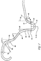
- Figure 1 illustrates a cross section of a beverage can end 10 illustrating aspects of the present invention.
- Can end 10 is a cross section of an end shell prepared by encasing a sample end in a polymer, cutting the shell into a cross section, and then photographing, enlarging, and enhancing the image. Accordingly, can end 10 is dimensionally accurate for an embodiment of the present invention.
- Can end 10 includes a center panel 12, a curved panel wall 14, a bead 18, a lower transition wall 20, a upper transition wall 22, a intermediate wall 24, a juncture 26, an upper wall 28, a seaming panel 30, and a curl 32.
- Center panel 12 is circular and includes a pour opening and an opening mechanism, each of which preferably is conventional.
- the pour opening may be formed by a score (not shown in the figures) in the shape known in the beverage end industry as a large opening end (LOE).
- the opening mechanism preferably is a convention stay-on-tab (SOT).
- Center panel 12 in the illustration of Figure 1 is not flat because the cross section shows beading, as will be understood by persons familiar with can end center panels. The particular end shown in Figure 1 is referred to as a DRT style.
- shell is used in this disclosure to refer to the product of a shell press, including the finished profile.
- end is used to refer to the shell after a tab has been applied in a conversion press.
- Can end 10 is illustrated in its unseamed state, and the present invention encompasses a combination can body and end combination in the seamed state, the method for forming the combination, and the can body and end combination in which the unseamed end is positioned on the can body ready for seaming.
- a curved panel wall 14 extends about center panel 12 such that in transverse cross section, as shown in Figure 1 , panel wall extends outwardly and downwardly from center panel 12.
- the terms “outwardly” and “inwardly” refer to a radial direction.
- the terms “upwardly” and “downwardly” refer to vertical direction as the end is conventionally oriented.
- the terms indicating radial direction and vertical direction are not exclusive. Nor do the terms indicate one is dominant over the other. For example, a part A that extends radially outwardly and from another part B and also extends upwardly from part B by a few degrees may be described in this disclosure and claims as extending outwardly, as extending upwardly, or as both extending upwardly and outwardly.
- wall 14 may be defined by end points 40 and 42, which are on wall 14 where wall 14 merges with radii R1 and R2.
- radii R1 and R2 are between 0.015" inches (0.381 mm) and 0.025" inches (0.635 mm).
- the present invention is not limited to transitions at 40 and 42 that are formed by a single radius.
- wall 14 may merge smoothly into center panel 12 and the inner bead wall of bead 18 or other configurations.
- points 40 and/or 42 may be identified by eye.
- a line drawn between end points 40 and 42 may be inclined at an angle A1 that is between 30 degrees and 60 degrees, preferably between 40 degrees and 50 degrees, and most preferably about 45 degrees.
- Annular countersink bead 18 preferably forms a semi-circle and preferably is approximately symmetric (within ordinary manufacturing tolerances) about a vertical centerline V-CS.
- the horizontal dashed line in Figure 2 defines the boundaries of the semi-circular shaped bead 18.
- the horizontal dashed line may be drawn horizontally from transition point 44 (defined below), from the point at which inner portion of the bead 18 yields to radius R2, or a point chosen such that bead 18 is symmetrical, as will be understood by persons familiar with end reinforcing bead configurations.
- the semi-circular shape of bead 18 is beneficial in embodiments in which a chuck (now shown in the figures) is positioned in the bead during the seaming process.
- Lower transition wall 20 extends upwardly from an outer portion of bead 18.
- Preferably lower transition wall 20 is straight or nearly straight and is defined between transition points 44 and 46.
- a line between transition points 44 and 46 is inclined from vertical at an angle A2 that is less than 11 degrees, preferably less than 10 degrees, more preferably between 2 degrees and 8 degrees or between 3 degrees and 6 degrees, and in the embodiment shown in the figures about 5.5 degrees.
- a curved upper transition wall 22 extends from transition 46 to yield to a substantially flat intermediate wall portion 24.
- Intermediate wall portion 24 merges into upper wall portion 28 at juncture 26.
- Intermediate wall portion 24 preferably is substantially straight and inclined a preferred angle A3 ( Figure 2 ) of between 50 degrees and 63 degrees, more preferably between 52 and 60 degrees, and in most preferably about 55 degrees.
- Upper wall portion wall 28 is substantially straight above a transition portion at junction 26 such that a line between the end points of upper wall 28 is inclined at an angle A4 of at least 13 degrees, and more preferably at least 15 degrees.
- the upper limit of angle A4 is the practical limit on the bending required in the seamer. Because the angle of a conventional chuck is approximately 4 degrees, the magnitude of the angle of deformation during seaming can be calculated by subtracting 4 degrees from A4, such that the magnitude of deflection can be at least 9 degrees and more preferably at least 11 degrees.
- Seaming panel 30 and curl 32 extend from transition 50.
- Seaming panel 30 has a radius R4.
- a portion of a flange 90 of a can body is shown in a position in which end 10 is in position on flange 90 for seaming.
- the shape of seaming panel 30 matches the shape of flange 90 - that is, there is no significant gap between the upper part of the highly curved flange 90 and the seaming panel 30.
- the radius R4 of the seaming panel is the sum of the radius R3 of the flange and the flange metal thickness t.
- Curl 32 preferably is conventional and is chosen together with seaming roller configuration to achieve an industry suitable double seam at commercial line speeds.
- Can end 10 is configured such that a seaming chuck (not shown in the figures) can extend into bead 18 to contact either the bottom radius of bead 18 and/or the outer wall of bead 18 and a lower portion of lower transition wall 20. Also the chuck will have a point at the lower end of its anvil portion that (optionally) may contact juncture 26. In any regard, upper wall 28 to is bent upwardly and inwardly during seaming.
- a seaming chuck (not shown in the figures) can extend into bead 18 to contact either the bottom radius of bead 18 and/or the outer wall of bead 18 and a lower portion of lower transition wall 20.
- the chuck will have a point at the lower end of its anvil portion that (optionally) may contact juncture 26.
- upper wall 28 to is bent upwardly and inwardly during seaming.
- the materials of the can end preferably is a 5000 series aluminum alloy or a tin plate steel and the materials of the can body preferably is a 3000 series aluminum alloy or a tin plate steel.
Landscapes
- Engineering & Computer Science (AREA)
- Mechanical Engineering (AREA)
- Rigid Containers With Two Or More Constituent Elements (AREA)
- Details Of Rigid Or Semi-Rigid Containers (AREA)
- Cartons (AREA)
- Containers Having Bodies Formed In One Piece (AREA)
- Closures For Containers (AREA)
Applications Claiming Priority (2)
| Application Number | Priority Date | Filing Date | Title |
|---|---|---|---|
| US201361829874P | 2013-05-31 | 2013-05-31 | |
| PCT/US2014/039974 WO2014194058A1 (en) | 2013-05-31 | 2014-05-29 | Beverage can end having an arcuate panel wall and curved transition wall |
Publications (2)
| Publication Number | Publication Date |
|---|---|
| EP3003889A1 EP3003889A1 (en) | 2016-04-13 |
| EP3003889B1 true EP3003889B1 (en) | 2017-04-26 |
Family
ID=51059596
Family Applications (1)
| Application Number | Title | Priority Date | Filing Date |
|---|---|---|---|
| EP14734646.4A Active EP3003889B1 (en) | 2013-05-31 | 2014-05-29 | Beverage can end having an arcuate panel wall and curved transition wall |
Country Status (20)
| Country | Link |
|---|---|
| US (1) | US10919664B2 (enExample) |
| EP (1) | EP3003889B1 (enExample) |
| JP (1) | JP2016520026A (enExample) |
| CN (1) | CN105408216B (enExample) |
| AU (1) | AU2014274115B2 (enExample) |
| BR (1) | BR112015030024B1 (enExample) |
| CA (1) | CA2913916C (enExample) |
| DK (1) | DK3003889T3 (enExample) |
| ES (1) | ES2634522T3 (enExample) |
| JO (1) | JO3258B1 (enExample) |
| MA (1) | MA38689B1 (enExample) |
| MX (1) | MX375335B (enExample) |
| MY (2) | MY174736A (enExample) |
| PL (1) | PL3003889T3 (enExample) |
| RU (1) | RU2655906C2 (enExample) |
| SA (1) | SA515370219B1 (enExample) |
| SG (1) | SG11201509696PA (enExample) |
| TN (1) | TN2015000518A1 (enExample) |
| WO (1) | WO2014194058A1 (enExample) |
| ZA (1) | ZA201508758B (enExample) |
Cited By (1)
| Publication number | Priority date | Publication date | Assignee | Title |
|---|---|---|---|---|
| US10246217B2 (en) | 2001-07-03 | 2019-04-02 | Ball Corporation | Can shell and double-seamed can end |
Families Citing this family (4)
| Publication number | Priority date | Publication date | Assignee | Title |
|---|---|---|---|---|
| WO2014194058A1 (en) | 2013-05-31 | 2014-12-04 | Crown Packaging Technology, Inc. | Beverage can end having an arcuate panel wall and curved transition wall |
| US10246250B2 (en) | 2016-04-21 | 2019-04-02 | Crown Packaging Technology, Inc. | Beverage can having a grommet |
| CN108438434B (zh) * | 2018-04-16 | 2023-12-15 | 苏州斯莱克精密设备股份有限公司 | 一种耐压基本盖、易拉盖以及带易拉盖的易拉罐 |
| US12071280B2 (en) * | 2022-01-05 | 2024-08-27 | Ball Corporation | Metallic end closure for small diameter container |
Family Cites Families (25)
| Publication number | Priority date | Publication date | Assignee | Title |
|---|---|---|---|---|
| US4641761A (en) * | 1983-10-26 | 1987-02-10 | Ball Corporation | Increased strength for metal beverage closure through reforming |
| US4681238A (en) * | 1986-10-03 | 1987-07-21 | Sanchez Ruben G | Re-closure device for pop top containers |
| US5356256A (en) * | 1992-10-02 | 1994-10-18 | Turner Timothy L | Reformed container end |
| GB2291610B (en) * | 1994-07-20 | 1998-12-23 | Metal Box Plc | Containers |
| GB9510515D0 (en) * | 1995-05-24 | 1995-07-19 | Metal Box Plc | Containers |
| US5911511A (en) | 1997-09-26 | 1999-06-15 | Alliedsignal Inc. | Tilting pad foil thrust and journal bearings |
| US5971259A (en) * | 1998-06-26 | 1999-10-26 | Sonoco Development, Inc. | Reduced diameter double seam for a composite container |
| US6561004B1 (en) * | 1999-12-08 | 2003-05-13 | Metal Container Corporation | Can lid closure and method of joining a can lid closure to a can body |
| MXPA04006730A (es) * | 1999-12-08 | 2005-03-31 | Metal Container Corp | EXTREMO DE ENVASE DE BEBIDA METáLICO CON PARED DE EXTREMO DE ENVASE DE BEBIDA METáLICO CON PARED DE BOQUILLA MEJORADA Y BROCA DE AVELLANAR. |
| US8490825B2 (en) * | 1999-12-08 | 2013-07-23 | Metal Container Corporation | Can lid closure and method of joining a can lid closure to a can body |
| US6499622B1 (en) * | 1999-12-08 | 2002-12-31 | Metal Container Corporation, Inc. | Can lid closure and method of joining a can lid closure to a can body |
| US7380684B2 (en) * | 1999-12-08 | 2008-06-03 | Metal Container Corporation | Can lid closure |
| JP2002178072A (ja) * | 2000-12-13 | 2002-06-25 | Daiwa Can Co Ltd | 缶 蓋 |
| US6419110B1 (en) * | 2001-07-03 | 2002-07-16 | Container Development, Ltd. | Double-seamed can end and method for forming |
| US7341163B2 (en) * | 2001-07-03 | 2008-03-11 | Container Development, Ltd. | Can shell and double-seamed can end |
| WO2003004716A2 (en) * | 2001-07-03 | 2003-01-16 | Container Development, Ltd. | Can shell and double-seamed can end |
| US7819275B2 (en) * | 2001-07-03 | 2010-10-26 | Container Development, Ltd. | Can shell and double-seamed can end |
| JP4388726B2 (ja) * | 2002-01-15 | 2009-12-24 | 東洋製罐株式会社 | 缶蓋 |
| EP1361164A1 (en) | 2002-04-22 | 2003-11-12 | Crown Cork & Seal Technologies Corporation | Can end |
| US7591392B2 (en) * | 2002-04-22 | 2009-09-22 | Crown Packaging Technology, Inc. | Can end |
| JP4574285B2 (ja) * | 2004-09-01 | 2010-11-04 | ユニバーサル製缶株式会社 | 缶蓋 |
| US20060071005A1 (en) * | 2004-09-27 | 2006-04-06 | Bulso Joseph D | Container end closure with improved chuck wall and countersink |
| WO2012039433A1 (ja) * | 2010-09-22 | 2012-03-29 | ユニバーサル製缶株式会社 | 缶蓋 |
| US8727169B2 (en) * | 2010-11-18 | 2014-05-20 | Ball Corporation | Metallic beverage can end closure with offset countersink |
| WO2014194058A1 (en) | 2013-05-31 | 2014-12-04 | Crown Packaging Technology, Inc. | Beverage can end having an arcuate panel wall and curved transition wall |
-
2014
- 2014-05-29 WO PCT/US2014/039974 patent/WO2014194058A1/en not_active Ceased
- 2014-05-29 SG SG11201509696PA patent/SG11201509696PA/en unknown
- 2014-05-29 RU RU2015156480A patent/RU2655906C2/ru active
- 2014-05-29 ES ES14734646.4T patent/ES2634522T3/es active Active
- 2014-05-29 MX MX2015016412A patent/MX375335B/es active IP Right Grant
- 2014-05-29 PL PL14734646T patent/PL3003889T3/pl unknown
- 2014-05-29 MY MYPI2015704282A patent/MY174736A/en unknown
- 2014-05-29 MY MYPI2020002271A patent/MY205618A/en unknown
- 2014-05-29 EP EP14734646.4A patent/EP3003889B1/en active Active
- 2014-05-29 DK DK14734646.4T patent/DK3003889T3/en active
- 2014-05-29 JP JP2016516811A patent/JP2016520026A/ja active Pending
- 2014-05-29 CA CA2913916A patent/CA2913916C/en active Active
- 2014-05-29 BR BR112015030024-3A patent/BR112015030024B1/pt active IP Right Grant
- 2014-05-29 AU AU2014274115A patent/AU2014274115B2/en active Active
- 2014-05-29 CN CN201480043538.9A patent/CN105408216B/zh active Active
- 2014-05-29 TN TN2015000518A patent/TN2015000518A1/en unknown
- 2014-05-30 US US14/291,298 patent/US10919664B2/en active Active
- 2014-06-01 JO JOP/2014/0179A patent/JO3258B1/ar active
-
2015
- 2015-11-30 SA SA515370219A patent/SA515370219B1/ar unknown
- 2015-11-30 ZA ZA2015/08758A patent/ZA201508758B/en unknown
- 2015-12-16 MA MA38689A patent/MA38689B1/fr unknown
Non-Patent Citations (1)
| Title |
|---|
| None * |
Cited By (1)
| Publication number | Priority date | Publication date | Assignee | Title |
|---|---|---|---|---|
| US10246217B2 (en) | 2001-07-03 | 2019-04-02 | Ball Corporation | Can shell and double-seamed can end |
Also Published As
| Publication number | Publication date |
|---|---|
| MA38689A1 (fr) | 2016-06-30 |
| HK1220958A1 (zh) | 2017-05-19 |
| MY205618A (en) | 2024-10-30 |
| WO2014194058A1 (en) | 2014-12-04 |
| MA38689B1 (fr) | 2017-01-31 |
| US20140353318A1 (en) | 2014-12-04 |
| ZA201508758B (en) | 2019-12-18 |
| MX2015016412A (es) | 2016-03-03 |
| RU2015156480A (ru) | 2017-07-05 |
| BR112015030024B1 (pt) | 2021-02-23 |
| CN105408216A (zh) | 2016-03-16 |
| BR112015030024A2 (pt) | 2017-07-25 |
| CA2913916C (en) | 2021-06-22 |
| SA515370219B1 (ar) | 2019-10-03 |
| MX375335B (es) | 2025-03-06 |
| RU2655906C2 (ru) | 2018-05-29 |
| JO3258B1 (ar) | 2018-09-16 |
| DK3003889T3 (en) | 2017-08-14 |
| SG11201509696PA (en) | 2015-12-30 |
| TN2015000518A1 (en) | 2016-06-29 |
| PL3003889T3 (pl) | 2017-09-29 |
| JP2016520026A (ja) | 2016-07-11 |
| CA2913916A1 (en) | 2014-12-04 |
| CN105408216B (zh) | 2018-03-23 |
| EP3003889A1 (en) | 2016-04-13 |
| ES2634522T3 (es) | 2017-09-28 |
| US10919664B2 (en) | 2021-02-16 |
| MY174736A (en) | 2020-05-12 |
| AU2014274115A1 (en) | 2015-12-17 |
| AU2014274115B2 (en) | 2018-01-18 |
Similar Documents
| Publication | Publication Date | Title |
|---|---|---|
| US12139317B2 (en) | Can end | |
| EP3003889B1 (en) | Beverage can end having an arcuate panel wall and curved transition wall | |
| EP2849900B1 (en) | Container, and selectively formed shell, and tooling and associated method for providing same | |
| US7472575B2 (en) | Non-circular can end with corner-mounted tab and tooling and a conversion press for providing same | |
| EP3423366B1 (en) | Concave can end | |
| US4685322A (en) | Method of forming a drawn and redrawn container body | |
| JP4203016B2 (ja) | 缶エンド、缶エンドを作製するための工具、及び加工された缶エンドを缶胴に装着するためのシーミングチャック | |
| US4031837A (en) | Method of reforming a can end | |
| EP3656482B1 (en) | End closure with coined panel radius and reform step | |
| JP2013514952A (ja) | 強化リベット孔付きタブ、それを提供するためのツーリング及び関連方法 | |
| US4412440A (en) | Process for making container | |
| HK1220958B (en) | Beverae can end having an arcuate panel wall and curved transition wall | |
| WO2025090842A1 (en) | Can end shell ironing systems and methods | |
| JPWO2018062432A1 (ja) | 缶体、缶体の製造方法および缶体の製造装置 |
Legal Events
| Date | Code | Title | Description |
|---|---|---|---|
| PUAI | Public reference made under article 153(3) epc to a published international application that has entered the european phase |
Free format text: ORIGINAL CODE: 0009012 |
|
| 17P | Request for examination filed |
Effective date: 20151214 |
|
| AK | Designated contracting states |
Kind code of ref document: A1 Designated state(s): AL AT BE BG CH CY CZ DE DK EE ES FI FR GB GR HR HU IE IS IT LI LT LU LV MC MK MT NL NO PL PT RO RS SE SI SK SM TR |
|
| AX | Request for extension of the european patent |
Extension state: BA ME |
|
| DAX | Request for extension of the european patent (deleted) | ||
| GRAP | Despatch of communication of intention to grant a patent |
Free format text: ORIGINAL CODE: EPIDOSNIGR1 |
|
| STAA | Information on the status of an ep patent application or granted ep patent |
Free format text: STATUS: GRANT OF PATENT IS INTENDED |
|
| INTG | Intention to grant announced |
Effective date: 20161130 |
|
| GRAS | Grant fee paid |
Free format text: ORIGINAL CODE: EPIDOSNIGR3 |
|
| GRAA | (expected) grant |
Free format text: ORIGINAL CODE: 0009210 |
|
| STAA | Information on the status of an ep patent application or granted ep patent |
Free format text: STATUS: THE PATENT HAS BEEN GRANTED |
|
| AK | Designated contracting states |
Kind code of ref document: B1 Designated state(s): AL AT BE BG CH CY CZ DE DK EE ES FI FR GB GR HR HU IE IS IT LI LT LU LV MC MK MT NL NO PL PT RO RS SE SI SK SM TR |
|
| REG | Reference to a national code |
Ref country code: GB Ref legal event code: FG4D |
|
| REG | Reference to a national code |
Ref country code: CH Ref legal event code: EP |
|
| REG | Reference to a national code |
Ref country code: AT Ref legal event code: REF Ref document number: 887665 Country of ref document: AT Kind code of ref document: T Effective date: 20170515 |
|
| REG | Reference to a national code |
Ref country code: IE Ref legal event code: FG4D |
|
| REG | Reference to a national code |
Ref country code: FR Ref legal event code: PLFP Year of fee payment: 4 |
|
| REG | Reference to a national code |
Ref country code: DE Ref legal event code: R096 Ref document number: 602014009081 Country of ref document: DE |
|
| REG | Reference to a national code |
Ref country code: NL Ref legal event code: FP |
|
| REG | Reference to a national code |
Ref country code: SE Ref legal event code: TRGR |
|
| REG | Reference to a national code |
Ref country code: DK Ref legal event code: T3 Effective date: 20170809 |
|
| REG | Reference to a national code |
Ref country code: LT Ref legal event code: MG4D |
|
| REG | Reference to a national code |
Ref country code: ES Ref legal event code: FG2A Ref document number: 2634522 Country of ref document: ES Kind code of ref document: T3 Effective date: 20170928 |
|
| PG25 | Lapsed in a contracting state [announced via postgrant information from national office to epo] |
Ref country code: NO Free format text: LAPSE BECAUSE OF FAILURE TO SUBMIT A TRANSLATION OF THE DESCRIPTION OR TO PAY THE FEE WITHIN THE PRESCRIBED TIME-LIMIT Effective date: 20170726 Ref country code: LT Free format text: LAPSE BECAUSE OF FAILURE TO SUBMIT A TRANSLATION OF THE DESCRIPTION OR TO PAY THE FEE WITHIN THE PRESCRIBED TIME-LIMIT Effective date: 20170426 Ref country code: HR Free format text: LAPSE BECAUSE OF FAILURE TO SUBMIT A TRANSLATION OF THE DESCRIPTION OR TO PAY THE FEE WITHIN THE PRESCRIBED TIME-LIMIT Effective date: 20170426 |
|
| PG25 | Lapsed in a contracting state [announced via postgrant information from national office to epo] |
Ref country code: LV Free format text: LAPSE BECAUSE OF FAILURE TO SUBMIT A TRANSLATION OF THE DESCRIPTION OR TO PAY THE FEE WITHIN THE PRESCRIBED TIME-LIMIT Effective date: 20170426 Ref country code: RS Free format text: LAPSE BECAUSE OF FAILURE TO SUBMIT A TRANSLATION OF THE DESCRIPTION OR TO PAY THE FEE WITHIN THE PRESCRIBED TIME-LIMIT Effective date: 20170426 Ref country code: BG Free format text: LAPSE BECAUSE OF FAILURE TO SUBMIT A TRANSLATION OF THE DESCRIPTION OR TO PAY THE FEE WITHIN THE PRESCRIBED TIME-LIMIT Effective date: 20170726 Ref country code: IS Free format text: LAPSE BECAUSE OF FAILURE TO SUBMIT A TRANSLATION OF THE DESCRIPTION OR TO PAY THE FEE WITHIN THE PRESCRIBED TIME-LIMIT Effective date: 20170826 |
|
| REG | Reference to a national code |
Ref country code: SK Ref legal event code: T3 Ref document number: E 24657 Country of ref document: SK |
|
| REG | Reference to a national code |
Ref country code: CH Ref legal event code: PL |
|
| REG | Reference to a national code |
Ref country code: DE Ref legal event code: R097 Ref document number: 602014009081 Country of ref document: DE |
|
| PG25 | Lapsed in a contracting state [announced via postgrant information from national office to epo] |
Ref country code: MC Free format text: LAPSE BECAUSE OF FAILURE TO SUBMIT A TRANSLATION OF THE DESCRIPTION OR TO PAY THE FEE WITHIN THE PRESCRIBED TIME-LIMIT Effective date: 20170426 Ref country code: EE Free format text: LAPSE BECAUSE OF FAILURE TO SUBMIT A TRANSLATION OF THE DESCRIPTION OR TO PAY THE FEE WITHIN THE PRESCRIBED TIME-LIMIT Effective date: 20170426 Ref country code: RO Free format text: LAPSE BECAUSE OF FAILURE TO SUBMIT A TRANSLATION OF THE DESCRIPTION OR TO PAY THE FEE WITHIN THE PRESCRIBED TIME-LIMIT Effective date: 20170426 |
|
| REG | Reference to a national code |
Ref country code: GR Ref legal event code: EP Ref document number: 20170402055 Country of ref document: GR Effective date: 20180119 |
|
| REG | Reference to a national code |
Ref country code: IE Ref legal event code: MM4A |
|
| PG25 | Lapsed in a contracting state [announced via postgrant information from national office to epo] |
Ref country code: CH Free format text: LAPSE BECAUSE OF NON-PAYMENT OF DUE FEES Effective date: 20170531 Ref country code: LI Free format text: LAPSE BECAUSE OF NON-PAYMENT OF DUE FEES Effective date: 20170531 Ref country code: SM Free format text: LAPSE BECAUSE OF FAILURE TO SUBMIT A TRANSLATION OF THE DESCRIPTION OR TO PAY THE FEE WITHIN THE PRESCRIBED TIME-LIMIT Effective date: 20170426 |
|
| PLBE | No opposition filed within time limit |
Free format text: ORIGINAL CODE: 0009261 |
|
| STAA | Information on the status of an ep patent application or granted ep patent |
Free format text: STATUS: NO OPPOSITION FILED WITHIN TIME LIMIT |
|
| PG25 | Lapsed in a contracting state [announced via postgrant information from national office to epo] |
Ref country code: LU Free format text: LAPSE BECAUSE OF NON-PAYMENT OF DUE FEES Effective date: 20170529 |
|
| 26N | No opposition filed |
Effective date: 20180129 |
|
| REG | Reference to a national code |
Ref country code: BE Ref legal event code: MM Effective date: 20170531 |
|
| PG25 | Lapsed in a contracting state [announced via postgrant information from national office to epo] |
Ref country code: IE Free format text: LAPSE BECAUSE OF NON-PAYMENT OF DUE FEES Effective date: 20170529 |
|
| REG | Reference to a national code |
Ref country code: FR Ref legal event code: PLFP Year of fee payment: 5 |
|
| PG25 | Lapsed in a contracting state [announced via postgrant information from national office to epo] |
Ref country code: SI Free format text: LAPSE BECAUSE OF FAILURE TO SUBMIT A TRANSLATION OF THE DESCRIPTION OR TO PAY THE FEE WITHIN THE PRESCRIBED TIME-LIMIT Effective date: 20170426 |
|
| PG25 | Lapsed in a contracting state [announced via postgrant information from national office to epo] |
Ref country code: BE Free format text: LAPSE BECAUSE OF NON-PAYMENT OF DUE FEES Effective date: 20170531 |
|
| PG25 | Lapsed in a contracting state [announced via postgrant information from national office to epo] |
Ref country code: MT Free format text: LAPSE BECAUSE OF NON-PAYMENT OF DUE FEES Effective date: 20170529 |
|
| PG25 | Lapsed in a contracting state [announced via postgrant information from national office to epo] |
Ref country code: HU Free format text: LAPSE BECAUSE OF FAILURE TO SUBMIT A TRANSLATION OF THE DESCRIPTION OR TO PAY THE FEE WITHIN THE PRESCRIBED TIME-LIMIT; INVALID AB INITIO Effective date: 20140529 |
|
| PG25 | Lapsed in a contracting state [announced via postgrant information from national office to epo] |
Ref country code: CY Free format text: LAPSE BECAUSE OF FAILURE TO SUBMIT A TRANSLATION OF THE DESCRIPTION OR TO PAY THE FEE WITHIN THE PRESCRIBED TIME-LIMIT Effective date: 20170426 |
|
| PG25 | Lapsed in a contracting state [announced via postgrant information from national office to epo] |
Ref country code: MK Free format text: LAPSE BECAUSE OF FAILURE TO SUBMIT A TRANSLATION OF THE DESCRIPTION OR TO PAY THE FEE WITHIN THE PRESCRIBED TIME-LIMIT Effective date: 20170426 |
|
| REG | Reference to a national code |
Ref country code: AT Ref legal event code: UEP Ref document number: 887665 Country of ref document: AT Kind code of ref document: T Effective date: 20170426 |
|
| PG25 | Lapsed in a contracting state [announced via postgrant information from national office to epo] |
Ref country code: PT Free format text: LAPSE BECAUSE OF FAILURE TO SUBMIT A TRANSLATION OF THE DESCRIPTION OR TO PAY THE FEE WITHIN THE PRESCRIBED TIME-LIMIT Effective date: 20170426 |
|
| PG25 | Lapsed in a contracting state [announced via postgrant information from national office to epo] |
Ref country code: AL Free format text: LAPSE BECAUSE OF FAILURE TO SUBMIT A TRANSLATION OF THE DESCRIPTION OR TO PAY THE FEE WITHIN THE PRESCRIBED TIME-LIMIT Effective date: 20170426 |
|
| P01 | Opt-out of the competence of the unified patent court (upc) registered |
Effective date: 20230517 |
|
| PGFP | Annual fee paid to national office [announced via postgrant information from national office to epo] |
Ref country code: NL Payment date: 20250521 Year of fee payment: 12 |
|
| PGFP | Annual fee paid to national office [announced via postgrant information from national office to epo] |
Ref country code: FI Payment date: 20250526 Year of fee payment: 12 |
|
| PGFP | Annual fee paid to national office [announced via postgrant information from national office to epo] |
Ref country code: PL Payment date: 20250516 Year of fee payment: 12 Ref country code: DE Payment date: 20250521 Year of fee payment: 12 |
|
| PGFP | Annual fee paid to national office [announced via postgrant information from national office to epo] |
Ref country code: ES Payment date: 20250627 Year of fee payment: 12 Ref country code: GB Payment date: 20250527 Year of fee payment: 12 Ref country code: DK Payment date: 20250526 Year of fee payment: 12 |
|
| PGFP | Annual fee paid to national office [announced via postgrant information from national office to epo] |
Ref country code: IT Payment date: 20250523 Year of fee payment: 12 |
|
| PGFP | Annual fee paid to national office [announced via postgrant information from national office to epo] |
Ref country code: FR Payment date: 20250528 Year of fee payment: 12 |
|
| PGFP | Annual fee paid to national office [announced via postgrant information from national office to epo] |
Ref country code: GR Payment date: 20250523 Year of fee payment: 12 |
|
| PGFP | Annual fee paid to national office [announced via postgrant information from national office to epo] |
Ref country code: AT Payment date: 20250522 Year of fee payment: 12 |
|
| PGFP | Annual fee paid to national office [announced via postgrant information from national office to epo] |
Ref country code: TR Payment date: 20250521 Year of fee payment: 12 Ref country code: SK Payment date: 20250519 Year of fee payment: 12 |
|
| PGFP | Annual fee paid to national office [announced via postgrant information from national office to epo] |
Ref country code: CZ Payment date: 20250520 Year of fee payment: 12 |
|
| PGFP | Annual fee paid to national office [announced via postgrant information from national office to epo] |
Ref country code: SE Payment date: 20250521 Year of fee payment: 12 |