EP3003687B1 - Kühlvorrichtung für die kühlung einer schweissnaht an einer seitenfalte eines folienmaterials in einer sackfüllanlage - Google Patents
Kühlvorrichtung für die kühlung einer schweissnaht an einer seitenfalte eines folienmaterials in einer sackfüllanlage Download PDFInfo
- Publication number
- EP3003687B1 EP3003687B1 EP14725027.8A EP14725027A EP3003687B1 EP 3003687 B1 EP3003687 B1 EP 3003687B1 EP 14725027 A EP14725027 A EP 14725027A EP 3003687 B1 EP3003687 B1 EP 3003687B1
- Authority
- EP
- European Patent Office
- Prior art keywords
- cooling
- cooling device
- film material
- weld
- outlet
- Prior art date
- Legal status (The legal status is an assumption and is not a legal conclusion. Google has not performed a legal analysis and makes no representation as to the accuracy of the status listed.)
- Not-in-force
Links
Images


Classifications
-
- B—PERFORMING OPERATIONS; TRANSPORTING
- B29—WORKING OF PLASTICS; WORKING OF SUBSTANCES IN A PLASTIC STATE IN GENERAL
- B29C—SHAPING OR JOINING OF PLASTICS; SHAPING OF MATERIAL IN A PLASTIC STATE, NOT OTHERWISE PROVIDED FOR; AFTER-TREATMENT OF THE SHAPED PRODUCTS, e.g. REPAIRING
- B29C66/00—General aspects of processes or apparatus for joining preformed parts
- B29C66/01—General aspects dealing with the joint area or with the area to be joined
- B29C66/03—After-treatments in the joint area
- B29C66/034—Thermal after-treatments
- B29C66/0342—Cooling, e.g. transporting through welding and cooling zone
-
- B—PERFORMING OPERATIONS; TRANSPORTING
- B29—WORKING OF PLASTICS; WORKING OF SUBSTANCES IN A PLASTIC STATE IN GENERAL
- B29C—SHAPING OR JOINING OF PLASTICS; SHAPING OF MATERIAL IN A PLASTIC STATE, NOT OTHERWISE PROVIDED FOR; AFTER-TREATMENT OF THE SHAPED PRODUCTS, e.g. REPAIRING
- B29C35/00—Heating, cooling or curing, e.g. crosslinking or vulcanising; Apparatus therefor
- B29C35/16—Cooling
-
- B—PERFORMING OPERATIONS; TRANSPORTING
- B29—WORKING OF PLASTICS; WORKING OF SUBSTANCES IN A PLASTIC STATE IN GENERAL
- B29C—SHAPING OR JOINING OF PLASTICS; SHAPING OF MATERIAL IN A PLASTIC STATE, NOT OTHERWISE PROVIDED FOR; AFTER-TREATMENT OF THE SHAPED PRODUCTS, e.g. REPAIRING
- B29C65/00—Joining or sealing of preformed parts, e.g. welding of plastics materials; Apparatus therefor
- B29C65/02—Joining or sealing of preformed parts, e.g. welding of plastics materials; Apparatus therefor by heating, with or without pressure
-
- B—PERFORMING OPERATIONS; TRANSPORTING
- B29—WORKING OF PLASTICS; WORKING OF SUBSTANCES IN A PLASTIC STATE IN GENERAL
- B29C—SHAPING OR JOINING OF PLASTICS; SHAPING OF MATERIAL IN A PLASTIC STATE, NOT OTHERWISE PROVIDED FOR; AFTER-TREATMENT OF THE SHAPED PRODUCTS, e.g. REPAIRING
- B29C66/00—General aspects of processes or apparatus for joining preformed parts
- B29C66/004—Preventing sticking together, e.g. of some areas of the parts to be joined
-
- B—PERFORMING OPERATIONS; TRANSPORTING
- B29—WORKING OF PLASTICS; WORKING OF SUBSTANCES IN A PLASTIC STATE IN GENERAL
- B29C—SHAPING OR JOINING OF PLASTICS; SHAPING OF MATERIAL IN A PLASTIC STATE, NOT OTHERWISE PROVIDED FOR; AFTER-TREATMENT OF THE SHAPED PRODUCTS, e.g. REPAIRING
- B29C66/00—General aspects of processes or apparatus for joining preformed parts
- B29C66/01—General aspects dealing with the joint area or with the area to be joined
- B29C66/05—Particular design of joint configurations
- B29C66/10—Particular design of joint configurations particular design of the joint cross-sections
- B29C66/11—Joint cross-sections comprising a single joint-segment, i.e. one of the parts to be joined comprising a single joint-segment in the joint cross-section
- B29C66/112—Single lapped joints
- B29C66/1122—Single lap to lap joints, i.e. overlap joints
-
- B—PERFORMING OPERATIONS; TRANSPORTING
- B29—WORKING OF PLASTICS; WORKING OF SUBSTANCES IN A PLASTIC STATE IN GENERAL
- B29C—SHAPING OR JOINING OF PLASTICS; SHAPING OF MATERIAL IN A PLASTIC STATE, NOT OTHERWISE PROVIDED FOR; AFTER-TREATMENT OF THE SHAPED PRODUCTS, e.g. REPAIRING
- B29C66/00—General aspects of processes or apparatus for joining preformed parts
- B29C66/01—General aspects dealing with the joint area or with the area to be joined
- B29C66/05—Particular design of joint configurations
- B29C66/10—Particular design of joint configurations particular design of the joint cross-sections
- B29C66/13—Single flanged joints; Fin-type joints; Single hem joints; Edge joints; Interpenetrating fingered joints; Other specific particular designs of joint cross-sections not provided for in groups B29C66/11 - B29C66/12
- B29C66/135—Single hemmed joints, i.e. one of the parts to be joined being hemmed in the joint area
-
- B—PERFORMING OPERATIONS; TRANSPORTING
- B29—WORKING OF PLASTICS; WORKING OF SUBSTANCES IN A PLASTIC STATE IN GENERAL
- B29C—SHAPING OR JOINING OF PLASTICS; SHAPING OF MATERIAL IN A PLASTIC STATE, NOT OTHERWISE PROVIDED FOR; AFTER-TREATMENT OF THE SHAPED PRODUCTS, e.g. REPAIRING
- B29C66/00—General aspects of processes or apparatus for joining preformed parts
- B29C66/40—General aspects of joining substantially flat articles, e.g. plates, sheets or web-like materials; Making flat seams in tubular or hollow articles; Joining single elements to substantially flat surfaces
- B29C66/41—Joining substantially flat articles ; Making flat seams in tubular or hollow articles
- B29C66/43—Joining a relatively small portion of the surface of said articles
- B29C66/431—Joining the articles to themselves
-
- B—PERFORMING OPERATIONS; TRANSPORTING
- B29—WORKING OF PLASTICS; WORKING OF SUBSTANCES IN A PLASTIC STATE IN GENERAL
- B29C—SHAPING OR JOINING OF PLASTICS; SHAPING OF MATERIAL IN A PLASTIC STATE, NOT OTHERWISE PROVIDED FOR; AFTER-TREATMENT OF THE SHAPED PRODUCTS, e.g. REPAIRING
- B29C66/00—General aspects of processes or apparatus for joining preformed parts
- B29C66/80—General aspects of machine operations or constructions and parts thereof
- B29C66/81—General aspects of the pressing elements, i.e. the elements applying pressure on the parts to be joined in the area to be joined, e.g. the welding jaws or clamps
- B29C66/818—General aspects of the pressing elements, i.e. the elements applying pressure on the parts to be joined in the area to be joined, e.g. the welding jaws or clamps characterised by the cooling constructional aspects, or by the thermal or electrical insulating or conducting constructional aspects of the welding jaws or of the clamps ; comprising means for compensating for the thermal expansion of the welding jaws or of the clamps
- B29C66/8181—General aspects of the pressing elements, i.e. the elements applying pressure on the parts to be joined in the area to be joined, e.g. the welding jaws or clamps characterised by the cooling constructional aspects, or by the thermal or electrical insulating or conducting constructional aspects of the welding jaws or of the clamps ; comprising means for compensating for the thermal expansion of the welding jaws or of the clamps characterised by the cooling constructional aspects
-
- B—PERFORMING OPERATIONS; TRANSPORTING
- B29—WORKING OF PLASTICS; WORKING OF SUBSTANCES IN A PLASTIC STATE IN GENERAL
- B29C—SHAPING OR JOINING OF PLASTICS; SHAPING OF MATERIAL IN A PLASTIC STATE, NOT OTHERWISE PROVIDED FOR; AFTER-TREATMENT OF THE SHAPED PRODUCTS, e.g. REPAIRING
- B29C66/00—General aspects of processes or apparatus for joining preformed parts
- B29C66/80—General aspects of machine operations or constructions and parts thereof
- B29C66/84—Specific machine types or machines suitable for specific applications
- B29C66/849—Packaging machines
-
- B—PERFORMING OPERATIONS; TRANSPORTING
- B65—CONVEYING; PACKING; STORING; HANDLING THIN OR FILAMENTARY MATERIAL
- B65B—MACHINES, APPARATUS OR DEVICES FOR, OR METHODS OF, PACKAGING ARTICLES OR MATERIALS; UNPACKING
- B65B1/00—Packaging fluent solid material, e.g. powders, granular or loose fibrous material, loose masses of small articles, in individual containers or receptacles, e.g. bags, sacks, boxes, cartons, cans, or jars
- B65B1/02—Machines characterised by the incorporation of means for making the containers or receptacles
-
- B—PERFORMING OPERATIONS; TRANSPORTING
- B65—CONVEYING; PACKING; STORING; HANDLING THIN OR FILAMENTARY MATERIAL
- B65B—MACHINES, APPARATUS OR DEVICES FOR, OR METHODS OF, PACKAGING ARTICLES OR MATERIALS; UNPACKING
- B65B51/00—Devices for, or methods of, sealing or securing package folds or closures; Devices for gathering or twisting wrappers, or necks of bags
- B65B51/32—Cooling, or cooling and pressing, package closures after heat-sealing
-
- B—PERFORMING OPERATIONS; TRANSPORTING
- B29—WORKING OF PLASTICS; WORKING OF SUBSTANCES IN A PLASTIC STATE IN GENERAL
- B29C—SHAPING OR JOINING OF PLASTICS; SHAPING OF MATERIAL IN A PLASTIC STATE, NOT OTHERWISE PROVIDED FOR; AFTER-TREATMENT OF THE SHAPED PRODUCTS, e.g. REPAIRING
- B29C35/00—Heating, cooling or curing, e.g. crosslinking or vulcanising; Apparatus therefor
- B29C35/16—Cooling
- B29C2035/1616—Cooling using liquids
-
- B—PERFORMING OPERATIONS; TRANSPORTING
- B29—WORKING OF PLASTICS; WORKING OF SUBSTANCES IN A PLASTIC STATE IN GENERAL
- B29C—SHAPING OR JOINING OF PLASTICS; SHAPING OF MATERIAL IN A PLASTIC STATE, NOT OTHERWISE PROVIDED FOR; AFTER-TREATMENT OF THE SHAPED PRODUCTS, e.g. REPAIRING
- B29C35/00—Heating, cooling or curing, e.g. crosslinking or vulcanising; Apparatus therefor
- B29C35/16—Cooling
- B29C2035/1658—Cooling using gas
-
- B—PERFORMING OPERATIONS; TRANSPORTING
- B29—WORKING OF PLASTICS; WORKING OF SUBSTANCES IN A PLASTIC STATE IN GENERAL
- B29C—SHAPING OR JOINING OF PLASTICS; SHAPING OF MATERIAL IN A PLASTIC STATE, NOT OTHERWISE PROVIDED FOR; AFTER-TREATMENT OF THE SHAPED PRODUCTS, e.g. REPAIRING
- B29C66/00—General aspects of processes or apparatus for joining preformed parts
- B29C66/40—General aspects of joining substantially flat articles, e.g. plates, sheets or web-like materials; Making flat seams in tubular or hollow articles; Joining single elements to substantially flat surfaces
- B29C66/41—Joining substantially flat articles ; Making flat seams in tubular or hollow articles
- B29C66/43—Joining a relatively small portion of the surface of said articles
- B29C66/431—Joining the articles to themselves
- B29C66/4312—Joining the articles to themselves for making flat seams in tubular or hollow articles, e.g. transversal seams
-
- B—PERFORMING OPERATIONS; TRANSPORTING
- B29—WORKING OF PLASTICS; WORKING OF SUBSTANCES IN A PLASTIC STATE IN GENERAL
- B29C—SHAPING OR JOINING OF PLASTICS; SHAPING OF MATERIAL IN A PLASTIC STATE, NOT OTHERWISE PROVIDED FOR; AFTER-TREATMENT OF THE SHAPED PRODUCTS, e.g. REPAIRING
- B29C66/00—General aspects of processes or apparatus for joining preformed parts
- B29C66/40—General aspects of joining substantially flat articles, e.g. plates, sheets or web-like materials; Making flat seams in tubular or hollow articles; Joining single elements to substantially flat surfaces
- B29C66/41—Joining substantially flat articles ; Making flat seams in tubular or hollow articles
- B29C66/43—Joining a relatively small portion of the surface of said articles
- B29C66/431—Joining the articles to themselves
- B29C66/4312—Joining the articles to themselves for making flat seams in tubular or hollow articles, e.g. transversal seams
- B29C66/43121—Closing the ends of tubular or hollow single articles, e.g. closing the ends of bags
-
- B—PERFORMING OPERATIONS; TRANSPORTING
- B29—WORKING OF PLASTICS; WORKING OF SUBSTANCES IN A PLASTIC STATE IN GENERAL
- B29C—SHAPING OR JOINING OF PLASTICS; SHAPING OF MATERIAL IN A PLASTIC STATE, NOT OTHERWISE PROVIDED FOR; AFTER-TREATMENT OF THE SHAPED PRODUCTS, e.g. REPAIRING
- B29C66/00—General aspects of processes or apparatus for joining preformed parts
- B29C66/80—General aspects of machine operations or constructions and parts thereof
- B29C66/83—General aspects of machine operations or constructions and parts thereof characterised by the movement of the joining or pressing tools
- B29C66/832—Reciprocating joining or pressing tools
- B29C66/8322—Joining or pressing tools reciprocating along one axis
- B29C66/83221—Joining or pressing tools reciprocating along one axis cooperating reciprocating tools, each tool reciprocating along one axis
-
- B—PERFORMING OPERATIONS; TRANSPORTING
- B29—WORKING OF PLASTICS; WORKING OF SUBSTANCES IN A PLASTIC STATE IN GENERAL
- B29C—SHAPING OR JOINING OF PLASTICS; SHAPING OF MATERIAL IN A PLASTIC STATE, NOT OTHERWISE PROVIDED FOR; AFTER-TREATMENT OF THE SHAPED PRODUCTS, e.g. REPAIRING
- B29C66/00—General aspects of processes or apparatus for joining preformed parts
- B29C66/90—Measuring or controlling the joining process
- B29C66/91—Measuring or controlling the joining process by measuring or controlling the temperature, the heat or the thermal flux
- B29C66/914—Measuring or controlling the joining process by measuring or controlling the temperature, the heat or the thermal flux by controlling or regulating the temperature, the heat or the thermal flux
- B29C66/9141—Measuring or controlling the joining process by measuring or controlling the temperature, the heat or the thermal flux by controlling or regulating the temperature, the heat or the thermal flux by controlling or regulating the temperature
-
- B—PERFORMING OPERATIONS; TRANSPORTING
- B29—WORKING OF PLASTICS; WORKING OF SUBSTANCES IN A PLASTIC STATE IN GENERAL
- B29C—SHAPING OR JOINING OF PLASTICS; SHAPING OF MATERIAL IN A PLASTIC STATE, NOT OTHERWISE PROVIDED FOR; AFTER-TREATMENT OF THE SHAPED PRODUCTS, e.g. REPAIRING
- B29C66/00—General aspects of processes or apparatus for joining preformed parts
- B29C66/90—Measuring or controlling the joining process
- B29C66/91—Measuring or controlling the joining process by measuring or controlling the temperature, the heat or the thermal flux
- B29C66/919—Measuring or controlling the joining process by measuring or controlling the temperature, the heat or the thermal flux characterised by specific temperature, heat or thermal flux values or ranges
-
- B—PERFORMING OPERATIONS; TRANSPORTING
- B31—MAKING ARTICLES OF PAPER, CARDBOARD OR MATERIAL WORKED IN A MANNER ANALOGOUS TO PAPER; WORKING PAPER, CARDBOARD OR MATERIAL WORKED IN A MANNER ANALOGOUS TO PAPER
- B31B—MAKING CONTAINERS OF PAPER, CARDBOARD OR MATERIAL WORKED IN A MANNER ANALOGOUS TO PAPER
- B31B2155/00—Flexible containers made from webs
- B31B2155/001—Flexible containers made from webs by folding webs longitudinally
- B31B2155/0012—Flexible containers made from webs by folding webs longitudinally having their openings facing in the direction of movement
-
- B—PERFORMING OPERATIONS; TRANSPORTING
- B31—MAKING ARTICLES OF PAPER, CARDBOARD OR MATERIAL WORKED IN A MANNER ANALOGOUS TO PAPER; WORKING PAPER, CARDBOARD OR MATERIAL WORKED IN A MANNER ANALOGOUS TO PAPER
- B31B—MAKING CONTAINERS OF PAPER, CARDBOARD OR MATERIAL WORKED IN A MANNER ANALOGOUS TO PAPER
- B31B2155/00—Flexible containers made from webs
- B31B2155/003—Flexible containers made from webs starting from tubular webs
-
- B—PERFORMING OPERATIONS; TRANSPORTING
- B31—MAKING ARTICLES OF PAPER, CARDBOARD OR MATERIAL WORKED IN A MANNER ANALOGOUS TO PAPER; WORKING PAPER, CARDBOARD OR MATERIAL WORKED IN A MANNER ANALOGOUS TO PAPER
- B31B—MAKING CONTAINERS OF PAPER, CARDBOARD OR MATERIAL WORKED IN A MANNER ANALOGOUS TO PAPER
- B31B70/00—Making flexible containers, e.g. envelopes or bags
- B31B70/26—Folding sheets, blanks or webs
- B31B70/262—Folding sheets, blanks or webs involving longitudinally folding, i.e. along a line parallel to the direction of movement
- B31B70/266—Folding sheets, blanks or webs involving longitudinally folding, i.e. along a line parallel to the direction of movement involving gusset-forming
-
- B—PERFORMING OPERATIONS; TRANSPORTING
- B31—MAKING ARTICLES OF PAPER, CARDBOARD OR MATERIAL WORKED IN A MANNER ANALOGOUS TO PAPER; WORKING PAPER, CARDBOARD OR MATERIAL WORKED IN A MANNER ANALOGOUS TO PAPER
- B31B—MAKING CONTAINERS OF PAPER, CARDBOARD OR MATERIAL WORKED IN A MANNER ANALOGOUS TO PAPER
- B31B70/00—Making flexible containers, e.g. envelopes or bags
- B31B70/74—Auxiliary operations
- B31B70/76—Moistening; Drying; Cooling; Heating
-
- B—PERFORMING OPERATIONS; TRANSPORTING
- B65—CONVEYING; PACKING; STORING; HANDLING THIN OR FILAMENTARY MATERIAL
- B65B—MACHINES, APPARATUS OR DEVICES FOR, OR METHODS OF, PACKAGING ARTICLES OR MATERIALS; UNPACKING
- B65B43/00—Forming, feeding, opening or setting-up containers or receptacles in association with packaging
- B65B43/04—Forming flat bags from webs
-
- B—PERFORMING OPERATIONS; TRANSPORTING
- B65—CONVEYING; PACKING; STORING; HANDLING THIN OR FILAMENTARY MATERIAL
- B65B—MACHINES, APPARATUS OR DEVICES FOR, OR METHODS OF, PACKAGING ARTICLES OR MATERIALS; UNPACKING
- B65B51/00—Devices for, or methods of, sealing or securing package folds or closures; Devices for gathering or twisting wrappers, or necks of bags
- B65B51/10—Applying or generating heat or pressure or combinations thereof
- B65B51/26—Devices specially adapted for producing transverse or longitudinal seams in webs or tubes
Definitions
- the present invention relates to a cooling device for cooling a weld on a gusset of a film material in a bag filling plant and a bag filling plant with such a cooling device.
- bag filling systems are used for filling bags with bulk material.
- welding devices are used for sealing the bags.
- these welding devices are used to provide a bottom seam and a top seam for closing the bag.
- welds for the provision of so-called Ecksch spanähten are known.
- Such a weld is arranged only laterally on a film material in the form of a film tube. It serves to close the individual corners of the finished bag against the ingress of bulk material. At the same time there is formed, so to speak, a loop-like projection in order to move the filled bag better.
- cooling channels are provided in known cooling devices, the exit surfaces having outlet openings, which are arranged at an acute angle to each other. Due to the acute-angled arrangement, such a cooling channel can at least partially penetrate into the lateral fold and enable leakage of cooling fluid in the region of the weld seam.
- a disadvantage of known cooling devices is that the exiting cooling fluid can strike the material of the lateral fold of the sheet material essentially freely.
- a substantially vertical outlet direction for the flow of the cooling fluid relative to the adjacent material of the side fold of the film material takes place.
- the exiting cooling material directly, in particular perpendicular, meets the material of the side fold and accordingly acts mechanically deforming or discarding the material of the side fold.
- an overpressure at this point, so that the material of the gusset, based on the interior of the bag portion of the film material, is pressed inwards. This mechanical action can lead to mechanical influence of the film material by unwanted stretching.
- a cooling device serves to cool a weld seam on a gusset of a film material in a bag filling plant.
- the cooling device has a cooling channel for the supply of cooling fluid.
- the cooling channel is provided with a cooling section which has two outlet surfaces aligned at an acute angle to one another, in which outlet openings for the exit of the cooling fluid from the cooling channel are formed.
- the cooling device is characterized in that the cooling section has at least one guide element for the conduction of the cooling fluid. In this case, the at least one guide element aligns the flow direction of the leaked from the outlet openings cooling fluid at an acute angle to the respective exit surface.
- a cooling device therefore forms a decisive difference with regard to the flow direction for the cooling fluid in comparison to known cooling devices.
- a vertical outlet of the cooling fluid is avoided, so that a vertical impact on the arranged in the usual parallel to the exit surfaces side surfaces of the gusset is avoided.
- an acute-angled impingement on the material of the gusset is ensured by the inventive design of the cooling device.
- even a substantially parallel emergence of the cooling fluid is possible parallel to the material surface of the side fold of the film material.
- the mechanical action as has been described in the introduction of this application, significantly reduced to the film material. In particular For example, forming an overpressure and creating a drape will be less likely, or not at all.
- the guide elements can be designed differently in accordance with the invention.
- a common guide element can be provided for a plurality of outlet openings.
- each outlet opening has its own guide element.
- the guide element is formed substantially integrally with the cooling section, so that so to speak guide vanes for individual outlet openings can be arranged in the region of the outlet.
- different guide elements for two or more outlet openings are also conceivable together.
- a cooling device is used in particular in a bag filling plant according to the so-called FFS process (form-fill-seal).
- FFS process form-fill-seal
- the cooling device is used.
- the weld in the form of a corner weld for a cooling device according to the invention is a weld, which is not completely introduced across the width of the film material. Rather, this weld remains in the gusset of the film material and connects superimposed surfaces of this gusset with each other.
- the gusset of a film material is in particular a folded-in side gusset, so when merging this gusset a total of four layers of material of the film material are superimposed. Accordingly, in cross-section, a shape or a contour is formed, which substantially corresponds to the mathematical sum sign (or a large M rotated to the left or to the right).
- a cooling device according to the invention can be further inserted into the gusset, since by the acute-angled arrangement of the individual exit surfaces to each other, so to speak, a wedge is formed, which can be introduced into the gusset in opening action.
- a film material is understood in particular to mean a film web which is conveyed through a bag filling system.
- the film web is preferably formed as a film tube with folded side folds on both sides along the width of the film web.
- the cooling effect is improved by a flow direction according to the invention, since in particular laminar flows can be achieved with low vortices in the interior of the area between the exit surfaces and the material of the gusset.
- cooling fluid both gaseous, and liquid fluids can be used.
- cool ambient air is used. Cooling is preferably carried out in temperature ranges of about 250 ° C and more to less than about 100 ° C.
- An improved cooling serves in addition to increasing the quality of the implementation of the process in the bag filling system to an acceleration of the clock situation, so that the entire bag filling can be operated with higher filling speed.
- the outlet angle between the flow direction of the leaked from the outlet openings cooling fluid and the exit surfaces is less than or equal to about 45 °. ever is smaller the exit angle, the more the flow direction approaches a parallel direction to the exit surfaces and thus also to the laterally adjacent surfaces of the gusset.
- the described effect in terms of a suction effect and at the same time the reduction of the probability of drape are further reduced by the reduction of the exit angle.
- exit angles are used which are even in the range of less than about 30 °. Particularly preferred are ranges for the exit angle of less than about 10 °. In this case, a parallel or substantially parallel orientation of the flow direction to the exit surfaces is particularly preferred.
- the described advantages of the suction effect and the reduction of drape are essentially associated with the reduction of the exit angle. The smaller the exit angle is formed, the more the described inventive advantages come to light.
- the flow direction of the cooling fluid which has leaked out of the outlet openings is aligned along the outlet surfaces, in particular parallel or substantially parallel to the outlet surfaces. It is, so to speak, essentially the optimal or ideal orientation of the flow direction.
- the described advantages of the suction effect and the avoidance of drape are best achieved in this way.
- a multi-part deflection take place, so that the exit z. B. is still substantially perpendicular to the cooling fluid from the outlet openings.
- the guide element comes into operation and deflects the flow direction of the leaked cooling fluid in accordance with the invention stepwise or completely in one step.
- the outlet openings are arranged in the apex region of the outlet surfaces, in particular exactly in the vertex of the outlet surfaces.
- the vertex area is defined by the acute-angled arrangement of the exit surfaces to each other. Form the two exit surfaces legs to each other, the contact between the two exit surfaces will be the smallest distance. This vertex area may be directly the vertex of the corresponding angle between the two exit surfaces. If it is a vertical end plate, ie a blunt peak area, this is away from the real mathematical or geometric vertex, but as a vertex area between the exit surfaces further definable.
- the apex region or the vertex of the exit surfaces is thus that section of the cooling device which projects furthest into the lateral fold.
- the arrangement of the outlet openings exactly in this vertex area or exactly at the vertex brings the cooling fluid deepest in the gusset, so that the distance is extended after exiting the outlet openings along the material of the gusset ideal or maximum.
- the deepest possible penetration of the cooling fluid generates the described suction effect lowest in the gusset, so that the benefits of suction and thus the reduction of wrinkles can be further improved. It is also ensured that the most intensive possible cooling or cooling effect of the introduced cooling fluid can be made available on the largest possible areas of the material of the gusset.
- the at least one guide element is fastened exchangeably on the cooling channel.
- existing cooling channels can be retrofitted with existing cooling devices with guide elements according to the invention. Since the guide element in its outer surface in intensive contact with the film material, so the gusset is, take place here by a sliding action on the outside of the guide the greatest wear.
- the guide element may be formed as a wear part, so that after abrasion on the outer surface, for. B. a sliding reducing layer, for example made of Teflon, a reduction of the wear situation is achieved by the exchange.
- the outlet openings have a free opening cross section, which generates an acceleration of the flow of the cooling fluid.
- all the outlet openings form a reduction of the free cross section in comparison to the flow situation within the cooling channel.
- a pressure difference is simultaneously generated, so that compressed cooling fluid is reduced in terms of the pressure when passing through the outlet opening.
- This reduction in pressure is used in particular for gaseous cooling fluids.
- the length of the at least one guide element in the transport direction of the film material is less than or equal to the length of the weld in the transport direction of the film material.
- the transport direction is the conveying direction of the film material through the bag filling plant. If a corresponding bag section of the film web is cyclically conveyed by a welding device and reaches the cooling device, then this cooling device must be used essentially exclusively for cooling the weld seam. With regard to their length along the transport direction of the film material, accordingly, an extension is less than or equal to the length of the weld.
- a further advantage is achieved if, in a cooling device according to the invention, the flow direction of the cooling fluid which has leaked out of the outlet openings is aligned transversely or essentially transversely to the transport direction of the film material.
- the orientation transversely or substantially transversely to the transport direction generated in an ideal or improved manner the described suction effect and thus the reduction of the risk of drapery.
- the flow direction is perpendicular or substantially perpendicular to the transport direction.
- Another object of the present invention is a bag filling plant for the filling of bags with bulk material, comprising a sealing station for generating at least one weld in a side fold of a film material, in particular in the form of a film web. Furthermore, the bag filling plant has a cooling device for cooling the weld produced.
- a bag filling system according to the invention is characterized from that the cooling device is designed in accordance with the invention.
- a bag filling system according to the invention brings the same advantages as have been explained in detail with reference to a cooling device according to the invention.
- the weld is, as has already been explained for the cooling device, in particular a corner weld, which does not find an extension through the entire width of the film material. Rather, the corner weld is used to complete the later corners of a bag against the ingress of bulk material. In order for a handle is simultaneously formed, which facilitates the transporting or gripping the filled bags with your hands.
- a bag filling system can be further developed such that the cooling device, in particular the cooling channel, is aligned along or substantially along the transport direction of the film material.
- the cooling device in particular the cooling channel
- the cooling device can be formed.
- the wedge-shaped section of the cooling channel penetrates into the side fold, so that an additional guiding function is given by the cooling device.
- the orientation along the transport direction offers the least influence on the conveyance after the cooling has been carried out, so that the influence or negative influence on the transport within the bag filling system can be substantially completely avoided.
- a bag filling plant 100 is shown according to the present invention.
- a film web is continuously removed as a film material 200 by a template from a sportingrolle.
- a buffer device embodied as a dancer device
- the continuous development is converted into a cyclic advance of the film material 200.
- the sealing station 110 can be seen as being able to produce a corner weld seam.
- a cooling device 10 is provided in the transport direction T as z. B. the Fig. 3 to 5 demonstrate.
- a continuation of the film material 200 is carried out so that a plurality of stations 170 can be reached. These serve in particular a cutting to length of individual bag sections, a filling of bulk material and closing with a top seam and cooling of this top seam.
- the bag filling system 100 is preferably a so-called form-fill-seal machine.
- a sealing station 110 is shown. This is shown in cross section, so that the transport direction of this representation extends substantially perpendicular to the plane of the drawing.
- a gusset 210 is formed having a shape of a large M set aside. This forms a gusset 210, in which sealing jaws can engage from outside and inside.
- the gusset 210 has two outwardly facing side seams which are sealed together.
- the gusset 210 itself remains open to the inside, so that later unfolding of the entire bag when filling with bulk material is possible.
- the shows Fig. 5 such a situation with finished weld 220.
- FIG. 3 schematically a first embodiment of a cooling device 10 according to the invention is shown.
- a cooling passage 20 is formed and out closed by two exit surfaces 24 which are formed at an acute angle to each other.
- outlet openings 26 are arranged, through which the cooling fluid F can escape.
- a bent sheet metal is provided here as a guide element 30, which allows a deflection of the flow direction S substantially along or even parallel to the exit surfaces 24.
- a guide element 30 is also a good correlation to the transport direction T to recognize, so that the orientation of the flow direction S is also transverse or even perpendicular to the transport direction T.
- Fig. 4 shows a variant in which the outlet openings 26 are arranged directly in the apex region 28, preferably in the apex 28 a between the exit surfaces 24.
- the geometric extent of the guide element 30 can be significantly reduced compared to the embodiment of Fig. 3 .
- Fig. 5 shows a further embodiment of a cooling device 10 according to the invention, which is shown here in correlation with the film material 200. It can be clearly seen here that the surfaces of the side fold 210 are arranged substantially parallel along the exit surfaces 24.
- the flow direction S which is aligned at an acute angle, preferably parallel, to the exit surfaces 24, accordingly has a similar or even the same orientation to the surfaces of the side fold 210.
- a plurality of guide elements 30 is provided individually for each outlet opening 26. Accordingly, an even more targeted influencing of the flow direction S at the exit of the cooling fluid F becomes possible.
Landscapes
- Engineering & Computer Science (AREA)
- Mechanical Engineering (AREA)
- Physics & Mathematics (AREA)
- Thermal Sciences (AREA)
- Health & Medical Sciences (AREA)
- Oral & Maxillofacial Surgery (AREA)
- Package Closures (AREA)
- Making Paper Articles (AREA)
- Containers And Plastic Fillers For Packaging (AREA)
Description
- Die vorliegende Erfindung betrifft eine Kühlvorrichtung für die Kühlung einer Schweißnaht an einer Seitenfalte eines Folienmaterials in einer Sackfüllanlage sowie eine Sackfüllanlage mit einer solchen Kühlvorrichtung.
- Grundsätzlich ist es bekannt, dass Sackfüllanlagen zum Befüllen von Säcken mit Schüttgut verwendet werden. Hierfür werden Schweißvorrichtungen für das Versiegeln der Säcke verwendet. Insbesondere werden diese Schweißvorrichtungen verwendet, um eine Bodennaht und eine Kopfnaht zum Verschließen des Sacks zur Verfügung zu stellen. Um darüber hinaus jedoch eine verbesserte Handhabbarkeit gewährleisten zu können, sind auch Schweißnähte für das Zurverfügungstellen von sogenannten Eckschweißnähten bekannt. Eine solche Schweißnaht ist nur seitlich an einem Folienmaterial in Form eines Folienschlauchs angeordnet. Sie dient dazu, beim fertigen Sack die einzelnen Ecken gegen das Eindringen von Schüttgutmaterial zu verschließen. Gleichzeitig wird dort sozusagen ein schlaufenartiger Vorsprung gebildet, um den gefüllten Sack besser bewegen zu können. Bei bekannten Sackfüllanlagen ist nach der Schweißvorrichtung eine Kühlvorrichtung vorgesehen, um eine solche Schweißnaht an der Seitenfalte des Sackabschnitts zu kühlen. Hierfür sind bei bekannten Kühlvorrichtungen Kühlkanäle vorgesehen, die Austrittsflächen mit Austrittsöffnungen aufweisen, weiche spitzwinklig zueinander angeordnet sind. Durch die spitzwinklige Anordenbarkeit kann ein solcher Kühlkanal zumindest teilweise in die Seitenfalte eindringen und im Bereich der Schweißnaht einen Austritt von Kühlfluid ermöglichen.
- Nachteilhaft bei bekannten Kühlvorrichtungen ist es, dass das austretende Kühlfluid im Wesentlichen frei auf das Material der Seitenfalte des Folienmaterials treffen kann. So erfolgt insbesondere eine im Wesentlichen senkrechte Austrittsrichtung für die Strömung des Kühlfluids bezogen auf das benachbarte Material der Seitenfalte des Folienmaterials. Mit anderen Worten trifft das austretende Kühlmaterial direkt, insbesondere senkrecht, auf das Material der Seitenfalte und wirkt dementsprechend mechanisch verformend bzw. verwerfend auf das Material der Seitenfalte ein. Auch entsteht an dieser Stelle ein Überdruck, sodass das Material der Seitenfalte, bezogen aus das Innere des Sackabschnitts des Folienmaterials, nach innen gedrückt wird. Diese mechanische Einwirkung kann zu mechanischer Beeinflussung des Folienmaterials durch unerwünschtes Strecken führen. Auch bringt eine solche Krafteinwirkung möglicherweise Faltenwurf mit sich, sodass für den nachfolgenden Betrieb, insbesondere die Förderung innerhalb der Sackfüllanlage, Nachteile bestehen. Diese Nachteile können so weitreichend sein, dass ein entsprechender Sackabschnitt mit einem solchen Faltenwurf als Ausschuss zu handhaben ist. Nicht zuletzt wird auf diese Weise durch die vergrößerte Beabstandung zwischen dem Kühlkanal und den benachbarten Flächen der Seitenfalte eine reduzierte Kühlleistung erreicht, sodass die entsprechende Kühltaktzeit erhöht wird und die Maschinengeschwindigkeit reduziert werden muss.
- Aus der
EP 0 729 886 A1 , derDE 196 03 371 A1 sowie derDE 296 24 455 U1 sind z.B. Schlauchbeutelmaschinen zur Herstellung von verschweißten Schlauchbeuteln bekannt. - Es ist Aufgabe der vorliegenden Erfindung, die voranstehend beschriebenen Nachteile zumindest teilweise zu beheben. Insbesondere ist es Aufgabe der vorliegenden Erfindung, in kostengünstiger und einfacher Weise Faltenwurf zu vermeiden und insbesondere die Qualität der Folienbahn mit einer Schweißung zu steigern.
- Voranstehende Aufgabe wird gelöst durch eine Kühlvorrichtung mit den Merkmalen des Anspruchs 1 und eine Sackfüllanlage mit den Merkmalen des Anspruchs 9. Weitere Merkmale und Details der Erfindung ergeben sich aus den Unteransprüchen, der Beschreibung und den Zeichnungen. Dabei gelten Merkmale und Details, die im Zusammenhang mit der erfindungsgemäßen Kühlvorrichtung beschrieben sind, selbstverständlich auch im Zusammenhang mit der erfindungsgemäßen Sackfüllanlage und jeweils umgekehrt, sodass bezüglich der Offenbarung zu den einzelnen Erfindungsaspekten stets wechselseitig Bezug genommen wird bzw. werden kann.
- Eine erfindungsgemäße Kühlvorrichtung dient der Kühlung einer Schweißnaht an einer Seitenfalte eines Folienmaterials in einer Sackfüllanlage. Hierfür weist die Kühlvorrichtung einen Kühlkanal für die Zufuhr von Kühlfluid auf. Der Kühlkanal ist mit einem Kühlabschnitt versehen, welcher zwei spitzwinklig zueinander ausgerichtete Austrittsflächen aufweist, in welchen Austrittsöffnungen für den Austritts des Kühlfluids aus dem Kühlkanal ausgebildet sind. Erfindungsgemäß zeichnet sich die Kühlvorrichtung dadurch aus, dass der Kühlabschnitt zumindest ein Leitelement für das Leiten des Kühlfluids aufweist. Dabei richtet das zumindest eine Leitelement die Strömungsrichtung des aus den Austrittsöffnungen ausgetretenen Kühlfluids spitzwinklig zu der jeweiligen Austrittsfläche aus.
- Eine erfindungsgemäße Kühlvorrichtung bildet also einen entscheidenden Unterschied hinsichtlich der Strömungsrichtung für das Kühlfluid im Vergleich zu bekannten Kühlvorrichtungen aus. Dadurch wird ein senkrechter Austritt des Kühlfluids vermieden, sodass auch ein senkrechtes Auftreffen auf die im Üblichen parallel zu den Austrittsflächen angeordneten Seitenflächen der Seitenfalte vermieden wird. Im Gegensatz zu einem senkrechten Auftreffen etwa auf das Material der Seitenfalte wird durch die erfindungsgemäße Ausgestaltung der Kühlvorrichtung ein spitzwinkliges Auftreffen auf das Material der Seitenfalte gewährleistet. Bevorzugt ist sogar ein im Wesentlichen paralleles Austreten des Kühlfluids parallel zur Materialfläche der Seitenfalte des Folienmaterials möglich. Dadurch wird die mechanische Einwirkung, wie sie in der Einleitung dieser Anmeldung beschrieben worden ist, auf das Folienmaterial deutlich reduziert. Insbesondere werden das Ausbilden eines Überdrucks und das Erzeugen eines Faltenwurfs mit geringerer Wahrscheinlichkeit oder überhaupt nicht mehr auftreten.
- Die Leitelemente können dabei in erfindungsgemäßer Weise unterschiedlichst ausgebildet sein. So kann ein gemeinsames Leitelement für eine Vielzahl von Austrittsöffnungen vorgesehen sein. Auch ist es möglich, dass jede Austrittsöffnung ein eigenes Leitelement aufweist. Weiter ist es möglich, dass das Leitelement im Wesentlichen integral mit dem Kühlabschnitt ausgebildet ist, sodass sozusagen Leitschaufeln für einzelne Austrittsöffnungen im Bereich des Austritts angeordnet sein können. Selbstverständlich sind auch unterschiedliche Leitelemente für jeweils zwei oder mehr Austrittsöffnungen gemeinsam denkbar.
- Eine erfindungsgemäße Kühlvorrichtung wird insbesondere bei einer Sackfüllanlage nach dem sogenannten FFS-Verfahren (Form-Fill-Seal) eingesetzt. Das bedeutet, dass insbesondere bei einer Schweißnaht für eine Bodenschweißnaht, eine Kopfschweißnaht, bevorzugt jedoch eine Eckschweißnaht eines Sacks in einer Sackfüllanlage, die Kühlvorrichtung Verwendung findet. Bei der Schweißnaht in Form einer Eckschweißnaht für eine erfindungsgemäße Kühlvorrichtung handelt es sich um eine Schweißnaht, welche nicht komplett quer über die Breite des Folienmaterials eingebracht wird. Vielmehr verbleibt diese Schweißnaht in der Seitenfalte des Folienmaterials und verbindet aufeinanderliegende Oberflächen dieser Seitenfalte miteinander. Die Seitenfalte eines Folienmaterials ist dabei eine insbesondere nach innen geklappte Seitenfalte, sodass beim Zusammenlegen dieser Seitenfalte insgesamt vier Materialschichten des Folienmaterials übereinander liegen. Im Querschnitt bildet sich dementsprechend eine Form bzw. eine Kontur aus, welche im Wesentlichen dem mathematischen Summenzeichen entspricht (bzw. einem nach links oder nach rechts gedrehten großen M).
- Eine erfindungsgemäße Kühlvorrichtung kann weiter in die Seitenfalte eingeschoben werden, da durch die spitzwinklige Anordnung der einzelnen Austrittsflächen zueinander sozusagen ein Keil entsteht, welcher in öffnender Wirkung in die Seitenfalte eingebracht werden kann.
- Unter einem Folienmaterial ist im Sinne der vorliegenden Erfindung insbesondere eine Folienbahn zu verstehen, welche durch eine Sackfüllanlage hindurch gefördert wird. Die Folienbahn ist dabei vorzugsweise als Folienschlauch mit gefalteten Seitenfalten auf beiden Seiten entlang der Breite der Folienbahn ausgebildet.
- Durch das spitzwinklige Austreten und damit die Vermeidung eines senkrechten Auftreffens der Strömung des Kühlfluids auf das Material der Seitenfalte des Folienmaterials wird darüber hinaus ein zusätzlicher positiver Effekt erzielt. So wird durch die Strömungsrichtung nun eine Strömung des Kühlfluids entlang der Seitenfalte erzeugt. Damit wird eine Geschwindigkeitsdifferenz bzw. eine Druckdifferenz hergestellt, sodass insbesondere eine Sogwirkung auf das Material der Seitenfalte auf die Austrittsflächen hin erzielt wird. So wird nicht nur der negative Effekt bekannter Kühlvorrichtungen vermieden, sondern darüber hinaus ein sichernder Effekt einer Zugkraft auf die benachbarte Fläche der Seitenfalte bewirkt. Mit anderen Worten wird während der Kühlung die Seitenfalte sozusagen in Richtung der Austrittsflächen angesaugt und stabil gehalten, sodass durch diese Zugkrafteinwirkung unerwünschter Faltenwurf noch sicherer vermieden wird.
- Nicht zuletzt wird durch eine erfindungsgemäße Strömungsrichtung auch die Kühlwirkung verbessert, da insbesondere laminare Strömungen mit geringen Wirbelbildungen im Inneren des Bereichs zwischen den Austrittsflächen und dem Material der Seitenfalte erreicht werden können.
- Als Kühlfluid können sowohl gasförmige, als auch flüssige Fluide einsetzbar sein. Insbesondere wird jedoch kühle Luft aus der Umgebung verwendet. Eine Kühlung erfolgt vorzugsweise in Temperaturbereichen von ca. 250°C und mehr auf weniger als ca. 100°C. Eine verbesserte Kühlung, wie sie durch die erfindungsgemäße Kühlvorrichtung zur Verfügung gestellt wird, dient neben der Erhöhung der Qualität der Durchführung des Prozesses in der Sackfüllanlage auch zu einer Beschleunigung der Taktsituation, sodass die gesamte Sackfüllanlage mit höherer Füllgeschwindigkeit betrieben werden kann.
- Es kann von Vorteil sein, wenn bei einer erfindungsgemäßen Kühlvorrichtung der Austrittswinkel zwischen der Strömungsrichtung des aus den Austrittsöffnungen ausgetretenen Kühlfluids und den Austrittsflächen kleiner oder gleich ca. 45° beträgt. Je kleiner der Austrittswinkel ist, umso mehr nähert sich die Strömungsrichtung einer parallelen Richtung zu den Austrittsflächen und damit auch zu den seitlich anliegenden Flächen der Seitenfalte an. Der beschriebene Effekt hinsichtlich einer Sogwirkung und gleichzeitig die Reduktion der Wahrscheinlichkeit von Faltenwurf werden durch die Reduktion des Austrittswinkels weiter reduziert. Insbesondere werden Austrittswinkel eingesetzt, welche sogar im Bereich von unter ca. 30° liegen. Besonders bevorzugt sind Bereiche für die Austrittswinkel von weniger als ca. 10°. Dabei ist besonders bevorzugt eine parallele oder im Wesentlichen parallele Ausrichtung der Strömungsrichtung zu den Austrittsflächen. Die beschriebenen Vorteile der Sogwirkung und der Reduktion des Faltenwurfs gehen im Wesentlichen gemeinschaftlich einher mit der Reduktion des Austrittswinkels. Je kleiner der Austrittswinkel ausgebildet ist, umso mehr treten die beschriebenen erfindungsgemäßen Vorteile zutage.
- Vorteilhaft ist es weiter, wenn bei einer erfindungsgemäßen Kühlvorrichtung die Strömungsrichtung des aus den Austrittsöffnungen ausgetretenen Kühlfluids entlang der Austrittsflächen, insbesondere parallel oder im Wesentlichen parallel zu den Austrittsflächen, ausgerichtet ist. Dabei handelt es sich sozusagen im Wesentlichen um die optimale oder ideale Ausrichtung der Strömungsrichtung. Die beschriebenen Vorteile der Sogwirkung und der Vermeidung des Faltenwurfs werden auf diese Weise am besten erzielt. Dabei kann ein mehrteiliges Umlenken erfolgen, sodass der Austritt z. B. noch im Wesentlichen senkrecht für das Kühlfluid aus den Austrittsöffnungen erfolgt. Anschließend tritt das Leitelement in Funktion und lenkt die Strömungsrichtung des ausgetretenen Kühlfluids in erfindungsgemäßer Weise schrittweise oder vollständig in einem Schritt um.
- Weiter ist es von Vorteil, wenn bei einer erfindungsgemäßen Kühlvorrichtung die Austrittsöffnungen im Scheitelbereich der Austrittsflächen, insbesondere genau im Scheitel der Austrittsflächen, angeordnet sind. Der Scheitelbereich wird definiert durch die spitzwinklige Anordnung der Austrittsflächen zueinander. Bilden die beiden Austrittsflächen Schenkel zueinander, so wird der Kontakt zwischen den beiden Austrittsflächen der geringste Abstand sein. Dieser Scheitelbereich kann direkt der Scheitel des entsprechenden Winkels zwischen den beiden Austrittsflächen sein. Handelt es sich um ein senkrechtes Abschlussblech, also einen stumpfen Scheitelbereich, so ist dieser vom realen mathematischen bzw. geometrischen Scheitel entfernt, jedoch als Scheitelbereich zwischen den Austrittsflächen weiter definierbar. Der Scheitelbereich bzw. der Scheitel der Austrittsflächen ist also derjenige Abschnitt der Kühlvorrichtung, welcher am weitesten in die Seitenfalte hineinragt. Die Anordnung der Austrittsöffnungen genau in diesem Scheitelbereich bzw. genau am Scheitel bringt das Kühlfluid am tiefsten in die Seitenfalte ein, sodass die Strecke nach dem Austritt aus den Austrittsöffnungen entlang des Materials der Seitenfalte ideal bzw. maximal verlängert ist. Das möglichst tiefe Eindringen des Kühlfluids erzeugt die beschriebene Sogwirkung am tiefsten in der Seitenfalte, sodass die Vorteile der Sogwirkung und damit die Reduktion des Faltenwurfs noch weiter verbessert werden können. Auch wird sichergestellt, dass eine möglichst intensive Kühlung bzw. Kühlwirkung des eingebrachten Kühlfluids auf möglichst großflächige Bereiche des Materials der Seitenfalte zur Verfügung gestellt werden kann.
- Ein weiterer Vorteil wird erzielt, wenn bei einer erfindungsgemäßen Kühlvorrichtung das wenigstens eine Leitelement austauschbar an dem Kühlkanal befestigt ist. So ist es möglich, eine Kontur des Leitelements an unterschiedliche Konturen von Seitenfalten des Folienmaterials anzupassen. Auch ist es möglich, dass bestehende Kühlkanäle bei bestehenden Kühlvorrichtungen mit erfindungsgemäßen Leitelementen nachgerüstet werden können. Da das Leitelement auf seiner Außenfläche in intensivem Kontakt mit dem Folienmaterial, also der Seitenfalte, steht, wird hier auch durch eine Gleitwirkung auf der Außenseite des Leitelements der größte Verschleiß stattfinden. Durch eine austauschbare Befestigung kann das Leitelement als Verschleißteil ausgebildet sein, sodass nach Abrieb auf der Außenfläche, z. B. einer gleitreduzierenden Schicht, beispielsweise aus Teflon, durch den Austausch eine Reduktion der Verschleißsituation erreicht wird.
- Ebenfalls von Vorteil ist es, wenn bei einer erfindungsgemäßen Kühlvorrichtung die Austrittsöffnungen einen freien Öffnungsquerschnitt aufweisen, welcher eine Beschleunigung der Strömung des Kühlfluids erzeugt. In Summe bilden also alle Austrittsöffnungen eine Reduktion des freien Querschnitts im Vergleich zur Strömungssituation innerhalb des Kühlkanals. Durch die Beschleunigung der Strömung des Kühlfluids wird gleichzeitig auch ein Druckunterschied erzeugt, sodass komprimiertes Kühlfluid reduziert wird hinsichtlich des Drucks beim Durchtreten durch die Austrittsöffnung. Diese Reduktion des Drucks wird insbesondere bei gasförmigen Kühlfluiden eingesetzt. Damit wird nach dem Gesetz der idealen Gasgleichung eine Reduktion der Temperatur des Kühlfluids beim Austritt aus den Austrittsöffnungen erzielt. Die Reduktion der Temperatur erzielt einen zusätzlichen Kühleffekt, welcher zur Kühlung der Schweißnaht Wirkung findet. Dementsprechend wird durch diese Ausführungsform die Kühlwirkung weiter verbessert und eine weitere Reduktion der Taktzeit der Kühlung möglich.
- Ebenfalls von Vorteil kann es sein, wenn bei einer erfindungsgemäßen Kühlvorrichtung die Länge des wenigstens einen Leitelements in Transportrichtung des Folienmaterials kleiner oder gleich der Länge der Schweißnaht in Transportrichtung des Folienmaterials ist. Die Transportrichtung ist dabei die Förderrichtung des Folienmaterials durch die Sackfüllanlage. Wird von einer Schweißvorrichtung taktweise ein entsprechender Sackabschnitt der Folienbahn weiterbefördert und gelangt zur Kühlvorrichtung, so muss diese Kühlvorrichtung im Wesentlichen ausschließlich zur Kühlung der Schweißnaht eingesetzt werden. Hinsichtlich ihrer Länge entlang der Transportrichtung des Folienmaterials reicht dementsprechend eine Erstreckung kleiner oder gleich der Länge der Schweißnaht aus. Auch Erstreckungen von weniger als der Länge der Schweißnaht sind vorteilhaft, da auch ein seitlicher Austritt winklig, insbesondere spitzwinklig, zur Transportrichtung des Folienmaterials für das Kühlfluid aus den Austrittsöffnungen möglich ist. Durch eine solche Ausführungsform wird das Baumaß und damit die Komplexität einer erfindungsgemäßen Kühlvorrichtung weiter reduziert.
- Ein weiterer Vorteil wird erzielt, wenn bei einer erfindungsgemäßen Kühlvorrichtung die Strömungsrichtung des aus den Austrittsöffnungen ausgetretenen Kühlfluids quer oder im Wesentlichen quer zur Transportrichtung des Folienmaterials ausgerichtet ist. Die Ausrichtung quer oder im Wesentlichen quer zur Transportrichtung erzeugt in idealer bzw. in verbesserter Weise die beschriebene Sogwirkung und damit die Reduktion der Gefahr von Faltenwurf. Insbesondere ist die Strömungsrichtung senkrecht oder im Wesentlichen senkrecht zur Transportrichtung ausgebildet.
- Ein weiterer Gegenstand der vorliegenden Erfindung ist eine Sackfüllanlage für die Befüllung von Säcken mit Schüttgut, aufweisend eine Siegelstation für das Erzeugen zumindest einer Schweißnaht in einer Seitenfalte eines Folienmaterials, insbesondere in Form einer Folienbahn. Weiter weist die Sackfüllanlage eine Kühlvorrichtung für das Kühlen der erzeugten Schweißnaht auf. Eine erfindungsgemäße Sackfüllanlage zeichnet sich dadurch aus, dass die Kühlvorrichtung in erfindungsgemäßer Weise ausgebildet ist. Damit bringt eine erfindungsgemäße Sackfüllanlage die gleichen Vorteile mit sich, wie sie ausführlich mit Bezug auf eine erfindungsgemäße Kühlvorrichtung erläutert worden sind. Bei der Schweißnaht handelt es sich, wie bereits zur Kühlvorrichtung erläutert worden ist, insbesondere um eine Eckschweißnaht, welche nicht durch die gesamte Breite des Folienmaterials eine Erstreckung findet. Vielmehr dient die Eckschweißnaht dazu, die späteren Ecken eines Sackes gegen das Eindringen von Schüttgut abzuschließen. Damit wird gleichzeitig eine Handhabe ausgebildet, welches das Transportieren bzw. Greifen der gefüllten Säcke mit den Händen erleichtert.
- Eine Sackfüllanlage gemäß dem voranstehenden Absatz kann dahingehend weitergebildet werden, dass die Kühlvorrichtung, insbesondere der Kühlkanal, entlang oder im Wesentlichen entlang der Transportrichtung des Folienmaterials ausgerichtet ist. Das bedeutet, dass sozusagen in Förderrichtung innerhalb der Sackfüllanlage auch die Kühlvorrichtung ausgebildet sein kann. Der keilförmige Abschnitt des Kühlkanals dringt dabei in die Seitenfalte ein, sodass eine zusätzliche Führungsfunktion durch die Kühlvorrichtung gegeben wird. Die Ausrichtung entlang der Transportrichtung bietet darüber hinaus den geringsten Einfluss auf die Förderung nach der Durchführung der Kühlung, sodass die Einwirkung bzw. negative Einflussnahme auf den Transport innerhalb der Sackfüllanlage im Wesentlichen vollständig vermieden werden kann.
- Weitere Vorteile, Merkmale und Einzelheiten der Erfindung ergeben sich aus der nachfolgenden Beschreibung, in der unter Bezugnahme auf die Zeichnungen Ausführungsbeispiele der Erfindung im Einzelnen beschrieben sind. Dabei können die in den Ansprüchen und in der Beschreibung erwähnten Merkmale jeweils einzeln für sich oder in beliebiger Kombination erfindungswesentlich sein. Es zeigen schematisch:
- Fig. 1
- eine Ausführungsform einer erfindungsgemäßen Sackfüllanlage,
- Fig. 2
- eine schematische Querschnittsdarstellung einer Siegelstation,
- Fig. 3
- eine erste Ausführungsform einer erfindungsgemäßen Kühlvorrichtung,
- Fig. 4
- eine weitere Ausführungsform einer erfindungsgemäßen Kühlvorrichtung und
- Fig. 5
- eine weitere Ausführungsform einer erfindungsgemäßen Kühlvorrichtung.
- In
Fig. 1 ist schematisch eine Sackfüllanlage 100 gemäß der vorliegenden Erfindung dargestellt. Von rechts ausgehend wird durch eine Vorlage von einer Vorlagerolle eine Folienbahn als Folienmaterial 200 kontinuierlich abzogen. Über eine als Tänzervorrichtung ausgebildete Puffervorrichtung erfolgt eine Umwandlung der kontinuierlichen Abwicklung in einen taktweisen Vorschub des Folienmaterials 200. Anschließend ist die Siegelstation 110 zu erkennen, wie sie in der Lage ist, eine Eckschweißnaht zu erzeugen. Eine solche Siegelstation 110 ist detaillierter inFig. 2 dargestellt und wird später noch erläutert. Anschließend an die Siegelstation 110 wird in Transportrichtung T eine Kühlvorrichtung 10 vorgesehen, wie sie z. B. dieFig. 3 bis 5 zeigen. Anschließend wird ein Weiterführen des Folienmaterials 200durchgeführt, sodass eine Vielzahl von Stationen 170 erreichbar wird. Diese bedienen insbesondere ein Ablängen von einzelnen Sackabschnitten, ein Abfüllen von Schüttgut sowie ein Verschließen mit einer Kopfnaht und ein Kühlen dieser Kopfnaht. - Bei der Ausführungsform der Sackfüllanlage 100 gemäß der
Fig. 1 handelt es sich in Summe also vorzugsweise um eine sogenannte Form-Fill-Seal-Maschine. - In
Fig. 2 ist schematisch eine Siegelstation 110 dargestellt. Diese ist im Querschnitt dargestellt, sodass sich die Transportrichtung dieser Darstellung im Wesentlichen senkrecht zur Zeichnungsebene erstreckt. Hier ist gut zu erkennen, dass im leicht aufgeblasenen Folienmaterial 200 sich eine Seitenfalte 210 ausbildet, die eine Form eines zur Seite gelegten großen M aufweist. Damit bildet sich eine Seitenfalte 210 aus, in welcher Siegelbacken von außen und von innen eingreifen können. Hier wird sichergestellt, dass die Seitenfalte 210 zwei nach außen weisende Seitenfalze aufweist, welche miteinander versiegelt werden. Die Seitenfalte 210 selbst bleibt nach innen geöffnet, sodass später ein Auffalten des gesamten Sackes beim Befüllen mit Schüttgut ermöglicht wird. Beispielsweise zeigt dieFig. 5 eine solche Situation mit fertiggestellter Schweißnaht 220. - In
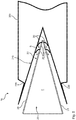
Fig. 3 ist schematisch eine erste Ausführungsform einer erfindungsgemäßen Kühlvorrichtung 10 dargestellt. Ein Kühlkanal 20 wird ausgebildet und nach außen abgeschlossen durch zwei Austrittsflächen 24, welche spitzwinklig zueinander ausgebildet sind. Im Kühlabschnitt 22 des Kühlkanals 20 sind Austrittsöffnungen 26 angeordnet, durch welche das Kühlfluid F austreten kann. Um zu vermeiden, dass das Kühlfluid F eine Strömungsrichtung senkrecht auf die benachbarte Seitenfalte 210 aufweist, ist hier ein abgekantetes Blech als Leitelement 30 vorgesehen, welches eine Umlenkung der Strömungsrichtung S im Wesentlichen entlang oder sogar parallel zu den Austrittsflächen 24 ermöglicht. Hier ist auch gut eine Korrelation zur Transportrichtung T zu erkennen, sodass die Ausrichtung der Strömungsrichtung S auch quer bzw. sogar senkrecht zur Transportrichtung T erfolgt. -
Fig. 4 zeigt eine Variante, bei welcher die Austrittsöffnungen 26 direkt im Scheitelbereich 28, bevorzugt im Scheitel 28a zwischen den Austrittsflächen 24 angeordnet sind. Damit kann die geometrische Erstreckung des Leitelements 30 deutlich reduziert werden im Vergleich zur Ausführungsform derFig. 3 . Auch erfolgt die Einbringung des Kühlfluids F an der tiefsten Stelle innerhalb der Seitenfalte 210, sodass die Kühlwirkung vorzugsweise ideal erreicht wird. -
Fig. 5 zeigt eine weitere Ausführungsform einer erfindungsgemäßen Kühlvorrichtung 10, welche hier in Korrelation mit dem Folienmaterial 200 dargestellt ist. Hier ist gut zu erkennen, dass sich die Flächen der Seitenfalte 210 im Wesentlichen parallel entlang der Austrittsflächen 24 anordnen. Die Strömungsrichtung S, welche spitzwinklig, vorzugsweise parallel, zu den Austrittsflächen 24 ausgerichtet ist, weist dementsprechend eine ähnliche oder sogar gleiche Ausrichtung auch zu den Flächen der Seitenfalte 210 auf. Bei der Ausführungsform derFig. 5 ist eine Vielzahl von Leitelementen 30 für jede Austrittsöffnung 26 einzeln vorgesehen. Dementsprechend wird eine noch gezieltere Beeinflussung der Strömungsrichtung S beim Austritt des Kühlfluids F möglich. - Die voranstehende Erläuterung der Ausführungsformen beschreibt die vorliegende Erfindung ausschließlich im Rahmen von Beispielen.
-
- 10
- Kühlvorrichtung
- 20
- Kühlkanal
- 22
- Kühlabschnitt
- 24
- Austrittsfläche
- 26
- Austrittsöffnung
- 28
- Scheitelbereich
- 28a
- Scheitel
- 30
- Leitelement
- 100
- Sackfüllanlage
- 110
- Siegelstation
- 170
- Station
- 200
- Folienmaterial
- 210
- Seitenfalte
- 220
- Schweißnaht
- F
- Kühlfluid
- T
- Transportrichtung
- S
- Strömungsrichtung
Claims (10)
- Kühlvorrichtung (10) für die Kühlung einer Schweißnaht (220) an einer Seitenfalte (210) eines Folienmaterials (200) in einer Sackfüllanlage (100), aufweisend einen Kühlkanal (20) für die Zufuhr von Kühlfluid (F), wobei der Kühlkanal (20) einen Kühlabschnitt (22) mit zwei spitzwinklig zueinander ausgerichteten Austrittsflächen (24) aufweist, in welchen Austrittsöffnungen (26) für den Austritt des Kühlfluids (F) aus dem Kühlkanal (20) ausgebildet sind, dadurch gekennzeichnet, dass der Kühlabschnitt (22) zumindest ein Leitelement (30) für das Leiten des Kühlfluids (F) aufweist, wobei das zumindest eine Leitelement (30) die Strömungsrichtung (S) des aus den Austrittsöffnungen (26) ausgetretenen Kühlfluids (F) spitzwinklig zu der jeweiligen Austrittsfläche (24) ausrichtet.
- Kühlvorrichtung (10) nach Anspruch 1, dadurch gekennzeichnet, dass der Austrittswinkel zwischen der Strömungsrichtung (S) des aus den Austrittsöffnungen (26) ausgetretenen Kühlfluids (F) und den Austrittsflächen (24) kleiner oder gleich ca. 45° beträgt.
- Kühlvorrichtung (10) nach einem der vorangegangenen Ansprüche, dadurch gekennzeichnet, dass die Strömungsrichtung (S) des aus den Austrittsöffnungen (26) ausgetretenen Kühlfluids (F) entlang der Austrittsflächen (24), insbesondere parallel oder im Wesentlichen parallel zu den Austrittsflächen (24), ausgerichtet ist.
- Kühlvorrichtung (10) nach einem der vorangegangenen Ansprüche, dadurch gekennzeichnet, dass die Austrittsöffnungen (26) im Scheitelbereich (28) der Austrittsflächen (24), insbesondere genau am Scheitel (28a) der Austrittsflächen (24), angeordnet sind.
- Kühlvorrichtung (10) nach einem der vorangegangenen Ansprüche, dadurch gekennzeichnet, dass das wenigstens eine Leitelement (30) austauschbar an dem Kühlkanal (20) befestigt ist.
- Kühlvorrichtung (10) nach einem der vorangegangenen Ansprüche, dadurch gekennzeichnet, dass die Austrittsöffnungen (26) einen freien Öffnungsquerschnitt aufweisen, welcher eine Beschleunigung der Strömung des Kühlfluids (F) erzeugt.
- Kühlvorrichtung (10) nach einem der vorangegangenen Ansprüche, dadurch gekennzeichnet, dass die Länge des wenigstens einen Leitelements (30) in Transportrichtung (T) des Folienmaterials (200) kleiner oder gleich der Länge der Schweißnaht (220) in Transportrichtung (T) des Folienmaterials (200) ist.
- Kühlvorrichtung (10) nach einem der vorangegangenen Ansprüche, dadurch gekennzeichnet, dass die Strömungsrichtung (S) des aus den Austrittsöffnungen (24) ausgetretenen Kühlfluids (F) quer oder im Wesentlichen quer zur Transportrichtung (T) des Folienmaterials (200) ausgerichtet ist.
- Sackfüllanlage (100) für die Befüllung von Säcken mit einem Schüttgut, aufweisend eine Siegelstation (110) für das Erzeugen zumindest einer Schweißnaht (220) in einer Seitenfalte (210) eines Folienmaterials (200), insbesondere in Form einer Folienbahn, weiter aufweisend eine Kühlvorrichtung (10) für das Kühlen der erzeugten Schweißnaht (220), dadurch gekennzeichnet, dass die Kühlvorrichtung (10) die Merkmale eines der Ansprüche 1 bis 8 aufweist.
- Sackfüllanlage (100) nach Anspruch 9, dadurch gekennzeichnet, dass die Kühlvorrichtung (10), insbesondere der Kühlkanal (20) entlang oder im Wesentlichen entlang der Transportrichtung (T) des Folienmaterials (200) ausgerichtet ist.
Applications Claiming Priority (2)
| Application Number | Priority Date | Filing Date | Title |
|---|---|---|---|
| DE201310105549 DE102013105549B3 (de) | 2013-05-29 | 2013-05-29 | Kühlvorrichtung für die Kühlung einer Schweißnaht an einer Seitenfalte eines Folienmaterials in einer Sackfüllanlage |
| PCT/EP2014/058902 WO2014191151A1 (de) | 2013-05-29 | 2014-04-30 | KÜHLVORRICHTUNG FÜR DIE KÜHLUNG EINER SCHWEIßNAHT AN EINER SEITENFALTE EINES FOLIENMATERIALS IN EINER SACKFÜLLANLAGE |
Publications (2)
| Publication Number | Publication Date |
|---|---|
| EP3003687A1 EP3003687A1 (de) | 2016-04-13 |
| EP3003687B1 true EP3003687B1 (de) | 2019-02-20 |
Family
ID=50736050
Family Applications (1)
| Application Number | Title | Priority Date | Filing Date |
|---|---|---|---|
| EP14725027.8A Not-in-force EP3003687B1 (de) | 2013-05-29 | 2014-04-30 | Kühlvorrichtung für die kühlung einer schweissnaht an einer seitenfalte eines folienmaterials in einer sackfüllanlage |
Country Status (4)
| Country | Link |
|---|---|
| EP (1) | EP3003687B1 (de) |
| DE (1) | DE102013105549B3 (de) |
| ES (1) | ES2715711T3 (de) |
| WO (1) | WO2014191151A1 (de) |
Families Citing this family (3)
| Publication number | Priority date | Publication date | Assignee | Title |
|---|---|---|---|---|
| DE202016008986U1 (de) | 2016-11-22 | 2021-06-10 | Payper S.A. | Kühlvorrichtung zum Kühlen von Verschlüssen in einer Folie in einer Form-, Füll- und Verschlussmaschine |
| EP3323741A1 (de) | 2016-11-22 | 2018-05-23 | Payper, S.A. | Kühlvorrichtung zum kühlen von abdichtungen in einer folie in einer form-füll-siegelmaschine |
| AT525719B1 (de) * | 2019-08-01 | 2023-10-15 | Tecn Mecanicas Ilerdenses S L | Formstation zum Formen von Säcken unterschiedlicher Kapazität aus einem flachen Schlauchmaterial und entsprechende Maschine |
Family Cites Families (9)
| Publication number | Priority date | Publication date | Assignee | Title |
|---|---|---|---|---|
| DE1586248A1 (de) * | 1967-06-22 | 1970-10-22 | Rovema Verpackungsmaschinen | Verfahren und Vorrichtung von verschweissten grossraeumigen Kunststoffsaecken fuer Verpackungsmaschinen |
| DE2415228C2 (de) * | 1973-04-04 | 1985-10-31 | The Dow Chemical Co., Midland, Mich. | Vorrichtung zum Herstellen und Füllen von Säcken aus thermisch verschweißbarem Material |
| DE3937772A1 (de) * | 1988-11-17 | 1990-05-23 | Barmag Barmer Maschf | Vorrichtung zum einlegen von seitenfalten in kunststoffschlauchfolie |
| DE19507445A1 (de) * | 1995-03-03 | 1996-09-05 | Rovema Gmbh | Schlauchbeutelmaschine mit einem Seitenfaltenerzeuger, Verfahren zur Schlauchbeutelerzeugung und Schlauchbeutel mit einer Seitenfalte |
| DE19603371B4 (de) * | 1996-01-31 | 2006-12-14 | Rovema - Verpackungsmaschinen Gmbh | Schlauchbeutelmaschine mit einer asymmetrischen Formschulter zur Herstellung von Schlauchbeuteln |
| DE29624455U1 (de) * | 1996-01-31 | 2003-12-18 | Rovema - Verpackungsmaschinen Gmbh | Schlauchbeutelmaschine mit einer asymmetrischen Formschulter zur Herstellung von Schlauchbeuteln |
| DE69701180T2 (de) * | 1996-05-08 | 2000-09-14 | Payper S.A., Lleida | Selbständig arbeitende aufsackmaschine |
| DE102004034489A1 (de) * | 2004-07-16 | 2006-04-20 | Windmöller & Hölscher Kg | Verfahren und Vorrichtung zur Herstellung und Befüllung von Säcken |
| EP1923202B1 (de) * | 2006-11-17 | 2009-01-21 | Teepack Spezialmaschinen Gmbh & Co. Kg | Verfahren und Vorrichtung zum Herstellen eines Schlauchbeutels |
-
2013
- 2013-05-29 DE DE201310105549 patent/DE102013105549B3/de not_active Expired - Fee Related
-
2014
- 2014-04-30 EP EP14725027.8A patent/EP3003687B1/de not_active Not-in-force
- 2014-04-30 WO PCT/EP2014/058902 patent/WO2014191151A1/de not_active Ceased
- 2014-04-30 ES ES14725027T patent/ES2715711T3/es active Active
Non-Patent Citations (1)
| Title |
|---|
| None * |
Also Published As
| Publication number | Publication date |
|---|---|
| WO2014191151A1 (de) | 2014-12-04 |
| EP3003687A1 (de) | 2016-04-13 |
| DE102013105549B3 (de) | 2014-07-03 |
| ES2715711T3 (es) | 2019-06-05 |
Similar Documents
| Publication | Publication Date | Title |
|---|---|---|
| EP1514810B1 (de) | Kunststoffschlauch zur Herstellung gasgefüllter Füllkörper sowie Vorrichtung zur Befüllung | |
| DE10032551B4 (de) | Formschulter und Vorrichtung zur Herstellung von längsgeformten Bahnen | |
| EP1462364B2 (de) | Schlauchbeutelmaschine | |
| EP2301849B1 (de) | Schlauchbeutelmaschine zum Herstellen und Füllen von schlauchartigen Beuteln | |
| DE3401959A1 (de) | Vorrichtung zum abdichten von hohlkoerpern | |
| EP2763906B1 (de) | Entlüftbarer verpackungsbehälter | |
| EP1981768A1 (de) | Sack und verfahren zur herstellung desselben | |
| DE3905605A1 (de) | Verfahren und vorrichtung zum herstellen, fuellen und verschliessen von beuteln | |
| DE102013105549B3 (de) | Kühlvorrichtung für die Kühlung einer Schweißnaht an einer Seitenfalte eines Folienmaterials in einer Sackfüllanlage | |
| EP2387495B1 (de) | VORRICHTUNG ZUM SCHWEIßEN UND TRENNEN VON PACKSTOFFEN | |
| EP2015997B1 (de) | FÜLLMASCHINE FÜR OFFENE, SCHWEIßBARE SÄCKE | |
| DE10160408C2 (de) | Gasgefüllte Füllkörper | |
| DE102012109890B4 (de) | Automatische Dehnungspuffereinrichtung | |
| WO2018060277A1 (de) | Kunststoffsack, insbesondere ffs-sack, sowie verfahren und vorrichtung zur herstellung und zum befüllen eines sacks | |
| EP2480458A1 (de) | Formschulter und vorrichtung zum herstellen von schlauchbeuteln | |
| DE102014101802B4 (de) | Verfahren und Vorrichtung zum Ultraschall-Siegeln und Trennen von Schlauchbeuteln | |
| DE102013100131A1 (de) | Verfahren zum Herstellen von Säcken | |
| EP3826831B1 (de) | Vorrichtung und verfahren zur herstellung wenigstens eines leeren offenen sackes | |
| EP2601103B1 (de) | Vorrichtung zur herstellung einer verpackung | |
| EP3328739B1 (de) | Verfahren zum betrieb einer schlauchbeutelmaschine zur herstellung von beuteln mit einer boden-quernaht und einer davon unterschiedlichen kopf-quernaht | |
| DE102011004297B3 (de) | Mehrteilige Formschulter | |
| DE10304913B4 (de) | Vorrichtung zum Aufnehmen eines Folienschlauches und vertikale Schlauchbeutelmaschine mit einer derartigen Vorrichtung | |
| DE10307678A1 (de) | Schlauch sowie Vorrichtung und Verfahren zur Herstellung desselben | |
| DE102012112918A1 (de) | Schlauchbeutelmaschine | |
| DE10330294A1 (de) | Vertikale Schlauchbeutelmaschine |
Legal Events
| Date | Code | Title | Description |
|---|---|---|---|
| PUAI | Public reference made under article 153(3) epc to a published international application that has entered the european phase |
Free format text: ORIGINAL CODE: 0009012 |
|
| 17P | Request for examination filed |
Effective date: 20160104 |
|
| AK | Designated contracting states |
Kind code of ref document: A1 Designated state(s): AL AT BE BG CH CY CZ DE DK EE ES FI FR GB GR HR HU IE IS IT LI LT LU LV MC MK MT NL NO PL PT RO RS SE SI SK SM TR |
|
| AX | Request for extension of the european patent |
Extension state: BA ME |
|
| RIN1 | Information on inventor provided before grant (corrected) |
Inventor name: HUIL, OLIVER Inventor name: UDALLY, RALF Inventor name: VOSS, HANS-LUDWIG |
|
| DAX | Request for extension of the european patent (deleted) | ||
| RIC1 | Information provided on ipc code assigned before grant |
Ipc: B29C 35/16 20060101ALI20180912BHEP Ipc: B31B 70/26 20170101ALI20180912BHEP Ipc: B65B 51/32 20060101ALI20180912BHEP Ipc: B29C 65/02 20060101AFI20180912BHEP |
|
| GRAP | Despatch of communication of intention to grant a patent |
Free format text: ORIGINAL CODE: EPIDOSNIGR1 |
|
| STAA | Information on the status of an ep patent application or granted ep patent |
Free format text: STATUS: GRANT OF PATENT IS INTENDED |
|
| INTG | Intention to grant announced |
Effective date: 20181102 |
|
| GRAS | Grant fee paid |
Free format text: ORIGINAL CODE: EPIDOSNIGR3 |
|
| GRAA | (expected) grant |
Free format text: ORIGINAL CODE: 0009210 |
|
| STAA | Information on the status of an ep patent application or granted ep patent |
Free format text: STATUS: THE PATENT HAS BEEN GRANTED |
|
| RIC1 | Information provided on ipc code assigned before grant |
Ipc: B31B 70/26 20170101ALI20180912BHEP Ipc: B29C 35/16 20060101ALI20180912BHEP Ipc: B29C 65/02 20060101AFI20180912BHEP Ipc: B65B 51/32 20060101ALI20180912BHEP |
|
| AK | Designated contracting states |
Kind code of ref document: B1 Designated state(s): AL AT BE BG CH CY CZ DE DK EE ES FI FR GB GR HR HU IE IS IT LI LT LU LV MC MK MT NL NO PL PT RO RS SE SI SK SM TR |
|
| REG | Reference to a national code |
Ref country code: GB Ref legal event code: FG4D Free format text: NOT ENGLISH |
|
| REG | Reference to a national code |
Ref country code: CH Ref legal event code: EP |
|
| REG | Reference to a national code |
Ref country code: DE Ref legal event code: R096 Ref document number: 502014010860 Country of ref document: DE |
|
| REG | Reference to a national code |
Ref country code: AT Ref legal event code: REF Ref document number: 1097624 Country of ref document: AT Kind code of ref document: T Effective date: 20190315 |
|
| REG | Reference to a national code |
Ref country code: IE Ref legal event code: FG4D Free format text: LANGUAGE OF EP DOCUMENT: GERMAN |
|
| REG | Reference to a national code |
Ref country code: ES Ref legal event code: FG2A Ref document number: 2715711 Country of ref document: ES Kind code of ref document: T3 Effective date: 20190605 |
|
| REG | Reference to a national code |
Ref country code: NL Ref legal event code: MP Effective date: 20190220 |
|
| REG | Reference to a national code |
Ref country code: LT Ref legal event code: MG4D |
|
| PG25 | Lapsed in a contracting state [announced via postgrant information from national office to epo] |
Ref country code: NO Free format text: LAPSE BECAUSE OF FAILURE TO SUBMIT A TRANSLATION OF THE DESCRIPTION OR TO PAY THE FEE WITHIN THE PRESCRIBED TIME-LIMIT Effective date: 20190520 Ref country code: SE Free format text: LAPSE BECAUSE OF FAILURE TO SUBMIT A TRANSLATION OF THE DESCRIPTION OR TO PAY THE FEE WITHIN THE PRESCRIBED TIME-LIMIT Effective date: 20190220 Ref country code: FI Free format text: LAPSE BECAUSE OF FAILURE TO SUBMIT A TRANSLATION OF THE DESCRIPTION OR TO PAY THE FEE WITHIN THE PRESCRIBED TIME-LIMIT Effective date: 20190220 Ref country code: PT Free format text: LAPSE BECAUSE OF FAILURE TO SUBMIT A TRANSLATION OF THE DESCRIPTION OR TO PAY THE FEE WITHIN THE PRESCRIBED TIME-LIMIT Effective date: 20190620 Ref country code: NL Free format text: LAPSE BECAUSE OF FAILURE TO SUBMIT A TRANSLATION OF THE DESCRIPTION OR TO PAY THE FEE WITHIN THE PRESCRIBED TIME-LIMIT Effective date: 20190220 Ref country code: LT Free format text: LAPSE BECAUSE OF FAILURE TO SUBMIT A TRANSLATION OF THE DESCRIPTION OR TO PAY THE FEE WITHIN THE PRESCRIBED TIME-LIMIT Effective date: 20190220 |
|
| PG25 | Lapsed in a contracting state [announced via postgrant information from national office to epo] |
Ref country code: LV Free format text: LAPSE BECAUSE OF FAILURE TO SUBMIT A TRANSLATION OF THE DESCRIPTION OR TO PAY THE FEE WITHIN THE PRESCRIBED TIME-LIMIT Effective date: 20190220 Ref country code: HR Free format text: LAPSE BECAUSE OF FAILURE TO SUBMIT A TRANSLATION OF THE DESCRIPTION OR TO PAY THE FEE WITHIN THE PRESCRIBED TIME-LIMIT Effective date: 20190220 Ref country code: BG Free format text: LAPSE BECAUSE OF FAILURE TO SUBMIT A TRANSLATION OF THE DESCRIPTION OR TO PAY THE FEE WITHIN THE PRESCRIBED TIME-LIMIT Effective date: 20190520 Ref country code: IS Free format text: LAPSE BECAUSE OF FAILURE TO SUBMIT A TRANSLATION OF THE DESCRIPTION OR TO PAY THE FEE WITHIN THE PRESCRIBED TIME-LIMIT Effective date: 20190620 Ref country code: GR Free format text: LAPSE BECAUSE OF FAILURE TO SUBMIT A TRANSLATION OF THE DESCRIPTION OR TO PAY THE FEE WITHIN THE PRESCRIBED TIME-LIMIT Effective date: 20190521 Ref country code: RS Free format text: LAPSE BECAUSE OF FAILURE TO SUBMIT A TRANSLATION OF THE DESCRIPTION OR TO PAY THE FEE WITHIN THE PRESCRIBED TIME-LIMIT Effective date: 20190220 |
|
| PG25 | Lapsed in a contracting state [announced via postgrant information from national office to epo] |
Ref country code: DK Free format text: LAPSE BECAUSE OF FAILURE TO SUBMIT A TRANSLATION OF THE DESCRIPTION OR TO PAY THE FEE WITHIN THE PRESCRIBED TIME-LIMIT Effective date: 20190220 Ref country code: EE Free format text: LAPSE BECAUSE OF FAILURE TO SUBMIT A TRANSLATION OF THE DESCRIPTION OR TO PAY THE FEE WITHIN THE PRESCRIBED TIME-LIMIT Effective date: 20190220 Ref country code: SK Free format text: LAPSE BECAUSE OF FAILURE TO SUBMIT A TRANSLATION OF THE DESCRIPTION OR TO PAY THE FEE WITHIN THE PRESCRIBED TIME-LIMIT Effective date: 20190220 Ref country code: RO Free format text: LAPSE BECAUSE OF FAILURE TO SUBMIT A TRANSLATION OF THE DESCRIPTION OR TO PAY THE FEE WITHIN THE PRESCRIBED TIME-LIMIT Effective date: 20190220 Ref country code: CZ Free format text: LAPSE BECAUSE OF FAILURE TO SUBMIT A TRANSLATION OF THE DESCRIPTION OR TO PAY THE FEE WITHIN THE PRESCRIBED TIME-LIMIT Effective date: 20190220 Ref country code: AL Free format text: LAPSE BECAUSE OF FAILURE TO SUBMIT A TRANSLATION OF THE DESCRIPTION OR TO PAY THE FEE WITHIN THE PRESCRIBED TIME-LIMIT Effective date: 20190220 |
|
| REG | Reference to a national code |
Ref country code: DE Ref legal event code: R097 Ref document number: 502014010860 Country of ref document: DE |
|
| PG25 | Lapsed in a contracting state [announced via postgrant information from national office to epo] |
Ref country code: SM Free format text: LAPSE BECAUSE OF FAILURE TO SUBMIT A TRANSLATION OF THE DESCRIPTION OR TO PAY THE FEE WITHIN THE PRESCRIBED TIME-LIMIT Effective date: 20190220 Ref country code: PL Free format text: LAPSE BECAUSE OF FAILURE TO SUBMIT A TRANSLATION OF THE DESCRIPTION OR TO PAY THE FEE WITHIN THE PRESCRIBED TIME-LIMIT Effective date: 20190220 |
|
| REG | Reference to a national code |
Ref country code: CH Ref legal event code: PL |
|
| REG | Reference to a national code |
Ref country code: BE Ref legal event code: MM Effective date: 20190430 |
|
| PLBE | No opposition filed within time limit |
Free format text: ORIGINAL CODE: 0009261 |
|
| STAA | Information on the status of an ep patent application or granted ep patent |
Free format text: STATUS: NO OPPOSITION FILED WITHIN TIME LIMIT |
|
| PG25 | Lapsed in a contracting state [announced via postgrant information from national office to epo] |
Ref country code: MC Free format text: LAPSE BECAUSE OF FAILURE TO SUBMIT A TRANSLATION OF THE DESCRIPTION OR TO PAY THE FEE WITHIN THE PRESCRIBED TIME-LIMIT Effective date: 20190220 Ref country code: LU Free format text: LAPSE BECAUSE OF NON-PAYMENT OF DUE FEES Effective date: 20190430 |
|
| 26N | No opposition filed |
Effective date: 20191121 |
|
| GBPC | Gb: european patent ceased through non-payment of renewal fee |
Effective date: 20190520 |
|
| PG25 | Lapsed in a contracting state [announced via postgrant information from national office to epo] |
Ref country code: LI Free format text: LAPSE BECAUSE OF NON-PAYMENT OF DUE FEES Effective date: 20190430 Ref country code: CH Free format text: LAPSE BECAUSE OF NON-PAYMENT OF DUE FEES Effective date: 20190430 |
|
| PG25 | Lapsed in a contracting state [announced via postgrant information from national office to epo] |
Ref country code: BE Free format text: LAPSE BECAUSE OF NON-PAYMENT OF DUE FEES Effective date: 20190430 Ref country code: FR Free format text: LAPSE BECAUSE OF NON-PAYMENT OF DUE FEES Effective date: 20190430 Ref country code: SI Free format text: LAPSE BECAUSE OF FAILURE TO SUBMIT A TRANSLATION OF THE DESCRIPTION OR TO PAY THE FEE WITHIN THE PRESCRIBED TIME-LIMIT Effective date: 20190220 |
|
| PG25 | Lapsed in a contracting state [announced via postgrant information from national office to epo] |
Ref country code: TR Free format text: LAPSE BECAUSE OF FAILURE TO SUBMIT A TRANSLATION OF THE DESCRIPTION OR TO PAY THE FEE WITHIN THE PRESCRIBED TIME-LIMIT Effective date: 20190220 |
|
| PG25 | Lapsed in a contracting state [announced via postgrant information from national office to epo] |
Ref country code: IE Free format text: LAPSE BECAUSE OF NON-PAYMENT OF DUE FEES Effective date: 20190430 Ref country code: GB Free format text: LAPSE BECAUSE OF NON-PAYMENT OF DUE FEES Effective date: 20190520 |
|
| PG25 | Lapsed in a contracting state [announced via postgrant information from national office to epo] |
Ref country code: CY Free format text: LAPSE BECAUSE OF FAILURE TO SUBMIT A TRANSLATION OF THE DESCRIPTION OR TO PAY THE FEE WITHIN THE PRESCRIBED TIME-LIMIT Effective date: 20190220 |
|
| PG25 | Lapsed in a contracting state [announced via postgrant information from national office to epo] |
Ref country code: MT Free format text: LAPSE BECAUSE OF FAILURE TO SUBMIT A TRANSLATION OF THE DESCRIPTION OR TO PAY THE FEE WITHIN THE PRESCRIBED TIME-LIMIT Effective date: 20190220 Ref country code: HU Free format text: LAPSE BECAUSE OF FAILURE TO SUBMIT A TRANSLATION OF THE DESCRIPTION OR TO PAY THE FEE WITHIN THE PRESCRIBED TIME-LIMIT; INVALID AB INITIO Effective date: 20140430 |
|
| PG25 | Lapsed in a contracting state [announced via postgrant information from national office to epo] |
Ref country code: MK Free format text: LAPSE BECAUSE OF FAILURE TO SUBMIT A TRANSLATION OF THE DESCRIPTION OR TO PAY THE FEE WITHIN THE PRESCRIBED TIME-LIMIT Effective date: 20190220 |
|
| PGFP | Annual fee paid to national office [announced via postgrant information from national office to epo] |
Ref country code: IT Payment date: 20230421 Year of fee payment: 10 Ref country code: ES Payment date: 20230515 Year of fee payment: 10 Ref country code: DE Payment date: 20230430 Year of fee payment: 10 |
|
| PGFP | Annual fee paid to national office [announced via postgrant information from national office to epo] |
Ref country code: AT Payment date: 20230419 Year of fee payment: 10 |
|
| REG | Reference to a national code |
Ref country code: DE Ref legal event code: R119 Ref document number: 502014010860 Country of ref document: DE |
|
| REG | Reference to a national code |
Ref country code: AT Ref legal event code: MM01 Ref document number: 1097624 Country of ref document: AT Kind code of ref document: T Effective date: 20240430 |
|
| PG25 | Lapsed in a contracting state [announced via postgrant information from national office to epo] |
Ref country code: DE Free format text: LAPSE BECAUSE OF NON-PAYMENT OF DUE FEES Effective date: 20241105 |
|
| PG25 | Lapsed in a contracting state [announced via postgrant information from national office to epo] |
Ref country code: AT Free format text: LAPSE BECAUSE OF NON-PAYMENT OF DUE FEES Effective date: 20240430 |
|
| PG25 | Lapsed in a contracting state [announced via postgrant information from national office to epo] |
Ref country code: DE Free format text: LAPSE BECAUSE OF NON-PAYMENT OF DUE FEES Effective date: 20241105 Ref country code: AT Free format text: LAPSE BECAUSE OF NON-PAYMENT OF DUE FEES Effective date: 20240430 |
|
| PG25 | Lapsed in a contracting state [announced via postgrant information from national office to epo] |
Ref country code: IT Free format text: LAPSE BECAUSE OF NON-PAYMENT OF DUE FEES Effective date: 20240430 |
|
| REG | Reference to a national code |
Ref country code: ES Ref legal event code: FD2A Effective date: 20250605 |
|
| PG25 | Lapsed in a contracting state [announced via postgrant information from national office to epo] |
Ref country code: ES Free format text: LAPSE BECAUSE OF NON-PAYMENT OF DUE FEES Effective date: 20240501 |