EP3003118B1 - Positionsschätzung einer bildgebungskapsel im verdauungstrakt - Google Patents
Positionsschätzung einer bildgebungskapsel im verdauungstrakt Download PDFInfo
- Publication number
- EP3003118B1 EP3003118B1 EP14807239.0A EP14807239A EP3003118B1 EP 3003118 B1 EP3003118 B1 EP 3003118B1 EP 14807239 A EP14807239 A EP 14807239A EP 3003118 B1 EP3003118 B1 EP 3003118B1
- Authority
- EP
- European Patent Office
- Prior art keywords
- recorder
- imaging capsule
- coil
- capsule
- accelerometer
- Prior art date
- Legal status (The legal status is an assumption and is not a legal conclusion. Google has not performed a legal analysis and makes no representation as to the accuracy of the status listed.)
- Active
Links
Images


Classifications
-
- A—HUMAN NECESSITIES
- A61—MEDICAL OR VETERINARY SCIENCE; HYGIENE
- A61B—DIAGNOSIS; SURGERY; IDENTIFICATION
- A61B5/00—Measuring for diagnostic purposes; Identification of persons
- A61B5/06—Devices, other than using radiation, for detecting or locating foreign bodies ; Determining position of diagnostic devices within or on the body of the patient
- A61B5/061—Determining position of a probe within the body employing means separate from the probe, e.g. sensing internal probe position employing impedance electrodes on the surface of the body
- A61B5/062—Determining position of a probe within the body employing means separate from the probe, e.g. sensing internal probe position employing impedance electrodes on the surface of the body using magnetic field
-
- A—HUMAN NECESSITIES
- A61—MEDICAL OR VETERINARY SCIENCE; HYGIENE
- A61B—DIAGNOSIS; SURGERY; IDENTIFICATION
- A61B1/00—Instruments for performing medical examinations of the interior of cavities or tubes of the body by visual or photographical inspection, e.g. endoscopes; Illuminating arrangements therefor
- A61B1/00002—Operational features of endoscopes
- A61B1/00004—Operational features of endoscopes characterised by electronic signal processing
-
- A—HUMAN NECESSITIES
- A61—MEDICAL OR VETERINARY SCIENCE; HYGIENE
- A61B—DIAGNOSIS; SURGERY; IDENTIFICATION
- A61B1/00—Instruments for performing medical examinations of the interior of cavities or tubes of the body by visual or photographical inspection, e.g. endoscopes; Illuminating arrangements therefor
- A61B1/00002—Operational features of endoscopes
- A61B1/00011—Operational features of endoscopes characterised by signal transmission
- A61B1/00016—Operational features of endoscopes characterised by signal transmission using wireless means
-
- A—HUMAN NECESSITIES
- A61—MEDICAL OR VETERINARY SCIENCE; HYGIENE
- A61B—DIAGNOSIS; SURGERY; IDENTIFICATION
- A61B1/00—Instruments for performing medical examinations of the interior of cavities or tubes of the body by visual or photographical inspection, e.g. endoscopes; Illuminating arrangements therefor
- A61B1/00002—Operational features of endoscopes
- A61B1/0002—Operational features of endoscopes provided with data storages
-
- A—HUMAN NECESSITIES
- A61—MEDICAL OR VETERINARY SCIENCE; HYGIENE
- A61B—DIAGNOSIS; SURGERY; IDENTIFICATION
- A61B1/00—Instruments for performing medical examinations of the interior of cavities or tubes of the body by visual or photographical inspection, e.g. endoscopes; Illuminating arrangements therefor
- A61B1/04—Instruments for performing medical examinations of the interior of cavities or tubes of the body by visual or photographical inspection, e.g. endoscopes; Illuminating arrangements therefor combined with photographic or television appliances
- A61B1/041—Capsule endoscopes for imaging
-
- A—HUMAN NECESSITIES
- A61—MEDICAL OR VETERINARY SCIENCE; HYGIENE
- A61B—DIAGNOSIS; SURGERY; IDENTIFICATION
- A61B1/00—Instruments for performing medical examinations of the interior of cavities or tubes of the body by visual or photographical inspection, e.g. endoscopes; Illuminating arrangements therefor
- A61B1/04—Instruments for performing medical examinations of the interior of cavities or tubes of the body by visual or photographical inspection, e.g. endoscopes; Illuminating arrangements therefor combined with photographic or television appliances
- A61B1/045—Control thereof
-
- A—HUMAN NECESSITIES
- A61—MEDICAL OR VETERINARY SCIENCE; HYGIENE
- A61B—DIAGNOSIS; SURGERY; IDENTIFICATION
- A61B5/00—Measuring for diagnostic purposes; Identification of persons
-
- A—HUMAN NECESSITIES
- A61—MEDICAL OR VETERINARY SCIENCE; HYGIENE
- A61B—DIAGNOSIS; SURGERY; IDENTIFICATION
- A61B5/00—Measuring for diagnostic purposes; Identification of persons
- A61B5/07—Endoradiosondes
- A61B5/073—Intestinal transmitters
-
- A—HUMAN NECESSITIES
- A61—MEDICAL OR VETERINARY SCIENCE; HYGIENE
- A61B—DIAGNOSIS; SURGERY; IDENTIFICATION
- A61B5/00—Measuring for diagnostic purposes; Identification of persons
- A61B5/68—Arrangements of detecting, measuring or recording means, e.g. sensors, in relation to patient
- A61B5/6801—Arrangements of detecting, measuring or recording means, e.g. sensors, in relation to patient specially adapted to be attached to or worn on the body surface
- A61B5/683—Means for maintaining contact with the body
- A61B5/6832—Means for maintaining contact with the body using adhesives
- A61B5/6833—Adhesive patches
-
- A—HUMAN NECESSITIES
- A61—MEDICAL OR VETERINARY SCIENCE; HYGIENE
- A61B—DIAGNOSIS; SURGERY; IDENTIFICATION
- A61B5/00—Measuring for diagnostic purposes; Identification of persons
- A61B5/72—Signal processing specially adapted for physiological signals or for diagnostic purposes
- A61B5/7203—Signal processing specially adapted for physiological signals or for diagnostic purposes for noise prevention, reduction or removal
-
- A—HUMAN NECESSITIES
- A61—MEDICAL OR VETERINARY SCIENCE; HYGIENE
- A61B—DIAGNOSIS; SURGERY; IDENTIFICATION
- A61B5/00—Measuring for diagnostic purposes; Identification of persons
- A61B5/72—Signal processing specially adapted for physiological signals or for diagnostic purposes
- A61B5/7235—Details of waveform analysis
- A61B5/725—Details of waveform analysis using specific filters therefor, e.g. Kalman or adaptive filters
-
- A—HUMAN NECESSITIES
- A61—MEDICAL OR VETERINARY SCIENCE; HYGIENE
- A61B—DIAGNOSIS; SURGERY; IDENTIFICATION
- A61B2562/00—Details of sensors; Constructional details of sensor housings or probes; Accessories for sensors
- A61B2562/02—Details of sensors specially adapted for in-vivo measurements
- A61B2562/0219—Inertial sensors, e.g. accelerometers, gyroscopes, tilt switches
-
- A—HUMAN NECESSITIES
- A61—MEDICAL OR VETERINARY SCIENCE; HYGIENE
- A61B—DIAGNOSIS; SURGERY; IDENTIFICATION
- A61B2562/00—Details of sensors; Constructional details of sensor housings or probes; Accessories for sensors
- A61B2562/02—Details of sensors specially adapted for in-vivo measurements
- A61B2562/0223—Magnetic field sensors
-
- A—HUMAN NECESSITIES
- A61—MEDICAL OR VETERINARY SCIENCE; HYGIENE
- A61B—DIAGNOSIS; SURGERY; IDENTIFICATION
- A61B2562/00—Details of sensors; Constructional details of sensor housings or probes; Accessories for sensors
- A61B2562/16—Details of sensor housings or probes; Details of structural supports for sensors
- A61B2562/162—Capsule shaped sensor housings, e.g. for swallowing or implantation
Definitions
- the present disclosure relates generally to investigating the insides of a patient's colon using an intra-lumen imaging capsule and more specifically to estimating the position of the capsule as it traverses the gastrointestinal tract.
- One method for examining the gastrointestinal tract for the existence of polyps and other clinically relevant features that may provide an indication regarding the potential of cancer is performed by swallowing an imaging capsule that will travel through the gastrointestinal (GI) tract and viewing the patient's situation internally. In a typical case the trip can take between 24-48 hours, after which the imaging capsule exits in the patient's feces.
- the patient swallows a contrast agent to enhance the imaging ability of the imaging capsule. Then the patient swallows the imaging capsule to examine the gastrointestinal tract while flowing through the contrast agent.
- the imaging capsule typically includes a radiation source, for example including a radioisotope that emits X-rays or Gamma rays.
- the radiation is typically collimated to allow it to be controllably directed in a specific direction during the imaging process.
- the imaging capsule is designed to measure Compton back-scattering and/or X-ray florescence and wirelessly transmit the measurements (e.g. a count rate) to an external analysis device, for example a computer or other dedicated instruments.
- a radio-opaque contrast agent is used so that a position with a polyp will have less contrast agent and will measure a larger back-scattering count to enhance accuracy of the measurements.
- other methods may be used to image the gastrointestinal tract.
- the imaging capsule exposes the user to radiation, which is potentially harmful. Accordingly, it is of interest to limit the user's exposure to radiation when not necessary, for example by radiating only when required and blocking the release of radiation from the capsule when not required.
- the imaging capsule may be designed with a concealment mechanism that can be instructed to block radiation when not needed for scanning.
- the concealment mechanism would normally be in the closed position, preventing radiation from exiting the capsule when it is not scanning.
- the imaging capsule can be instructed to selectively scan with radiation only when the capsule changes its position in the colon, since there is no need to repeatedly scan the same position.
- the use of selective scanning can also preserve energy, thus prolonging the life of the battery and/or enabling the use of a smaller size battery.
- An aspect of the disclosure relates to a system for estimating the position of an imaging capsule inside the body of a user.
- the system includes an imaging capsule that is swallowed by the user and a recorder that is positioned outside on the user's body, for example on the user's back or on a belt at the waist.
- the imaging capsule includes a controller to control functionality of the imaging capsule and a transceiver to communicate with the recorder to receive instructions or provide information.
- the imaging capsule includes a coil to transmit an electromagnetic signal, for example having a low frequency.
- the recorder also includes a controller to control its functionality and a transceiver to communicate with the imaging capsule. Additionally, the recorder includes one or more coils to receive the electromagnetic signal transmitted by the imaging capsule.
- the controller of the recorder is programmed to analyze the amplitude of the received electromagnetic signal and determine the location of the imaging capsule based on the electromagnetic signal.
- the coil in the imaging capsule may be a single dimension coil with windings in a single plane or it may have windings in two or three planes orthogonal to each other (2D or 3D).
- the coil in the recorder may have windings in a single plane or in two or three orthogonal planes.
- the coil in the imaging capsule has a 3D coil and is designed to transmit simultaneously in three orthogonal directions in different frequencies.
- the coil in the imaging capsule may transmit sequentially in the three orthogonal directions.
- the recorder has at least two 3D coils to receive the transmitted signals by the coil of the imaging capsule and determine the location of the imaging capsule based on the transmissions.
- the imaging capsule and the recorder both include an accelerometer and a magnetometer that identify motion of the imaging capsule.
- the readings of the accelerometer and magnetometer in the imaging capsule are transmitted to the recorder via the transceiver and compared to the readings of the accelerometer and magnetometer of the recorder to identify the spatial orientation of the imaging capsule.
- the spatial orientation is used with the amplitude of the electromagnetic signal received by the coil of the recorder to determine the location of the imaging capsule relative to the recorder and the distance between them.
- the coil in the imaging capsule is a 3D coil having windings in three orthogonal directions that transmit simultaneously in three different frequencies.
- the coil in the imaging capsule is a 3D coil having windings in three orthogonal directions that transmit sequentially.
- the recorder comprises at least two 3D coils having windings in three orthogonal directions and determines the location of the imaging capsule by detecting a direction in which the amplitudes of the at least two 3D coils are in agreement.
- the agreement takes into account the position difference between the at least two 3D coils.
- the imaging capsule and the recorder of the invention both include a magnetometer and an accelerometer.
- the imaging capsule uses the transceiver to communicate readings from the magnetometer and the accelerometer to the recorder. In an exemplary embodiment of the disclosure, the readings are communicated with a time stamp.
- the recorder determines the spatial orientation of the imaging capsule based on the readings of the magnetometer and accelerometer received from the imaging capsule. In an exemplary embodiment of the disclosure, the recorder determines the location of the imaging capsule based on the determined spatial orientation and based on the transmissions of the coil of the imaging capsule.
- the system further comprises a reference patch with similar elements as the imaging capsule; wherein the reference patch is attached to the body of the user and the recorder compares readings from the imaging capsule with readings from the reference patch to eliminate errors resulting from movements of the recorder.
- the recorder uses an adaptive filter to improve the signal to noise ratio of the transmissions received from the coil of the imaging capsule.
- the coil in the imaging capsule includes windings in a single plane.
- the coil in the recorder is a 3D coil having windings in three orthogonal directions.
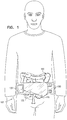
- Fig. 1 is a schematic illustration of a system 100 for estimating the position of an imaging capsule 110 inside the body of a user.
- the user swallows imaging capsule 110.
- the capsule enters the Gastro Intestinal tract and is especially useful in taking images and mapping the small intestine and colon 190.
- System 100 includes a recorder 120 to communicate 130 with imaging capsule 110 and record information provided by imaging capsule 110.
- the recorder is coupled to a strap or belt 180 to keep it fixated to the user's body in proximity to the small intestine and colon 190 as they are examined by imaging capsule 110.
- the recorder may be positioned on the front of the user, the back of the user or in any selected position.
- the position is selected empirically to provide optimal readings from transmissions provided by imaging capsule 110.
- recorder 120 analyzes transmissions from image capsule 110 to determine the spatial location of imaging capsule 110 relative to recorder 120.
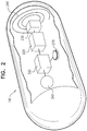
- Fig. 2 is a schematic illustration of imaging capsule 110.
- Capsule 110 includes a coil 240 for optionally transmitting a low frequency electromagnetic wave, for example at 1-50Khz.
- the transmission of electromagnetic signal may be at approximately 7 - 14 MHz and the signal can then be used for both localization and data transmission, for example using a communication system on a chip such as NxH2180 manufactured by NXP Semiconductors from Eindhoven, The Netherlands
- the communication information will be extracted from the coil with a good signal to noise ratio (SNR).
- SNR signal to noise ratio
- the transmissions are received by recorder 120 and their amplitudes are analyzed to determine the location of imaging capsule 110.
- the windings of coil 240 reside in a single plane.
- coil 240 may include windings in two or three orthogonal planes (a coil with windings in two orthogonal planes is referred to as a 2D coil and a coil with windings in three orthogonal planes is referred to as a 3D coil).
- a 3D coil transmits in three orthogonal directions and uses more energy than a coil transmitting in a single plane.
- imaging capsule 110 may be designed to use a single plane coil 240 to conserve power (e.g. provided by a battery 270), and to enable a relatively large coil that improves power efficiency.
- recorder 120 that is located outside the user's body may use a 3D coil since its power source can be larger and can easily be replaced if necessary.
- Imaging capsule 110 includes a magnetometer 230 that functions as a 3D geomagnetic sensor (e.g. MAG3110 manufactured by Freescale Semiconductors Ltd from Austin Texas). Alternatively or additionally, imaging capsule 110 includes an accelerometer 220 that functions to sense changes in the position of imaging capsule 110, for example in colon 190.
- MMA7260QT manufactured by Freescale Semiconductors LTD is an example of a small sized accelerometer that can be incorporated into imaging capsule 110.
- a combined magnetometer and accelerometer can be used, for example FXOS8700CQ manufactured by Freescale Semiconductors LTD.
- Imaging capsule 110 includes a controller 250 and a transceiver 260 to control the functionality of imaging capsule 110 and communicate with recorder 120.
- the controller 250 may include a processor and/or memory to receive and execute software instructions.
- controller 250 can receive instructions via transceiver 260, for example to start scanning and to stop scanning.
- controller 250 can transmit images recorded by imaging capsule 110 and information regarding the spatial location of the imaging capsule 110, for example the readings of the magnetometer 230 and the accelerometer 220.
- the information can notify recorder 120 regarding the orientation of imaging capsule 110 and coil 240 relative to the magnetic field and gravitational field of the earth.
- Fig. 3 is a schematic illustration of recorder 120, according to an exemplary embodiment of the disclosure.
- Recorder 120 includes a controller 350, a transceiver 360, a magnetometer 330, an accelerometer 320, a power source 370 and one or more reception coils 340.
- the one or more reception coils 340 may be single plane coils or have windings in two or three orthogonal planes (a 2D coil or a 3D coil).
- one or more reception coils 340 of recorder 120 interact with coil 240 of imaging capsule 110 by receiving the low frequency transmissions transmitted from the imaging capsule 110.
- analysis of the amplitude of the transmissions from imaging capsule 110 by a combination of reception coils 340 can be used to determine the direction and distance from recorder 120 so that the spatial location of the imaging capsule 110 can be calculated and the distance between the recorder 120 and the imaging capsule 110 can be determined.
- Readings from magnetometer 230 and accelerometer 220 are transmitted from imaging capsule 110 to recorder 120.
- Recorder 120 compares the readings with the readings of magnetometer 330 and accelerometer 320 to determine the angular direction of imaging capsule 110 and coil 240 relative to the direction of recorder 120 and the one or more reception coils 340.
- the readings of magnetometer 230 and accelerometer 220 are transmitted with a timestamp from imaging capsule 110 to synchronize comparison of the readings of magnetometer 230 and accelerometer 220 with the readings of magnetometer 330 and accelerometer 320.
- the amplitudes measured by the one or more reception coils 340 from the transmissions of coil 240 with the angular direction determined from the readings of magnetometer 230 and accelerometer 220 are used to determine the spatial location of imaging capsule 110 relative to recorder 120.
- Electromagnetic disturbances to the transmissions of coil 240 can be identified, for example by controller 350 of recorder 120 since the spatial angles of imaging capsule 110 are acquired by magnetometer 330 and accelerometer 320.
- the electromagnetic field will be disturbed differently then the constant earth magnetic field and/or the gravitational field. Therefore a sudden change in the amplitude of the transmissions from coil 240 without a matching change in the spatial orientation of the imaging capsule as recorded by the magnetometer 330 and accelerometer 320 can provide an indication regarding an electromagnetic disturbance that can be disregarded.
- the system of the invention detects these mismatching changes and disregards the reading of said measurements.
- the coil amplitude will be processes only when movement of the imaging capsule 110 is detected.
- the distance to the imaging capsule 110 is calculated using two or more reception coils 340 at recorder 120 without information from accelerometer 220 and magnetometer 230.
- the two or more reception coils may have windings in a single plane or may have windings in two or three orthogonal planes.
- at least one of the reception coils 340 is a 3D coil.
- the position is determined by testing all possible directions for the imaging capsule 110 and selecting the direction for which the two or more reception coils 340 reach agreement for the calculated position of the imaging capsule 110.
- the agreement takes into account the position difference between the two or more reception coils 340 in recorder 120.
- one of the reception coils 340 may serve as a transmitter and receiver to provide transmissions to the other reception coils 340 so that the relative distance and angles between the reception coils 340 in the recorder 120 can be measured before calculating the distance to coil 240.
- a separate transmitting reference coil is used and distance is calculated relative to that reference.
- coil 240 in imaging capsule 110 is a 3D coil that transmits simultaneously in three different frequencies, or alternatively transmits with a single frequency but the windings of each orthogonal plane transmit sequentially so that the receiver can distinguish between the three transmissions.
- a single planar reception coil 340 may be used to receive the transmissions and calculate the distance from recorder 120 and imaging capsule 110 at that moment.
- recorder 120 includes an encasement 380 ( Fig. 3 ).
- encasement 380 is coated with a high permeability material that shields the elements of recorder 120 from the influence of magnetic fields outside the body, for example such as MuMetal manufactured by The MuShield Company from Londonderry, New Hampshire, USA.
- the side facing the user's body is not coated so that it can receive transmissions from imaging capsule 110 from inside the user's body.
- the effect of the shielding if any is calibrated by recorder 120 so that it is shielded from external electromagnetic interference.
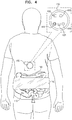
- Fig. 4 is a schematic illustration of a reference patch 410 for use with system 100 for estimating the position of imaging capsule 110.
- reference patch 410 is small like imaging capsule 110 and includes similar elements, for example an accelerometer 420, a magnetometer 430, a coil 440, a controller 450 and a transceiver 460.
- reference patch 410 is attached to the user, for example adhesively positioned on the user's back.
- the reference patch 410 serves as a stationary reference in contrast to imaging capsule 110 that dynamically moves through the user's gastro intestinal tract.
- recorder 120 communicates with reference patch 410 and with imaging capsule 110.
- recorder 120 calculates the position of the imaging capsule 110 relative to reference patch 410 to reduce recording false movements resulting from movements of recorder 120 which is optionally, larger and bulkier than reference patch 410 and more susceptible to movements since it may be attached to belt 180 and not adhesively attached to the body of the user.
- recorder 120 may be implemented in the form of reference patch 410 (e.g. in the form of a small patch attached to the user as shown in Fig. 4 ) instead of in the form of recorder 120 as shown in Fig. 1 , so that recorder 120 only needs to communicate with imaging capsule 110 and not with an additional reference patch.
- reference patch 410 may also transmit signals from coil 440 to imaging capsule 110, for example to test the communication range.
- Fig. 5 is a schematic illustration of an adaptive filter 500 for improving the accuracy in estimating the position of imaging capsule 110.
- recorder 120 uses an adaptive filter (e.g. in controller 350) to reduce noise and improve the signal to noise ratio (SNR) in the transmissions received from imaging capsule 110 (e.g. from the signals received by reception coils 340).
- SNR signal to noise ratio
- adaptive filter 500 can be set to reduce the noise (assuming that the noise while imaging capsule 110 is transmitting is similar to the noise when it is not transmitting).
- a signal received by recorder 120 from imaging capsule 110 (including noise) is fed into an input 540 of adaptive filter 500.
- the estimated noise measured while imaging capsule 110 is not transmitting is recorded and fed into a noise input 550.
- a filter 510 accepts the signal from noise input 550 and prepares it for combining with the input signal to cancel out the noise from the input signal.
- a summator 520 combines the input signal with the processed noise and provides the combined signal to an output 560 as an output signal. Additionally, the output signal is provided as feedback via a signal to noise ratio controller 530 to filter 510 to improve processing of the input signal and maximize the signal to noise ratio.
- an exemplary closed form analytic solution to calculate the distance from recorder 120 to imaging capsule 110, according to an exemplary embodiment of the disclosure.
- the spatial location of imaging capsule 110 relative to recorder 120 is known from the readings of accelerometer 220, accelerometer, 320, magnetometer 230, magnetometer 330, coil 240 with windings in one to three orthogonal planes and one reception coil 340 with windings in three orthogonal planes.
- n is the capsule coil normal vector (representing the transmission from coil 240) and r is the radius vector of the coil center.
- ⁇ ⁇ 0 I c N c ⁇ a c 2 4 ⁇
- ⁇ 0 4 ⁇ 10 -7
- Vs/(Am) is the magnetic permeability of vacuum
- I c is the electric current in the capsule coil
- N c is the number of capsule coil turns
- a c is the capsule coil effective radius
- n ( n x , n y , n z ) is the capsule coil normal vector
- r ( x - x 0 , y - y 0 , z - z 0 ) is the Cartesian distance vector between the observation point ( x 0 , y 0 , z 0 ) and the capsule coil center ( x , y
- ⁇ i 2 ⁇ N i ⁇ a i 2
- f is the field frequency
- N i is the i -th coil number of turns
- a i is the i -th coil effective radius
- n i ( n xi , n yi , n zi ) is the i -th coil normal vector
- B i is the magnetic field at the i -th coil center.
- ⁇ is the normalized vector r .
- r 0 is the radius of the circle (O) with the center in the origin and oriented orthogonally to n. Then every point in O is the solution of (1). Accordingly the solution can be found by tracking the received amplitudes.
- vector ⁇ is co-planar to the vectors n and m.
- ⁇ be the normalized vector in the plane of m and n which is orthogonal to n.
- the value of ⁇ provides us with the distance.
- previous position data are used to solve ambiguity relating to special cases, for example using historical positions near the singularity.
Landscapes
- Health & Medical Sciences (AREA)
- Life Sciences & Earth Sciences (AREA)
- Engineering & Computer Science (AREA)
- Surgery (AREA)
- Public Health (AREA)
- Molecular Biology (AREA)
- General Health & Medical Sciences (AREA)
- Physics & Mathematics (AREA)
- Animal Behavior & Ethology (AREA)
- Biophysics (AREA)
- Pathology (AREA)
- Biomedical Technology (AREA)
- Heart & Thoracic Surgery (AREA)
- Medical Informatics (AREA)
- Veterinary Medicine (AREA)
- Nuclear Medicine, Radiotherapy & Molecular Imaging (AREA)
- Optics & Photonics (AREA)
- Radiology & Medical Imaging (AREA)
- Signal Processing (AREA)
- Artificial Intelligence (AREA)
- Physiology (AREA)
- Computer Vision & Pattern Recognition (AREA)
- Psychiatry (AREA)
- Computer Networks & Wireless Communication (AREA)
- Human Computer Interaction (AREA)
- Endoscopes (AREA)
- Measurement Of The Respiration, Hearing Ability, Form, And Blood Characteristics Of Living Organisms (AREA)
Claims (12)
- System zur Positionsabschätzung (100) einer Bildgebungskapsel (110), die den Verdauungstrakt (190) eines Nutzers untersucht, umfassend:eine Bildgebungskapsel (110) zum Untersuchen des Inneren des Nutzers; einen Rekorder (120) zum Kommunizieren mit der Bildgebungskapsel (110) von außerhalb des Nutzers;und wobei die Bildgebungskapsel (110) umfasst:eine Steuerungsvorrichtung (250) zum Steuern der Funktionalität der Bildgebungskapsel (110);einen Transceiver (260) zur Kommunikation mit dem Rekorder (120);eine Spule (240) zur Übertragung elektromagnetischer Signale;ein Magnetmeter (230);einen Beschleunigungsmesser (220);wobei der Rekorder (120) umfasst:eine Steuerungsvorrichtung (350) zum Steuern der Funktionalität des Rekorders (120);einen Transceiver (360) zur Kommunikation mit der Bildgebungskapsel (110);eine Spule (340) zum Empfangen elektromagnetischer Signale von der Spule (240) der Bildgebungskapsel (110);ein Magnetometer (330);einen Beschleunigungsmesser (320);wobei die Bildgebungskapsel (110) und der Rekorder (120) derart ausgestaltet sind, dass sie den entsprechenden Transceiver (260, 360) verwenden, um ausgelesene Messwerte von dem Magnetometer (230) und dem Beschleunigungsmesser (220) von der Bildgebungskapsel (110) an den Rekorder zu übermitteln.wobei der Rekorder (120) derart ausgestaltet ist, dass er den Ort der Bildgebungskapsel (110) basierend auf Messungen der Amplitude der elektromagnetischen Signale bestimmt, die von der Spule (240) an die Bildgebungskapsel (110) übertragen werden; unddadurch gekennzeichnet ist, dassder Rekorder (120) derart ausgestaltet ist, dass er die räumliche Orientierung der Bildgebungskapsel (110) relativ zum Rekorder (120) durch Empfangen und Vergleichen von Messungen des Beschleunigungsmessers (220) und des Magnetometers (230) der Bildgebungskapsel (110) mit Messungen des Beschleunigungsmessers (320) und des Magnetometers (330) des Rekorders (120) bestimmt, und wobei er derart ausgestaltet ist, dass er den Abstand von dem Rekorder (120) zu der Bildgebungskapsel (110) unter Verwendung der bestimmten räumlichen Orientierung und der Übertragungen der Spule (240) der Bildgebungskapsel (110) und der Spule (340) des Rekorders (120) berechnet, wobei der Rekorder (120) derart ausgestaltet ist, dass er elektromagnetische Störungen der Übertragungen der Spule (240) der Bildgebungskapsel (110) durch Erfassen einer plötzlichen Änderung der Amplitude der Übertragungen der Spule (240) ohne eine entsprechende Änderung der durch das Magnetometer (330) und den Beschleunigungsmesser (320) aufgezeichneten räumlichen Orientierung der Bildgebungskapsel erkennt,wobei bei Erkennung einer elektromagnetischen Störung die Amplitude der Übertragungen aus der Spule (240) nicht beachtetet wird.
- System (100) gemäß Anspruch 1, wobei die Spule (240) in der Bildgebungskapsel (110) eine 3D-Spule mit Wicklungen in drei orthogonalen Richtungen ist, die gleichzeitig in drei verschiedenen Frequenzen senden.
- System (100) gemäß Anspruch 1, wobei die Spule (240) in der Bildgebungskapsel (110) eine 3D-Spule mit Wicklungen in drei orthogonalen Richtungen ist, die sequentiell senden.
- System (100) gemäß Anspruch 1, wobei der Rekorder (120) mindestens zwei 3D-Spulen mit Wicklungen in drei orthogonalen Richtungen umfasst und derart ausgestaltet ist, dass er den Ort der Bildgebungskapsel (110) durch Erfassen einer Richtung bestimmt, in der die Amplituden der mindestens zwei 3D-Spulen übereinstimmen.
- System (100) gemäß Anspruch 4, wobei die Übereinstimmung die Positionsdifferenz zwischen den mindestens zwei 3D-Spulen berücksichtigt.
- System (100) gemäß Anspruch 1, wobei die Messwerte mit einem Zeitstempel übermittelt werden.
- System (100) gemäß Anspruch 1, wobei der Rekorder (120) derart ausgestaltet ist, dass er einen adaptiven Filter (500) verwendet, um das Signal-Rausch-Verhältnis der von der Spule (240) der Bildgebungskapsel (110) empfangenen Übertragungen zu verbessern.
- System (100) gemäß Anspruch 1, wobei die Spule (240) in der Bildgebungskapsel (110) Wicklungen in einer einzigen Ebene umfasst.
- System (100) gemäß Anspruch 1, ferner umfassend:ein Referenzpflaster (410);wobei das Referenzpflaster (410) umfasst:eine Steuerungsvorrichtung (450) zum Steuern der Funktionalität des Referenzpflasters (410);einen Transceiver (460) zur Kommunikation mit dem Rekorder (120);eine Spule (440) zur Übertragung elektromagnetischer Signale;wobei das Referenzpflaster (410) derart ausgestaltet ist, dass es an den Körper des Nutzers an einer unterschiedlichen Position als der Rekorder (120) angebracht ist und relativ zum Nutzer ortsfest ist, wobei es anders als die sich dynamisch bewegende Bildgebungskapsel als ein ortsfester Referenzpunkt dient, und wobei der Rekorder (120) Messungen der Amplitude der elektromagnetischen Signale von der Bildgebungskapsel (110) mit Messungen der Amplitude der elektromagnetischen Signale von dem Referenzpflaster (410) vergleicht, um aus Bewegungen des Rekorders (120) sich ergebende Fehler zu eliminieren.
- System (100) gemäß Anspruch 9, wobei das Referenzpflaster (410) ein Magnetometer (430) oder einen Beschleunigungsmesser (420) oder beides umfasst.
- System (100) gemäß Anspruch 10, wobei das Referenzpflaster (410) derart ausgestaltet ist, um den Transceiver (460) zum Übermitteln von Messungen aus dem Magnetometer (430), der Spule (440) und dem Beschleunigungsmesser (420) an dem Rekorder (120) zu verwenden.
- System (100) gemäß Anspruch 1, wobei der Rekorder (120) ein Gehäuse (380) umfasst; wobei das Gehäuse (380) mit einem hochpermeablen Material beschichtet ist, das Elemente des Rekorders (120) von dem Einfluss des magnetischen Feldes abschirmt; und wobei eine zum Nutzer schauende Seite des Gehäuses (380) nicht beschichtet ist.
Applications Claiming Priority (4)
| Application Number | Priority Date | Filing Date | Title |
|---|---|---|---|
| US201361831163P | 2013-06-05 | 2013-06-05 | |
| US201361903998P | 2013-11-14 | 2013-11-14 | |
| US201461931742P | 2014-01-27 | 2014-01-27 | |
| PCT/IL2014/050404 WO2014195934A1 (en) | 2013-06-05 | 2014-05-05 | Position estimation of imaging capsule in gastrointestinal tract |
Publications (3)
| Publication Number | Publication Date |
|---|---|
| EP3003118A1 EP3003118A1 (de) | 2016-04-13 |
| EP3003118A4 EP3003118A4 (de) | 2017-01-25 |
| EP3003118B1 true EP3003118B1 (de) | 2021-11-10 |
Family
ID=52007647
Family Applications (1)
| Application Number | Title | Priority Date | Filing Date |
|---|---|---|---|
| EP14807239.0A Active EP3003118B1 (de) | 2013-06-05 | 2014-05-05 | Positionsschätzung einer bildgebungskapsel im verdauungstrakt |
Country Status (6)
| Country | Link |
|---|---|
| US (1) | US11147468B2 (de) |
| EP (1) | EP3003118B1 (de) |
| JP (1) | JP6475699B2 (de) |
| CN (1) | CN105208911B (de) |
| IL (1) | IL242120B (de) |
| WO (1) | WO2014195934A1 (de) |
Families Citing this family (3)
| Publication number | Priority date | Publication date | Assignee | Title |
|---|---|---|---|---|
| EP3457936B1 (de) * | 2016-08-01 | 2020-09-02 | Check-Cap Ltd. | Bildwiederherstellung mit radioaktiver bildgebungskapsel |
| EP3826527B1 (de) * | 2018-07-25 | 2023-12-13 | Check-Cap Ltd. | System und verfahren zur polypendetektion durch kapseldynamik |
| US20230410336A1 (en) * | 2022-06-15 | 2023-12-21 | CapsoVision, Inc. | Method and Apparatus for Identifying Capsule Camera Location inside Gastrointestinal Tract |
Family Cites Families (34)
| Publication number | Priority date | Publication date | Assignee | Title |
|---|---|---|---|---|
| IL108352A (en) | 1994-01-17 | 2000-02-29 | Given Imaging Ltd | In vivo video camera system |
| ATE252349T1 (de) * | 1994-09-15 | 2003-11-15 | Visualization Technology Inc | System zur positionserfassung mittels einer an einem patientenkopf angebrachten referenzeinheit zur anwendung im medizinischen gebiet |
| AU3197699A (en) * | 1998-03-30 | 1999-10-18 | Biosense, Inc. | Three-axis coil sensor |
| US6368285B1 (en) * | 1999-09-21 | 2002-04-09 | Biosense, Inc. | Method and apparatus for mapping a chamber of a heart |
| US7039453B2 (en) | 2000-02-08 | 2006-05-02 | Tarun Mullick | Miniature ingestible capsule |
| US6716166B2 (en) * | 2000-08-18 | 2004-04-06 | Biosense, Inc. | Three-dimensional reconstruction using ultrasound |
| US20020099310A1 (en) | 2001-01-22 | 2002-07-25 | V-Target Ltd. | Gastrointestinal-tract sensor |
| US6725085B2 (en) * | 2000-09-22 | 2004-04-20 | Armin Schwartzman | Method and apparatus for characterizing cardiac tissue from local electrograms |
| AU2002307762A1 (en) * | 2001-04-18 | 2002-10-28 | Bbms Ltd. | Navigating and maneuvering of an in vivo vechicle by extracorporeal devices |
| IL143260A (en) * | 2001-05-20 | 2006-09-05 | Given Imaging Ltd | Array and method for locating an intra-body signal source |
| WO2003028224A2 (en) * | 2001-09-24 | 2003-04-03 | Given Imaging Ltd. | System and method for controlling a device in vivo |
| US7697972B2 (en) * | 2002-11-19 | 2010-04-13 | Medtronic Navigation, Inc. | Navigation system for cardiac therapies |
| CN1747679B (zh) * | 2003-02-04 | 2012-10-03 | 奥林巴斯株式会社 | 医疗装置引导系统及其控制方法 |
| US20040243148A1 (en) * | 2003-04-08 | 2004-12-02 | Wasielewski Ray C. | Use of micro- and miniature position sensing devices for use in TKA and THA |
| ATE517576T1 (de) | 2003-12-17 | 2011-08-15 | Check Cap Ltd | Intralumen-polyp-nachweis |
| JP4455067B2 (ja) * | 2004-01-14 | 2010-04-21 | オリンパス株式会社 | カプセル型内視鏡装置 |
| EP1718203B1 (de) * | 2004-02-18 | 2012-08-15 | Philips Intellectual Property & Standards GmbH | Korrektur von messwerten für eine magnetische lokalisierungsvorrichtung |
| EP1731093B1 (de) * | 2004-03-29 | 2013-01-09 | Olympus Corporation | System zum nachweis der position in einem untersuchten |
| US20080039687A1 (en) * | 2004-10-15 | 2008-02-14 | Hatsuo Shimizu | Radio Intra-Subject Information Acquiring System |
| DE602005007847D1 (de) | 2004-12-30 | 2008-08-14 | Given Imaging Ltd | System zur Lokalisation einer in-Vivo Signalquelle |
| JP4813190B2 (ja) * | 2005-05-26 | 2011-11-09 | オリンパスメディカルシステムズ株式会社 | カプセル型医療装置 |
| DE102005045362B4 (de) * | 2005-09-22 | 2012-03-22 | Siemens Ag | Vorrichtung zur Positionsbestimmung eines medizinischen Instruments, dazugehörige bildgebende Untersuchungseinrichtung nebst dazugehörigem Verfahren |
| KR100990287B1 (ko) * | 2005-10-06 | 2010-10-26 | 올림푸스 가부시키가이샤 | 위치 검출 시스템 |
| DE602006021611D1 (de) * | 2005-12-02 | 2011-06-09 | Olympus Corp | System zum nachweis der position eines medizinprodukts, führungssystem für ein medizinprodukt und verfahren zum nachweis der position eines medizinprodukts |
| WO2007074445A2 (en) * | 2005-12-29 | 2007-07-05 | Given Imaging Ltd. | System and method of in-vivo magnetic position determination |
| US9844354B2 (en) * | 2007-02-06 | 2017-12-19 | Check-Cap Ltd. | Intra-lumen polyp detection |
| JP2008220522A (ja) * | 2007-03-09 | 2008-09-25 | Hoya Corp | 姿勢検出ユニット、記憶ユニット、相対姿勢算出ユニット、相対姿勢検出システム、およびカプセル内視鏡姿勢検出システム |
| JP5019589B2 (ja) * | 2007-03-28 | 2012-09-05 | 富士フイルム株式会社 | カプセル内視鏡、およびカプセル内視鏡システム、並びにカプセル内視鏡の作動方法 |
| US7826999B1 (en) * | 2007-08-20 | 2010-11-02 | Pni Corporation | Magnetic tilt compensated heading compass with adaptive zoffset |
| WO2009044384A2 (fr) * | 2007-10-04 | 2009-04-09 | MOTILIS Sàrl | Dispositif de mesure et méthode d'analyse de la motilité gastro-intestinale |
| US8494608B2 (en) * | 2008-04-18 | 2013-07-23 | Medtronic, Inc. | Method and apparatus for mapping a structure |
| WO2012056323A2 (en) * | 2010-10-29 | 2012-05-03 | Check-Cap Ltd. | Intra body capsule motion sensing and position determination systems and methods |
| WO2014113697A1 (en) * | 2013-01-17 | 2014-07-24 | Vanderbilt University | Real-time pose and magnetic force detection for wireless magnetic capsule |
| US20150238118A1 (en) * | 2014-02-27 | 2015-08-27 | Biorasis, Inc. | Detection of the spatial location of an implantable biosensing platform and method thereof |
-
2014
- 2014-05-05 EP EP14807239.0A patent/EP3003118B1/de active Active
- 2014-05-05 US US14/785,860 patent/US11147468B2/en not_active Expired - Fee Related
- 2014-05-05 CN CN201480028004.9A patent/CN105208911B/zh not_active Expired - Fee Related
- 2014-05-05 JP JP2016517739A patent/JP6475699B2/ja not_active Expired - Fee Related
- 2014-05-05 WO PCT/IL2014/050404 patent/WO2014195934A1/en not_active Ceased
-
2015
- 2015-10-15 IL IL242120A patent/IL242120B/en unknown
Non-Patent Citations (1)
| Title |
|---|
| None * |
Also Published As
| Publication number | Publication date |
|---|---|
| US11147468B2 (en) | 2021-10-19 |
| JP2016523131A (ja) | 2016-08-08 |
| EP3003118A1 (de) | 2016-04-13 |
| EP3003118A4 (de) | 2017-01-25 |
| CN105208911A (zh) | 2015-12-30 |
| JP6475699B2 (ja) | 2019-02-27 |
| CN105208911B (zh) | 2017-08-18 |
| US20160066813A1 (en) | 2016-03-10 |
| WO2014195934A1 (en) | 2014-12-11 |
| IL242120B (en) | 2021-10-31 |
Similar Documents
| Publication | Publication Date | Title |
|---|---|---|
| Than et al. | A review of localization systems for robotic endoscopic capsules | |
| CN100594840C (zh) | 一种跟踪体内微型装置的方法 | |
| US9562986B2 (en) | Walk through metal detection system | |
| US8571636B2 (en) | Shielded surgical navigation system that determines the position and orientation of the tracked object with real and virtual dipoles | |
| US20070002038A1 (en) | Intra-subject position display system | |
| US20140031642A1 (en) | Intra body capsule motion sensing and position determination systems and methods | |
| Ye et al. | Accuracy of RSS-based RF localization in multi-capsule endoscopy | |
| US8740772B2 (en) | Position information estimation system | |
| JP2006271987A (ja) | 生体内信号源の位置を探知するアレーシステム及び方法 | |
| US20130182829A1 (en) | Alignment systems | |
| US12313730B2 (en) | Systems and methods for imaging concealed surfaces | |
| EP3003118B1 (de) | Positionsschätzung einer bildgebungskapsel im verdauungstrakt | |
| KR20160111771A (ko) | 초광대역 임펄스 레이다 신호를 이용한 마이크로 로봇 위치 인식 방법 및 그에 따른 인식 장치 | |
| Zeising et al. | Localization of passively guided capsule endoscopes—A review | |
| EP2842476B1 (de) | Positionsbestimmungsvorrichtung, kapselendoskopsystem und positionsbestimmungsprogramm | |
| Ali et al. | Recent Advancements in Localization Technologies for Wireless Capsule Endoscopy: A Technical Review | |
| Gu et al. | A multi-radar wireless system for respiratory gating and accurate tumor tracking in lung cancer radiotherapy | |
| CN1937953A (zh) | 被检体内位置检测系统 | |
| EP3826527B1 (de) | System und verfahren zur polypendetektion durch kapseldynamik | |
| Ara et al. | Investigation of in-body path loss in different human subjects for localization of capsule endoscope | |
| Chi et al. | Research on localization control of magneto-controlled capsule endoscopy based on sensor array | |
| Skos et al. | Magnetic Localization for In-Body Nano-Communication Medical Systems | |
| CN219594565U (zh) | 全身扫描仪 |
Legal Events
| Date | Code | Title | Description |
|---|---|---|---|
| PUAI | Public reference made under article 153(3) epc to a published international application that has entered the european phase |
Free format text: ORIGINAL CODE: 0009012 |
|
| 17P | Request for examination filed |
Effective date: 20151021 |
|
| AK | Designated contracting states |
Kind code of ref document: A1 Designated state(s): AL AT BE BG CH CY CZ DE DK EE ES FI FR GB GR HR HU IE IS IT LI LT LU LV MC MK MT NL NO PL PT RO RS SE SI SK SM TR |
|
| AX | Request for extension of the european patent |
Extension state: BA ME |
|
| DAX | Request for extension of the european patent (deleted) | ||
| A4 | Supplementary search report drawn up and despatched |
Effective date: 20161223 |
|
| RIC1 | Information provided on ipc code assigned before grant |
Ipc: A61B 1/00 20060101AFI20161219BHEP |
|
| STAA | Information on the status of an ep patent application or granted ep patent |
Free format text: STATUS: EXAMINATION IS IN PROGRESS |
|
| 17Q | First examination report despatched |
Effective date: 20180116 |
|
| REG | Reference to a national code |
Ref country code: DE Ref legal event code: R079 Ref document number: 602014081200 Country of ref document: DE Free format text: PREVIOUS MAIN CLASS: A61B0001000000 Ipc: A61B0001040000 |
|
| GRAP | Despatch of communication of intention to grant a patent |
Free format text: ORIGINAL CODE: EPIDOSNIGR1 |
|
| STAA | Information on the status of an ep patent application or granted ep patent |
Free format text: STATUS: GRANT OF PATENT IS INTENDED |
|
| RIC1 | Information provided on ipc code assigned before grant |
Ipc: A61B 1/04 20060101AFI20210709BHEP Ipc: A61B 5/06 20060101ALI20210709BHEP |
|
| INTG | Intention to grant announced |
Effective date: 20210809 |
|
| GRAS | Grant fee paid |
Free format text: ORIGINAL CODE: EPIDOSNIGR3 |
|
| GRAA | (expected) grant |
Free format text: ORIGINAL CODE: 0009210 |
|
| STAA | Information on the status of an ep patent application or granted ep patent |
Free format text: STATUS: THE PATENT HAS BEEN GRANTED |
|
| AK | Designated contracting states |
Kind code of ref document: B1 Designated state(s): AL AT BE BG CH CY CZ DE DK EE ES FI FR GB GR HR HU IE IS IT LI LT LU LV MC MK MT NL NO PL PT RO RS SE SI SK SM TR |
|
| REG | Reference to a national code |
Ref country code: GB Ref legal event code: FG4D |
|
| REG | Reference to a national code |
Ref country code: AT Ref legal event code: REF Ref document number: 1445305 Country of ref document: AT Kind code of ref document: T Effective date: 20211115 Ref country code: CH Ref legal event code: EP |
|
| REG | Reference to a national code |
Ref country code: DE Ref legal event code: R096 Ref document number: 602014081200 Country of ref document: DE |
|
| REG | Reference to a national code |
Ref country code: IE Ref legal event code: FG4D |
|
| REG | Reference to a national code |
Ref country code: LT Ref legal event code: MG9D |
|
| REG | Reference to a national code |
Ref country code: NL Ref legal event code: MP Effective date: 20211110 |
|
| REG | Reference to a national code |
Ref country code: AT Ref legal event code: MK05 Ref document number: 1445305 Country of ref document: AT Kind code of ref document: T Effective date: 20211110 |
|
| PG25 | Lapsed in a contracting state [announced via postgrant information from national office to epo] |
Ref country code: RS Free format text: LAPSE BECAUSE OF FAILURE TO SUBMIT A TRANSLATION OF THE DESCRIPTION OR TO PAY THE FEE WITHIN THE PRESCRIBED TIME-LIMIT Effective date: 20211110 Ref country code: LT Free format text: LAPSE BECAUSE OF FAILURE TO SUBMIT A TRANSLATION OF THE DESCRIPTION OR TO PAY THE FEE WITHIN THE PRESCRIBED TIME-LIMIT Effective date: 20211110 Ref country code: FI Free format text: LAPSE BECAUSE OF FAILURE TO SUBMIT A TRANSLATION OF THE DESCRIPTION OR TO PAY THE FEE WITHIN THE PRESCRIBED TIME-LIMIT Effective date: 20211110 Ref country code: BG Free format text: LAPSE BECAUSE OF FAILURE TO SUBMIT A TRANSLATION OF THE DESCRIPTION OR TO PAY THE FEE WITHIN THE PRESCRIBED TIME-LIMIT Effective date: 20220210 Ref country code: AT Free format text: LAPSE BECAUSE OF FAILURE TO SUBMIT A TRANSLATION OF THE DESCRIPTION OR TO PAY THE FEE WITHIN THE PRESCRIBED TIME-LIMIT Effective date: 20211110 |
|
| PG25 | Lapsed in a contracting state [announced via postgrant information from national office to epo] |
Ref country code: IS Free format text: LAPSE BECAUSE OF FAILURE TO SUBMIT A TRANSLATION OF THE DESCRIPTION OR TO PAY THE FEE WITHIN THE PRESCRIBED TIME-LIMIT Effective date: 20220310 Ref country code: SE Free format text: LAPSE BECAUSE OF FAILURE TO SUBMIT A TRANSLATION OF THE DESCRIPTION OR TO PAY THE FEE WITHIN THE PRESCRIBED TIME-LIMIT Effective date: 20211110 Ref country code: PT Free format text: LAPSE BECAUSE OF FAILURE TO SUBMIT A TRANSLATION OF THE DESCRIPTION OR TO PAY THE FEE WITHIN THE PRESCRIBED TIME-LIMIT Effective date: 20220310 Ref country code: PL Free format text: LAPSE BECAUSE OF FAILURE TO SUBMIT A TRANSLATION OF THE DESCRIPTION OR TO PAY THE FEE WITHIN THE PRESCRIBED TIME-LIMIT Effective date: 20211110 Ref country code: NO Free format text: LAPSE BECAUSE OF FAILURE TO SUBMIT A TRANSLATION OF THE DESCRIPTION OR TO PAY THE FEE WITHIN THE PRESCRIBED TIME-LIMIT Effective date: 20220210 Ref country code: NL Free format text: LAPSE BECAUSE OF FAILURE TO SUBMIT A TRANSLATION OF THE DESCRIPTION OR TO PAY THE FEE WITHIN THE PRESCRIBED TIME-LIMIT Effective date: 20211110 Ref country code: LV Free format text: LAPSE BECAUSE OF FAILURE TO SUBMIT A TRANSLATION OF THE DESCRIPTION OR TO PAY THE FEE WITHIN THE PRESCRIBED TIME-LIMIT Effective date: 20211110 Ref country code: HR Free format text: LAPSE BECAUSE OF FAILURE TO SUBMIT A TRANSLATION OF THE DESCRIPTION OR TO PAY THE FEE WITHIN THE PRESCRIBED TIME-LIMIT Effective date: 20211110 Ref country code: GR Free format text: LAPSE BECAUSE OF FAILURE TO SUBMIT A TRANSLATION OF THE DESCRIPTION OR TO PAY THE FEE WITHIN THE PRESCRIBED TIME-LIMIT Effective date: 20220211 Ref country code: ES Free format text: LAPSE BECAUSE OF FAILURE TO SUBMIT A TRANSLATION OF THE DESCRIPTION OR TO PAY THE FEE WITHIN THE PRESCRIBED TIME-LIMIT Effective date: 20211110 |
|
| PG25 | Lapsed in a contracting state [announced via postgrant information from national office to epo] |
Ref country code: SM Free format text: LAPSE BECAUSE OF FAILURE TO SUBMIT A TRANSLATION OF THE DESCRIPTION OR TO PAY THE FEE WITHIN THE PRESCRIBED TIME-LIMIT Effective date: 20211110 Ref country code: SK Free format text: LAPSE BECAUSE OF FAILURE TO SUBMIT A TRANSLATION OF THE DESCRIPTION OR TO PAY THE FEE WITHIN THE PRESCRIBED TIME-LIMIT Effective date: 20211110 Ref country code: RO Free format text: LAPSE BECAUSE OF FAILURE TO SUBMIT A TRANSLATION OF THE DESCRIPTION OR TO PAY THE FEE WITHIN THE PRESCRIBED TIME-LIMIT Effective date: 20211110 Ref country code: EE Free format text: LAPSE BECAUSE OF FAILURE TO SUBMIT A TRANSLATION OF THE DESCRIPTION OR TO PAY THE FEE WITHIN THE PRESCRIBED TIME-LIMIT Effective date: 20211110 Ref country code: DK Free format text: LAPSE BECAUSE OF FAILURE TO SUBMIT A TRANSLATION OF THE DESCRIPTION OR TO PAY THE FEE WITHIN THE PRESCRIBED TIME-LIMIT Effective date: 20211110 Ref country code: CZ Free format text: LAPSE BECAUSE OF FAILURE TO SUBMIT A TRANSLATION OF THE DESCRIPTION OR TO PAY THE FEE WITHIN THE PRESCRIBED TIME-LIMIT Effective date: 20211110 |
|
| REG | Reference to a national code |
Ref country code: DE Ref legal event code: R097 Ref document number: 602014081200 Country of ref document: DE |
|
| PLBE | No opposition filed within time limit |
Free format text: ORIGINAL CODE: 0009261 |
|
| STAA | Information on the status of an ep patent application or granted ep patent |
Free format text: STATUS: NO OPPOSITION FILED WITHIN TIME LIMIT |
|
| 26N | No opposition filed |
Effective date: 20220811 |
|
| PG25 | Lapsed in a contracting state [announced via postgrant information from national office to epo] |
Ref country code: AL Free format text: LAPSE BECAUSE OF FAILURE TO SUBMIT A TRANSLATION OF THE DESCRIPTION OR TO PAY THE FEE WITHIN THE PRESCRIBED TIME-LIMIT Effective date: 20211110 |
|
| PG25 | Lapsed in a contracting state [announced via postgrant information from national office to epo] |
Ref country code: SI Free format text: LAPSE BECAUSE OF FAILURE TO SUBMIT A TRANSLATION OF THE DESCRIPTION OR TO PAY THE FEE WITHIN THE PRESCRIBED TIME-LIMIT Effective date: 20211110 |
|
| REG | Reference to a national code |
Ref country code: BE Ref legal event code: MM Effective date: 20220531 |
|
| PG25 | Lapsed in a contracting state [announced via postgrant information from national office to epo] |
Ref country code: MC Free format text: LAPSE BECAUSE OF FAILURE TO SUBMIT A TRANSLATION OF THE DESCRIPTION OR TO PAY THE FEE WITHIN THE PRESCRIBED TIME-LIMIT Effective date: 20211110 Ref country code: LU Free format text: LAPSE BECAUSE OF NON-PAYMENT OF DUE FEES Effective date: 20220505 |
|
| PG25 | Lapsed in a contracting state [announced via postgrant information from national office to epo] |
Ref country code: IE Free format text: LAPSE BECAUSE OF NON-PAYMENT OF DUE FEES Effective date: 20220505 |
|
| PG25 | Lapsed in a contracting state [announced via postgrant information from national office to epo] |
Ref country code: BE Free format text: LAPSE BECAUSE OF NON-PAYMENT OF DUE FEES Effective date: 20220531 |
|
| PGFP | Annual fee paid to national office [announced via postgrant information from national office to epo] |
Ref country code: IT Payment date: 20230526 Year of fee payment: 10 Ref country code: FR Payment date: 20230526 Year of fee payment: 10 Ref country code: DE Payment date: 20230519 Year of fee payment: 10 Ref country code: CH Payment date: 20230602 Year of fee payment: 10 |
|
| PGFP | Annual fee paid to national office [announced via postgrant information from national office to epo] |
Ref country code: GB Payment date: 20230524 Year of fee payment: 10 |
|
| PG25 | Lapsed in a contracting state [announced via postgrant information from national office to epo] |
Ref country code: HU Free format text: LAPSE BECAUSE OF FAILURE TO SUBMIT A TRANSLATION OF THE DESCRIPTION OR TO PAY THE FEE WITHIN THE PRESCRIBED TIME-LIMIT; INVALID AB INITIO Effective date: 20140505 |
|
| PG25 | Lapsed in a contracting state [announced via postgrant information from national office to epo] |
Ref country code: MK Free format text: LAPSE BECAUSE OF FAILURE TO SUBMIT A TRANSLATION OF THE DESCRIPTION OR TO PAY THE FEE WITHIN THE PRESCRIBED TIME-LIMIT Effective date: 20211110 Ref country code: CY Free format text: LAPSE BECAUSE OF FAILURE TO SUBMIT A TRANSLATION OF THE DESCRIPTION OR TO PAY THE FEE WITHIN THE PRESCRIBED TIME-LIMIT Effective date: 20211110 |
|
| PG25 | Lapsed in a contracting state [announced via postgrant information from national office to epo] |
Ref country code: MT Free format text: LAPSE BECAUSE OF FAILURE TO SUBMIT A TRANSLATION OF THE DESCRIPTION OR TO PAY THE FEE WITHIN THE PRESCRIBED TIME-LIMIT Effective date: 20211110 |
|
| REG | Reference to a national code |
Ref country code: DE Ref legal event code: R119 Ref document number: 602014081200 Country of ref document: DE |
|
| REG | Reference to a national code |
Ref country code: CH Ref legal event code: PL |
|
| GBPC | Gb: european patent ceased through non-payment of renewal fee |
Effective date: 20240505 |
|
| PG25 | Lapsed in a contracting state [announced via postgrant information from national office to epo] |
Ref country code: CH Free format text: LAPSE BECAUSE OF NON-PAYMENT OF DUE FEES Effective date: 20240531 |
|
| PG25 | Lapsed in a contracting state [announced via postgrant information from national office to epo] |
Ref country code: DE Free format text: LAPSE BECAUSE OF NON-PAYMENT OF DUE FEES Effective date: 20241203 |
|
| PG25 | Lapsed in a contracting state [announced via postgrant information from national office to epo] |
Ref country code: FR Free format text: LAPSE BECAUSE OF NON-PAYMENT OF DUE FEES Effective date: 20240531 |
|
| PG25 | Lapsed in a contracting state [announced via postgrant information from national office to epo] |
Ref country code: IT Free format text: LAPSE BECAUSE OF NON-PAYMENT OF DUE FEES Effective date: 20240505 Ref country code: GB Free format text: LAPSE BECAUSE OF NON-PAYMENT OF DUE FEES Effective date: 20240505 |
|
| PG25 | Lapsed in a contracting state [announced via postgrant information from national office to epo] |
Ref country code: TR Free format text: LAPSE BECAUSE OF FAILURE TO SUBMIT A TRANSLATION OF THE DESCRIPTION OR TO PAY THE FEE WITHIN THE PRESCRIBED TIME-LIMIT Effective date: 20211110 |