EP3002881B2 - Système et procédé de synchronisation temporelle de liaison montante en conjonction avec une réception discontinue - Google Patents
Système et procédé de synchronisation temporelle de liaison montante en conjonction avec une réception discontinue Download PDFInfo
- Publication number
- EP3002881B2 EP3002881B2 EP15194137.4A EP15194137A EP3002881B2 EP 3002881 B2 EP3002881 B2 EP 3002881B2 EP 15194137 A EP15194137 A EP 15194137A EP 3002881 B2 EP3002881 B2 EP 3002881B2
- Authority
- EP
- European Patent Office
- Prior art keywords
- srs
- network
- drx
- uplink
- network access
- Prior art date
- Legal status (The legal status is an assumption and is not a legal conclusion. Google has not performed a legal analysis and makes no representation as to the accuracy of the status listed.)
- Active
Links
- 238000000034 method Methods 0.000 title claims description 22
- 230000007774 longterm Effects 0.000 claims description 3
- 230000005540 biological transmission Effects 0.000 description 49
- 238000012545 processing Methods 0.000 description 25
- 238000004891 communication Methods 0.000 description 24
- 230000006870 function Effects 0.000 description 18
- 230000001413 cellular effect Effects 0.000 description 14
- 238000010586 diagram Methods 0.000 description 14
- 230000015654 memory Effects 0.000 description 13
- 230000008054 signal transmission Effects 0.000 description 8
- 230000000694 effects Effects 0.000 description 6
- 230000001131 transforming effect Effects 0.000 description 6
- 238000005516 engineering process Methods 0.000 description 5
- 230000011664 signaling Effects 0.000 description 5
- 125000004122 cyclic group Chemical group 0.000 description 4
- 101150014328 RAN2 gene Proteins 0.000 description 3
- 230000006399 behavior Effects 0.000 description 3
- 230000008859 change Effects 0.000 description 3
- 238000011156 evaluation Methods 0.000 description 3
- 238000007726 management method Methods 0.000 description 3
- 230000007246 mechanism Effects 0.000 description 3
- 230000004044 response Effects 0.000 description 3
- 230000007480 spreading Effects 0.000 description 3
- 101150069124 RAN1 gene Proteins 0.000 description 2
- 101100355633 Salmo salar ran gene Proteins 0.000 description 2
- 238000006243 chemical reaction Methods 0.000 description 2
- 238000013500 data storage Methods 0.000 description 2
- 230000000994 depressogenic effect Effects 0.000 description 2
- 238000012905 input function Methods 0.000 description 2
- 239000004973 liquid crystal related substance Substances 0.000 description 2
- 230000003287 optical effect Effects 0.000 description 2
- 230000002093 peripheral effect Effects 0.000 description 2
- 230000008569 process Effects 0.000 description 2
- 241000699670 Mus sp. Species 0.000 description 1
- 239000000969 carrier Substances 0.000 description 1
- 238000004590 computer program Methods 0.000 description 1
- 239000004020 conductor Substances 0.000 description 1
- 238000013479 data entry Methods 0.000 description 1
- 230000003247 decreasing effect Effects 0.000 description 1
- 239000000835 fiber Substances 0.000 description 1
- 230000003993 interaction Effects 0.000 description 1
- 238000012423 maintenance Methods 0.000 description 1
- 238000010295 mobile communication Methods 0.000 description 1
- 239000013307 optical fiber Substances 0.000 description 1
- 238000013515 script Methods 0.000 description 1
- 238000001774 stimulated Raman spectroscopy Methods 0.000 description 1
- 238000012546 transfer Methods 0.000 description 1
- 230000001960 triggered effect Effects 0.000 description 1
Images


Classifications
-
- H—ELECTRICITY
- H04—ELECTRIC COMMUNICATION TECHNIQUE
- H04W—WIRELESS COMMUNICATION NETWORKS
- H04W56/00—Synchronisation arrangements
-
- H—ELECTRICITY
- H04—ELECTRIC COMMUNICATION TECHNIQUE
- H04W—WIRELESS COMMUNICATION NETWORKS
- H04W52/00—Power management, e.g. TPC [Transmission Power Control], power saving or power classes
- H04W52/02—Power saving arrangements
- H04W52/0209—Power saving arrangements in terminal devices
- H04W52/0212—Power saving arrangements in terminal devices managed by the network, e.g. network or access point is master and terminal is slave
- H04W52/0216—Power saving arrangements in terminal devices managed by the network, e.g. network or access point is master and terminal is slave using a pre-established activity schedule, e.g. traffic indication frame
-
- H—ELECTRICITY
- H04—ELECTRIC COMMUNICATION TECHNIQUE
- H04L—TRANSMISSION OF DIGITAL INFORMATION, e.g. TELEGRAPHIC COMMUNICATION
- H04L25/00—Baseband systems
- H04L25/02—Details ; arrangements for supplying electrical power along data transmission lines
- H04L25/0202—Channel estimation
- H04L25/0224—Channel estimation using sounding signals
-
- H—ELECTRICITY
- H04—ELECTRIC COMMUNICATION TECHNIQUE
- H04L—TRANSMISSION OF DIGITAL INFORMATION, e.g. TELEGRAPHIC COMMUNICATION
- H04L5/00—Arrangements affording multiple use of the transmission path
- H04L5/003—Arrangements for allocating sub-channels of the transmission path
- H04L5/0048—Allocation of pilot signals, i.e. of signals known to the receiver
-
- H—ELECTRICITY
- H04—ELECTRIC COMMUNICATION TECHNIQUE
- H04W—WIRELESS COMMUNICATION NETWORKS
- H04W52/00—Power management, e.g. TPC [Transmission Power Control], power saving or power classes
- H04W52/02—Power saving arrangements
-
- H—ELECTRICITY
- H04—ELECTRIC COMMUNICATION TECHNIQUE
- H04W—WIRELESS COMMUNICATION NETWORKS
- H04W52/00—Power management, e.g. TPC [Transmission Power Control], power saving or power classes
- H04W52/02—Power saving arrangements
- H04W52/0209—Power saving arrangements in terminal devices
-
- H—ELECTRICITY
- H04—ELECTRIC COMMUNICATION TECHNIQUE
- H04W—WIRELESS COMMUNICATION NETWORKS
- H04W56/00—Synchronisation arrangements
- H04W56/0005—Synchronisation arrangements synchronizing of arrival of multiple uplinks
-
- H—ELECTRICITY
- H04—ELECTRIC COMMUNICATION TECHNIQUE
- H04W—WIRELESS COMMUNICATION NETWORKS
- H04W56/00—Synchronisation arrangements
- H04W56/001—Synchronization between nodes
- H04W56/0015—Synchronization between nodes one node acting as a reference for the others
-
- H—ELECTRICITY
- H04—ELECTRIC COMMUNICATION TECHNIQUE
- H04W—WIRELESS COMMUNICATION NETWORKS
- H04W72/00—Local resource management
- H04W72/20—Control channels or signalling for resource management
- H04W72/21—Control channels or signalling for resource management in the uplink direction of a wireless link, i.e. towards the network
-
- H—ELECTRICITY
- H04—ELECTRIC COMMUNICATION TECHNIQUE
- H04W—WIRELESS COMMUNICATION NETWORKS
- H04W76/00—Connection management
- H04W76/20—Manipulation of established connections
- H04W76/28—Discontinuous transmission [DTX]; Discontinuous reception [DRX]
-
- H—ELECTRICITY
- H04—ELECTRIC COMMUNICATION TECHNIQUE
- H04W—WIRELESS COMMUNICATION NETWORKS
- H04W88/00—Devices specially adapted for wireless communication networks, e.g. terminals, base stations or access point devices
- H04W88/02—Terminal devices
-
- H—ELECTRICITY
- H04—ELECTRIC COMMUNICATION TECHNIQUE
- H04W—WIRELESS COMMUNICATION NETWORKS
- H04W88/00—Devices specially adapted for wireless communication networks, e.g. terminals, base stations or access point devices
- H04W88/08—Access point devices
-
- Y—GENERAL TAGGING OF NEW TECHNOLOGICAL DEVELOPMENTS; GENERAL TAGGING OF CROSS-SECTIONAL TECHNOLOGIES SPANNING OVER SEVERAL SECTIONS OF THE IPC; TECHNICAL SUBJECTS COVERED BY FORMER USPC CROSS-REFERENCE ART COLLECTIONS [XRACs] AND DIGESTS
- Y02—TECHNOLOGIES OR APPLICATIONS FOR MITIGATION OR ADAPTATION AGAINST CLIMATE CHANGE
- Y02D—CLIMATE CHANGE MITIGATION TECHNOLOGIES IN INFORMATION AND COMMUNICATION TECHNOLOGIES [ICT], I.E. INFORMATION AND COMMUNICATION TECHNOLOGIES AIMING AT THE REDUCTION OF THEIR OWN ENERGY USE
- Y02D30/00—Reducing energy consumption in communication networks
- Y02D30/70—Reducing energy consumption in communication networks in wireless communication networks
Definitions
- the application relates to uplink timing synchronization in a wireless communication system.
- LTE long-term evolution
- LTE long-term evolution
- the region in which a wireless device can gain access to a telecommunications network might be referred to by a name other than "cell", such as "hot spot".
- the term "cell” will be used to refer to any region in which a wireless device can gain access to a telecommunications network, regardless of whether the wireless device is a traditional cellular device, an LTE device, or some other device.
- Devices that might be used by users in a telecommunications network can include both mobile terminals, such as mobile telephones, personal digital assistants, handheld computers, portable computers, laptop computers, tablet computers and similar devices, and fixed terminals such as residential gateways, televisions, set-top boxes and the like. Such devices will be referred to herein as user equipment or UE.
- mobile terminals such as mobile telephones, personal digital assistants, handheld computers, portable computers, laptop computers, tablet computers and similar devices
- fixed terminals such as residential gateways, televisions, set-top boxes and the like.
- Such devices will be referred to herein as user equipment or UE.
- transmission from the network access equipment (e.g., eNB) to the UE is referred to as a downlink transmission.
- Communication from the UE to the network access equipment is referred to as an uplink transmission.
- Wireless communication systems generally require maintenance of timing synchronization to allow for continued communications. Maintaining uplink synchronization can be problematic, wasting throughput and/or decreasing battery life of an UE given that a UE may not always have data to transmit.
- FIG. 1 illustrates an exemplary cellular network 100 according to an embodiment of the disclosure.
- the cellular network 100 may include a plurality of cells 102 1 , 102 2 , 102 3 , 102 4 , 102 5 , 102 6 , 102 7 , 102 8 , 102 9 , 102 10 , 102 11 , 102 12 , 102 13 , and 102 14 (collectively referred to as cells 102).
- each of the cells 102 represents a coverage area for providing cellular services of the cellular network 100 through communication from a network access equipment (e.g., eNB).
- a network access equipment e.g., eNB
- While the cells 102 are depicted as having non-overlapping coverage areas, persons of ordinary skill in the art will recognize that one or more of the cells 102 may have partially overlapping coverage with adjacent cells. In addition, while a particular number of the cells 102 are depicted, persons of ordinary skill in the art will recognize that a larger or smaller number of the cells 102 may be included in the cellular network 100.
- One or more UEs 10 may be present in each of the cells 102. Although only one UE 10 is depicted and is shown in only one cell 102 12 , it will be apparent to one of skill in the art that a plurality of UEs 10 may be present in each of the cells 102.
- a network access equipment 20 in each of the cells 102 performs functions similar to those of a traditional base station. That is, the network access equipments 20 provide a radio link between the UEs 10 and other components in a telecommunications network. While the network access equipment 20 is shown only in cell 102 12 , it should be understood that network access equipment would be present in each of the cells 102.
- a central control 110 may also be present in the cellular network 100 to oversee some of the wireless data transmissions within the cells 102.
- FIG. 2 depicts a more detailed view of the cell 102 12 .
- the network access equipment 20 in cell 102 12 may promote communication via a transmitting antenna 27 connected to a transmitter, a receiving antenna 29 connected to a receiver, and/or other well known equipment. Similar equipment might be present in the other cells 102.
- a plurality of UEs 10 (10a, 10b, 10c) are present in the cell 102 12 , as might be the case in the other cells 102.
- the cellular systems or cells 102 are described as engaged in certain activities, such as transmitting signals; however, as will be readily apparent to one skilled in the art, these activities would in fact be conducted by components comprising the cells.
- the transmissions from the network access equipment 20 to the UEs 10 are referred to as downlink transmissions, and the transmissions from the UEs 10 to the network access equipment 20 are referred to as uplink transmissions.
- the UE may include any device that may communicate using the cellular network 100.
- the UE may include devices such as a cellular telephone, a laptop computer, a navigation system, or any other devices known to persons of ordinary skill in the art that may communicate using the cellular network 100.
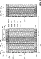
- the format of an uplink channel is shown schematically in Figure 3 .
- the uplink channel is representative of a two dimensional time-frequency resource, in which frequency is indicated along the vertical axis and time, in the form of OFDM symbols, slots, sub-frames and frames are indicated on the horizontal axis.
- the transmission can be one of a number of different bandwidths (e.g., 1.25, 5, 15, or 20 MHz).
- the uplink is broken into frames, sub-frames and slots.
- Each slot 201 (shown as slots 201 1 , 201 2 ,..., 201 19 , 201 20 , collectively slots 201) is made up of seven orthogonal frequency division multiplexed (OFDM) symbols 203.
- OFDM orthogonal frequency division multiplexed
- Two slots 201 make up a sub-frame 205 (sub-frames 205 1 , 205 2 ,..., 205 10 , collectively are sub-frames 205).
- a frame is a collection of 10 contiguous sub-frames. Because the exact details of a sub-frame 205 may vary depending upon the exact implementation, the following description is provided as an example only.
- the UE will transmit using a constant-amplitude and zero-autocorrelation (CAZAC) sequence so that more than one UE may transmit simultaneously.
- the demodulation (DM) reference symbol (RS) is placed on the fourth symbol 209 of each slot; and a control channel 211 is taken up by at least one resource block on the very outside edges of the frequency band.
- a sounding reference signal is considered to be an uplink timing reference signal transmission.
- SRS are made available at the beginning, or end, of each sub-frame 205 and is broken down into several blocks of 12 sub-carriers (not individually shown) that correspond to the same frequency bandwidth as a resource block.
- a UE may use one or all of those frequency blocks depending on the transmission bandwidth selected.
- the UE may also use every other sub-carrier in one or more multiple frequency blocks.
- the SRS is shown in the first symbol 207 of the sub-frame 205 1 and of sub-frame 201 19 .
- the transmission of SRSs is based on the time between subsequent SRS transmission by a single UE.
- Figure 3 also shows where in time and frequency that the physical uplink control channel (PUCCH), which occurs on control channel 211, is placed. Control signaling takes place in the PUCCH.
- the system implements a hybrid automatic repeat request (HARQ) acknowledgement (ACK)/negative acknowledgement (NACK) feedback.
- HARQ hybrid automatic repeat request
- ACK acknowledgement
- NACK negative acknowledgement
- An ACK or NACK is sent on the PUCCH 211 by the UE to the eNB to indicate whether a packet transmitted from the eNB was received at that UE.
- a physical uplink shared channel (PUSCH) is used to send user data.
- PUSCH physical uplink shared channel
- uplink channel is one implementation of an uplink channel. It will be appreciated that other uplink channel configurations may be used wherein an uplink timing reference signal transmission (e.g., SRS) is sent during any portion of the uplink message, not necessarily only at the beginning or end of a specified time interval (e.g., slot).
- SRS uplink timing reference signal transmission
- the network access equipment 20 In order to maintain uplink synchronization, it is desirable for the network access equipment 20 (shown in Figure 1 ) to calculate the uplink channel conditions by analyzing signals sent from the UE 10.
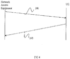
- One possible signaling diagram of signals sent between the network access equipment 20 and the UE 10 is shown in Figure 4 .
- the network access equipment 20 instructs the UE 10 when to send an uplink timing reference signal transmission (e.g., SRS), through use of an uplink timing reference signal transmission instruction message 241.
- the uplink timing reference signal transmission instruction message 241 may include any one of a variety of instructions.
- the network access equipment 20 may instruct the UE 10 via the timing reference signal transmission instruction message 241 to send the timing reference signal transmissions at a constant rate.
- the UE 10 may send the timing reference signal transmissions (e.g., SRS) in accordance with the instructions of the network access equipment 20.
- the UE may operate with discontinuous reception (DRX).
- DRX discontinuous reception
- the UE will turn its reception capability on and off in a repeating fashion.
- the network is aware of the DRX behavior and makes its transmission to the UE during periods that the reception capability is on.
- An “On” period followed by an “Off” period is a DRX cycle.
- DRX in Connected Mode will be configured by the network.
- Part of the configuration is the setting of the DRX-cycle "On" Duration, inactivity timers and HARQ timer.
- the UE will monitor the PDCCH (packet data control channel) or configured resource for the possible downlink transmissions.
- PDCCH packet data control channel
- an inactivity timer will be started.
- the UE may go back to sleep according to the DRX configuration.
- the UE will transmit the SRS (more generally an uplink timing reference signal) only during DRX "On” periods.
- the UE does not transmit SRS.
- this involves signalling the UE to transmit the SRS with a desired repetition period, and the UE transmitting the SRS for each repetition period only if it occurs during a DRX "On” period.
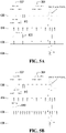
- Figure 5A shows a simple example of this where the SRS repetition period is a multiple (in this case the multiple is two) of the DRX cycle.
- the SRS is less frequent than the CQI.
- Indicated at 800 is DRX timing in which there is a DRX cycle 802 that includes a DRX "On" Duration (indicated at 804) and a DRX "Off” Duration.
- the receiver is alternately turned on for "On" periods having the DRX "On” Duration and off for "Off' periods having the DRX "Off” Duration.
- Indicated at 810 is the CQI timing.
- the CQI has a CQI period 812 that is aligned with the DRX cycle.
- the CQI is sent during the DRX "On" periods.
- Indicated at 820 is the timing of the SRS.
- the SRS has an SRS period 822.
- the SRS period 822 is double the DRX cycle 802. As such, so long as these cycle durations are in place, the SRS can be sent at the desired SRS period during DRX "On" periods.
- the UE makes its SRS transmission irrespective of DRX in certain conditions. This is particularly appropriate in order to maintain the uplink time alignment for different UE's with high velocity. This will allow an SRS period to be established that is shorter than the DRX cycle as might be the case when the DRX cycle is particularly long, and/or when the SRS period has become particularly short due to mobility of the UE.
- Figure 5B shows an example of an SRS period that is smaller than the DRX cycle. As discussed above, this situation may be more common when the UE moves to the longer DRX cycles. If UL synchronization is to be maintained even during the longer DRX cycle (for example the 640 ms DRX cycle), then the SRS needs to still be transmitted, and depending on the mobility of the UE, it may need to be transmitted at a higher frequency than the DRX cycle.
- the DRX timing 800 and CQI timing 810 are the same as in Figure 5A .
- the SRS timing 820 has an SRS period 840 that is half that of the CQI period 812, and that is shorter than the DRX cycle 802. In this case, the UE will need to turn its transmitter on outside the normal DRX "On" periods in order to be able to transmit all of the SRS transmissions.
- a resource is allocated for the UE to transmit the SRS, and this SRS resource is not released when the UE is not transmitting the SRS.
- an uplink timing alignment timer is employed.
- the timer represents the amount of time the UE is expected to be able to maintain uplink synchronization, after which it can be assumed that the UE should not transmit on the UL.
- the network transmits a timing alignment update command to the UE each time it computes new uplink timing based on received SRS from the UE to instruct the UE how to adjust its timing alignment. Once alignment has been lost, the UE will need to regain alignment when it next needs to transmit.
- the uplink timing alignment timer is run by the network. If no timing alignment update command has been sent within the period that the timer is running, then the timer will expire, and it is assumed that alignment is lost. In this event, some or all resources (e.g. CQI, SRS) allocated for UL communication are released. The network will inform the UE of when the timer expires.
- resources e.g. CQI, SRS
- the timer may run on the UE in which case the network may inform the UE of the timer value.
- the timer is reset by the reception of a timing alignment (TA) update command.
- TA timing alignment
- the CQI and SRS are both transmitted during DRX "On" Durations, although not necessarily with the same frequency.
- transmission of SRS and CQI is configured to be in the same sub-frame whenever feasible.
- An example of this is shown in Figure 3 where the CQI 213 is sent in the same sub-frame 201 1 as the SRS 207.
- this should be possible for every SRS transmission since the SRS period is twice that of the CQI period.
- the SRS and CQI can be transmitted in the same sub-frame for every second SRS transmission.
- the CQI is also only transmitted during DRX "On” durations.
- the CQI is allowed to be transmitted during DRX "On” durations and can be transmitted during periods that the transmitter has been turned on irrespective of DRX "On” durations for the purpose of transmitting SRS.
- the DTX (discontinuous transmission) periods do not necessarily align with the DRX periods. Once the SRS and CQI have been transmitted, the transmitter can be turned off, even though the receiver may still be on.
- Figures 5A and 5B also each show timing of scheduling requests (SR), generally indicated at 830.
- a scheduling request is an indication sent by the UE to the base station to request the UL resource.
- the UE transmits scheduling requests only during DRX "On" periods.
- the UE transmits scheduling requests during a sub-frame that the transmitter is already on to transmit the CQI, the SRS or both. This can occur through network configuration of the UE, or at the initiative of the UE. Data may be sent from the UE during the DRX "On" period.
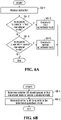
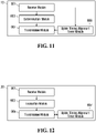
- FIG. 6A illustrates a flow chart of a specific example of such a method for SRS transmission in a UE 10.
- the method of Figure 6A might be executed continuously, or when there is a change in SRS period and/or DRX cycle for example.
- the SRS period may change as a function of mobility of the UE, whereas the DRX cycle may change as a function of level of communications activity involving the UE.
- the UE receives an instruction from the network. If the instruction is to operate in the first operational mode (yes path, block 6A-2), the UE operates in the first operational mode at block 6A-3. If there are no instructions to operate in the first operational mode (no path, block 6A-2), a subsequent decision involves determining whether there is an instruction to operate in the second operational mode. If the instruction is to operate in the second operational mode (yes path, block 6A-4), the UE operates in the second operational mode at block 6A-5. More generally, in a first operational mode, the UE executes block 6A-3 and in a second operational mode, the UE executes block 6A-5. The conditions for executing the first or second operational mode may be as described above, or may be different. In some implementations, only the first operational mode is provided, or only the second operational mode is provided.
- FIG. 6B A flowchart of such an embodiment from the network perspective is shown in Figure 6B .
- the network determines whether the UE should operate in the first operational mode or the second operational mode. This can be done as a function of mobility of the UE and/or channel utilization to name a few examples.
- the network sends an instruction to the UE to operate in the determined operational mode.
- the UE 10 comprises a processor capable of performing the above process.
- the different functions have been broken out into different modules. These modules may be implemented separately or together. Further, these modules may be implemented in hardware, software, or some combination. Finally, these modules may reside in different portions of the UE memory.
- the UE processor comprises a receive module 801, a determination module 803, and a transmission module 807.
- the receive module 801 receives a message or messages indicating an operational mode for SRS transmission.
- the determination module 803 determines the manner of transmitting the SRS having regard to the message.
- the determination module informs the transmission module 807 to send the SRS in accordance with the determination made by the determination module 803.
- the UE runs an uplink timing alignment timer as described above in which case the UE further comprises an uplink timing alignment timer module 809.
- the timer is reset upon receipt of a timing alignment update message by the receive module 801. If the timer expires, the UE releases the resource used for SRS transmission by the transmission module 807.
- the receive module 801 of the UE receives an instruction from the network that indicates timing has been lost in which case the UE releases the resource used for SRS transmission.
- the network access equipment 20 also comprises a processor.
- the processor comprises a receive module 901, an evaluation module 903 and a transmission module 905. Again, these modules are defined for simplicity, and may be executed in software, hardware, firmware, or both. Additionally, these modules may be stored in the same or different memories.
- the receiver module 901 receives SRS messages, CQI and other signals from the UE.
- the evaluation module 903 evaluates an appropriate DRX period and a desired SRS period. This may for example be done having regard to the activity of the UE, the mobility of the UE, and/or activity of the UE.
- the evaluation module determines an appropriate SRS transmission behavior having regard to the DRX behavior and SRS repetition period and instructs the transmission module 905 to signal this to the UE.
- the network runs an uplink timing alignment timer as described above in which case the processor further comprises an uplink timing alignment timer module 907.
- the timer is reset upon transmission of a timing alignment update message by the transmission module 905.
- the network sends an instruction to the UE to release the resource used for SRS transmission, and the network also releases the resource used for SRS transmission.
- the network released the resource used for SRS transmission without sending a message to the UE.
- the network may have previously sent a timer value to the UE. Because the UE may have used that timer value to start its own uplink alignment timer, the UE would not need a message from the network informing the UE that the timer had expired and the SRS resource is to be released.
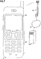
- FIG. 7 illustrates a wireless communications system including an embodiment of the UE 10.
- the UE 10 is operable for implementing aspects of the disclosure, but the disclosure should not be limited to these implementations.
- the UE 10 may take various forms including a wireless handset, a pager, a personal digital assistant (PDA), a portable computer, a tablet computer, or a laptop computer. Many suitable devices combine some or all of these functions.
- the UE 10 is not a general purpose computing device like a portable, laptop or tablet computer, but rather is a special-purpose communications device such as a mobile phone, a wireless handset, a pager, a PDA, or a telecommunications device installed in a vehicle.
- the UE 10 may be a portable, laptop or other computing device.
- the UE 10 may support specialized activities such as gaming, inventory control, job control, and/or task management functions, and so on.
- the UE 10 includes a display 402.
- the UE 10 also includes a touch-sensitive surface, a keyboard or other input keys generally referred as 404 for input by a user.
- the keyboard may be a full or reduced alphanumeric keyboard such as QWERTY, Dvorak, AZERTY, and sequential types, or a traditional numeric keypad with alphabet letters associated with a telephone keypad.
- the input keys may include a track wheel, an exit or escape key, a trackball, and other navigational or functional keys, which may be inwardly depressed to provide further input function.
- the UE 10 may present options for the user to select, controls for the user to actuate, and/or cursors or other indicators for the user to direct.
- the UE 10 may further accept data entry from the user, including numbers to dial or various parameter values for configuring the operation of the UE 10.
- the UE 10 may further execute one or more software or firmware applications in response to user commands. These applications may configure the UE 10 to perform various customized functions in response to user interaction. Additionally, the UE 10 may be programmed and/or configured over-the-air, for example from a wireless base station, a wireless access point, or a peer UE 10.
- the various applications executable by the UE 10 are a web browser, which enables the display 402 to show a web page.
- the web page may be obtained via wireless communications with a wireless network access node, a cell tower, a peer UE 10, or any other wireless communication network or system 400.
- the network 400 is coupled to a wired network 408, such as the Internet.
- the UE 10 has access to information on various servers, such as a server 410.
- the server 410 may provide content that may be shown on the display 402.
- the UE 10 may access the network 400 through a peer UE 10 acting as an intermediary, in a relay type or hop type of connection.
- FIG 8 shows a block diagram of the UE 10. While a variety of known components of UEs 10 are depicted, in an embodiment a subset of the listed components and/or additional components not listed may be included in the UE 10.
- the UE 10 includes a digital signal processor (DSP) 502 and a memory 504.
- DSP digital signal processor
- the UE 10 may further include an antenna and front end unit 506, a radio frequency (RF) transceiver 508, an analog baseband processing unit 510, a microphone 512, an earpiece speaker 514, a headset port 516, an input/output interface 518, a removable memory card 520, a universal serial bus (USB) port 522, a short range wireless communication sub-system 524, an alert 526, a keypad 528, a liquid crystal display (LCD), which may include a touch sensitive surface 530, an LCD controller 532, a charge-coupled device (CCD) camera 534, a camera controller 536, and a global positioning system (GPS) sensor 538.
- the UE 10 may include another kind of display that does not provide a touch sensitive screen.
- the DSP 502 may communicate directly with the memory 504 without passing through the input/output interface 518.
- the DSP 502 or some other form of controller or central processing unit operates to control the various components of the UE 10 in accordance with embedded software or firmware stored in memory 504 or stored in memory contained within the DSP 502 itself.
- the DSP 502 may execute other applications stored in the memory 504 or made available via information carrier media such as portable data storage media like the removable memory card 520 or via wired or wireless network communications.
- the application software may comprise a compiled set of machine-readable instructions that configure the DSP 502 to provide the desired functionality, or the application software may be high-level software instructions to be processed by an interpreter or compiler to indirectly configure the DSP 502.
- the antenna and front end unit 506 may be provided to convert between wireless signals and electrical signals, enabling the UE 10 to send and receive information from a cellular network or some other available wireless communications network or from a peer UE 10.
- the antenna and front end unit 506 may include multiple antennas to support beam forming and/or multiple input multiple output (MIMO) operations.
- MIMO operations may provide spatial diversity which can be used to overcome difficult channel conditions and/or increase channel throughput.
- the antenna and front end unit 506 may include antenna tuning and/or impedance matching components, RF power amplifiers, and/or low noise amplifiers.
- the RF transceiver 508 provides frequency shifting, converting received RF signals to baseband and converting baseband transmit signals to RF.
- a radio transceiver or RF transceiver may be understood to include other signal processing functionality such as modulation/demodulation, coding/decoding, interleaving/deinterleaving, spreading/despreading, inverse fast Fourier transforming (IFFT)/fast Fourier transforming (FFT), cyclic prefix appending/removal, and other signal processing functions.
- IFFT inverse fast Fourier transforming
- FFT fast Fourier transforming
- cyclic prefix appending/removal and other signal processing functions.
- the description here separates the description of this signal processing from the RF and/or radio stage and conceptually allocates that signal processing to the analog baseband processing unit 510 and/or the DSP 502 or other central processing unit.
- the RF Transceiver 508, portions of the Antenna and Front End 506, and the analog baseband processing unit 510
- the analog baseband processing unit 510 may provide various analog processing of inputs and outputs, for example analog processing of inputs from the microphone 512 and the headset 516 and outputs to the earpiece 514 and the headset 516.
- the analog baseband processing unit 510 may have ports for connecting to the built-in microphone 512 and the earpiece speaker 514 that enable the UE 10 to be used as a cell phone.
- the analog baseband processing unit 510 may further include a port for connecting to a headset or other hands-free microphone and speaker configuration.
- the analog baseband processing unit 510 may provide digital-to-analog conversion in one signal direction and analog-to-digital conversion in the opposing signal direction.
- at least some of the functionality of the analog baseband processing unit 510 may be provided by digital processing components, for example by the DSP 502 or by other central processing units.
- the DSP 502 may perform modulation/demodulation, coding/decoding, interleaving/deinterleaving, spreading/despreading, inverse fast Fourier transforming (IFFT)/fast Fourier transforming (FFT), cyclic prefix appending/removal, and other signal processing functions associated with wireless communications.
- IFFT inverse fast Fourier transforming
- FFT fast Fourier transforming
- cyclic prefix appending/removal and other signal processing functions associated with wireless communications.
- CDMA code division multiple access
- the DSP 502 may perform modulation, coding, interleaving, inverse fast Fourier transforming, and cyclic prefix appending, and for a receiver function the DSP 502 may perform cyclic prefix removal, fast Fourier transforming, deinterleaving, decoding, and demodulation.
- OFDMA orthogonal frequency division multiplex access
- the DSP 502 may communicate with a wireless network via the analog baseband processing unit 510.
- the communication may provide Internet connectivity, enabling a user to gain access to content on the Internet and to send and receive e-mail or text messages.
- the input/output interface 518 interconnects the DSP 502 and various memories and interfaces.
- the memory 504 and the removable memory card 520 may provide software and data to configure the operation of the DSP 502.
- the interfaces may be the USB interface 522 and the short range wireless communication sub-system 524.
- the USB interface 522 may be used to charge the UE 10 and may also enable the UE 10 to function as a peripheral device to exchange information with a personal computer or other computer system.
- the short range wireless communication sub-system 524 may include an infrared port, a Bluetooth interface, an IEEE 802.11 compliant wireless interface, or any other short range wireless communication sub-system, which may enable the UE 10 to communicate wirelessly with other nearby mobile devices and/or wireless base stations.
- the input/output interface 518 may further connect the DSP 502 to the alert 526 that, when triggered, causes the UE 10 to provide a notice to the user, for example, by ringing, playing a melody, or vibrating.
- the alert 526 may serve as a mechanism for alerting the user to any of various events such as an incoming call, a new text message, and an appointment reminder by silently vibrating, or by playing a specific pre-assigned melody for a particular caller.
- the keypad 528 couples to the DSP 502 via the interface 518 to provide one mechanism for the user to make selections, enter information, and otherwise provide input to the UE 10.
- the keyboard 528 may be a full or reduced alphanumeric keyboard such as QWERTY, Dvorak, AZERTY and sequential types, or a traditional numeric keypad with alphabet letters associated with a telephone keypad.
- the input keys may include a track wheel, an exit or escape key, a trackball, and other navigational or functional keys, which may be inwardly depressed to provide further input function.
- Another input mechanism may be the LCD 530, which may include touch screen capability and also display text and/or graphics to the user.
- the LCD controller 532 couples the DSP 502 to the LCD 530.
- the CCD camera 534 if equipped, enables the UE 10 to take digital pictures.
- the DSP 502 communicates with the CCD camera 534 via the camera controller 536.
- a camera operating according to a technology other than Charge Coupled Device cameras may be employed.
- the GPS sensor 538 is coupled to the DSP 502 to decode global positioning system signals, thereby enabling the UE 10 to determine its position.
- Various other peripherals may also be included to provide additional functions, e.g., radio and television reception.
- FIG 9 illustrates a software environment 602 that may be implemented by the DSP 502.
- the DSP 502 executes operating system drivers 604 that provide a platform from which the rest of the software operates.
- the operating system drivers 604 provide drivers for the wireless device hardware with standardized interfaces that are accessible to application software.
- the operating system drivers 604 include application management services ("AMS") 606 that transfer control between applications running on the UE 10.
- AMS application management services
- Also shown in Figure 9 are a web browser application 608, a media player application 610, and Java applets 612.
- the web browser application 608 configures the UE 10 to operate as a web browser, allowing a user to enter information into forms and select links to retrieve and view web pages.
- the media player application 610 configures the UE 10 to retrieve and play audio or audiovisual media.
- the Java applets 612 configure the UE 10 to provide games, utilities, and other functionality.
- a component 614 might provide functionality related to the present disclosure.
- the UEs 10, ENBs 20, and central control 110 of Figure 1 and other components that might be associated with the cells 102 may include any general-purpose computer with sufficient processing power, memory resources, and network throughput capability to handle the necessary workload placed upon it.
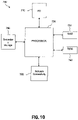
- Figure 10 illustrates a typical, general-purpose computer system 700 that may be suitable for implementing one or more embodiments disclosed herein.
- the computer system 700 includes a processor 720 (which may be referred to as a central processor unit or CPU) that is in communication with memory devices including secondary storage 750, read only memory (ROM) 740, random access memory (RAM) 730, input/output (I/O) devices 710, and network connectivity devices 760.
- the processor may be implemented as one or more CPU chips.
- the secondary storage 750 is typically comprised of one or more disk drives or tape drives and is used for non-volatile storage of data and as an over-flow data storage device if RAM 730 is not large enough to hold all working data. Secondary storage 750 may be used to store programs which are loaded into RAM 730 when such programs are selected for execution.
- the ROM 740 is used to store instructions and perhaps data which are read during program execution. ROM 740 is a non-volatile memory device which typically has a small memory capacity relative to the larger memory capacity of secondary storage.
- the RAM 730 is used to store volatile data and perhaps to store instructions. Access to both ROM 740 and RAM 730 is typically faster than to secondary storage 750.
- I/O devices 710 may include printers, video monitors, liquid crystal displays (LCDs), touch screen displays, keyboards, keypads, switches, dials, mice, track balls, voice recognizers, card readers, paper tape readers, or other well-known input devices.
- LCDs liquid crystal displays
- touch screen displays keyboards, keypads, switches, dials, mice, track balls, voice recognizers, card readers, paper tape readers, or other well-known input devices.
- the network connectivity devices 760 may take the form of modems, modem banks, ethernet cards, universal serial bus (USB) interface cards, serial interfaces, token ring cards, fiber distributed data interface (FDDI) cards, wireless local area network (WLAN) cards, radio transceiver cards such as code division multiple access (CDMA) and/or global system for mobile communications (GSM) radio transceiver cards, and other well-known network devices.
- These network connectivity 760 devices may enable the processor 720 to communicate with an Internet or one or more intranets. With such a network connection, it is contemplated that the processor 720 might receive information from the network, or might output information to the network in the course of performing the above-described method steps. Such information, which is often represented as a sequence of instructions to be executed using processor 720, may be received from and outputted to the network, for example, in the form of a computer data signal embodied in a carrier wave.
- Such information may be received from and outputted to the network, for example, in the form of a computer data baseband signal or signal embodied in a carrier wave.
- the baseband signal or signal embodied in the carrier wave generated by the network connectivity 760 devices may propagate in or on the surface of electrical conductors, in coaxial cables, in waveguides, in optical media, for example optical fiber, or in the air or free space.
- the information contained in the baseband signal or signal embedded in the carrier wave may be ordered according to different sequences, as may be desirable for either processing or generating the information or transmitting or receiving the information.
- the baseband signal or signal embedded in the carrier wave, or other types of signals currently used or hereafter developed, referred to herein as the transmission medium may be generated according to several methods well known to one skilled in the art.
- the processor 720 executes instructions, codes, computer programs, scripts which it accesses from hard disk, floppy disk, optical disk (these various disk-based systems may all be considered secondary storage 750), ROM 740, RAM 730, or the network connectivity devices 760. While only one processor 720 is shown, multiple processors may be present. Thus, while instructions may be discussed as executed by a processor, the instructions may be executed simultaneously, serially, or otherwise executed by one or multiple processors.
- Radio Layer 1 and Radio Layer 2 are standards related to Radio Layer 1 and Radio Layer 2, respectively.
- Radio Layer 1 generally pertains to, but is not limited to, the physical layer of the radio interface for UE, UTRAN (UMTS Terrestrial Radio Access Network), Evolved UTRAN, and beyond and may cover both frequency divisional duplex (FDD) and time divisional duplex (TDD) modes of radio interface
- Radio Layer 2 generally pertains to, but is not limited to, radio interface architecture and protocols such as media access control (MAC), radio link control (RLC) and packet data convergence protocol (PDCP), specification of the Radio Resource Control protocol, and strategies of Radio Resource Management and the services provided by the physical layer to the upper layers).
- MAC media access control
- RLC radio link control
- PDCP packet data convergence protocol
- SRS sounding reference signals
- SR scheduling request
- SRI scheduling indicators
- SRS Downlink Reference Signal
- DRX in Connected Mode will be configured by the eNB.
- Part of the configuration is the setting of the DRX-cycle "On" Duration, inactivity timers and HARQ timer.
- UE will monitor the PDCCH or configured resource for the possible downlink transmissions.
- an inactivity timer will be started.
- UE may go back to sleep according to the configurations.
- a length of long DRX cycle is a determiner in how to allow the UE to move into an unsynchronized state. It is conceivable that a DRX cycle greater than 1 second could lead to loss of UL synchronization. At such a point, all SRS and CQI transmissions on the UL should be terminated and the UE should access the random access channel (RACH) whenever data needs to flow in the UL.
- RACH random access channel
- mobility has a direct impact on UL synchronization loss. If the unsynchronized state has not been entered, the SRS transmission must continue as needed. Under modest mobility conditions (e.g. 30 kilometers/hour), the SRS period may be on the order of 50 ms. This is less than several of the shorter DRX cycles. Synchronization is to be maintained if any uplink transmissions are to take place.
- the UE will transmit the SRS during the appropriate "On" Duration. In the "Off" Duration, the UE may not transmit SRS. Furthermore, to simplify the procedure by avoiding frequent reassignment or release, the SRS resource should not be released when the UE is not transmitting the SRS. In some embodiments, the SRS resource is only released when an uplink timing alignment timer expires.
- the UE transmits the SRS during the DRX "On" Duration, and SRS transmissions may be stopped during the off duration.
- the resource for the SRS is maintained during the DRX and released only when the uplink timing alignment timer has expired.
- transmission of SRS and CQI occur in the same sub-frame whenever feasible.
- the eNB is enabled to configure the UE for the SRS transmission irrespective of DRX in certain conditions.
- transmission of SRS and CQI is in the same sub-frame whenever feasible to save UE's battery power.
- the eNB configures the UE to transmit SRS irrespective of the DRX.
- Figure 5A shows the case when the SRS period is less frequent than CQI.
- Figure 5B shows the opposite case.
- the eNB selects an SRS transmission periodicity that is smaller than the DRX cycle. This situation will be more common when the UE moves to the longer DRX cycles. If UL synchronization must be maintained even during the longer DRX cycle, for example 640 ms or more, then the SRS is transmitted.
- methods and devices described herein are for use in long term evolution (LTE) networks.
- LTE long term evolution
- the devices and methods described herein are not intended to be limited to only LTE networks.
- the methods and devices described herein are for use with other types of communication networks.
Landscapes
- Engineering & Computer Science (AREA)
- Signal Processing (AREA)
- Computer Networks & Wireless Communication (AREA)
- Power Engineering (AREA)
- Mobile Radio Communication Systems (AREA)
- Synchronisation In Digital Transmission Systems (AREA)
Claims (5)
- Procédé réalisé dans un équipement d'accès réseau comprenant :l'envoi d'informations de commande à un équipement utilisateur, UE, comprenant un récepteur, les informations de commande étant exploitables à leur exécution pour configurer l'UE afin de commander le récepteur pour établir une durée de temps actif de réception discontinue, DRX, en mode connecté ;l'envoi d'informations de commande à l'UE pour configurer l'équipement utilisateur afin de déterminer des sous-trames de signal de référence de sondage, SRS, de liaison montante en fonction d'une période de répétition de SRS ; etla tenue à jour d'une configuration de ressource de SRS pour l'équipement utilisateur lorsqu'il n'est pas dans ledit temps actif de DRX et qu'il ne reçoit pas de SRS de liaison montante depuis l'UE, la configuration de ressource de SRS étant associée à une ressource temps-fréquence, ladite configuration de ressource de SRS tenue à jour étant libérée à l'expiration d'une minuterie d'alignement de synchronisation de liaison montante configurée par le réseau, et le SRS de liaison montante étant reçu par l'équipement d'accès réseau après son émission par l'UE uniquement durant le temps actif de DRX.
- Procédé selon la revendication 1, dans lequel l'équipement d'accès réseau fait partie d'un réseau d'évolution à long terme.
- Procédé selon n'importe quelle revendication précédente, dans lequel le début du temps actif de DRX se répète périodiquement.
- Equipement d'accès réseau comprenant un processeur configuré pour réaliser le procédé selon n'importe quelle revendication précédente.
- Support lisible par ordinateur sur lequel sont stockées des instructions exécutables par ordinateur pour mettre en œuvre le procédé selon l'une quelconque des revendications 1 à 3.
Priority Applications (4)
| Application Number | Priority Date | Filing Date | Title |
|---|---|---|---|
| EP19203425.4A EP3654536A1 (fr) | 2008-02-01 | 2009-01-30 | Système et procédé de synchronisation temporelle de liaison montante en conjonction avec une réception discontinue |
| EP19203426.2A EP3661067A1 (fr) | 2008-02-01 | 2009-01-30 | Système et procédé de synchronisation temporelle de liaison montante en conjonction avec une réception discontinue |
| PL15194137.4T PL3002881T5 (pl) | 2008-02-01 | 2009-01-30 | Układ i sposób synchronizacji taktowania dla łącza w górę w połączeniu z nieciągłym odbiorem |
| EP19203424.7A EP3654535A1 (fr) | 2008-02-01 | 2009-01-30 | Système et procédé de synchronisation temporelle de liaison montante en conjonction avec une réception discontinue |
Applications Claiming Priority (4)
| Application Number | Priority Date | Filing Date | Title |
|---|---|---|---|
| US2548508P | 2008-02-01 | 2008-02-01 | |
| EP14167577.7A EP2806568B1 (fr) | 2008-02-01 | 2009-01-30 | Système et procédé de synchronisation temporelle de liaison montante en conjonction avec une réception discontinue |
| EP09708667.2A EP2248270B1 (fr) | 2008-02-01 | 2009-01-30 | Système et procédé permettant de procéder à une synchronisation de liaison montante en association avec une réception discontinue |
| PCT/US2009/032591 WO2009099931A1 (fr) | 2008-02-01 | 2009-01-30 | Système et procédé permettant de procéder à une synchronisation de liaison montante en association avec une réception discontinue |
Related Parent Applications (3)
| Application Number | Title | Priority Date | Filing Date |
|---|---|---|---|
| EP14167577.7A Division EP2806568B1 (fr) | 2008-02-01 | 2009-01-30 | Système et procédé de synchronisation temporelle de liaison montante en conjonction avec une réception discontinue |
| EP14167577.7A Division-Into EP2806568B1 (fr) | 2008-02-01 | 2009-01-30 | Système et procédé de synchronisation temporelle de liaison montante en conjonction avec une réception discontinue |
| EP09708667.2A Division EP2248270B1 (fr) | 2008-02-01 | 2009-01-30 | Système et procédé permettant de procéder à une synchronisation de liaison montante en association avec une réception discontinue |
Related Child Applications (6)
| Application Number | Title | Priority Date | Filing Date |
|---|---|---|---|
| EP19203425.4A Division-Into EP3654536A1 (fr) | 2008-02-01 | 2009-01-30 | Système et procédé de synchronisation temporelle de liaison montante en conjonction avec une réception discontinue |
| EP19203425.4A Division EP3654536A1 (fr) | 2008-02-01 | 2009-01-30 | Système et procédé de synchronisation temporelle de liaison montante en conjonction avec une réception discontinue |
| EP19203426.2A Division EP3661067A1 (fr) | 2008-02-01 | 2009-01-30 | Système et procédé de synchronisation temporelle de liaison montante en conjonction avec une réception discontinue |
| EP19203426.2A Division-Into EP3661067A1 (fr) | 2008-02-01 | 2009-01-30 | Système et procédé de synchronisation temporelle de liaison montante en conjonction avec une réception discontinue |
| EP19203424.7A Division-Into EP3654535A1 (fr) | 2008-02-01 | 2009-01-30 | Système et procédé de synchronisation temporelle de liaison montante en conjonction avec une réception discontinue |
| EP19203424.7A Division EP3654535A1 (fr) | 2008-02-01 | 2009-01-30 | Système et procédé de synchronisation temporelle de liaison montante en conjonction avec une réception discontinue |
Publications (3)
| Publication Number | Publication Date |
|---|---|
| EP3002881A1 EP3002881A1 (fr) | 2016-04-06 |
| EP3002881B1 EP3002881B1 (fr) | 2019-10-16 |
| EP3002881B2 true EP3002881B2 (fr) | 2022-08-03 |
Family
ID=40600162
Family Applications (6)
| Application Number | Title | Priority Date | Filing Date |
|---|---|---|---|
| EP15194137.4A Active EP3002881B2 (fr) | 2008-02-01 | 2009-01-30 | Système et procédé de synchronisation temporelle de liaison montante en conjonction avec une réception discontinue |
| EP19203424.7A Pending EP3654535A1 (fr) | 2008-02-01 | 2009-01-30 | Système et procédé de synchronisation temporelle de liaison montante en conjonction avec une réception discontinue |
| EP19203425.4A Pending EP3654536A1 (fr) | 2008-02-01 | 2009-01-30 | Système et procédé de synchronisation temporelle de liaison montante en conjonction avec une réception discontinue |
| EP09708667.2A Active EP2248270B1 (fr) | 2008-02-01 | 2009-01-30 | Système et procédé permettant de procéder à une synchronisation de liaison montante en association avec une réception discontinue |
| EP19203426.2A Withdrawn EP3661067A1 (fr) | 2008-02-01 | 2009-01-30 | Système et procédé de synchronisation temporelle de liaison montante en conjonction avec une réception discontinue |
| EP14167577.7A Active EP2806568B1 (fr) | 2008-02-01 | 2009-01-30 | Système et procédé de synchronisation temporelle de liaison montante en conjonction avec une réception discontinue |
Family Applications After (5)
| Application Number | Title | Priority Date | Filing Date |
|---|---|---|---|
| EP19203424.7A Pending EP3654535A1 (fr) | 2008-02-01 | 2009-01-30 | Système et procédé de synchronisation temporelle de liaison montante en conjonction avec une réception discontinue |
| EP19203425.4A Pending EP3654536A1 (fr) | 2008-02-01 | 2009-01-30 | Système et procédé de synchronisation temporelle de liaison montante en conjonction avec une réception discontinue |
| EP09708667.2A Active EP2248270B1 (fr) | 2008-02-01 | 2009-01-30 | Système et procédé permettant de procéder à une synchronisation de liaison montante en association avec une réception discontinue |
| EP19203426.2A Withdrawn EP3661067A1 (fr) | 2008-02-01 | 2009-01-30 | Système et procédé de synchronisation temporelle de liaison montante en conjonction avec une réception discontinue |
| EP14167577.7A Active EP2806568B1 (fr) | 2008-02-01 | 2009-01-30 | Système et procédé de synchronisation temporelle de liaison montante en conjonction avec une réception discontinue |
Country Status (18)
| Country | Link |
|---|---|
| US (19) | US8634361B2 (fr) |
| EP (6) | EP3002881B2 (fr) |
| JP (2) | JP2011514723A (fr) |
| KR (2) | KR101184535B1 (fr) |
| CN (1) | CN101971509B (fr) |
| AU (1) | AU2009212717B2 (fr) |
| BR (3) | BR122017024419B1 (fr) |
| CA (1) | CA2713870C (fr) |
| DK (1) | DK3002881T3 (fr) |
| ES (3) | ES2538812T3 (fr) |
| FI (1) | FI3002881T5 (fr) |
| HK (3) | HK1204165A1 (fr) |
| HU (1) | HUE048705T2 (fr) |
| MX (1) | MX2010008477A (fr) |
| PL (1) | PL3002881T5 (fr) |
| PT (1) | PT3002881T (fr) |
| SG (1) | SG188107A1 (fr) |
| WO (1) | WO2009099931A1 (fr) |
Families Citing this family (49)
| Publication number | Priority date | Publication date | Assignee | Title |
|---|---|---|---|---|
| EP3002881B2 (fr) * | 2008-02-01 | 2022-08-03 | Guangdong Oppo Mobile Telecommunications Corp., Ltd. | Système et procédé de synchronisation temporelle de liaison montante en conjonction avec une réception discontinue |
| US8249004B2 (en) * | 2008-03-14 | 2012-08-21 | Interdigital Patent Holdings, Inc. | Coordinated uplink transmission in LTE DRX operations for a wireless transmit receive unit |
| CN101572896B (zh) * | 2008-04-29 | 2011-01-26 | 大唐移动通信设备有限公司 | 一种配置上行探测参考信号的方法和装置 |
| KR101468742B1 (ko) * | 2008-05-06 | 2014-12-04 | 엘지전자 주식회사 | 무선통신 시스템에서 데이터 전송 방법 |
| WO2010018819A1 (fr) * | 2008-08-11 | 2010-02-18 | 株式会社エヌ・ティ・ティ・ドコモ | Dispositif de station de base et méthode de contrôle de communications |
| JP5331593B2 (ja) * | 2009-06-25 | 2013-10-30 | 京セラ株式会社 | 無線基地局及びリソース割り当て方法 |
| JP5608178B2 (ja) * | 2010-01-14 | 2014-10-15 | パナソニック インテレクチュアル プロパティ コーポレーション オブ アメリカ | 端末装置、通信装置及び通信方法 |
| KR101807874B1 (ko) | 2010-03-05 | 2017-12-12 | 엘지전자 주식회사 | 무선 통신 시스템에서 비주기적 사운딩 참조 신호 전송 방법 및 장치 |
| JP5423505B2 (ja) | 2010-03-17 | 2014-02-19 | 富士通株式会社 | 無線基地局及び通信方法 |
| US20110292823A1 (en) * | 2010-05-27 | 2011-12-01 | Qualcomm Incorporated | Sounding reference signal (srs) in heterogeneous network (hetnet) with time division multiplexing (tdm) partitioning |
| WO2012000547A1 (fr) * | 2010-06-30 | 2012-01-05 | Nokia Siemens Networks Oy | Planification de terminaux d'utilisateur dans un réseau de communication |
| US9867165B2 (en) * | 2010-07-19 | 2018-01-09 | Lg Electronics Inc. | Method and device for transmitting a feedback signal in a multi-node system |
| US8937893B1 (en) * | 2010-09-13 | 2015-01-20 | Marvell International Ltd. | Method and apparatus for delaying wireless message transmission for saving power |
| JP5808178B2 (ja) * | 2010-10-01 | 2015-11-10 | キヤノン株式会社 | 通信装置、通信装置の制御方法及びプログラム |
| CA2823966A1 (fr) * | 2011-01-07 | 2012-07-12 | Fujitsu Limited | Procede, noeud b evolue et equipement utilisateur pour declencher un signal de reference de sondageriodique aperiodique |
| US9161371B2 (en) * | 2011-07-21 | 2015-10-13 | Qualcomm Incorporated | Power optimization using scheduling request delay |
| US8842641B2 (en) * | 2011-08-12 | 2014-09-23 | Telefonaktiebolaget L M Ericsson (Publ) | RAKE resource multiplexing for enhanced uplink data services |
| US20130044659A1 (en) | 2011-08-16 | 2013-02-21 | Renesas Mobile Corporation | Wireless Devices and Base Stations and Methods of Operating |
| GB2483752A (en) * | 2011-08-16 | 2012-03-21 | Renesas Mobile Corp | Extended drx time periods for machine-type communications using an absolute timing reference |
| WO2013066044A1 (fr) * | 2011-10-31 | 2013-05-10 | 엘지전자 주식회사 | Procédé pour transmettre un signal de commande de liaison montante, équipement d'utilisateur, procédé pour recevoir un signal de liaison montante, et station de base |
| WO2013079104A1 (fr) * | 2011-11-30 | 2013-06-06 | Nokia Siemens Networks Oy | Gestion d'un état d'un dispositif |
| EP2807893A1 (fr) * | 2012-01-29 | 2014-12-03 | Alcatel Lucent | Libération de connexion de commande de ressources radio pour dispositifs utilisateurs en dehors du temps de liaison montante |
| JP6001100B2 (ja) * | 2012-03-15 | 2016-10-05 | ノキア ソリューションズ アンド ネットワークス オサケユキチュア | キャリア関連の基準信号送信の構成 |
| US9198071B2 (en) * | 2012-03-19 | 2015-11-24 | Qualcomm Incorporated | Channel state information reference signal configuring and reporting for a coordinated multi-point transmission scheme |
| CN103517344B (zh) * | 2012-06-20 | 2016-06-29 | 普天信息技术研究院有限公司 | 上行侦听参考信号的传输方法 |
| US10206244B2 (en) | 2012-07-06 | 2019-02-12 | Samsung Electronics Co., Ltd | Method and apparatus for determining TDD UL-DL configuration applicable for radio frames |
| JP6152252B2 (ja) * | 2012-07-20 | 2017-06-21 | 株式会社Nttドコモ | 移動局 |
| US8755318B2 (en) | 2012-09-05 | 2014-06-17 | Apple Inc. | Synchronizing uplink and downlink transmissions in a wireless device |
| JP5986475B2 (ja) * | 2012-10-10 | 2016-09-06 | 京セラ株式会社 | 携帯通信システム |
| US9497047B2 (en) | 2013-07-02 | 2016-11-15 | Samsung Electronics Co., Ltd. | Methods and apparatus for sounding channel operation in millimeter wave communication systems |
| US10187857B2 (en) * | 2013-09-27 | 2019-01-22 | Apple Inc. | System and method for selective prevention of transmitting a scheduling request |
| JP2015122578A (ja) | 2013-12-20 | 2015-07-02 | 株式会社Nttドコモ | ユーザ装置、及び信号送信制御方法 |
| US11743897B2 (en) | 2013-12-20 | 2023-08-29 | Qualcomm Incorporated | Techniques for configuring uplink channels in unlicensed radio frequency spectrum bands |
| CN104936223B (zh) * | 2014-03-21 | 2019-05-24 | 上海诺基亚贝尔股份有限公司 | 对关闭状态中的小小区进行测量增强以实施双连接的方法 |
| WO2016136958A1 (fr) * | 2015-02-27 | 2016-09-01 | 京セラ株式会社 | Terminal sans fil et processeur |
| EP3641422B1 (fr) * | 2015-11-30 | 2021-09-01 | Telefonaktiebolaget LM Ericsson (publ) | Procede de redefinition d'un temporisateur d'alignement temporel d'un reseau de communication sans fil, equipement d'utilisateur et noeud de reseau correspondants |
| US10097336B2 (en) | 2015-11-30 | 2018-10-09 | Qualcomm Incorporated | Uplink (UL) frequency-division duplex (FDD) subframe |
| US10122559B2 (en) * | 2016-03-21 | 2018-11-06 | Qualcomm Incorporated | Uplink channel quality measurement using a subframe with high-intensity reference signal bursts |
| US10555297B2 (en) | 2016-03-31 | 2020-02-04 | Telefonaktiebolaget Lm Ericsson (Publ) | Uplink transmission timing control |
| US10541802B2 (en) | 2016-03-31 | 2020-01-21 | Telefonaktiebolaget Lm Ericsson (Publ) | Application of timing advance command in wireless communication device in enhanced coverage mode |
| US10674418B2 (en) * | 2016-08-10 | 2020-06-02 | Sony Corporation | Terminal device, telecommunications networks and methods |
| KR20180035638A (ko) | 2016-09-29 | 2018-04-06 | 삼성전자주식회사 | RRC Inactive 및 active 상태에서 data 전송 결정 및 방법 및 장치 |
| CN108365936B (zh) * | 2017-01-26 | 2020-10-27 | 华为技术有限公司 | 一种通信方法,装置及系统 |
| US10750569B2 (en) | 2017-03-03 | 2020-08-18 | Qualcomm Incorporated | Beam management for connected mode discontinuous reception operation |
| US10187131B2 (en) | 2017-06-09 | 2019-01-22 | At&T Intellectual Property I, L.P. | Facilitation of rank and precoding matrix indication determinations for multiple antenna systems with aperiodic channel state information reporting in 5G or other next generation networks |
| CN109151969B (zh) * | 2017-06-16 | 2022-04-05 | 中兴通讯股份有限公司 | 发送功率的确定方法及装置、终端 |
| US20200037247A1 (en) * | 2018-07-25 | 2020-01-30 | Mediatek Inc. | Wake-up signal operation for ue power saving |
| CN110876177B (zh) * | 2018-08-31 | 2021-09-07 | 展讯通信(上海)有限公司 | Ue非连续接收的控制、指示方法及装置、存储介质、终端、基站 |
| US20200221384A1 (en) * | 2019-01-04 | 2020-07-09 | Qualcomm Incorporated | Methods and apparatus to facilitate wake-up signaling during discontinuous reception |
Family Cites Families (90)
| Publication number | Priority date | Publication date | Assignee | Title |
|---|---|---|---|---|
| US3600197A (en) * | 1968-08-27 | 1971-08-17 | Merck & Co Inc | Flavor enhancing compositions for foods and beverages |
| DK0843972T3 (da) * | 1996-11-20 | 2002-12-02 | Nutricia Nv | Næringsmiddelsammensætning, der indeholder fedtstoffer til behandling af stofskiftesygdomme |
| US20070004670A1 (en) * | 1998-07-31 | 2007-01-04 | Richard Wurtman | Compositions containing citicoline, and methods of use thereof |
| FR2787799B1 (fr) * | 1998-12-23 | 2001-03-09 | Rhodia Chimie Sa | Composition comprenant une ecorce inorganique et un noyau comportant au moins un compose polyhydroxyle |
| US6835750B1 (en) * | 2000-05-01 | 2004-12-28 | Accera, Inc. | Use of medium chain triglycerides for the treatment and prevention of alzheimer's disease and other diseases resulting from reduced neuronal metabolism II |
| US6744698B2 (en) * | 2001-03-08 | 2004-06-01 | Seiko Epson Corporation | Battery powered electronic device and control method therefor |
| ATE423511T1 (de) * | 2001-12-27 | 2009-03-15 | Olympus Corp | Ummantelung mit geräten für das endoskopische gewinnen von blutgefässen |
| US20040001817A1 (en) * | 2002-05-14 | 2004-01-01 | Giampapa Vincent C. | Anti-aging nutritional supplement |
| TW200507671A (en) * | 2002-09-27 | 2005-02-16 | Interdigital Tech Corp | Mobile communications system and method for providing mobile unit handover in wireless communication systems that employ beamforming antennas |
| EP1670272A1 (fr) * | 2003-09-30 | 2006-06-14 | Matsushita Electric Industrial Co., Ltd. | Procede et appareil de transmission d'informations de qualite de voie de propagation en mode comprime |
| US7090879B2 (en) * | 2004-03-18 | 2006-08-15 | Abbott Laboratories | Nutritional formula containing select carotenoid combinations |
| US20050265373A1 (en) | 2004-05-28 | 2005-12-01 | Khan Farooq U | Method of reducing overhead in data packet communication |
| US8971461B2 (en) | 2005-06-01 | 2015-03-03 | Qualcomm Incorporated | CQI and rank prediction for list sphere decoding and ML MIMO receivers |
| EP1916859B1 (fr) | 2005-07-27 | 2019-05-29 | SnapTrack, Inc. | Système de communication mobile, appareil station mobile, appareil station de base, méthode de communication mobile, programme et support d enregistrement |
| US8094595B2 (en) * | 2005-08-26 | 2012-01-10 | Qualcomm Incorporated | Method and apparatus for packet communications in wireless systems |
| US20070165738A1 (en) | 2005-10-27 | 2007-07-19 | Barriac Gwendolyn D | Method and apparatus for pre-coding for a mimo system |
| US8489128B2 (en) * | 2005-10-31 | 2013-07-16 | Qualcomm Incorporated | Efficient transmission on a shared data channel for wireless communication |
| US20070140992A1 (en) * | 2005-12-21 | 2007-06-21 | Lynn Schick | Taste masking of essential oils using a hydrocolloid |
| ES2417929T3 (es) | 2005-12-22 | 2013-08-09 | Electronics And Telecommunications Research Institute | Método para una operación de transmisión/recepción discontinua para reducir el consumo de energía en un sistema celular |
| US9456455B2 (en) | 2006-01-05 | 2016-09-27 | Lg Electronics Inc. | Method of transmitting feedback information in a wireless communication system |
| KR101211807B1 (ko) * | 2006-01-05 | 2012-12-12 | 엘지전자 주식회사 | 이동통신 시스템에서 무선단말의 동기상태 관리방법 |
| TWI623209B (zh) * | 2006-02-03 | 2018-05-01 | 內數位科技公司 | 每時間間隔支援多數混合自動重複請求程序方法及系統 |
| US7844265B2 (en) * | 2006-02-09 | 2010-11-30 | Motorola Mobility, Inc. | Method for aperiodic mobile assisted sleep mode |
| JP4790445B2 (ja) | 2006-02-28 | 2011-10-12 | 株式会社エヌ・ティ・ティ・ドコモ | 移動局および基地局並びに無線チャネル状態通知方法 |
| WO2007102689A1 (fr) | 2006-03-07 | 2007-09-13 | Electronics And Telecommunications Research Institute | Procédé permettant de réduire la consommation électrique d'un terminal dans un système cellulaire |
| US9167546B2 (en) | 2006-03-24 | 2015-10-20 | Interdigital Technology Corporation | Method and apparatus for providing discontinuous reception (DRX) |
| US8112075B2 (en) * | 2006-03-24 | 2012-02-07 | Nokia Corporation | HARQ-aware CQI reporting |
| EP1841249B1 (fr) | 2006-03-28 | 2009-05-13 | Samsung Electronics Co., Ltd. | Procédé et appareil pour la réception discontinue d'un terminal connecté dans un système de communications mobile |
| US7482559B2 (en) | 2006-03-29 | 2009-01-27 | Inductotherm Corp. | Transverse flux induction heating apparatus and compensators |
| RU2389159C1 (ru) | 2006-04-11 | 2010-05-10 | Самсунг Электроникс Ко., Лтд. | Способ и устройство для прерывистого приема пакета в системе мобильной связи |
| KR100895166B1 (ko) * | 2006-04-21 | 2009-05-04 | 삼성전자주식회사 | 무선 통신 시스템에서의 채널품질정보 송수신 방법 및 장치 |
| US7929962B2 (en) * | 2006-05-01 | 2011-04-19 | Alcatel-Lucent Usa Inc. | Method for controlling radio communications during idle periods in a wireless system |
| KR101121071B1 (ko) * | 2006-05-01 | 2012-03-15 | 노키아 코포레이션 | 전용 업링크 리소스 할당을 사용하는 것을 통해서 업링크 동기화를 제공하는 장치, 방법 및 컴퓨터 프로그램 제품 |
| WO2007144956A1 (fr) * | 2006-06-16 | 2007-12-21 | Mitsubishi Electric Corporation | Système de communication mobile et terminal mobile |
| JP4998680B2 (ja) * | 2006-06-19 | 2012-08-15 | 日本電気株式会社 | 移動通信システムにおけるパイロットリソース割当方法、チャネル品質測定方法および基地局 |
| US8478285B2 (en) * | 2006-06-19 | 2013-07-02 | Ntt Docomo, Inc. | Base station, mobile station, synchronization control method, and IC chip |
| US7916675B2 (en) * | 2006-06-20 | 2011-03-29 | Nokia Corporation | Method and system for providing interim discontinuous reception/transmission |
| US8018884B2 (en) * | 2006-06-21 | 2011-09-13 | Qualcomm Incorporated | Low duty cycle network controller |
| US20080026744A1 (en) * | 2006-07-27 | 2008-01-31 | Nokia Corporation | Providing dynamically controlled CQI technique adapted for available signaling capacity |
| JP4594361B2 (ja) | 2006-08-31 | 2010-12-08 | 三星電子株式会社 | 多重アンテナシステムにおけるデータ送受信装置及び方法とそれを支援するシステム |
| US8068427B2 (en) * | 2006-09-27 | 2011-11-29 | Qualcomm, Incorporated | Dynamic channel quality reporting in a wireless communication system |
| US8711765B2 (en) * | 2006-09-27 | 2014-04-29 | Texas Instruments Incorporated | Uplink synchronization management in wireless networks |
| TWI432072B (zh) * | 2006-10-27 | 2014-03-21 | Interdigital Tech Corp | 無線系統中增強不連續接收方法及裝置 |
| DK2087626T3 (en) * | 2006-10-30 | 2019-04-08 | Nokia Technologies Oy | ADDITIONAL HIGH SPEED DOWNLINK PACKET ACCESS MODULATION INFORMATION SIGNAL (¿HSDPA¿) |
| US7724697B2 (en) * | 2007-01-08 | 2010-05-25 | Nokia Corporation | Method, apparatus and system for providing reports on channel quality of a communication system |
| US7957360B2 (en) * | 2007-01-09 | 2011-06-07 | Motorola Mobility, Inc. | Method and system for the support of a long DRX in an LTE—active state in a wireless network |
| US8169957B2 (en) * | 2007-02-05 | 2012-05-01 | Qualcomm Incorporated | Flexible DTX and DRX in a wireless communication system |
| US8107987B2 (en) * | 2007-02-14 | 2012-01-31 | Qualcomm Incorporated | Apparatus and method for uplink power control of wireless communications |
| US8824420B2 (en) * | 2007-03-22 | 2014-09-02 | Mitsubishi Electric Research Laboratories, Inc. | Method and system for generating antenna selection signals in OFDM tranceivers with fewer RF chains than antennas in MIMO wireless networks |
| GB0708345D0 (en) * | 2007-04-30 | 2007-06-06 | Nokia Siemens Networks Oy | Signalling within a communication system |
| US20080268785A1 (en) * | 2007-04-30 | 2008-10-30 | Mccoy James W | UE-autonomous CFI reporting |
| US20080268863A1 (en) * | 2007-04-30 | 2008-10-30 | Klaus Pedersen | Method and Apparatus for Reporting Channel Quality |
| US20080305745A1 (en) | 2007-06-05 | 2008-12-11 | Interdigital Technology Corporation | Method and apparatus for supporting uplink transmission of channel quality and coding information in a wireless communication system |
| US8412209B2 (en) * | 2007-06-18 | 2013-04-02 | Motorola Mobility Llc | Use of the physical uplink control channel in a 3rd generation partnership project communication system |
| KR101186973B1 (ko) * | 2007-06-18 | 2012-09-28 | 노키아 코포레이션 | 타이밍 정렬을 제공하는 방법 및 장치 |
| ES2652668T3 (es) * | 2007-06-18 | 2018-02-05 | Lg Electronics Inc. | Procedimiento y equipamiento de usuario para realizar una sincronización de enlace ascendente en un sistema de comunicación inalámbrica |
| US8102809B2 (en) * | 2007-06-19 | 2012-01-24 | Texas Instruments Incorporated | Time-sharing of sounding resources |
| JP5024533B2 (ja) * | 2007-06-19 | 2012-09-12 | 日本電気株式会社 | 移動通信システムにおけるリファレンス信号系列の割当方法および装置 |
| US8446849B2 (en) * | 2007-06-20 | 2013-05-21 | Qualcomm Incorporated | Methods and apparatuses for power control |
| US9307464B2 (en) * | 2007-06-21 | 2016-04-05 | Sony Corporation | Cellular communication system, apparatus and method for handover |
| WO2009002145A1 (fr) * | 2007-06-26 | 2008-12-31 | N.V. Nutricia | Composition lipidique destinée à améliorer l'activité cérébrale |
| WO2009002148A1 (fr) * | 2007-06-27 | 2008-12-31 | N.V. Nutricia | Composition alimentaire pour des patients à démence prodromique |
| MX2010000224A (es) * | 2007-06-26 | 2010-05-03 | Nutricia Nv | Mejoramiento de la memoria en individuos con mini-examen de estado mental de 24-26. |
| WO2009002146A1 (fr) * | 2007-06-26 | 2008-12-31 | N.V. Nutricia | Procédé pour supporter des activités de la vie quotidienne |
| US8467367B2 (en) * | 2007-08-06 | 2013-06-18 | Qualcomm Incorporated | Multiplexing and transmission of traffic data and control information in a wireless communication system |
| US8014265B2 (en) * | 2007-08-15 | 2011-09-06 | Qualcomm Incorporated | Eigen-beamforming for wireless communication systems |
| US20090046674A1 (en) * | 2007-08-17 | 2009-02-19 | Chun Yan Gao | Method and apparatus for providing channel feedback information |
| DE602008005813D1 (de) * | 2007-08-20 | 2011-05-12 | Research In Motion Ltd | Inaktivitäts-Timer in einem für diskontinuierlichen Empfang konfigurierten System |
| US8284706B2 (en) * | 2007-09-20 | 2012-10-09 | Qualcomm Incorporated | Semi-connected operations for wireless communications |
| BRPI0722119A2 (pt) * | 2007-09-28 | 2014-04-08 | Ericsson Telefon Ab L M | Método para uso em um sistema de comunicações sem fio, e, transceptor. |
| WO2009053930A2 (fr) * | 2007-10-23 | 2009-04-30 | Nokia Corporation | Amélioration de la capacité de réémission en émission semi-permanente |
| US8031693B2 (en) * | 2007-11-20 | 2011-10-04 | Research In Motion Limited | System and method for timing synchronization |
| PL2609812T3 (pl) * | 2007-12-20 | 2019-02-28 | N.V. Nutricia | Ciekły produkt zawierający nukleotydy/nukleozydy |
| CN101904194B (zh) * | 2007-12-21 | 2013-09-25 | 爱立信电话股份有限公司 | 用于应用有条件cqi报告的方法、设备和网络节点 |
| TW200931869A (en) * | 2007-12-31 | 2009-07-16 | Interdigital Patent Holdings | Method and apparatus for handling interactions between measurement gap, automated repeat request, discontinuous reception and discontinuous transmission in wireless communications |
| EP3002881B2 (fr) | 2008-02-01 | 2022-08-03 | Guangdong Oppo Mobile Telecommunications Corp., Ltd. | Système et procédé de synchronisation temporelle de liaison montante en conjonction avec une réception discontinue |
| US20090196366A1 (en) * | 2008-02-04 | 2009-08-06 | Zukang Shen | Transmission of Uplink Control Information with Data in Wireless Networks |
| US20090318177A1 (en) * | 2008-02-28 | 2009-12-24 | Interdigital Patent Holdings, Inc. | Method and apparatus for lte system information update in connected mode |
| US8249004B2 (en) * | 2008-03-14 | 2012-08-21 | Interdigital Patent Holdings, Inc. | Coordinated uplink transmission in LTE DRX operations for a wireless transmit receive unit |
| US8265682B2 (en) * | 2008-03-18 | 2012-09-11 | Texas Instruments Incorporated | Scheduling request usage in DRX mode in wireless networks |
| EP2255578B1 (fr) * | 2008-03-19 | 2017-09-13 | Telefonaktiebolaget LM Ericsson (publ) | Procédé et station de base destinés à détecter la perte de synchronisation |
| US8121045B2 (en) * | 2008-03-21 | 2012-02-21 | Research In Motion Limited | Channel quality indicator transmission timing with discontinuous reception |
| WO2009118707A1 (fr) * | 2008-03-26 | 2009-10-01 | Nokia Corporation | Signalisation d'informations d'état de canal |
| US8179828B2 (en) | 2008-03-28 | 2012-05-15 | Research In Motion Limited | Precoding matrix index feedback interaction with discontinuous reception |
| US8199725B2 (en) * | 2008-03-28 | 2012-06-12 | Research In Motion Limited | Rank indicator transmission during discontinuous reception |
| GB2461158B (en) * | 2008-06-18 | 2011-03-02 | Lg Electronics Inc | Method for performing random access procedures and terminal therof |
| US20090316676A1 (en) * | 2008-06-18 | 2009-12-24 | Nokia Corporation | Method and Apparatus for Coupled Sounding |
| EP2675232B1 (fr) * | 2009-03-12 | 2019-01-16 | Interdigital Patent Holdings, Inc. | Procédé et appareil pour sélectionner et resélectionner une porteuse primaire de liaison montante |
| JP5397321B2 (ja) * | 2009-06-09 | 2014-01-22 | 株式会社デンソー | 駐車支援システム |
| US8386875B2 (en) * | 2009-08-07 | 2013-02-26 | Research In Motion Limited | Method and system for handling HARQ operations during transmission mode changes |
-
2009
- 2009-01-30 EP EP15194137.4A patent/EP3002881B2/fr active Active
- 2009-01-30 EP EP19203424.7A patent/EP3654535A1/fr active Pending
- 2009-01-30 DK DK15194137T patent/DK3002881T3/da active
- 2009-01-30 HU HUE15194137A patent/HUE048705T2/hu unknown
- 2009-01-30 ES ES09708667.2T patent/ES2538812T3/es active Active
- 2009-01-30 US US12/865,652 patent/US8634361B2/en active Active
- 2009-01-30 WO PCT/US2009/032591 patent/WO2009099931A1/fr active Application Filing
- 2009-01-30 PL PL15194137.4T patent/PL3002881T5/pl unknown
- 2009-01-30 BR BR122017024419-1A patent/BR122017024419B1/pt active IP Right Grant
- 2009-01-30 AU AU2009212717A patent/AU2009212717B2/en active Active
- 2009-01-30 ES ES14167577.7T patent/ES2558609T3/es active Active
- 2009-01-30 BR BR122017024428-0A patent/BR122017024428B1/pt active IP Right Grant
- 2009-01-30 KR KR1020107019553A patent/KR101184535B1/ko active IP Right Grant
- 2009-01-30 EP EP19203425.4A patent/EP3654536A1/fr active Pending
- 2009-01-30 PT PT151941374T patent/PT3002881T/pt unknown
- 2009-01-30 JP JP2010545193A patent/JP2011514723A/ja active Pending
- 2009-01-30 EP EP09708667.2A patent/EP2248270B1/fr active Active
- 2009-01-30 BR BRPI0907367A patent/BRPI0907367A8/pt not_active Application Discontinuation
- 2009-01-30 EP EP19203426.2A patent/EP3661067A1/fr not_active Withdrawn
- 2009-01-30 CN CN200980108418.1A patent/CN101971509B/zh active Active
- 2009-01-30 KR KR1020127008432A patent/KR101232971B1/ko active IP Right Grant
- 2009-01-30 EP EP14167577.7A patent/EP2806568B1/fr active Active
- 2009-01-30 CA CA2713870A patent/CA2713870C/fr active Active
- 2009-01-30 SG SG2013008263A patent/SG188107A1/en unknown
- 2009-01-30 MX MX2010008477A patent/MX2010008477A/es active IP Right Grant
- 2009-01-30 FI FIEP15194137.4T patent/FI3002881T5/fi active
- 2009-01-30 ES ES15194137T patent/ES2754724T5/es active Active
-
2011
- 2011-04-11 HK HK15104778.3A patent/HK1204165A1/zh unknown
- 2011-04-11 HK HK11103621.8A patent/HK1149648A1/xx unknown
- 2011-09-26 US US13/244,805 patent/US8594035B2/en active Active
-
2012
- 2012-08-31 JP JP2012191838A patent/JP5547251B2/ja active Active
-
2013
- 2013-11-21 US US14/086,302 patent/US8902846B2/en active Active
-
2014
- 2014-10-23 US US14/522,277 patent/US9155045B2/en active Active
-
2015
- 2015-07-09 US US14/795,441 patent/US9247498B2/en active Active
- 2015-10-29 US US14/926,240 patent/US9445383B2/en active Active
-
2016
- 2016-09-12 US US15/263,083 patent/US9730266B2/en active Active
- 2016-10-05 HK HK16111582.3A patent/HK1223748A1/zh unknown
-
2017
- 2017-06-30 US US15/638,696 patent/US10085210B2/en active Active
- 2017-06-30 US US15/638,670 patent/US10075915B2/en active Active
- 2017-06-30 US US15/638,682 patent/US10075916B2/en active Active
- 2017-06-30 US US15/638,653 patent/US10015742B2/en active Active
- 2017-06-30 US US15/638,637 patent/US10039153B2/en active Active
-
2018
- 2018-06-15 US US16/009,833 patent/US10299207B2/en active Active
- 2018-06-15 US US16/010,064 patent/US10299209B2/en active Active
- 2018-06-15 US US16/010,033 patent/US10299208B2/en active Active
- 2018-06-15 US US16/009,472 patent/US10299206B2/en active Active
-
2019
- 2019-04-09 US US16/379,726 patent/US10952141B2/en active Active
-
2020
- 2020-12-31 US US17/139,732 patent/US11576120B2/en active Active
-
2022
- 2022-12-22 US US18/145,477 patent/US11832179B2/en active Active
Also Published As
Similar Documents
| Publication | Publication Date | Title |
|---|---|---|
| US11832179B2 (en) | System and method for uplink timing synchronization in conjunction with discontinuous reception |
Legal Events
| Date | Code | Title | Description |
|---|---|---|---|
| PUAI | Public reference made under article 153(3) epc to a published international application that has entered the european phase |
Free format text: ORIGINAL CODE: 0009012 |
|
| AC | Divisional application: reference to earlier application |
Ref document number: 2806568 Country of ref document: EP Kind code of ref document: P Ref document number: 2248270 Country of ref document: EP Kind code of ref document: P |
|
| AK | Designated contracting states |
Kind code of ref document: A1 Designated state(s): AT BE BG CH CY CZ DE DK EE ES FI FR GB GR HR HU IE IS IT LI LT LU LV MC MK MT NL NO PL PT RO SE SI SK TR |
|
| 17P | Request for examination filed |
Effective date: 20161005 |
|
| RBV | Designated contracting states (corrected) |
Designated state(s): AT BE BG CH CY CZ DE DK EE ES FI FR GB GR HR HU IE IS IT LI LT LU LV MC MK MT NL NO PL PT RO SE SI SK TR |
|
| RAP1 | Party data changed (applicant data changed or rights of an application transferred) |
Owner name: HILCO PATENT ACQUISITION 55, LLC |
|
| RAP1 | Party data changed (applicant data changed or rights of an application transferred) |
Owner name: GOLDEN VALLEY HOLDINGS LIMITED |
|
| REG | Reference to a national code |
Ref country code: HK Ref legal event code: DE Ref document number: 1223748 Country of ref document: HK |
|
| RAP1 | Party data changed (applicant data changed or rights of an application transferred) |
Owner name: GUANGDONG OPPO MOBILE TELECOMMUNICATIONS CORP., LT |
|
| GRAP | Despatch of communication of intention to grant a patent |
Free format text: ORIGINAL CODE: EPIDOSNIGR1 |
|
| STAA | Information on the status of an ep patent application or granted ep patent |
Free format text: STATUS: GRANT OF PATENT IS INTENDED |
|
| INTG | Intention to grant announced |
Effective date: 20190503 |
|
| RIN1 | Information on inventor provided before grant (corrected) |
Inventor name: CAI, ZHIJUN Inventor name: YU, YI Inventor name: WOMACK, JAMES |
|
| GRAS | Grant fee paid |
Free format text: ORIGINAL CODE: EPIDOSNIGR3 |
|
| GRAA | (expected) grant |
Free format text: ORIGINAL CODE: 0009210 |
|
| STAA | Information on the status of an ep patent application or granted ep patent |
Free format text: STATUS: THE PATENT HAS BEEN GRANTED |
|
| AC | Divisional application: reference to earlier application |
Ref document number: 2806568 Country of ref document: EP Kind code of ref document: P Ref document number: 2248270 Country of ref document: EP Kind code of ref document: P |
|
| AK | Designated contracting states |
Kind code of ref document: B1 Designated state(s): AT BE BG CH CY CZ DE DK EE ES FI FR GB GR HR HU IE IS IT LI LT LU LV MC MK MT NL NO PL PT RO SE SI SK TR |
|
| REG | Reference to a national code |
Ref country code: GB Ref legal event code: FG4D |
|
| REG | Reference to a national code |
Ref country code: CH Ref legal event code: EP Ref country code: CH Ref legal event code: NV Representative=s name: TR-IP CONSULTING LLC, CH |
|
| REG | Reference to a national code |
Ref country code: DE Ref legal event code: R096 Ref document number: 602009060199 Country of ref document: DE |
|
| REG | Reference to a national code |
Ref country code: DK Ref legal event code: T3 Effective date: 20191104 |
|
| REG | Reference to a national code |
Ref country code: PT Ref legal event code: SC4A Ref document number: 3002881 Country of ref document: PT Date of ref document: 20191112 Kind code of ref document: T Free format text: AVAILABILITY OF NATIONAL TRANSLATION Effective date: 20191031 |
|
| REG | Reference to a national code |
Ref country code: IE Ref legal event code: FG4D |
|
| REG | Reference to a national code |
Ref country code: AT Ref legal event code: REF Ref document number: 1192303 Country of ref document: AT Kind code of ref document: T Effective date: 20191115 |
|
| REG | Reference to a national code |
Ref country code: SE Ref legal event code: TRGR |
|
| REG | Reference to a national code |
Ref country code: NL Ref legal event code: FP |
|
| RAP2 | Party data changed (patent owner data changed or rights of a patent transferred) |
Owner name: GUANGDONG OPPO MOBILE TELECOMMUNICATIONS CORP., LT |
|
| REG | Reference to a national code |
Ref country code: CH Ref legal event code: PCAR Free format text: NEW ADDRESS: ROUTE DU COUTSET 18, 1485 NUVILLY (CH) |
|
| REG | Reference to a national code |
Ref country code: GR Ref legal event code: EP Ref document number: 20190403300 Country of ref document: GR Effective date: 20200213 |
|
| REG | Reference to a national code |
Ref country code: LT Ref legal event code: MG4D |
|
| REG | Reference to a national code |
Ref country code: ES Ref legal event code: FG2A Ref document number: 2754724 Country of ref document: ES Kind code of ref document: T3 Effective date: 20200420 |
|
| PG25 | Lapsed in a contracting state [announced via postgrant information from national office to epo] |
Ref country code: BG Free format text: LAPSE BECAUSE OF FAILURE TO SUBMIT A TRANSLATION OF THE DESCRIPTION OR TO PAY THE FEE WITHIN THE PRESCRIBED TIME-LIMIT Effective date: 20200116 Ref country code: LT Free format text: LAPSE BECAUSE OF FAILURE TO SUBMIT A TRANSLATION OF THE DESCRIPTION OR TO PAY THE FEE WITHIN THE PRESCRIBED TIME-LIMIT Effective date: 20191016 Ref country code: NO Free format text: LAPSE BECAUSE OF FAILURE TO SUBMIT A TRANSLATION OF THE DESCRIPTION OR TO PAY THE FEE WITHIN THE PRESCRIBED TIME-LIMIT Effective date: 20200116 Ref country code: LV Free format text: LAPSE BECAUSE OF FAILURE TO SUBMIT A TRANSLATION OF THE DESCRIPTION OR TO PAY THE FEE WITHIN THE PRESCRIBED TIME-LIMIT Effective date: 20191016 |
|
| PG25 | Lapsed in a contracting state [announced via postgrant information from national office to epo] |
Ref country code: HR Free format text: LAPSE BECAUSE OF FAILURE TO SUBMIT A TRANSLATION OF THE DESCRIPTION OR TO PAY THE FEE WITHIN THE PRESCRIBED TIME-LIMIT Effective date: 20191016 Ref country code: IS Free format text: LAPSE BECAUSE OF FAILURE TO SUBMIT A TRANSLATION OF THE DESCRIPTION OR TO PAY THE FEE WITHIN THE PRESCRIBED TIME-LIMIT Effective date: 20200224 |
|
| REG | Reference to a national code |
Ref country code: DE Ref legal event code: R026 Ref document number: 602009060199 Country of ref document: DE |
|
| PLBI | Opposition filed |
Free format text: ORIGINAL CODE: 0009260 |
|
| PLAX | Notice of opposition and request to file observation + time limit sent |
Free format text: ORIGINAL CODE: EPIDOSNOBS2 |
|
| PG2D | Information on lapse in contracting state deleted |
Ref country code: IS |
|
| PG25 | Lapsed in a contracting state [announced via postgrant information from national office to epo] |
Ref country code: CZ Free format text: LAPSE BECAUSE OF FAILURE TO SUBMIT A TRANSLATION OF THE DESCRIPTION OR TO PAY THE FEE WITHIN THE PRESCRIBED TIME-LIMIT Effective date: 20191016 Ref country code: RO Free format text: LAPSE BECAUSE OF FAILURE TO SUBMIT A TRANSLATION OF THE DESCRIPTION OR TO PAY THE FEE WITHIN THE PRESCRIBED TIME-LIMIT Effective date: 20191016 Ref country code: EE Free format text: LAPSE BECAUSE OF FAILURE TO SUBMIT A TRANSLATION OF THE DESCRIPTION OR TO PAY THE FEE WITHIN THE PRESCRIBED TIME-LIMIT Effective date: 20191016 Ref country code: IS Free format text: LAPSE BECAUSE OF FAILURE TO SUBMIT A TRANSLATION OF THE DESCRIPTION OR TO PAY THE FEE WITHIN THE PRESCRIBED TIME-LIMIT Effective date: 20200216 |
|
| REG | Reference to a national code |
Ref country code: FI Ref legal event code: MDE Opponent name: HUAWEI TECHNOLOGIES CO., LTD. |
|
| 26 | Opposition filed |
Opponent name: HUAWEI TECHNOLOGIES CO., LTD. Effective date: 20200714 |
|
| REG | Reference to a national code |
Ref country code: HU Ref legal event code: AG4A Ref document number: E048705 Country of ref document: HU |
|
| PG25 | Lapsed in a contracting state [announced via postgrant information from national office to epo] |
Ref country code: SK Free format text: LAPSE BECAUSE OF FAILURE TO SUBMIT A TRANSLATION OF THE DESCRIPTION OR TO PAY THE FEE WITHIN THE PRESCRIBED TIME-LIMIT Effective date: 20191016 Ref country code: MC Free format text: LAPSE BECAUSE OF FAILURE TO SUBMIT A TRANSLATION OF THE DESCRIPTION OR TO PAY THE FEE WITHIN THE PRESCRIBED TIME-LIMIT Effective date: 20191016 |
|
| PG25 | Lapsed in a contracting state [announced via postgrant information from national office to epo] |
Ref country code: LU Free format text: LAPSE BECAUSE OF NON-PAYMENT OF DUE FEES Effective date: 20200130 |
|
| PG25 | Lapsed in a contracting state [announced via postgrant information from national office to epo] |
Ref country code: SI Free format text: LAPSE BECAUSE OF FAILURE TO SUBMIT A TRANSLATION OF THE DESCRIPTION OR TO PAY THE FEE WITHIN THE PRESCRIBED TIME-LIMIT Effective date: 20191016 |
|
| PLBB | Reply of patent proprietor to notice(s) of opposition received |
Free format text: ORIGINAL CODE: EPIDOSNOBS3 |
|
| REG | Reference to a national code |
Ref country code: AT Ref legal event code: UEP Ref document number: 1192303 Country of ref document: AT Kind code of ref document: T Effective date: 20191016 |
|
| PLBP | Opposition withdrawn |
Free format text: ORIGINAL CODE: 0009264 |
|
| PGFP | Annual fee paid to national office [announced via postgrant information from national office to epo] |
Ref country code: PT Payment date: 20211220 Year of fee payment: 14 Ref country code: DK Payment date: 20211227 Year of fee payment: 14 |
|
| PGFP | Annual fee paid to national office [announced via postgrant information from national office to epo] |
Ref country code: GR Payment date: 20211220 Year of fee payment: 14 |
|
| PGFP | Annual fee paid to national office [announced via postgrant information from national office to epo] |
Ref country code: HU Payment date: 20211221 Year of fee payment: 14 Ref country code: CH Payment date: 20220124 Year of fee payment: 14 Ref country code: AT Payment date: 20211222 Year of fee payment: 14 |
|
| PG25 | Lapsed in a contracting state [announced via postgrant information from national office to epo] |
Ref country code: TR Free format text: LAPSE BECAUSE OF FAILURE TO SUBMIT A TRANSLATION OF THE DESCRIPTION OR TO PAY THE FEE WITHIN THE PRESCRIBED TIME-LIMIT Effective date: 20191016 Ref country code: MT Free format text: LAPSE BECAUSE OF FAILURE TO SUBMIT A TRANSLATION OF THE DESCRIPTION OR TO PAY THE FEE WITHIN THE PRESCRIBED TIME-LIMIT Effective date: 20191016 Ref country code: CY Free format text: LAPSE BECAUSE OF FAILURE TO SUBMIT A TRANSLATION OF THE DESCRIPTION OR TO PAY THE FEE WITHIN THE PRESCRIBED TIME-LIMIT Effective date: 20191016 |
|
| PGFP | Annual fee paid to national office [announced via postgrant information from national office to epo] |
Ref country code: BE Payment date: 20220127 Year of fee payment: 14 |
|
| PG25 | Lapsed in a contracting state [announced via postgrant information from national office to epo] |
Ref country code: MK Free format text: LAPSE BECAUSE OF FAILURE TO SUBMIT A TRANSLATION OF THE DESCRIPTION OR TO PAY THE FEE WITHIN THE PRESCRIBED TIME-LIMIT Effective date: 20191016 |
|
| PUAH | Patent maintained in amended form |
Free format text: ORIGINAL CODE: 0009272 |
|
| STAA | Information on the status of an ep patent application or granted ep patent |
Free format text: STATUS: PATENT MAINTAINED AS AMENDED |
|
| 27A | Patent maintained in amended form |
Effective date: 20220803 |
|
| AK | Designated contracting states |
Kind code of ref document: B2 Designated state(s): AT BE BG CH CY CZ DE DK EE ES FI FR GB GR HR HU IE IS IT LI LT LU LV MC MK MT NL NO PL PT RO SE SI SK TR |
|
| REG | Reference to a national code |
Ref country code: DE Ref legal event code: R102 Ref document number: 602009060199 Country of ref document: DE |
|
| REG | Reference to a national code |
Ref country code: NL Ref legal event code: FP |
|
| REG | Reference to a national code |
Ref country code: SE Ref legal event code: RPEO |
|
| REG | Reference to a national code |
Ref country code: ES Ref legal event code: DC2A Ref document number: 2754724 Country of ref document: ES Kind code of ref document: T5 Effective date: 20221026 |
|
| PGFP | Annual fee paid to national office [announced via postgrant information from national office to epo] |
Ref country code: SE Payment date: 20221215 Year of fee payment: 15 Ref country code: FR Payment date: 20221219 Year of fee payment: 15 |
|
| REG | Reference to a national code |
Ref country code: AT Ref legal event code: MK05 Ref document number: 1192303 Country of ref document: AT Kind code of ref document: T Effective date: 20191016 |
|
| PG25 | Lapsed in a contracting state [announced via postgrant information from national office to epo] |
Ref country code: GR Free format text: LAPSE BECAUSE OF FAILURE TO SUBMIT A TRANSLATION OF THE DESCRIPTION OR TO PAY THE FEE WITHIN THE PRESCRIBED TIME-LIMIT Effective date: 20221104 |
|
| PG25 | Lapsed in a contracting state [announced via postgrant information from national office to epo] |
Ref country code: DK Free format text: LAPSE BECAUSE OF FAILURE TO SUBMIT A TRANSLATION OF THE DESCRIPTION OR TO PAY THE FEE WITHIN THE PRESCRIBED TIME-LIMIT Effective date: 20220803 Ref country code: AT Free format text: LAPSE BECAUSE OF FAILURE TO SUBMIT A TRANSLATION OF THE DESCRIPTION OR TO PAY THE FEE WITHIN THE PRESCRIBED TIME-LIMIT Effective date: 20191016 |
|
| PGFP | Annual fee paid to national office [announced via postgrant information from national office to epo] |
Ref country code: IT Payment date: 20221219 Year of fee payment: 15 |
|
| P01 | Opt-out of the competence of the unified patent court (upc) registered |
Effective date: 20230412 |
|
| REG | Reference to a national code |
Ref country code: CH Ref legal event code: PL |
|
| REG | Reference to a national code |
Ref country code: BE Ref legal event code: MM Effective date: 20230131 |
|
| PG25 | Lapsed in a contracting state [announced via postgrant information from national office to epo] |
Ref country code: LI Free format text: LAPSE BECAUSE OF NON-PAYMENT OF DUE FEES Effective date: 20230131 Ref country code: CH Free format text: LAPSE BECAUSE OF NON-PAYMENT OF DUE FEES Effective date: 20230131 |
|
| PG25 | Lapsed in a contracting state [announced via postgrant information from national office to epo] |
Ref country code: HU Free format text: LAPSE BECAUSE OF NON-PAYMENT OF DUE FEES Effective date: 20230131 Ref country code: BE Free format text: LAPSE BECAUSE OF NON-PAYMENT OF DUE FEES Effective date: 20230131 |
|
| PGFP | Annual fee paid to national office [announced via postgrant information from national office to epo] |
Ref country code: PL Payment date: 20231220 Year of fee payment: 16 Ref country code: NL Payment date: 20240122 Year of fee payment: 16 |
|
| PGFP | Annual fee paid to national office [announced via postgrant information from national office to epo] |
Ref country code: ES Payment date: 20240205 Year of fee payment: 16 Ref country code: IE Payment date: 20240122 Year of fee payment: 16 |
|
| PGFP | Annual fee paid to national office [announced via postgrant information from national office to epo] |
Ref country code: FI Payment date: 20240122 Year of fee payment: 16 Ref country code: DE Payment date: 20240124 Year of fee payment: 16 Ref country code: GB Payment date: 20240122 Year of fee payment: 16 |