EP3002767B1 - Kontaktanordnung für ein elektromechanisches schaltgerät - Google Patents
Kontaktanordnung für ein elektromechanisches schaltgerät Download PDFInfo
- Publication number
- EP3002767B1 EP3002767B1 EP15184233.3A EP15184233A EP3002767B1 EP 3002767 B1 EP3002767 B1 EP 3002767B1 EP 15184233 A EP15184233 A EP 15184233A EP 3002767 B1 EP3002767 B1 EP 3002767B1
- Authority
- EP
- European Patent Office
- Prior art keywords
- contact
- elastic element
- spring
- switching device
- contact spring
- Prior art date
- Legal status (The legal status is an assumption and is not a legal conclusion. Google has not performed a legal analysis and makes no representation as to the accuracy of the status listed.)
- Active
Links
Images

Classifications
-
- H—ELECTRICITY
- H01—ELECTRIC ELEMENTS
- H01H—ELECTRIC SWITCHES; RELAYS; SELECTORS; EMERGENCY PROTECTIVE DEVICES
- H01H50/00—Details of electromagnetic relays
- H01H50/54—Contact arrangements
- H01H50/546—Contact arrangements for contactors having bridging contacts
-
- H—ELECTRICITY
- H01—ELECTRIC ELEMENTS
- H01H—ELECTRIC SWITCHES; RELAYS; SELECTORS; EMERGENCY PROTECTIVE DEVICES
- H01H1/00—Contacts
- H01H1/12—Contacts characterised by the manner in which co-operating contacts engage
- H01H1/14—Contacts characterised by the manner in which co-operating contacts engage by abutting
- H01H1/20—Bridging contacts
- H01H1/2008—Facilitate mounting or replacing contact bridge and pressure spring on carrier
-
- H—ELECTRICITY
- H01—ELECTRIC ELEMENTS
- H01H—ELECTRIC SWITCHES; RELAYS; SELECTORS; EMERGENCY PROTECTIVE DEVICES
- H01H1/00—Contacts
- H01H1/12—Contacts characterised by the manner in which co-operating contacts engage
- H01H1/36—Contacts characterised by the manner in which co-operating contacts engage by sliding
- H01H1/365—Bridging contacts
Definitions
- the invention relates to a contact arrangement for an electromechanical switching device with a fixedly positioned switching piece and a movable contact piece arranged opposite thereto, which is mounted in a contact carrier above a contact spring.
- Switching devices such as circuit breakers or contactors, have moving contact pieces that open and close circuits when actuated. These movable contact pieces are held in movable contact slides and guided to receive a directed movement to the respective end positions in which the switching device is on or off. It is technically necessary that when a switching device switched on the contact slide to the movable contact piece has a game. This game is necessary to compensate for tolerances of the individual components and the burning of contact material. Within this game, the contact slide is free to move.
- the movable contact pieces are pressed by contact springs with a specified contact force on the Festschalt publishede.
- This contact spring can be mounted directly on the movable contact piece and be supported on the other side on the contact carrier or one transmits the spring force via a spring clip, which is usually made of a steel strip, on the contact piece.
- the spring clip offers advantages due to higher strength in the event of short circuits, which means that a lower overall height is required for the entire device. However, additional parts and assembly costs are usually required for setting the contact spring.
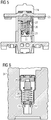
- Fig. 1 shows a known from the prior art contact arrangement with a contact carrier 1, which is a movable Switching piece 2 leads, wherein the movable contact piece 2 is acted upon on one side by a contact spring 3. From the opposite side, that is, from the side of the movable contact piece 2, a spring clip 4 is inserted into the contact carrier 1. To support the contact spring 3, a steel disc 5 is mounted under the contact spring 3 by means of a rotary motion.
- FIG. 2 shows a contact arrangement with a contact carrier 6, which leads a movable contact piece 7, wherein the movable contact piece 7 superimposed on a contact spring 8, which is inserted from below into the contact carrier 6.
- a spring clip 9 is pushed from below into the contact carrier 6.
- the movable contact piece 7 is placed from above between the two legs of the spring clip 9.
- the contact spring 8 is compressed, so that a bolt 10 can be pushed to secure the contact piece from the side through the holes at the leg ends of the spring clip 9.
- the EP 0 798 752 A2 discloses a contact arrangement for an electromechanical switching device with a fixedly positioned contact piece and a movable contact piece arranged opposite thereto, which is mounted in a contact carrier above a contact spring, wherein the movable contact piece and the contact spring are captively covered by an integrally formed, elastic element, wherein the elastic element is U-shaped with two opposite legs which are interconnected by a connecting portion, wherein the opposite leg ends of the elastic member have a smaller distance from each other than the leg portions which adjoin in the connecting portion of the U-shaped elastic member , wherein at the leg ends of the elastic member opposite bearing lips for the fixed positioning of the contact spring are arranged within the elastic member and wherein the Positioning lips are aligned inwardly in the direction of the contact spring, such that a part of the turns of the first end of the contact spring is attached to the bearing lips.
- the object of the present invention is to provide a contact arrangement for an electromechanical switching device, which allows easy installation.
- this object is achieved by a contact arrangement for an electromechanical switching device with a fixedly positioned switching piece and a movable contact piece arranged opposite thereto, which is mounted in a contact carrier above a contact spring.
- the invention is characterized in that the movable contact piece and the contact spring are captively covered by an integrally formed elastic element.
- the elastic element according to the invention is preferably formed as a symmetrically formed spring clip, which can be produced from a steel strip.
- the elastic member is preferably U-shaped with two opposing legs joined together by a connecting portion, the leg portions immediately adjacent and opposite the connecting portion being spaced further apart from each other than the leg portions adjacent to Leg ends are positioned. In the region of the leg ends opposite bearing lips are arranged, which allow a fixed positioning of the contact spring within the elastic member.
- the bearing lips on the leg ends of the elastic element are preferably aligned inwardly in the direction of the contact spring, such that a part of the turns of a first end of the contact spring can be plugged onto the bearing lips.
- the connecting region of the elastic element preferably has an inside elevation on which the movable contact is mounted.
- the spring clip Due to the special shape of the spring bearing point at the lower end of the spring clip, the spring clip can be inserted in a straight line from above into the contact carrier. At the same time a secure and stable storage of the contact spring is achieved by this shaping. Additional parts are not required for the spring bearing or for the attachment of the contact piece.
- the elastic element is a symmetrically formed spring clip. This design enables a secure and stable mounting of the contact spring.
- the elastic element is made of a steel strip.
- the production of the elastic element of a steel strip according to the invention enables a cost-effective production.
- the elastic element is U-shaped with two opposite legs, which are interconnected by a connecting portion.
- the symmetrical design of the elastic element allows for easy assembly, since no preferred alignment of the elastic element is required for the positioning of the elastic element on the contact slide.
- the opposite leg ends of the elastic element have a smaller distance from one another than the leg regions which adjoin the connecting region of the U-shaped elastic element. The mutually supplied legs of the U-shaped elastic element take over this configuration, a guide function for the contact spring mounted between them.
- opposite bearing lips for the fixed positioning of the contact spring are arranged inside the elastic element at the leg ends of the elastic element.
- the storage lips are preferably aligned inward towards the contact spring so that a portion of the turns of the contact spring are attachable to these bearing lips.
- the bearing lips are aligned inwardly in the direction of the contact spring such that a portion of the turns of the contact spring can be plugged onto the bearing lips. The bearing lips thus ensure a secure positioning of the contact spring.
- connection region of the elastic element has an inside elevation on which the moveable contact is mounted.
- the contact arrangement according to the invention is used in an electromechanical switching device.
- this switching device is a contactor.
- the contact arrangement according to the invention for electromechanical switching devices is characterized by the use of an elastic element in the form of a spring clip, which is formed in one piece and captive, so that the spring bearing or the attachment of the contact piece can be implemented without additional parts.
- Fig. 1 shows a known from the prior art contact arrangement with a contact carrier 1, which leads a movable contact piece 2, wherein the movable contact piece 2 is acted upon on one side by a contact spring 3. From the opposite side, that is from the side of the movable contact piece 2, a spring clip 4 is inserted into the contact carrier 1. To support the contact spring. 3 is mounted under the contact spring 3 by means of a rotary motion, a steel plate 5.
- FIG. 2 a further embodiment of a known from the prior art contact arrangement is shown.
- Fig. 2 shows a contact arrangement with a contact carrier 6, which leads a movable contact piece 7, wherein the movable contact piece 7 superimposed on a contact spring 8, which is inserted from below into the contact carrier 6.
- a spring clip 9 is pushed from below into the contact carrier 6.
- the movable contact piece 7 is placed from above between the two legs of the spring clip 9.
- the contact spring 8 is compressed, so that a bolt 10 can be pushed to secure the contact piece 7 from the side through the holes at the leg ends of the spring clip 9.
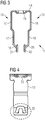
- the elastic element 11 of a contact arrangement according to the invention is shown.
- the elastic element 11 according to the invention is preferably formed as a symmetrically formed spring clip, which is preferably produced from a steel strip.
- the elastic element 11 is preferably U-shaped with two opposite legs 12, 13, which are interconnected by a connecting portion 14, wherein the leg portions 15, 16, which directly adjoin the connecting portion 14, are further spaced from each other than the Leg portions 17, 18 which are positioned in the vicinity of the leg ends 19, 20.
- connection area 14 of the elastic element 11 preferably has an inside elevation 23, on which the movable contact is mounted.
- Fig. 4 shows the leg 13 of the elastic member 11 with the bearing lip 22. From this illustration, it is apparent that the bearing lip 22 is formed inwardly and upward in the direction of the elevation 23.
- Fig. 5 is a contact arrangement according to the invention for an electromechanical switching device shown with a contact carrier 24, in which a movable contact piece 25 is guided.
- the movable contact piece 25 is acted upon from below by a contact spring 26.
- the contact spring 26 is comprised of the elastic element 11 in the form of a spring clip.
- the bearing lip 21 of the elastic element 11 is aligned inwardly in the direction of the contact spring 26, such that a portion of the turns of the first end of the contact spring 26 can be plugged onto the bearing lip 21.
- an elevation (27) is formed on a transverse web in the contact carrier (24), on which part of the turns of the second end of the contact spring (26) can be plugged.
- the contact spring (26) is thus firmly positioned between the elevation (27) on the transverse web of the contact carrier (26) and the bearing lips (21, 22).
- Fig. 6 shows the contact arrangement according to the invention with elastic element 11. Off Fig. 6 shows how the elastic element 11 includes the contact spring 26.
- the contact arrangement according to the invention for electromechanical switching devices is characterized by the use of an elastic element in the form of a spring clip, which is formed in one piece and captive, so that the spring bearing or the attachment of the contact piece can be implemented without additional parts.
- an elastic element in the form of a spring clip, which is formed in one piece and captive, so that the spring bearing or the attachment of the contact piece can be implemented without additional parts.
Landscapes
- Physics & Mathematics (AREA)
- Electromagnetism (AREA)
- Contacts (AREA)
- Manufacture Of Switches (AREA)
- Rotary Switch, Piano Key Switch, And Lever Switch (AREA)
Description
- Die Erfindung betrifft eine Kontaktanordnung für ein elektromechanisches Schaltgerät mit einem fest positionierten Schaltstück und einem dazu gegenüberliegend angeordneten beweglichen Schaltstück, welches in einem Kontaktträger oberhalb von einer Kontaktfeder gelagert ist.
- Schaltgeräte, wie zum Beispiel Leistungsschalter oder Schütze, besitzen bewegliche Schaltstücke, die beim Betätigen Stromkreise öffnen und schließen. Diese beweglichen Schaltstücke werden in beweglichen Kontaktschiebern gehalten und geführt, um einen gerichteten Bewegungsablauf zu den jeweiligen Endpositionen, in welchen das Schaltgerät ein- oder ausgeschaltet ist, zu erhalten. Es ist technisch notwendig, dass bei einem eingeschalteten Schaltgerät der Kontaktschieber zum beweglichen Schaltstück ein Spiel aufweist. Dieses Spiel ist notwendig, um Toleranzen der einzelnen Bauteile und den Abbrand von Kontaktmaterial ausgleichen zu können. Innerhalb dieses Spiels ist der Kontaktschieber frei beweglich.
- Bei elektromechanischen Schaltgeräten werden die beweglichen Schaltstücke durch Kontaktfedern mit einer festgelegten Kontaktkraft auf die Festschaltstücke gepresst. Diese Kontaktfeder kann direkt auf dem beweglichen Schaltstück angebracht sein und sich auf der anderen Seite am Kontaktträger abstützen oder man überträgt die Federkraft über einen Federbügel, der meist aus einem Stahlband hergestellt wird, auf das Schaltstück. Der Federbügel bietet Vorteile durch höhere Festigkeit bei Kurzschlüssen, wodurch eine geringere Bauhöhe für das Gesamtgerät benötigt wird. Allerdings sind für das Festsetzen der Kontaktfeder in der Regel zusätzliche Teile und Montageaufwendungen erforderlich.
-
Fig. 1 zeigt eine aus dem Stand der Technik bekannte Kontaktanordnung mit einem Kontaktträger 1, welcher ein bewegliches Schaltstück 2 führt, wobei das bewegliche Schaltstück 2 auf der einen Seite von einer Kontaktfeder 3 beaufschlagt ist. Von der gegenüberliegenden Seite, das heißt, von der Seite des beweglichen Schaltstücks 2, ist ein Federbügel 4 in den Kontaktträger 1 eingeführt. Zur Abstützung der Kontaktfeder 3 ist unter der Kontaktfeder 3 mittels einer Drehbewegung eine Stahlscheibe 5 montiert. - Eine weitere, aus dem Stand der Technik bekannte Kontaktanordnung ist in
Fig. 2 dargestellt.Fig. 2 zeigt eine Kontaktanordnung mit einem Kontaktträger 6, welcher ein bewegliches Schaltstück 7 führt, wobei das bewegliche Schaltstück 7 auf einer Kontaktfeder 8 lagert, die von unten in den Kontaktträger 6 eingeführt wird. Ebenso wird ein Federbügel 9 von unten in den Kontaktträger 6 geschoben. Das bewegliche Schaltstück 7 wird von oben zwischen die beiden Schenkel des Federbügels 9 gelegt. Durch Drücken auf das Ende des Federbügels 9 wird die Kontaktfeder 8 zusammengedrückt, so dass ein Bolzen 10 zur Sicherung des Schaltstücks von der Seite durch die Löcher an den Schenkelenden des Federbügels 9 geschoben werden kann. - Die
EP 0 798 752 A2 offenbart eine Kontaktanordnung für ein elektromechanisches Schaltgerät mit einem fest positionierten Schaltstück und einem dazu gegenüberliegend angeordneten beweglichen Schaltstück, welches in einem Kontaktträger oberhalb von einer Kontaktfeder gelagert ist, wobei das bewegliche Schaltstück und die Kontaktfeder von einem einstückig ausgebildeten, elastischen Element verliersicher umfasst sind, wobei das elastische Element U-förmig ausgebildet ist mit zwei sich gegenüberliegenden Schenkeln, die durch einen Verbindungsbereich miteinander verbunden sind, wobei die sich gegenüberliegenden Schenkelenden des elastischen Elements einen kleineren Abstand zueinander aufweisen als die Schenkelbereiche, die sich im Verbindungsbereich des U-förmigen elastischen Elements anschließen, wobei an den Schenkelenden des elastischen Elements sich gegenüberliegende Lagerungslippen für die feste Positionierung der Kontaktfeder innerhalb des elastischen Elements angeordnet sind und wobei die Lagerungslippen nach innen in Richtung der Kontaktfeder ausgerichtet sind, derart, dass ein Teil der Windungen des ersten Endes der Kontaktfeder an den Lagerungslippen aufgesteckt ist. - Aus der
WO 2011/095219 A1 , derEP 2 290 672 A1 und derDE 10 2012 219961 A1 gehen weitere Ausführungsbeispiele für einen Kontaktträger beziehungsweise für Führungselemente für ein bewegliches Schaltstück hervor. - Die aus dem Stand der Technik bekannten Kontaktanordnungen mit Federbügel weisen den Nachteil auf, dass für das Festsetzen der Kontaktfeder in der Regel zusätzliche Teile benötigt werden, wodurch der Montageaufwand erhöht wird.
- Demgemäß besteht die Aufgabe der vorliegenden Erfindung darin, eine Kontaktanordnung für ein elektromechanisches Schaltgerät zu schaffen, die eine einfache Montage ermöglicht.
- Diese Aufgabe wird erfindungsgemäß durch eine Kontaktanordnung mit den Merkmalen des Patentanspruchs 1 gelöst. Vorteilhafte Aus- und Weiterbildungen, welche einzeln oder in Kombination miteinander eingesetzt werden können, sind der Gegenstand der abhängigen Ansprüche.
- Erfindungsgemäß wird diese Aufgabe durch eine Kontaktanordnung für ein elektromechanisches Schaltgerät mit einem fest positionierten Schaltstück und einem dazu gegenüberliegend angeordneten beweglichen Schaltstück gelöst, welches in einem Kontaktträger oberhalb von einer Kontaktfeder gelagert ist. Die Erfindung zeichnet sich dabei dadurch aus, dass das bewegliche Schaltstück und die Kontaktfeder von einem einstückig ausgebildeten elastischen Element verliersicher umfasst sind.
- Das erfindungsgemäße elastische Element ist vorzugsweise als symmetrisch ausgebildeter Federbügel ausgeformt, welcher aus einem Stahlband herstellbar ist. Das elastische Element ist vorzugsweise U-förmig ausgebildet mit zwei sich gegenüberliegenden Schenkeln, die durch einen Verbindungsbereich miteinander verbunden sind, wobei die Schenkelbereiche, die sich direkt am Verbindungsbereich anschließen und gegenüberliegen, weiter voneinander beabstandet sind, als die Schenkelbereiche, die in der Nähe der Schenkelenden positioniert sind. Im Bereich der Schenkelenden sind sich gegenüberliegende Lagerungslippen angeordnet, die eine feste Positionierung der Kontaktfeder innerhalb des elastischen Elements ermöglichen. Die Lagerungslippen an den Schenkelenden des elastischen Elements sind vorzugsweise nach innen in Richtung der Kontaktfeder ausgerichtet, derart, dass ein Teil der Windungen eines ersten Endes der Kontaktfeder auf den Lagerungslippen aufsteckbar sind. Der Verbindungsbereich des elastischen Elements weist vorzugsweise eine innenseitige Erhebung auf, an der der bewegliche Kontakt gelagert ist.
- Durch die besondere Formgebung der Federlagerstelle am unteren Ende des Federbügels kann der Federbügel gradlinig von oben in den Kontaktträger gesteckt werden. Gleichzeitig wird durch diese Formgebung eine sichere und stabile Lagerung der Kontaktfeder erreicht. Zusätzliche Teile sind für die Federlagerung beziehungsweise für die Befestigung des Schaltstücks nicht erforderlich.
- In einer besonders vorteilhaften Ausgestaltung der Erfindung kann es vorgesehen sein, dass das elastische Element ein symmetrisch ausgebildeter Federbügel ist. Durch diese Formgebung wird eine sichere und stabile Lagerung der Kontaktfeder ermöglicht.
- In einer Fortführung dieses erfindungsgemäßen Konzepts kann es vorgesehen sein, dass das elastische Element aus einem Stahlband hergestellt ist. Die Herstellung des erfindungsgemäßen elastischen Elements aus einem Stahlband ermöglicht eine kostengünstige Herstellung. Gemäß der Erfindung ist das elastische Element U-förmig ausgebildet mit zwei sich gegenüberliegenden Schenkeln, die durch einen Verbindungsbereich miteinander verbunden sind. Die symmetrische Ausbildung des elastischen Elements ermöglicht eine einfache Montage, da für die Positionierung des elastischen Elements am Kontaktschieber keine bevorzugte Ausrichtung des elastischen Elements benötigt wird. Erfindungsgemäß weisen die sich gegenüberliegenden Schenkelenden des elastischen Elements einen kleineren Abstand zueinander auf als die Schenkelbereiche, die sich am Verbindungsbereich des U-förmigen elastischen Elements anschließen. Die aufeinander zugeführten Schenkel des U-förmigen elastischen Elements übernehmen durch diese Ausgestaltung eine Führungsfunktion für die zwischen ihnen gelagerte Kontaktfeder. Gemäß der Erfindung sind an den Schenkelenden des elastischen Elements sich gegenüberliegende Lagerungslippen für die feste Positionierung der Kontaktfeder innerhalb des elastischen Elements angeordnet. Die Lagerungslippen sind dabei vorzugsweise nach innen in Richtung der Kontaktfeder ausgerichtet, so dass ein Teil der Windungen der Kontaktfeder auf diese Lagerungslippen aufsteckbar sind. Erfindungsgemäß sind die Lagerungslippen nach innen in Richtung der Kontaktfeder derart ausgerichtet, dass ein Teil der Windungen der Kontaktfeder auf den Lagerungslippen aufsteckbar sind. Die Lagerungslippen gewährleisten so eine sichere Positionierung der Kontaktfeder.
- In einer weiteren speziellen Fortführung des erfindungsgemäßen Konzepts kann es vorgesehen sein, dass der Verbindungsbereich des elastischen Elements eine innenseitige Erhebung aufweist, an der der bewegliche Kontakt gelagert ist. Gemäß der Erfindung weist ein Quersteg im Kontaktträger eine Erhöhung auf, auf welcher ein Teil der Windungen des zweiten Endes der Kontaktfeder aufsteckbar ist. Die Kontaktfeder ist somit zwischen der Erhöhung am Quersteg des Kontaktträgers und den Lagerungslippen fest positioniert.
- Erfindungsgemäß kann es außerdem vorgesehen sein, dass die erfindungsgemäße Kontaktanordnung in einem elektromechanischen Schaltgerät Anwendung findet. Vorzugsweise handelt es sich bei diesem Schaltgerät um einen Schütz.
- Die erfindungsgemäße Kontaktanordnung für elektromechanische Schaltgeräte zeichnet sich durch Verwendung eines elastischen Elements in Form eines Federbügels aus, der einstückig und verliersicher ausgebildet ist, so dass die Federlagerung bzw. die Befestigung des Schaltstücks ohne zusätzliche Teile umgesetzt werden kann. Diese Merkmale ergeben sich durch eine besondere Kröpfung und Anphasung am unteren Teil des Federbügels. In Verbindung mit einer entsprechenden Formgebung am Kontaktträger kann der Federbügel ohne Hilfsmittel und Vorrichtungen gradlinig in den Kontaktträger geschoben werden. Die Innenkontur wird hierbei so geformt, dass die Kontaktdruckfeder sicher gegen Verrutschen gelagert wird. Es ergibt sich so eine sehr gute Lagerung der Kontaktfeder bei geringem Montage- und Teileaufwand und geringer Gerätebauhöhe. Weitere Vorteile und Ausführungen der Erfindung werden nachfolgend anhand eines Ausführungsbeispiels sowie anhand der Zeichnung erläutert.
- Dabei zeigen schematisch:
-
Fig. 1 in einer Schnittdarstellung ein erstes Ausführungsbeispiel für eine aus dem Stand der Technik bekannte Kontaktanordnung für elektromechanische Schaltgeräte; -
Fig. 2 in einer Schnittdarstellung ein zweites Ausführungsbeispiel für eine aus dem Stand der Technik bekannte Kontaktanordnung für ein elektromechanisches Schaltgerät; -
Fig. 3 in einer Draufsicht ein erfindungsgemäßes elastisches Element für eine Kontaktanordnung; -
Fig. 4 in einer Schnittdarstellung das erfindungsgemäße elastische Element nachFig. 3 ; -
Fig. 5 in einer Schnittdarstellung eine erfindungsgemäße Kontaktanordnung mit elastischem Element; -
Fig. 6 in einer Schnittdarstellung die Kontaktanordnung nachFig. 5 . -
Fig. 1 zeigt eine aus dem Stand der Technik bekannte Kontaktanordnung mit einem Kontaktträger 1, welcher ein bewegliches Schaltstück 2 führt, wobei das bewegliche Schaltstück 2 auf der einen Seite von einer Kontaktfeder 3 beaufschlagt ist. Von der gegenüberliegenden Seite, das heißt von der Seite des beweglichen Schaltstücks 2, ist ein Federbügel 4 in den Kontaktträger 1 eingeführt. Zur Abstützung der Kontaktfeder 3 ist unter der Kontaktfeder 3 mittels einer Drehbewegung eine Stahlscheibe 5 montiert. - In
Fig. 2 ist ein weiteres Ausführungsbeispiel für eine aus dem Stand der Technik bekannte Kontaktanordnung dargestellt.Fig. 2 zeigt eine Kontaktanordnung mit einem Kontaktträger 6, welcher ein bewegliches Schaltstück 7 führt, wobei das bewegliche Schaltstück 7 auf einer Kontaktfeder 8 lagert, die von unten in den Kontaktträger 6 eingeführt wird. Ebenso wird ein Federbügel 9 von unten in den Kontaktträger 6 geschoben. Das bewegliche Schaltstück 7 wird von oben zwischen die beiden Schenkel des Federbügels 9 gelegt. Durch Drücken auf das Ende des Federbügels 9 wird die Kontaktfeder 8 zusammengedrückt, so dass ein Bolzen 10 zur Sicherung des Schaltstücks 7 von der Seite durch die Löcher an den Schenkelenden des Federbügels 9 geschoben werden kann. - In
Fig. 3 ist ein elastisches Element 11 einer erfindungsgemäßen Kontaktanordnung dargestellt. Das erfindungsgemäße elastische Element 11 ist vorzugsweise als symmetrisch ausgebildeter Federbügel ausgeformt, welcher vorzugsweise aus einem Stahlband herstellbar ist. Das elastische Element 11 ist vorzugsweise U-förmig ausgebildet mit zwei sich gegenüberliegenden Schenkel 12, 13, die durch einen Verbindungsbereich 14 miteinander verbunden sind, wobei die Schenkelbereiche 15, 16, die sich direkt am Verbindungsbereich 14 anschließen, weiter voneinander beabstandet sind, als die Schenkelbereiche 17, 18, die in der Nähe der Schenkelenden 19, 20 positioniert sind. - Im Bereich der Schenkelenden 19, 20 sind sich gegenüberliegende Lagerungslippen 21, 22 angeordnete, in die eine feste Positionierung einer Kontaktfeder innerhalb des elastischen Elements 11 ermöglichen. Die Lagerungslippen 21, 22 an den Schenkelenden 19, 20 des elastischen Elements 11 sind vorzugsweise nach innen ausgerichtet, derart, dass ein Teil der Windungen eines ersten Endes einer Kontaktfeder auf den Lagerungslippen 21, 22 aufsteckbar sind. Der Verbindungsbereich 14 des elastischen Elements 11 weist vorzugsweise eine innenseitige Erhebung 23 auf, an der der bewegliche Kontakt gelagert ist.
Fig. 4 zeigt den Schenkel 13 des elastischen Elements 11 mit der Lagerungslippe 22. Aus dieser Darstellung geht hervor, dass die Lagerungslippe 22 nach innen und oben in Richtung der Erhebung 23 ausgebildet ist. - In
Fig. 5 ist eine erfindungsgemäße Kontaktanordnung für ein elektromechanisches Schaltgerät dargestellt mit einem Kontaktträger 24, in welchem ein bewegliches Schaltstück 25 geführt ist. Das bewegliche Schaltstück 25 wird von unten von einer Kontaktfeder 26 beaufschlagt. Die Kontaktfeder 26 wird vom elastischen Element 11 in Form eines Federbügels umfasst. Dabei ist die Lagerungslippe 21 des elastischen Elements 11 nach innen in Richtung der Kontaktfeder 26 ausgerichtet, derart, dass ein Teil der Windungen des ersten Endes der Kontaktfeder 26 auf der Lagerungslippe 21 aufsteckbar ist. Zudem ist an einem Quersteg im Kontaktträger (24) eine Erhöhung (27) ausgebildet, auf welcher ein Teil der Windungen des zweiten Endes der Kontaktfeder (26) aufsteckbar ist. Die Kontaktfeder (26) ist somit zwischen der Erhöhung (27) am Quersteg des Kontaktträgers (26) und den Lagerungslippen (21, 22) fest positioniert. -
Fig. 6 zeigt die erfindungsgemäße Kontaktanordnung mit elastischem Element 11. AusFig. 6 geht hervor, wie das elastische Element 11 die Kontaktfeder 26 umfasst. - Die erfindungsgemäße Kontaktanordnung für elektromechanische Schaltgeräte zeichnet sich durch Verwendung eines elastischen Elements in Form eines Federbügels aus, der einstückig und verliersicher ausgebildet ist, so dass die Federlagerung bzw. die Befestigung des Schaltstücks ohne zusätzliche Teile umgesetzt werden kann. Diese Merkmale ergeben sich durch eine besondere Kröpfung und Anphasung am unteren Teil des Federbügels. In Verbindung mit einer entsprechenden Formgebung am Kontaktträger kann der Federbügel ohne Hilfsmittel und Vorrichtungen gradlinig in den Kontaktträger geschoben werden. Die Innenkontur wird hierbei so geformt, dass die Kontaktdruckfeder sicher gegen Verrutschen gelagert wird. Es ergibt sich so eine sehr gute Lagerung der Kontaktfeder bei geringem Montage- und Teileaufwand und geringer Gerätebauhöhe.
-
- 1
- Kontaktträger
- 2
- bewegliches Schaltstück
- 3
- Kontaktfeder
- 4
- Federbügel
- 5
- Stahlscheibe
- 6
- Kontaktträger
- 7
- bewegliches Schaltstück
- 8
- Kontaktfeder
- 9
- Federbügel
- 10
- Bolzen
- 11
- elastisches Element
- 12
- Schenkel
- 13
- Schenkel
- 14
- Verbindungsbereich
- 15
- Schenkelbereich
- 16
- Schenkelbereich
- 17
- Schenkelbereich
- 18
- Schenkelbereich
- 19
- Schenkelende
- 20
- Schenkelende
- 21
- Lagerungslippe
- 22
- Lagerungslippe
- 23
- Erhebung
- 24
- Kontaktträger
- 25
- bewegliches Schaltstück
- 26
- Kontaktfeder
- 27
- Erhöhung
Claims (6)
- Kontaktanordnung für ein elektromechanisches Schaltgerät mit einem fest positionierten Schaltstück und einem dazu gegenüberliegend angeordneten beweglichen Schaltstück (25), welches in einem Kontaktträger (24) oberhalb von einer Kontaktfeder (26) gelagert ist, wobei das bewegliche Schaltstück (25) und die Kontaktfeder (26) von einem einstückig ausgebildeten, elastischen Element (11) verliersicher umfaßt sind, wobei das elastische Element (11) U-förmig ausgebildet ist mit zwei sich gegenüberliegenden Schenkeln (12,13), die durch einen Verbindungsbereich (14) miteinander verbunden sind, wobei die sich gegenüberliegenden Schenkelenden (19,20) des elastischen Elements (11) einen kleineren Abstand zueinander aufweisen als die Schenkelbereiche (15,16), die sich im Verbindungsbereich (14) des U-förmigen elastischen Elements (11) anschließen, wobei an den Schenkelenden (19,20) des elastischen Elements (11) sich gegenüberliegende Lagerungslippen (21,22) für die feste Positionierung der Kontaktfeder (26) innerhalb des elastischen Elements (11) angeordnet sind und wobei die Lagerungslippen (21,22) nach innen in Richtung der Kontaktfeder (26) ausgerichtet sind, derart, dass ein Teil der Windungen des ersten Endes der Kontaktfeder (26) auf den Lagerungslippen (21,22) aufgesteckt ist, dadurch gekennzeichnet, dass ein Quersteg im Kontaktträger (24) eine Erhöhung (27) aufweist, auf welcher ein Teil der Windungen des zweiten Endes der Kontaktfeder (26) aufsteckbar ist.
- Kontaktanordnung nach Anspruch 1, dadurch gekennzeichnet, dass das elastische Element (11) ein symmetrisch ausgebildeter Federbügel ist.
- Kontaktanordnung nach Anspruch 1 oder 2, dadurch gekennzeichnet, dass das elastische Element (11) aus einem Stahlband gefertigt ist.
- Kontaktanordnung nach Anspruch 1, dadurch gekennzeichnet, dass der Verbindungsbereich (14) des elastischen Elements (11) eine innenseitige Erhebung (23) aufweist, an der der bewegliche Kontakt gelagert ist.
- Elektromechanisches Schaltgerät mit einer Kontaktanordnung nach einem der Ansprüche 1 bis 4.
- Schaltgerät nach Anspruch 5, dadurch gekennzeichnet, dass das Schaltgerät ein Schütz ist.
Applications Claiming Priority (1)
| Application Number | Priority Date | Filing Date | Title |
|---|---|---|---|
| DE102014219911.5A DE102014219911A1 (de) | 2014-10-01 | 2014-10-01 | Kontaktanordnung für ein elektromechanisches Schaltgerät |
Publications (2)
| Publication Number | Publication Date |
|---|---|
| EP3002767A1 EP3002767A1 (de) | 2016-04-06 |
| EP3002767B1 true EP3002767B1 (de) | 2017-05-31 |
Family
ID=54065793
Family Applications (1)
| Application Number | Title | Priority Date | Filing Date |
|---|---|---|---|
| EP15184233.3A Active EP3002767B1 (de) | 2014-10-01 | 2015-09-08 | Kontaktanordnung für ein elektromechanisches schaltgerät |
Country Status (3)
| Country | Link |
|---|---|
| EP (1) | EP3002767B1 (de) |
| CN (1) | CN105489406B (de) |
| DE (1) | DE102014219911A1 (de) |
Families Citing this family (2)
| Publication number | Priority date | Publication date | Assignee | Title |
|---|---|---|---|---|
| JP6844573B2 (ja) | 2018-03-30 | 2021-03-17 | オムロン株式会社 | リレー |
| DE102023111832A1 (de) * | 2023-05-05 | 2024-11-07 | Te Connectivity Solutions Gmbh | Kontaktbrückenanordnung für ein Relais oder Schütz |
Family Cites Families (6)
| Publication number | Priority date | Publication date | Assignee | Title |
|---|---|---|---|---|
| US5892194A (en) * | 1996-03-26 | 1999-04-06 | Matsushita Electric Works, Ltd. | Sealed contact device with contact gap adjustment capability |
| JP3829963B2 (ja) * | 1998-08-25 | 2006-10-04 | 富士電機機器制御株式会社 | 多極開閉器の可動接触子装置 |
| SE516457C2 (sv) * | 1999-01-28 | 2002-01-15 | Asea Brown Boveri | Brytare i kontaktor |
| EP2290672B1 (de) * | 2009-08-24 | 2015-06-24 | Siemens Aktiengesellschaft | Kontaktanordnung für elektromechanische Hilfsschalter |
| CN102754177B (zh) * | 2010-02-05 | 2015-09-30 | 西门子公司 | 用于电磁开关装置的保持装置 |
| DE102012219961B4 (de) * | 2012-10-31 | 2014-10-02 | Tyco Electronics Amp Gmbh | Schalter |
-
2014
- 2014-10-01 DE DE102014219911.5A patent/DE102014219911A1/de not_active Withdrawn
-
2015
- 2015-09-08 EP EP15184233.3A patent/EP3002767B1/de active Active
- 2015-09-28 CN CN201510629734.0A patent/CN105489406B/zh active Active
Also Published As
| Publication number | Publication date |
|---|---|
| DE102014219911A1 (de) | 2016-04-07 |
| CN105489406A (zh) | 2016-04-13 |
| EP3002767A1 (de) | 2016-04-06 |
| CN105489406B (zh) | 2018-10-16 |
Similar Documents
| Publication | Publication Date | Title |
|---|---|---|
| EP2843676B1 (de) | Schaltvorrichtung | |
| WO2009115385A1 (de) | Wischblatt | |
| EP0218133B1 (de) | Schraubenlose elektrische Klemme | |
| WO2018228877A1 (de) | Tragschienenbefestigung | |
| DE102017117509A1 (de) | Elektrisches Gerät | |
| DE29919903U1 (de) | Zugfederanschluß für große Leiterquerschnitte | |
| EP2463968B1 (de) | Verbindungselement für ein Lichtbandschienensystem bzw. ein Tragschienensystem für stabförmige Leuchtmittel | |
| EP2290672B1 (de) | Kontaktanordnung für elektromechanische Hilfsschalter | |
| EP2139017B1 (de) | Verbindungselement für Installationsgeräte, insbesondere für Niederspannungsschaltgeräte | |
| DE2013779B2 (de) | Elektrischer druckknopfschalter | |
| WO2016079077A1 (de) | Federkraftklemme | |
| DE19726149C2 (de) | Schalteranordnung | |
| EP2916686B1 (de) | Gleitführungselement und tischplattenbefestigungssystem zur verschiebbaren befestigung einer tischplatte | |
| EP3021439A2 (de) | Elektronisches installationsgerät | |
| DE29821558U1 (de) | Schutzleiterklemme | |
| EP3002767A1 (de) | Kontaktanordnung für ein elektromechanisches schaltgerät | |
| DE102004018904B4 (de) | Schraubenloser Sammelschienenanschluss für elektrische Klemmen | |
| EP3276761B1 (de) | Befestigungsvorrichtung für ein in einem gehäuse befindliches elektrisches bauteil | |
| DE2611446A1 (de) | Elektrische anschlussvorrichtung, insbesondere fuer leiterplatten | |
| DE202010010424U1 (de) | Wanddurchführungsklemme für elektrische Leiter | |
| WO2014191291A1 (de) | Lenkradeinheit | |
| WO1998044770A1 (de) | Vorrichtung zum befestigen eines schirmdeckels | |
| DE102014207496B4 (de) | Verriegelungsvorrichtung für eine modulare Reihenbaugruppe, Reihenbaugruppe und Sammelschienenverbund | |
| DE102006041803B4 (de) | Vorrichtung zur Befestigung eines Gerätes an einer Tragschiene | |
| DE9310630U1 (de) | An einer Montagefläche befestigtes elektrisches Gerät |
Legal Events
| Date | Code | Title | Description |
|---|---|---|---|
| PUAI | Public reference made under article 153(3) epc to a published international application that has entered the european phase |
Free format text: ORIGINAL CODE: 0009012 |
|
| AK | Designated contracting states |
Kind code of ref document: A1 Designated state(s): AL AT BE BG CH CY CZ DE DK EE ES FI FR GB GR HR HU IE IS IT LI LT LU LV MC MK MT NL NO PL PT RO RS SE SI SK SM TR |
|
| AX | Request for extension of the european patent |
Extension state: BA ME |
|
| 17P | Request for examination filed |
Effective date: 20160720 |
|
| RBV | Designated contracting states (corrected) |
Designated state(s): AL AT BE BG CH CY CZ DE DK EE ES FI FR GB GR HR HU IE IS IT LI LT LU LV MC MK MT NL NO PL PT RO RS SE SI SK SM TR |
|
| GRAP | Despatch of communication of intention to grant a patent |
Free format text: ORIGINAL CODE: EPIDOSNIGR1 |
|
| INTG | Intention to grant announced |
Effective date: 20170104 |
|
| GRAS | Grant fee paid |
Free format text: ORIGINAL CODE: EPIDOSNIGR3 |
|
| GRAA | (expected) grant |
Free format text: ORIGINAL CODE: 0009210 |
|
| AK | Designated contracting states |
Kind code of ref document: B1 Designated state(s): AL AT BE BG CH CY CZ DE DK EE ES FI FR GB GR HR HU IE IS IT LI LT LU LV MC MK MT NL NO PL PT RO RS SE SI SK SM TR |
|
| REG | Reference to a national code |
Ref country code: CH Ref legal event code: EP Ref country code: GB Ref legal event code: FG4D Free format text: NOT ENGLISH |
|
| REG | Reference to a national code |
Ref country code: AT Ref legal event code: REF Ref document number: 898132 Country of ref document: AT Kind code of ref document: T Effective date: 20170615 |
|
| REG | Reference to a national code |
Ref country code: IE Ref legal event code: FG4D Free format text: LANGUAGE OF EP DOCUMENT: GERMAN |
|
| REG | Reference to a national code |
Ref country code: DE Ref legal event code: R096 Ref document number: 502015001142 Country of ref document: DE |
|
| RAP2 | Party data changed (patent owner data changed or rights of a patent transferred) |
Owner name: SIEMENS AKTIENGESELLSCHAFT |
|
| REG | Reference to a national code |
Ref country code: CH Ref legal event code: NV Representative=s name: SIEMENS SCHWEIZ AG, CH Ref country code: CH Ref legal event code: PCOW Free format text: NEW ADDRESS: WERNER-VON-SIEMENS-STRASSE 1, 80333 MUENCHEN (DE) |
|
| REG | Reference to a national code |
Ref country code: NL Ref legal event code: MP Effective date: 20170531 |
|
| REG | Reference to a national code |
Ref country code: LT Ref legal event code: MG4D |
|
| PG25 | Lapsed in a contracting state [announced via postgrant information from national office to epo] |
Ref country code: LT Free format text: LAPSE BECAUSE OF FAILURE TO SUBMIT A TRANSLATION OF THE DESCRIPTION OR TO PAY THE FEE WITHIN THE PRESCRIBED TIME-LIMIT Effective date: 20170531 Ref country code: HR Free format text: LAPSE BECAUSE OF FAILURE TO SUBMIT A TRANSLATION OF THE DESCRIPTION OR TO PAY THE FEE WITHIN THE PRESCRIBED TIME-LIMIT Effective date: 20170531 Ref country code: NO Free format text: LAPSE BECAUSE OF FAILURE TO SUBMIT A TRANSLATION OF THE DESCRIPTION OR TO PAY THE FEE WITHIN THE PRESCRIBED TIME-LIMIT Effective date: 20170831 Ref country code: ES Free format text: LAPSE BECAUSE OF FAILURE TO SUBMIT A TRANSLATION OF THE DESCRIPTION OR TO PAY THE FEE WITHIN THE PRESCRIBED TIME-LIMIT Effective date: 20170531 Ref country code: FI Free format text: LAPSE BECAUSE OF FAILURE TO SUBMIT A TRANSLATION OF THE DESCRIPTION OR TO PAY THE FEE WITHIN THE PRESCRIBED TIME-LIMIT Effective date: 20170531 Ref country code: GR Free format text: LAPSE BECAUSE OF FAILURE TO SUBMIT A TRANSLATION OF THE DESCRIPTION OR TO PAY THE FEE WITHIN THE PRESCRIBED TIME-LIMIT Effective date: 20170901 |
|
| PG25 | Lapsed in a contracting state [announced via postgrant information from national office to epo] |
Ref country code: RS Free format text: LAPSE BECAUSE OF FAILURE TO SUBMIT A TRANSLATION OF THE DESCRIPTION OR TO PAY THE FEE WITHIN THE PRESCRIBED TIME-LIMIT Effective date: 20170531 Ref country code: NL Free format text: LAPSE BECAUSE OF FAILURE TO SUBMIT A TRANSLATION OF THE DESCRIPTION OR TO PAY THE FEE WITHIN THE PRESCRIBED TIME-LIMIT Effective date: 20170531 Ref country code: BG Free format text: LAPSE BECAUSE OF FAILURE TO SUBMIT A TRANSLATION OF THE DESCRIPTION OR TO PAY THE FEE WITHIN THE PRESCRIBED TIME-LIMIT Effective date: 20170831 Ref country code: IS Free format text: LAPSE BECAUSE OF FAILURE TO SUBMIT A TRANSLATION OF THE DESCRIPTION OR TO PAY THE FEE WITHIN THE PRESCRIBED TIME-LIMIT Effective date: 20170930 Ref country code: SE Free format text: LAPSE BECAUSE OF FAILURE TO SUBMIT A TRANSLATION OF THE DESCRIPTION OR TO PAY THE FEE WITHIN THE PRESCRIBED TIME-LIMIT Effective date: 20170531 Ref country code: LV Free format text: LAPSE BECAUSE OF FAILURE TO SUBMIT A TRANSLATION OF THE DESCRIPTION OR TO PAY THE FEE WITHIN THE PRESCRIBED TIME-LIMIT Effective date: 20170531 |
|
| PG25 | Lapsed in a contracting state [announced via postgrant information from national office to epo] |
Ref country code: RO Free format text: LAPSE BECAUSE OF FAILURE TO SUBMIT A TRANSLATION OF THE DESCRIPTION OR TO PAY THE FEE WITHIN THE PRESCRIBED TIME-LIMIT Effective date: 20170531 Ref country code: SK Free format text: LAPSE BECAUSE OF FAILURE TO SUBMIT A TRANSLATION OF THE DESCRIPTION OR TO PAY THE FEE WITHIN THE PRESCRIBED TIME-LIMIT Effective date: 20170531 Ref country code: DK Free format text: LAPSE BECAUSE OF FAILURE TO SUBMIT A TRANSLATION OF THE DESCRIPTION OR TO PAY THE FEE WITHIN THE PRESCRIBED TIME-LIMIT Effective date: 20170531 Ref country code: EE Free format text: LAPSE BECAUSE OF FAILURE TO SUBMIT A TRANSLATION OF THE DESCRIPTION OR TO PAY THE FEE WITHIN THE PRESCRIBED TIME-LIMIT Effective date: 20170531 Ref country code: CZ Free format text: LAPSE BECAUSE OF FAILURE TO SUBMIT A TRANSLATION OF THE DESCRIPTION OR TO PAY THE FEE WITHIN THE PRESCRIBED TIME-LIMIT Effective date: 20170531 |
|
| PG25 | Lapsed in a contracting state [announced via postgrant information from national office to epo] |
Ref country code: SM Free format text: LAPSE BECAUSE OF FAILURE TO SUBMIT A TRANSLATION OF THE DESCRIPTION OR TO PAY THE FEE WITHIN THE PRESCRIBED TIME-LIMIT Effective date: 20170531 Ref country code: PL Free format text: LAPSE BECAUSE OF FAILURE TO SUBMIT A TRANSLATION OF THE DESCRIPTION OR TO PAY THE FEE WITHIN THE PRESCRIBED TIME-LIMIT Effective date: 20170531 Ref country code: IT Free format text: LAPSE BECAUSE OF FAILURE TO SUBMIT A TRANSLATION OF THE DESCRIPTION OR TO PAY THE FEE WITHIN THE PRESCRIBED TIME-LIMIT Effective date: 20170531 |
|
| REG | Reference to a national code |
Ref country code: DE Ref legal event code: R097 Ref document number: 502015001142 Country of ref document: DE |
|
| PLBE | No opposition filed within time limit |
Free format text: ORIGINAL CODE: 0009261 |
|
| STAA | Information on the status of an ep patent application or granted ep patent |
Free format text: STATUS: NO OPPOSITION FILED WITHIN TIME LIMIT |
|
| 26N | No opposition filed |
Effective date: 20180301 |
|
| PG25 | Lapsed in a contracting state [announced via postgrant information from national office to epo] |
Ref country code: MC Free format text: LAPSE BECAUSE OF FAILURE TO SUBMIT A TRANSLATION OF THE DESCRIPTION OR TO PAY THE FEE WITHIN THE PRESCRIBED TIME-LIMIT Effective date: 20170531 Ref country code: SI Free format text: LAPSE BECAUSE OF FAILURE TO SUBMIT A TRANSLATION OF THE DESCRIPTION OR TO PAY THE FEE WITHIN THE PRESCRIBED TIME-LIMIT Effective date: 20170531 |
|
| REG | Reference to a national code |
Ref country code: IE Ref legal event code: MM4A |
|
| REG | Reference to a national code |
Ref country code: BE Ref legal event code: MM Effective date: 20170930 |
|
| PG25 | Lapsed in a contracting state [announced via postgrant information from national office to epo] |
Ref country code: LU Free format text: LAPSE BECAUSE OF NON-PAYMENT OF DUE FEES Effective date: 20170908 |
|
| REG | Reference to a national code |
Ref country code: FR Ref legal event code: ST Effective date: 20180531 |
|
| PG25 | Lapsed in a contracting state [announced via postgrant information from national office to epo] |
Ref country code: IE Free format text: LAPSE BECAUSE OF NON-PAYMENT OF DUE FEES Effective date: 20170908 |
|
| PG25 | Lapsed in a contracting state [announced via postgrant information from national office to epo] |
Ref country code: BE Free format text: LAPSE BECAUSE OF NON-PAYMENT OF DUE FEES Effective date: 20170930 Ref country code: FR Free format text: LAPSE BECAUSE OF NON-PAYMENT OF DUE FEES Effective date: 20171002 |
|
| PG25 | Lapsed in a contracting state [announced via postgrant information from national office to epo] |
Ref country code: MT Free format text: LAPSE BECAUSE OF FAILURE TO SUBMIT A TRANSLATION OF THE DESCRIPTION OR TO PAY THE FEE WITHIN THE PRESCRIBED TIME-LIMIT Effective date: 20170531 |
|
| REG | Reference to a national code |
Ref country code: CH Ref legal event code: PL |
|
| PG25 | Lapsed in a contracting state [announced via postgrant information from national office to epo] |
Ref country code: HU Free format text: LAPSE BECAUSE OF FAILURE TO SUBMIT A TRANSLATION OF THE DESCRIPTION OR TO PAY THE FEE WITHIN THE PRESCRIBED TIME-LIMIT; INVALID AB INITIO Effective date: 20150908 |
|
| PG25 | Lapsed in a contracting state [announced via postgrant information from national office to epo] |
Ref country code: LI Free format text: LAPSE BECAUSE OF NON-PAYMENT OF DUE FEES Effective date: 20180930 Ref country code: CH Free format text: LAPSE BECAUSE OF NON-PAYMENT OF DUE FEES Effective date: 20180930 |
|
| PG25 | Lapsed in a contracting state [announced via postgrant information from national office to epo] |
Ref country code: CY Free format text: LAPSE BECAUSE OF FAILURE TO SUBMIT A TRANSLATION OF THE DESCRIPTION OR TO PAY THE FEE WITHIN THE PRESCRIBED TIME-LIMIT Effective date: 20170531 |
|
| PG25 | Lapsed in a contracting state [announced via postgrant information from national office to epo] |
Ref country code: MK Free format text: LAPSE BECAUSE OF FAILURE TO SUBMIT A TRANSLATION OF THE DESCRIPTION OR TO PAY THE FEE WITHIN THE PRESCRIBED TIME-LIMIT Effective date: 20170531 |
|
| PG25 | Lapsed in a contracting state [announced via postgrant information from national office to epo] |
Ref country code: TR Free format text: LAPSE BECAUSE OF FAILURE TO SUBMIT A TRANSLATION OF THE DESCRIPTION OR TO PAY THE FEE WITHIN THE PRESCRIBED TIME-LIMIT Effective date: 20170531 |
|
| PG25 | Lapsed in a contracting state [announced via postgrant information from national office to epo] |
Ref country code: PT Free format text: LAPSE BECAUSE OF FAILURE TO SUBMIT A TRANSLATION OF THE DESCRIPTION OR TO PAY THE FEE WITHIN THE PRESCRIBED TIME-LIMIT Effective date: 20170531 |
|
| PG25 | Lapsed in a contracting state [announced via postgrant information from national office to epo] |
Ref country code: AL Free format text: LAPSE BECAUSE OF FAILURE TO SUBMIT A TRANSLATION OF THE DESCRIPTION OR TO PAY THE FEE WITHIN THE PRESCRIBED TIME-LIMIT Effective date: 20170531 |
|
| GBPC | Gb: european patent ceased through non-payment of renewal fee |
Effective date: 20190908 |
|
| PG25 | Lapsed in a contracting state [announced via postgrant information from national office to epo] |
Ref country code: GB Free format text: LAPSE BECAUSE OF NON-PAYMENT OF DUE FEES Effective date: 20190908 |
|
| REG | Reference to a national code |
Ref country code: AT Ref legal event code: MM01 Ref document number: 898132 Country of ref document: AT Kind code of ref document: T Effective date: 20200908 |
|
| PG25 | Lapsed in a contracting state [announced via postgrant information from national office to epo] |
Ref country code: AT Free format text: LAPSE BECAUSE OF NON-PAYMENT OF DUE FEES Effective date: 20200908 |
|
| PGFP | Annual fee paid to national office [announced via postgrant information from national office to epo] |
Ref country code: DE Payment date: 20250714 Year of fee payment: 11 |