EP3002507A1 - Lighting device and lighting fixture - Google Patents
Lighting device and lighting fixture Download PDFInfo
- Publication number
- EP3002507A1 EP3002507A1 EP15187341.1A EP15187341A EP3002507A1 EP 3002507 A1 EP3002507 A1 EP 3002507A1 EP 15187341 A EP15187341 A EP 15187341A EP 3002507 A1 EP3002507 A1 EP 3002507A1
- Authority
- EP
- European Patent Office
- Prior art keywords
- light
- irradiation unit
- light source
- light irradiation
- lighting device
- Prior art date
- Legal status (The legal status is an assumption and is not a legal conclusion. Google has not performed a legal analysis and makes no representation as to the accuracy of the status listed.)
- Granted
Links
Images




Classifications
-
- F—MECHANICAL ENGINEERING; LIGHTING; HEATING; WEAPONS; BLASTING
- F21—LIGHTING
- F21V—FUNCTIONAL FEATURES OR DETAILS OF LIGHTING DEVICES OR SYSTEMS THEREOF; STRUCTURAL COMBINATIONS OF LIGHTING DEVICES WITH OTHER ARTICLES, NOT OTHERWISE PROVIDED FOR
- F21V7/00—Reflectors for light sources
- F21V7/04—Optical design
-
- F—MECHANICAL ENGINEERING; LIGHTING; HEATING; WEAPONS; BLASTING
- F21—LIGHTING
- F21K—NON-ELECTRIC LIGHT SOURCES USING LUMINESCENCE; LIGHT SOURCES USING ELECTROCHEMILUMINESCENCE; LIGHT SOURCES USING CHARGES OF COMBUSTIBLE MATERIAL; LIGHT SOURCES USING SEMICONDUCTOR DEVICES AS LIGHT-GENERATING ELEMENTS; LIGHT SOURCES NOT OTHERWISE PROVIDED FOR
- F21K9/00—Light sources using semiconductor devices as light-generating elements, e.g. using light-emitting diodes [LED] or lasers
-
- F—MECHANICAL ENGINEERING; LIGHTING; HEATING; WEAPONS; BLASTING
- F21—LIGHTING
- F21V—FUNCTIONAL FEATURES OR DETAILS OF LIGHTING DEVICES OR SYSTEMS THEREOF; STRUCTURAL COMBINATIONS OF LIGHTING DEVICES WITH OTHER ARTICLES, NOT OTHERWISE PROVIDED FOR
- F21V19/00—Fastening of light sources or lamp holders
- F21V19/001—Fastening of light sources or lamp holders the light sources being semiconductors devices, e.g. LEDs
-
- F—MECHANICAL ENGINEERING; LIGHTING; HEATING; WEAPONS; BLASTING
- F21—LIGHTING
- F21V—FUNCTIONAL FEATURES OR DETAILS OF LIGHTING DEVICES OR SYSTEMS THEREOF; STRUCTURAL COMBINATIONS OF LIGHTING DEVICES WITH OTHER ARTICLES, NOT OTHERWISE PROVIDED FOR
- F21V5/00—Refractors for light sources
-
- F—MECHANICAL ENGINEERING; LIGHTING; HEATING; WEAPONS; BLASTING
- F21—LIGHTING
- F21V—FUNCTIONAL FEATURES OR DETAILS OF LIGHTING DEVICES OR SYSTEMS THEREOF; STRUCTURAL COMBINATIONS OF LIGHTING DEVICES WITH OTHER ARTICLES, NOT OTHERWISE PROVIDED FOR
- F21V7/00—Reflectors for light sources
- F21V7/0008—Reflectors for light sources providing for indirect lighting
-
- F—MECHANICAL ENGINEERING; LIGHTING; HEATING; WEAPONS; BLASTING
- F21—LIGHTING
- F21V—FUNCTIONAL FEATURES OR DETAILS OF LIGHTING DEVICES OR SYSTEMS THEREOF; STRUCTURAL COMBINATIONS OF LIGHTING DEVICES WITH OTHER ARTICLES, NOT OTHERWISE PROVIDED FOR
- F21V7/00—Reflectors for light sources
- F21V7/04—Optical design
- F21V7/06—Optical design with parabolic curvature
-
- F—MECHANICAL ENGINEERING; LIGHTING; HEATING; WEAPONS; BLASTING
- F21—LIGHTING
- F21V—FUNCTIONAL FEATURES OR DETAILS OF LIGHTING DEVICES OR SYSTEMS THEREOF; STRUCTURAL COMBINATIONS OF LIGHTING DEVICES WITH OTHER ARTICLES, NOT OTHERWISE PROVIDED FOR
- F21V7/00—Reflectors for light sources
- F21V7/0066—Reflectors for light sources specially adapted to cooperate with point like light sources; specially adapted to cooperate with light sources the shape of which is unspecified
-
- F—MECHANICAL ENGINEERING; LIGHTING; HEATING; WEAPONS; BLASTING
- F21—LIGHTING
- F21W—INDEXING SCHEME ASSOCIATED WITH SUBCLASSES F21K, F21L, F21S and F21V, RELATING TO USES OR APPLICATIONS OF LIGHTING DEVICES OR SYSTEMS
- F21W2131/00—Use or application of lighting devices or systems not provided for in codes F21W2102/00-F21W2121/00
- F21W2131/20—Lighting for medical use
- F21W2131/205—Lighting for medical use for operating theatres
-
- F—MECHANICAL ENGINEERING; LIGHTING; HEATING; WEAPONS; BLASTING
- F21—LIGHTING
- F21Y—INDEXING SCHEME ASSOCIATED WITH SUBCLASSES F21K, F21L, F21S and F21V, RELATING TO THE FORM OR THE KIND OF THE LIGHT SOURCES OR OF THE COLOUR OF THE LIGHT EMITTED
- F21Y2107/00—Light sources with three-dimensionally disposed light-generating elements
- F21Y2107/60—Light sources with three-dimensionally disposed light-generating elements on stacked substrates
-
- F—MECHANICAL ENGINEERING; LIGHTING; HEATING; WEAPONS; BLASTING
- F21—LIGHTING
- F21Y—INDEXING SCHEME ASSOCIATED WITH SUBCLASSES F21K, F21L, F21S and F21V, RELATING TO THE FORM OR THE KIND OF THE LIGHT SOURCES OR OF THE COLOUR OF THE LIGHT EMITTED
- F21Y2113/00—Combination of light sources
- F21Y2113/10—Combination of light sources of different colours
- F21Y2113/13—Combination of light sources of different colours comprising an assembly of point-like light sources
-
- F—MECHANICAL ENGINEERING; LIGHTING; HEATING; WEAPONS; BLASTING
- F21—LIGHTING
- F21Y—INDEXING SCHEME ASSOCIATED WITH SUBCLASSES F21K, F21L, F21S and F21V, RELATING TO THE FORM OR THE KIND OF THE LIGHT SOURCES OR OF THE COLOUR OF THE LIGHT EMITTED
- F21Y2115/00—Light-generating elements of semiconductor light sources
- F21Y2115/10—Light-emitting diodes [LED]
Definitions
- the present invention relates to a lighting device and a lighting fixture having a plurality of light sources.
- Lighting devices in which light emitting diodes or other such light emitting devices are used as the light source have been proposed. Also, lighting devices or lighting fixtures are known in which the light from a plurality of light sources is superposed on the irradiation target. For example, in a clinical use, lighting fixtures are used to illuminate the afflicted part of a patient (the irradiation target) by superposing light emitted from light sources on this site.
- This lighting fixture may be configured such that light irradiation units each comprising a light source and a reflecting mirror that reflects the light of this light source are arranged.
- the lighting device of the present disclosure includes a first light irradiation unit including a first concave reflecting mirror and a first light source provided within the first concave reflecting mirror; and a second light irradiation unit including a second concave reflecting mirror that is smaller than the first concave reflecting mirror and a second light source provided within the second concave reflecting mirror, the second light irradiation unit being disposed more to the light irradiation direction side than the first light source, and being disposed so that the optical axes of the first concave reflecting mirror and the second concave reflecting mirror are the same.
- the lighting fixture includes a lighting fixture light source having a plurality of lighting devices above mentioned.
- the light fixture light sources having a first light irradiation unit and a second light irradiation unit which have different sizes each other arranged in size order facing toward the irradiation direction on the optical axis.
- light from the light fixture light sources can be blended at the same proportion at the irradiation surface, so color unevenness can be suppressed even when the distance of the irradiation surface is changed. so the color of light can be uniform. Therefore, with the lighting fixture according to the present invention, it can irradiate light that allows for easy determination particularly for checking vein, artery, or the like (the irradiation site) on a human patient even when the distance to the irradiation target is changed.
- the configuration of a lighting device 1 will be described through reference to FIGS. 1 and 2 .
- the lighting device 1 includes a plurality of light irradiation units each includes a light source and a reflecting mirror, the plurality of light irradiation units are located as the optical axis of those are on the same axis and becoming smaller size toward the irradiation target.
- the lighting device 1 in this embodiment has a first light irradiation unit 10 and a second light irradiation unit 20.
- the lighting device 1 has a transmissive plate 40 detachably attached to a first irradiation opening OP1 of a first concave reflecting mirror 3 of the first light irradiation unit 10.
- the first light irradiation unit 10 in this embodiment has a first light source 2, the first concave reflecting mirror 3 that reflects light from the first light source 2, and a first base 4 that supports the first light source 2 and the first concave reflecting mirror 3.
- the first light source 2 is located on the optical axis of the first concave reflecting mirror 3, and the first light source 2 is located at the focal position of the first concave reflecting mirror 3.
- the first light source 2 is, for example, a light emitting device in which a semiconductor light emitting element is packaged.
- the light emitting element used in the light emitting device has a semiconductor layer composed of an n-type semiconductor layer, a p-type semiconductor layer, and a light emitting layer.
- the wavelength of the light emitting element provided to the light emitting device included this first light source 2 can be selected to match the desired emission color or the irradiation target.
- the first light source 2 can be suitably selected as dictated by the intended application and purpose.
- the first light source 2 may have just one light emitting element, or a plurality of light emitting elements arranged on a substrate to create a chip-on-board configuration.
- the first light source 2 may have a pair of positive and negative electrodes on the opposite side from the emission surface, and a pair of positive and negative electrodes on the emission surface and on the opposite side.
- the first light source 2 is mounted in flip-chip manner, it is preferable that either no substrate is provided above the semiconductor layer, or a sapphire or other such light-transmissive substrate is provided, so that enough light can be extracted from the light emitting diode.
- the light from the light emitting element may be extracted from the first light source 2 without changing its color, but a phosphor, quantum dots, or another such wavelength conversion member can be provided to absorb light from the light emitting element and convert it into light of another wavelength.
- a phosphor, quantum dots, or another such wavelength conversion member can be provided to absorb light from the light emitting element and convert it into light of another wavelength.
- the phosphor examples include nitride-based phosphors or oxynitride-based phosphors activated mainly with lanthanoid elements such as europium or cerium, and more specifically, ⁇ or ⁇ -sialon phosphors activated with europium, various alkaline earth metal nitride silicate phosphors, alkaline earth metal halogen apatite phosphors mainly activated with lanthanoid such as europium or transition metal such as manganese, alkaline earth halo-silicate phosphors, alkaline earth metal silicate phosphors, alkaline earth metal borate halogen phosphors, an alkaline earth metal aluminate salt phosphors, alkaline earth metal silicates salt phosphors, alkaline earth metal sulfides phosphors, alkaline earth metal thiogallate phosphors, alkaline earth metal nitride silicate phosphor
- a YAG phosphor (a yellow phosphor), KSF (K 2 SiF 6 :Mn) (a red phosphor), or a ⁇ -SiAlON phosphor or a LAG phosphor (a green phosphor), or the like.
- KSF K 2 SiF 6 :Mn
- a ⁇ -SiAlON phosphor or a LAG phosphor (a green phosphor), or the like.
- phosphors having similar performance and effects can also be used as needed.
- Just one phosphor can be used, or a mixture of two or more types can be used.
- quantum dots that can be used include CdSe, core-shell CdS x Se 1-x /ZnS, GaP, InP, AgInS, CuInS, and other such nano-size high-dispersion particles.
- a wavelength conversion member that emits red light improves the visibility of blood vessels and the like by increasing the proportion of red light, so it can be used to advantage in a surgical lighting fixture.
- the first base 4 in this embodiment supports the first light source 2 and the first concave reflecting mirror 3.
- This first base 4 here is formed so as to be used as a heat-sink that is capable to remove heat from the first light source 2.
- the first base 4 has a portion to connect the outside of the lighting device 1 and the first light source 2 electrically, and support the first concave reflecting mirror 3.
- the first base 4 is also configured to hold support legs 30 that support the second light irradiation unit 20.
- the first concave reflecting mirror 3 is connected to the first base 4 by screws, an adhesive agent, welding, or the like, and the support legs 30 are also connected to and supported by the first base 4.
- the first base 4 here is formed in a circle in a planer view, but its shape is not limited to this.
- the first base 4 may include a connector, driver, and other such parts that allow power to be supplied from the outside to the first light source 2 and allow for the proper drive of the first light source 2 described above.
- the first concave reflecting mirror 3 in this embodiment reflects the light from the first light source 2 toward the irradiation target.
- This first concave reflecting mirror 3 here has a first concave mirror component 3a that reflects light, and a first flange 3b that is provided at one end of the first concave mirror component 3a.
- the first concave mirror component 3a and the first flange 3b are formed integrally from sheet metal.
- the first concave reflecting mirror 3 has the first irradiation opening OP1 on the side where light is emitted, and a first proximal end opening OQ1 on the side where the first light source 2 is mounted, and is configured so that the first proximal end opening OQ1 is formed concentrically on the side of the first concave mirror component 3a that is opposite the first irradiation opening OP1.
- the first concave reflecting mirror 3 is formed such that the first concave mirror component 3a has a parabolic surface, and is configured so that light emitted from the first light source 2 is reflected and irradiated as substantially parallel light.
- This first concave mirror component 3a is formed so as to have a mirror surface by subjecting the surface of its sheet metal to polishing or other such mechanical surface processing, sputtering or other such surface processing, or the like.
- the first flange 3b in this embodiment is formed to match the shape of the first base 4.
- This first flange 3b may be used to connect the first concave reflecting mirror 3 to the first base 4, and may be large enough to allow connection by screws or the like.
- the first flange 3b in this embodiment has grooves formed on its side that is opposite the first base 4, so as to sandwich the support legs 30 between itself and the first base 4. Therefore, the first concave reflecting mirror 3 in this embodiment is fixed on the first base 4 with the support legs 30 by connecting the first flange 3b and the first base 4 by screws or the like in a state in which connecting leg components 31 of the support legs 30 are put into the grooves in the first flange 3b.
- the first flange 3b is formed in a band shape around the outside of the first base 4, but there are no particular restrictions on the size, shape, and so forth thereof so long as it can be supported on the first base 4. Also, the first flange 3b here is configured integrally with the first concave mirror component 3 a, but it may be formed separately and then connected to the first concave mirror component 3a.
- the support legs 30 in this embodiment are used to support the second light irradiation unit 20.
- the support legs 30 here also serve to block directly incident light from the second light irradiation unit 20.
- the support legs 30 have the connecting leg components 31 supported by the first base 4, upright leg components 32 formed at one end on the irradiation target side of the connecting leg components 31, horizontal leg components 33 formed at one end of these upright leg components 32, vertical leg components 34 formed at one end of these horizontal leg components 33, and a light blocker 35 (second light blocker) formed at one end of these vertical leg components 34.
- the connecting leg components 31 are, for example, such that four linear members are disposed equidistantly at positions opposing the first base 4 in a planar view. These connecting leg components 31 are provided so that their ends are at locations where the upright leg components 32 can rise up through the first proximal end opening OQ1. There are no particular restrictions on the shape, size, length, and so forth of the connecting leg components 31, so as long as they can be supported on the first base 4.
- the connecting leg components 31 may have screw holes formed in them and they are removably attached to the first base 4 by screws.
- the upright leg components 32 in this embodiment are used to dispose the second light irradiation unit 20 at the predetermined height. These upright leg components 32 are formed integrally and contiguous with the connecting leg components 31 by bending one end of the connecting leg components 31 at a specific angle (such as 90 degrees), for example. The upright leg components 32 are formed so as to rise up through the first proximal end opening OQ1 of the first light irradiation unit 10 toward the first irradiation opening OP1.
- the upright leg components 32 are disposed at positions where they may block part of the light from the first light source 2, they are preferably formed from strips or wires of metal or the like that are as thin as possible so that their surface area that blocks light will be smaller, but they will be strong enough to support the second light irradiation unit 20. Also, the upright leg components 32 here are configured so that the side surfaces of a second base 14 of the second light irradiation unit 20 is connected to and supported by the upper ends thereof.
- the horizontal leg components 33 in this embodiment are formed integrally and contiguous with the upright leg components 32 by bending the upper ends of the upright leg components 32 at a specific angle (for example, 90 degrees). These horizontal leg components 33 are a connection portion used to form the vertical leg components 34 so that they rise up through a second proximal end opening OQ2 of the second light irradiation unit 20 toward a second irradiation opening OP2.
- the upper surface of the second base 14 of the second light irradiation unit 20 may be connected to these horizontal leg components 33.
- the vertical leg components 34 in this embodiment are used to support the light blocker 35, which blocks directly incident light from a second light source 12. These vertical leg components 34 here are formed integrally and contiguous with the horizontal leg components 33 by bending one end of the horizontal leg components 33 at a specific angle (for example, 90 degrees). The vertical leg components 34 are formed so as to rise up through the second proximal end opening OQ2 of the second light irradiation unit 20 toward the second irradiation opening OP2. Because the vertical leg components 34 are disposed at positions where they block part of the light from the second light source 12, they are preferably formed from strips or wires of metal or the like that are as thin as possible so that their surface area that blocks light will be smaller, but they will be strong enough to support the light blocker 35.
- the light blocker 35 in this embodiment is used to shield the irradiation target from directly incident light from the second light source 12.
- This light blocker 35 here is formed integrally and contiguous with one side of the vertical leg components 34.
- this light blocker 35 is formed from a circular piece of sheet metal. The surface area of the light blocker 35 is large enough to allow the directly incident light of the second light source 12 to be blocked.
- the support legs 30 described above are formed, for example, by punching out sheet metal and bending it so as to integrate the vertical leg components 34, the horizontal leg components 33, the upright leg components 32, and the connecting leg components 31 and the light blocker 35. Accordingly, the support legs 30 including screw holes can be easily formed by punching out and bending the material.
- the second light irradiation unit 20 in this embodiment is formed smaller than the first light irradiation unit 10, and the second light source 12 and a second concave reflecting mirror 13 are disposed along the optical axis so that their optical axis will be the same as the optical axis of the first light source 2 and the first concave reflecting mirror 3 of the first light irradiation unit 10.
- the second concave reflecting mirror 13 of the second light irradiation unit 20 is disposed so that its opening direction coincides with the opening direction of the first concave reflecting mirror 3.
- the second base 14 is located on the support legs 30 so that it will be at a position where it blocks directly incident light from the first light irradiation unit 10.
- the second light irradiation unit 20 is located on the support legs 30 so that it will be more to the inside than the open end of the first concave reflecting mirror 3. This second light irradiation unit 20 can be used to adjust the color temperature with respect to the first light irradiation unit 10.
- the second light irradiation unit 20 has the second light source 12, the second concave reflecting mirror 13 that reflects the light from this second light source 12 toward the irradiation target, and the second base 14 that supports the second light source 12 and the second concave reflecting mirror 13.
- the second light irradiation unit 20 (the second base 14) is disposed more to the light irradiation direction side than the first light source 2, at a position opposite the first light source 2 of the first light irradiation unit 10, and here has the role of a light blocker (first light blocker) that blocks directly incident light going from the first light source 2 toward the irradiation target.
- the second light source 12 and the second concave reflecting mirror 13 in this embodiment are formed in substantially equivalent shapes with respect to the shapes of the first light source 2 and the first concave reflecting mirror 3.
- the second light source 12 has substantially the same structure as the first light source 2 described above, and is configured to have a different emission color from that of the first light source 2.
- the second light source 12 is mounted on the second base 14, which can function as a heat sink, so as to be at the focal position of the second concave reflecting mirror 13.
- the size of the light irradiation surface portion of the second light source 12 is smaller than the light irradiation surface portion of the first light source 2.
- the second concave reflecting mirror 13 has a second concave mirror component 13a and a second flange 13b, and is smaller in size than the first concave reflecting mirror 3.
- the second concave mirror component 13a has a parabolic surface, just as is the first concave mirror component 3a.
- the second flange 13b has the same configuration as the first flange 3b, and only its size is different.
- the second light irradiation unit 20 is configured so that the second light source 12 is provided to the second base 14 located in the second proximal end opening OQ2 of the second concave reflecting mirror 13 and irradiates light.
- the light is reflected by the second concave mirror component 13a and directed at the irradiation target from the second irradiation opening OP2.
- the directly incident light from the second light source 12 is blocked by the light blocker 35 disposed at location opposite the second light source 12.
- equivalent shape in the present specification means the shapes of the first light irradiation unit 10 and the second light irradiation unit 20 are similar and the percentage of the correspondence of the relative intensity of light from the first light source 2 and the second light source 12 at the irradiation face (the irradiation target) is at least 90%, in the case where 100% means the values at full width at half maximum match.
- substantially equivalent shape means the shapes of the first light irradiation unit 10 and the second light irradiation unit 20 in the case where the above-mentioned value is at least 70%.
- the shapes, etc. to substantially match even though the sizes of the first concave reflecting mirror 3 and the second concave reflecting mirror 13 are different, the match does not need to be perfect. Also, it is preferable for the shape, etc., to match in the portions of the light irradiation surface where the first light source 2 and the second light source 12 are also in a different size relation, but the match does not need to be perfect.
- saying that the second concave reflecting mirror 13 is smaller than the first concave reflecting mirror 3 means, for example, that the diameter of the second irradiation opening OP2 is less than 60% of the diameter of the first irradiation opening OP1. In the case where efficiency of adjusting the color temperature and irradiation intensity is taken into account, 50% or less is preferable, and 40% or less is even better.
- the entire second light irradiation unit 20 is preferably located on the inside of the first irradiation opening OP1 of the first light irradiation unit 10, but part of it (such as the second base 14) can be located on the inside of the first irradiation opening OP1 of the first light irradiation unit 10, or more than half of it may be located on the inside of the first irradiation opening OP1.
- the shape of the transmissive plate 40 described below may be changed so that its middle protrudes out.
- the transmissive plate 40 may be attached to the first irradiation opening OP1 of the first concave reflecting mirror 3 of the first light irradiation unit 10.
- This transmissive plate 40 can be formed from a transparent plastic, transparent glass, or another such material that will transmit the light from the first light source 2 and the second light source 12.
- This transmissive plate 40 may be used to protect a reflecting surface and the light sources 2 and 12 and to prevent the infiltration of dust from the outside.
- the lighting device 1 having the configuration described above can irradiate an irradiation target with light produced by the first light irradiation unit 10 and the second light irradiation unit 20, in a state in which color unevenness is unlikely to occur. Also, with the lighting device 1, since the second light irradiation unit 20 is disposed on the inside of the first light irradiation unit 10, the size in the depth direction can be kept to a minimum. As shown in FIG. 3 , the lighting device 1 irradiates a first irradiation surface SA1 or a second irradiation surface SA2 with light, the light will be in the following state.
- the lighting device 1 as irradiation light, directly incident light which cause glare can be blocked, and the irradiation target can be irradiated with light that combines parallel light from the first concave mirror component 3a and the second concave mirror component 13a. Accordingly, with the lighting device 1, for example, a light emitting device that is capable to emit white light is used as the first light source 2, and a light emitting device that is capable to a different color light from that of the first light source 2, such as yellow light, yellowish white light, or the like, is used as the second light source 12, which allows the color of the light obtained from the lighting device 1 to be easily adjusted. For instance, the lighting device 1 can be adjusted so that the target is seen more clearly.
- the emission colors of the first light source 2 and the second light source 12 may be selected so that the color temperature of light from the first light source 2 is adjusted with light emitted from the second light source 12.
- the color temperature of the second light source 12 is lower than the color temperature of the first light source 2
- light with the desired color temperature can be obtained between the first light source 2 and the second light source 12 by adjusting the amount of light from the first light source 2 and the amount of light from the second light source 12.
- the lighting device 1 even though the distance to the irradiation target is changed, since the first light irradiation unit 10 and the second light irradiation unit 20 are formed in substantially equivalent shapes and disposed on the same optical axis, the luminance distribution at the irradiation surface will be substantially the same, making it less likely that there will be color unevenness in the combined light.
- the luminance in an absolute luminance cross section and the relative intensity in a relative luminance cross section are measured in the case where the distance to the first irradiation surface SA1 (a specific distance) shown in FIG. 3 was 0.7 m in the case where light was emitted, for example.
- the values shown in FIG. 4A to FIG. 5B are measured, the first light irradiation unit 10 and the second light irradiation unit 20 are configured as follows, for example.
- the first light source 2 is a white (4500 K) LED light source with a 23.0 mm emission surface
- the second light source 12 is an amber (3800 K) LED light source with an 8.7 mm emission surface.
- the first concave reflecting mirror 3 of the first light irradiation unit 10 has a parabolic mirror surface in which a diameter of the first irradiation opening OP1 is a diameter of 160 mm, and a diameter of the first proximal end opening OQ1 is 60 mm.
- the concave reflecting mirror 13 of the second light irradiation unit 20 has a parabolic mirror surface in which a diameter of the second irradiation opening OP2 is 58 mm and a diameter of the second proximal end opening OQ2 is 36 mm.
- an irradiation surface distribution cross section (circular distribution cross section)
- light is emitted over a range of about -100 to 100 mm, with the center of the emitted light at 0 mm.
- the luminance with the first light irradiation unit 10 and the second light irradiation unit 20 is be substantially symmetrical about the center.
- the relative intensity in a relative luminance cross section gives substantially matching values for the first light irradiation unit 10 and the second light irradiation unit 20.
- the lighting device 1 has the first light irradiation unit 10 and the second light irradiation unit 20 that are configured as substantially equivalent shapes with the same optical axis, the light emitted from the lighting device 1 will relatively have substantially the same luminance distributions at the irradiation surface, so this can be considered a state in which color unevenness is unlikely to occur in the combined light.
- the luminance in an absolute luminance cross section and the relative intensity in a relative luminance cross section are measured when the distance to the second irradiation surface SA2 (a specific distance) was 1.5 m in the case where light is emitted, for example.
- an irradiation surface distribution cross section (circular distribution cross section)
- light is emitted over a range of about -200 to 200 mm, with the center of the emitted light at 0 mm.
- the luminance with the first light irradiation unit 10 and the second light irradiation unit 20 is substantially symmetrical about the center.
- the relative intensity in a relative luminance cross section gives substantially matching values for the first light irradiation unit 10 and the second light irradiation unit 20.
- the lighting device 1 has the first light irradiation unit 10 and the second light irradiation unit 20 that are configured as substantially equivalent shapes with the same optical axis, the light emitted from the lighting device 1 will relatively have substantially the same luminance distributions at the irradiation surface even though the distance changes from 0.7 m to 1.5 m, so this can be considered a state in which color unevenness is unlikely to occur in the combined light.
- the lighting device 1 is configured so that color unevenness will be unlikely to occur at the irradiation surface even when the position of the irradiation target is changed. Accordingly, with the lighting device 1, handling is easy, adjustment the first light source 2 and the second light source 12 may not be required in the case where the distance to the irradiation target is changed, and a state of uniform luminance distribution up to a preset irradiation target can be maintained even when the irradiation distance changes. Therefore, the lighting device 1 is suited to lighting fixtures used in the medical field, for example.
- the lighting fixture 100 in this embodiment is applied to perform surgery or the like in a medical facility.
- this lighting fixture 100 it may be necessary in the course of surgery to change the distance to the site on the patient (the irradiation target). In this case, it is necessary that color unevenness is unlikely to occur even when the lighting fixture 100 is moved from its preset position and the distance to the irradiation target is changed.
- the lighting fixture 100 may be configured so that it can be moved to a position where light can be directed toward the irradiation target, and here it has a lighting fixture support base 101, a support arm 102 provided above this lighting fixture support base 101, a lighting fixture light source 103 provided to the distal end of this support arm 102, a handle bar 104 for adjusting the position of this lighting fixture light source 103, and a transmissive cover provided so as to protect the lighting fixture light source 103.
- the lighting fixture light source 103 has a plurality of the lighting devices 1 described above arranged within a lighting fixture shade-like frame 105 via a spacer 106, for example.
- the lighting devices 1 may be spaced apart from one another, or may be disposed adjacent to one another.
- the support arm 102 here is configured to have a rotation unit that changes the angle or direction at a plurality of joint positions in the lengthwise direction.
- the lighting fixture support base 101 is disposed so that light irradiates a preset position, and the light from the lighting fixture light source 103 is emitted toward the irradiation target in a state in which the angle of the support arm 102 is set.
- the light emitted from the lighting fixture 100 becomes combined light at the position of the irradiation target, and the irradiation target is irradiated in a state in which color unevenness is unlikely to occur.
- the handle bar 104 is pushed or pulled to move the portions that serve as the joints of the support arm 102, allowing adjustment that changes the position of the lighting fixture light source 103.
- a lighting fixture 100 that casts no shadow on the irradiated site can be created by varying the angles of the light from a plurality of lighting devices.
- the first light irradiation unit 10 and the second light irradiation unit 20 are mounted in substantially equivalent shapes on a single optical axis, color unevenness will be unlikely to occur in combined light since there is no change in the luminance distribution even though the distance to the irradiation target is changed, so the irradiation target can be properly illuminated.
- the first concave mirror component 3a and the second concave mirror component 13a are described as being parabolic surfaces, but they may instead be pseudo-parabolic surfaces in which cross sectional shapes along the optical axis of a concave mirror are connected straight lines, for example.
- the emission colors used by the first light source 2 and the second light source 12 may be any color other than white or yellow.
- first light source 2 and the second light source 12 are positioned at a specific location of the first base 4 or the second base 14, they may be connected via solder, a connector, or an anisotropic conduction member. Furthermore, the first light source 2 and the second light source 12 may be configured to cover a transmissive member (such as a sealing resin, etc.). In the case that the transmissive member is provided, it may contain a phosphor, a colorant, a light diffuser, a filler, or the like in order to convert the wavelength or improve light extraction efficiency, as desired.
- a transmissive member such as a sealing resin, etc.
- the first flange 3b described above is formed so as to be evenly contiguous with the outer periphery of the first base 4, but the first flange 3b may instead be formed so as to be intermittently contiguous with the first concave mirror component 3a, so that the connecting leg components 31 of the support legs 30 are exposed from the first flange 3b.
- the second flange 13b described above is formed so as to be evenly contiguous with the outer periphery of the second base 14, but the second flange 13b may instead be formed so as to be intermittently contiguous with the second concave mirror component 13a, so that the horizontal leg components 33 of the support legs 30 are exposed from the second flange 13b.
- the angle of the upright leg components 32 may be set according to the outer peripheral shape of the second base 14, this angle can be greater than or less than 90 degrees to provide an inclination angle. Furthermore, an inclination angle may be provided to the vertical leg components 34 so that this angle is greater than or less than 90 degrees, depending on the size of the light blocker 35.
- screw holes may be formed in the upper ends of the upright leg components 32, so that the second base 14 of the second light irradiation unit 20 is supported by screws.
- the second light irradiation unit 20 a configuration described above is in which the light blocker 35 that blocked directly incident light is provided to the support legs 30, but the configuration may instead be such that a light blocking film or plate that blocks directly incident light of the second light source 12 is mounted in the center of the transmissive plate 40.
- the support legs 30 described above include four legs that reached the light blocker 35, but are not limited to this configuration, and may be three or two, etc.
- first light blocker that blocks directly incident light of the first light irradiation unit 10 is not limited to a configuration in which it is also used for the second light irradiation unit 20 (or the second base 14), and may instead be constituted by a separate light blocking plate or other such member.
- the lighting device 1 described above has the first light irradiation unit 10 and the second light irradiation unit 20, but this is not the only option, and may have a third light irradiation unit that is smaller than the second light irradiation unit 20, in the same relation as that of the first light irradiation unit 10 and the second light irradiation unit 20, for example.
Landscapes
- Engineering & Computer Science (AREA)
- General Engineering & Computer Science (AREA)
- Physics & Mathematics (AREA)
- Microelectronics & Electronic Packaging (AREA)
- Optics & Photonics (AREA)
- Non-Portable Lighting Devices Or Systems Thereof (AREA)
Abstract
Description
- The present invention relates to a lighting device and a lighting fixture having a plurality of light sources.
- Lighting devices in which light emitting diodes or other such light emitting devices are used as the light source have been proposed. Also, lighting devices or lighting fixtures are known in which the light from a plurality of light sources is superposed on the irradiation target. For example, in a clinical use, lighting fixtures are used to illuminate the afflicted part of a patient (the irradiation target) by superposing light emitted from light sources on this site. This lighting fixture may be configured such that light irradiation units each comprising a light source and a reflecting mirror that reflects the light of this light source are arranged.
- There has also been proposed a stacked type of light emitting diode device in which a plurality of the above-mentioned light irradiation units are installed on those optical axis (for examples Patent Literature
JP2006-318995A - With above mentioned conventional lighting devices or lighting fixtures, however, when the distance between the irradiation surface and the light emission component is changed, this may result in mismatched of the light beams obtained from each of the light emission units, which may be a problem in that the color of the light obtained at the irradiation surface is mismatched or uneven.
- Also, with the device in the above Patent Literature, units having the same size each other are stacked in the optical axis direction, so the size of the device may be enlarged in the depth direction.
- It is an object of the present invention to provide a lighting device and a lighting fixture that reduce unevenness in superposed light.
- The lighting device of the present disclosure includes a first light irradiation unit including a first concave reflecting mirror and a first light source provided within the first concave reflecting mirror; and a second light irradiation unit including a second concave reflecting mirror that is smaller than the first concave reflecting mirror and a second light source provided within the second concave reflecting mirror, the second light irradiation unit being disposed more to the light irradiation direction side than the first light source, and being disposed so that the optical axes of the first concave reflecting mirror and the second concave reflecting mirror are the same.
- The lighting fixture, includes a lighting fixture light source having a plurality of lighting devices above mentioned.
- With the lighting fixture according to the present invention, the light fixture light sources having a first light irradiation unit and a second light irradiation unit which have different sizes each other arranged in size order facing toward the irradiation direction on the optical axis. With this configuration, light from the light fixture light sources can be blended at the same proportion at the irradiation surface, so color unevenness can be suppressed even when the distance of the irradiation surface is changed. so the color of light can be uniform. Therefore, with the lighting fixture according to the present invention, it can irradiate light that allows for easy determination particularly for checking vein, artery, or the like (the irradiation site) on a human patient even when the distance to the irradiation target is changed.
-
-
FIG. 1 is a simplified and partially cut away oblique view of lighting device according to an embodiment of the present invention. -
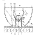
FIG. 2 is a cross section of the simplified configuration of the lighting device according to an embodiment of the present invention; -
FIG. 3 is a simplified oblique view that shown how light is emitted from the lighting device according to an embodiment of the present invention; -
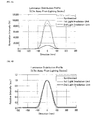
FIG. 4A is a luminance cross sectional graph of the absolute value in the case where light is emitted from the lighting device according to an embodiment at a position that is 0.7 m away from the lighting device; and -
FIG. 4B is a luminance cross sectional graph of the relative value in the case where light is emitted from the lighting device according to an embodiment at a position that is 0.7 m away from the lighting device; and -
FIG. 5A is a luminance cross sectional graph of the absolute value in the case where light is emitted from the lighting device according to an embodiment at a position that is 1.5 m away from the lighting device; and -
FIG. 5B is a luminance cross sectional graph of the relative value in the case where light is emitted from the lighting device according to an embodiment at a position that is 1.5 m away from the lighting device; and -
FIG. 6 is a simplified oblique view of the lighting fixture according to an embodiment of the present invention. - Embodiments for implementing the lighting device and the lighting fixture of the present disclosure will be described below with reference to the accompanying drawings. In the following embodiment of the lighting device and the lighting fixture that embody the technological concept of the present invention are just examples, and unless otherwise specified, the constituent parts discussed in the embodiments are not intended to limit the scope of the present invention.
- Further, constitutions described in examples and the embodiments can be employed in other examples and embodiments. The sizes and the arrangement relationships of the members in each of drawings are occasionally shown exaggerated for ease of explanation.
- The configuration of a
lighting device 1 according to this embodiment will be described through reference toFIGS. 1 and2 . Thelighting device 1 includes a plurality of light irradiation units each includes a light source and a reflecting mirror, the plurality of light irradiation units are located as the optical axis of those are on the same axis and becoming smaller size toward the irradiation target. As shown inFIGS. 1 and2 , thelighting device 1 in this embodiment has a firstlight irradiation unit 10 and a secondlight irradiation unit 20. Thelighting device 1 has atransmissive plate 40 detachably attached to a first irradiation opening OP1 of a first concave reflectingmirror 3 of the firstlight irradiation unit 10. - The first
light irradiation unit 10 in this embodiment has afirst light source 2, the first concavereflecting mirror 3 that reflects light from thefirst light source 2, and afirst base 4 that supports thefirst light source 2 and the first concavereflecting mirror 3. Thefirst light source 2 is located on the optical axis of the first concave reflectingmirror 3, and thefirst light source 2 is located at the focal position of the first concavereflecting mirror 3. - The
first light source 2 is, for example, a light emitting device in which a semiconductor light emitting element is packaged. The light emitting element used in the light emitting device has a semiconductor layer composed of an n-type semiconductor layer, a p-type semiconductor layer, and a light emitting layer. The wavelength of the light emitting element provided to the light emitting device included thisfirst light source 2 can be selected to match the desired emission color or the irradiation target. For instance, to obtain blue light (wavelength of 430 nm to 490 nm) or green light (wavelength of 490 nm to 570 nm), a nitride semiconductor (InXAlYGa1-X-YN (0 ≤ X, 0 ≤ Y, X+Y ≤ 1), ZnSe, GaP, or the like can be used. To obtain red light (wavelength of 620 nm to 750 nm), GaAlAs, AlInGaP, or the like can be used. The composition, emission color, size, and so forth of thefirst light source 2 can be suitably selected as dictated by the intended application and purpose. For example, thefirst light source 2 may have just one light emitting element, or a plurality of light emitting elements arranged on a substrate to create a chip-on-board configuration. - Furthermore, the
first light source 2 may have a pair of positive and negative electrodes on the opposite side from the emission surface, and a pair of positive and negative electrodes on the emission surface and on the opposite side. In the case that light emitting element thefirst light source 2 is mounted in flip-chip manner, it is preferable that either no substrate is provided above the semiconductor layer, or a sapphire or other such light-transmissive substrate is provided, so that enough light can be extracted from the light emitting diode. - The light from the light emitting element may be extracted from the
first light source 2 without changing its color, but a phosphor, quantum dots, or another such wavelength conversion member can be provided to absorb light from the light emitting element and convert it into light of another wavelength. This allows various colors to be obtained. For example, white light, incandescent white, amber color, or other such light that is suited to use for lighting can be easily obtained. Examples of the phosphor the include nitride-based phosphors or oxynitride-based phosphors activated mainly with lanthanoid elements such as europium or cerium, and more specifically, α or β-sialon phosphors activated with europium, various alkaline earth metal nitride silicate phosphors, alkaline earth metal halogen apatite phosphors mainly activated with lanthanoid such as europium or transition metal such as manganese, alkaline earth halo-silicate phosphors, alkaline earth metal silicate phosphors, alkaline earth metal borate halogen phosphors, an alkaline earth metal aluminate salt phosphors, alkaline earth metal silicates salt phosphors, alkaline earth metal sulfides phosphors, alkaline earth metal thiogallate phosphors, alkaline earth metal nitride silicate phosphors, germanate salt phosphors, rare earth aluminates phosphorsmainly activated with lanthanoid elements such as cerium, rare earth silicates phosphors, or organic substance and organic complexes which are mainly activated with lanthanoid element such as europium. - It is particularly favorable to use a YAG phosphor (a yellow phosphor), KSF (K2SiF6:Mn) (a red phosphor), or a β-SiAlON phosphor or a LAG phosphor (a green phosphor), or the like. In addition to these, phosphors having similar performance and effects can also be used as needed. Just one phosphor can be used, or a mixture of two or more types can be used.
- Specific examples of quantum dots that can be used include CdSe, core-shell CdSxSe1-x/ZnS, GaP, InP, AgInS, CuInS, and other such nano-size high-dispersion particles.
- A wavelength conversion member that emits red light improves the visibility of blood vessels and the like by increasing the proportion of red light, so it can be used to advantage in a surgical lighting fixture.
- The
first base 4 in this embodiment supports thefirst light source 2 and the first concave reflectingmirror 3. Thisfirst base 4 here is formed so as to be used as a heat-sink that is capable to remove heat from the firstlight source 2. Thefirst base 4 has a portion to connect the outside of thelighting device 1 and the firstlight source 2 electrically, and support the first concave reflectingmirror 3. As shown inFIGS. 1 and2 , thefirst base 4 is also configured to holdsupport legs 30 that support the secondlight irradiation unit 20. In one example of thefirst base 4, the first concave reflectingmirror 3 is connected to thefirst base 4 by screws, an adhesive agent, welding, or the like, and thesupport legs 30 are also connected to and supported by thefirst base 4. Thefirst base 4 here is formed in a circle in a planer view, but its shape is not limited to this. - The
first base 4 may include a connector, driver, and other such parts that allow power to be supplied from the outside to the firstlight source 2 and allow for the proper drive of the firstlight source 2 described above. - The first concave reflecting
mirror 3 in this embodiment reflects the light from the firstlight source 2 toward the irradiation target. This first concave reflectingmirror 3 here has a firstconcave mirror component 3a that reflects light, and afirst flange 3b that is provided at one end of the firstconcave mirror component 3a. In one example of the first concave reflectingmirror 3, the firstconcave mirror component 3a and thefirst flange 3b are formed integrally from sheet metal. Furthermore, the first concave reflectingmirror 3 has the first irradiation opening OP1 on the side where light is emitted, and a first proximal end opening OQ1 on the side where the firstlight source 2 is mounted, and is configured so that the first proximal end opening OQ1 is formed concentrically on the side of the firstconcave mirror component 3a that is opposite the first irradiation opening OP1. - The first concave reflecting
mirror 3 is formed such that the firstconcave mirror component 3a has a parabolic surface, and is configured so that light emitted from the firstlight source 2 is reflected and irradiated as substantially parallel light. This firstconcave mirror component 3a is formed so as to have a mirror surface by subjecting the surface of its sheet metal to polishing or other such mechanical surface processing, sputtering or other such surface processing, or the like. - The
first flange 3b in this embodiment is formed to match the shape of thefirst base 4. Thisfirst flange 3b may be used to connect the first concave reflectingmirror 3 to thefirst base 4, and may be large enough to allow connection by screws or the like. Thefirst flange 3b in this embodiment has grooves formed on its side that is opposite thefirst base 4, so as to sandwich thesupport legs 30 between itself and thefirst base 4. Therefore, the first concave reflectingmirror 3 in this embodiment is fixed on thefirst base 4 with thesupport legs 30 by connecting thefirst flange 3b and thefirst base 4 by screws or the like in a state in which connectingleg components 31 of thesupport legs 30 are put into the grooves in thefirst flange 3b. Furthermore, in this embodiment thefirst flange 3b is formed in a band shape around the outside of thefirst base 4, but there are no particular restrictions on the size, shape, and so forth thereof so long as it can be supported on thefirst base 4. Also, thefirst flange 3b here is configured integrally with the firstconcave mirror component 3 a, but it may be formed separately and then connected to the firstconcave mirror component 3a. - As shown in
FIG. 1 , thesupport legs 30 in this embodiment are used to support the secondlight irradiation unit 20. Thesupport legs 30 here also serve to block directly incident light from the secondlight irradiation unit 20. More precisely, thesupport legs 30 have the connectingleg components 31 supported by thefirst base 4,upright leg components 32 formed at one end on the irradiation target side of the connectingleg components 31,horizontal leg components 33 formed at one end of theseupright leg components 32,vertical leg components 34 formed at one end of thesehorizontal leg components 33, and a light blocker 35 (second light blocker) formed at one end of thesevertical leg components 34. - The connecting
leg components 31 are, for example, such that four linear members are disposed equidistantly at positions opposing thefirst base 4 in a planar view. These connectingleg components 31 are provided so that their ends are at locations where theupright leg components 32 can rise up through the first proximal end opening OQ1. There are no particular restrictions on the shape, size, length, and so forth of the connectingleg components 31, so as long as they can be supported on thefirst base 4. The connectingleg components 31 may have screw holes formed in them and they are removably attached to thefirst base 4 by screws. - The
upright leg components 32 in this embodiment are used to dispose the secondlight irradiation unit 20 at the predetermined height. Theseupright leg components 32 are formed integrally and contiguous with the connectingleg components 31 by bending one end of the connectingleg components 31 at a specific angle (such as 90 degrees), for example. Theupright leg components 32 are formed so as to rise up through the first proximal end opening OQ1 of the firstlight irradiation unit 10 toward the first irradiation opening OP1. Because theupright leg components 32 are disposed at positions where they may block part of the light from the firstlight source 2, they are preferably formed from strips or wires of metal or the like that are as thin as possible so that their surface area that blocks light will be smaller, but they will be strong enough to support the secondlight irradiation unit 20. Also, theupright leg components 32 here are configured so that the side surfaces of asecond base 14 of the secondlight irradiation unit 20 is connected to and supported by the upper ends thereof. - The
horizontal leg components 33 in this embodiment are formed integrally and contiguous with theupright leg components 32 by bending the upper ends of theupright leg components 32 at a specific angle (for example, 90 degrees). Thesehorizontal leg components 33 are a connection portion used to form thevertical leg components 34 so that they rise up through a second proximal end opening OQ2 of the secondlight irradiation unit 20 toward a second irradiation opening OP2. The upper surface of thesecond base 14 of the secondlight irradiation unit 20 may be connected to thesehorizontal leg components 33. - The
vertical leg components 34 in this embodiment are used to support thelight blocker 35, which blocks directly incident light from a secondlight source 12. Thesevertical leg components 34 here are formed integrally and contiguous with thehorizontal leg components 33 by bending one end of thehorizontal leg components 33 at a specific angle (for example, 90 degrees). Thevertical leg components 34 are formed so as to rise up through the second proximal end opening OQ2 of the secondlight irradiation unit 20 toward the second irradiation opening OP2. Because thevertical leg components 34 are disposed at positions where they block part of the light from the secondlight source 12, they are preferably formed from strips or wires of metal or the like that are as thin as possible so that their surface area that blocks light will be smaller, but they will be strong enough to support thelight blocker 35. - The
light blocker 35 in this embodiment is used to shield the irradiation target from directly incident light from the secondlight source 12. Thislight blocker 35 here is formed integrally and contiguous with one side of thevertical leg components 34. As an example, thislight blocker 35 is formed from a circular piece of sheet metal. The surface area of thelight blocker 35 is large enough to allow the directly incident light of the secondlight source 12 to be blocked. - The
support legs 30 described above are formed, for example, by punching out sheet metal and bending it so as to integrate thevertical leg components 34, thehorizontal leg components 33, theupright leg components 32, and the connectingleg components 31 and thelight blocker 35. Accordingly, thesupport legs 30 including screw holes can be easily formed by punching out and bending the material. - As shown in
FIGS. 1 and2 , the secondlight irradiation unit 20 in this embodiment is formed smaller than the firstlight irradiation unit 10, and the secondlight source 12 and a second concave reflectingmirror 13 are disposed along the optical axis so that their optical axis will be the same as the optical axis of the firstlight source 2 and the first concave reflectingmirror 3 of the firstlight irradiation unit 10. Also, the second concave reflectingmirror 13 of the secondlight irradiation unit 20 is disposed so that its opening direction coincides with the opening direction of the first concave reflectingmirror 3. Also, thesecond base 14 is located on thesupport legs 30 so that it will be at a position where it blocks directly incident light from the firstlight irradiation unit 10. Furthermore, the secondlight irradiation unit 20 is located on thesupport legs 30 so that it will be more to the inside than the open end of the first concave reflectingmirror 3. This secondlight irradiation unit 20 can be used to adjust the color temperature with respect to the firstlight irradiation unit 10. - The second
light irradiation unit 20 has the secondlight source 12, the second concave reflectingmirror 13 that reflects the light from this secondlight source 12 toward the irradiation target, and thesecond base 14 that supports the secondlight source 12 and the second concave reflectingmirror 13. The second light irradiation unit 20 (the second base 14) is disposed more to the light irradiation direction side than the firstlight source 2, at a position opposite the firstlight source 2 of the firstlight irradiation unit 10, and here has the role of a light blocker (first light blocker) that blocks directly incident light going from the firstlight source 2 toward the irradiation target. - The second
light source 12 and the second concave reflectingmirror 13 in this embodiment are formed in substantially equivalent shapes with respect to the shapes of the firstlight source 2 and the first concave reflectingmirror 3. The secondlight source 12 has substantially the same structure as the firstlight source 2 described above, and is configured to have a different emission color from that of the firstlight source 2. The secondlight source 12 is mounted on thesecond base 14, which can function as a heat sink, so as to be at the focal position of the second concave reflectingmirror 13. The size of the light irradiation surface portion of the secondlight source 12 is smaller than the light irradiation surface portion of the firstlight source 2. The second concave reflectingmirror 13 has a secondconcave mirror component 13a and asecond flange 13b, and is smaller in size than the first concave reflectingmirror 3. The secondconcave mirror component 13a has a parabolic surface, just as is the firstconcave mirror component 3a. Thesecond flange 13b has the same configuration as thefirst flange 3b, and only its size is different. - The second
light irradiation unit 20 is configured so that the secondlight source 12 is provided to thesecond base 14 located in the second proximal end opening OQ2 of the second concave reflectingmirror 13 and irradiates light. The light is reflected by the secondconcave mirror component 13a and directed at the irradiation target from the second irradiation opening OP2. The directly incident light from the secondlight source 12 is blocked by thelight blocker 35 disposed at location opposite the secondlight source 12. - The term "equivalent shape" in the present specification means the shapes of the first
light irradiation unit 10 and the secondlight irradiation unit 20 are similar and the percentage of the correspondence of the relative intensity of light from the firstlight source 2 and the secondlight source 12 at the irradiation face (the irradiation target) is at least 90%, in the case where 100% means the values at full width at half maximum match. The term "substantially equivalent shape" means the shapes of the firstlight irradiation unit 10 and the secondlight irradiation unit 20 in the case where the above-mentioned value is at least 70%. Therefore, although it is preferable for the shapes, etc., to substantially match even though the sizes of the first concave reflectingmirror 3 and the second concave reflectingmirror 13 are different, the match does not need to be perfect. Also, it is preferable for the shape, etc., to match in the portions of the light irradiation surface where the firstlight source 2 and the secondlight source 12 are also in a different size relation, but the match does not need to be perfect. - Also, saying that the second concave reflecting
mirror 13 is smaller than the first concave reflectingmirror 3 means, for example, that the diameter of the second irradiation opening OP2 is less than 60% of the diameter of the first irradiation opening OP1. In the case where efficiency of adjusting the color temperature and irradiation intensity is taken into account, 50% or less is preferable, and 40% or less is even better. - Further, in the case where the second
light irradiation unit 20 is housed in the firstlight irradiation unit 10, the entire secondlight irradiation unit 20 is preferably located on the inside of the first irradiation opening OP1 of the firstlight irradiation unit 10, but part of it (such as the second base 14) can be located on the inside of the first irradiation opening OP1 of the firstlight irradiation unit 10, or more than half of it may be located on the inside of the first irradiation opening OP1. In the case that the entire secondlight irradiation unit 20 is not disposed on the inside of the firstlight irradiation unit 10, the shape of thetransmissive plate 40 described below may be changed so that its middle protrudes out. - As shown in
FIGS. 1 and2 , thetransmissive plate 40 may be attached to the first irradiation opening OP1 of the first concave reflectingmirror 3 of the firstlight irradiation unit 10. Thistransmissive plate 40 can be formed from a transparent plastic, transparent glass, or another such material that will transmit the light from the firstlight source 2 and the secondlight source 12. Thistransmissive plate 40 may be used to protect a reflecting surface and thelight sources - As shown in
FIG. 2 , thelighting device 1 having the configuration described above can irradiate an irradiation target with light produced by the firstlight irradiation unit 10 and the secondlight irradiation unit 20, in a state in which color unevenness is unlikely to occur. Also, with thelighting device 1, since the secondlight irradiation unit 20 is disposed on the inside of the firstlight irradiation unit 10, the size in the depth direction can be kept to a minimum. As shown inFIG. 3 , thelighting device 1 irradiates a first irradiation surface SA1 or a second irradiation surface SA2 with light, the light will be in the following state. - As shown in
FIG. 2 , with thelighting device 1, light emitted from the firstlight source 2 of the firstlight irradiation unit 10 and reflected to the firstconcave mirror component 3a, and light emitted from the secondlight source 12 of the secondlight irradiation unit 20 and reflected to the secondconcave mirror component 13a are directed at the irradiation target. When light is emitted from thelighting device 1, directly incident light from the firstlight source 2 of the firstlight irradiation unit 10 is blocked by thesecond base 14 of the secondlight irradiation unit 20, and directly incident light from the secondlight source 12 of the secondlight irradiation unit 20 is blocked by thelight blocker 35. - Therefore, with the
lighting device 1, as irradiation light, directly incident light which cause glare can be blocked, and the irradiation target can be irradiated with light that combines parallel light from the firstconcave mirror component 3a and the secondconcave mirror component 13a. Accordingly, with thelighting device 1, for example, a light emitting device that is capable to emit white light is used as the firstlight source 2, and a light emitting device that is capable to a different color light from that of the firstlight source 2, such as yellow light, yellowish white light, or the like, is used as the secondlight source 12, which allows the color of the light obtained from thelighting device 1 to be easily adjusted. For instance, thelighting device 1 can be adjusted so that the target is seen more clearly. Furthermore, the emission colors of the firstlight source 2 and the secondlight source 12 may be selected so that the color temperature of light from the firstlight source 2 is adjusted with light emitted from the secondlight source 12. For example, in the case that the color temperature of the secondlight source 12 is lower than the color temperature of the firstlight source 2, light with the desired color temperature can be obtained between the firstlight source 2 and the secondlight source 12 by adjusting the amount of light from the firstlight source 2 and the amount of light from the secondlight source 12. - Also, with the
lighting device 1, even though the distance to the irradiation target is changed, since the firstlight irradiation unit 10 and the secondlight irradiation unit 20 are formed in substantially equivalent shapes and disposed on the same optical axis, the luminance distribution at the irradiation surface will be substantially the same, making it less likely that there will be color unevenness in the combined light. - This state in which color unevenness is unlikely to occur will be described through reference to
FIGS. 3 ,4A ,4B ,5A and 5B . - With the
lighting device 1, the luminance in an absolute luminance cross section and the relative intensity in a relative luminance cross section are measured in the case where the distance to the first irradiation surface SA1 (a specific distance) shown inFIG. 3 was 0.7 m in the case where light was emitted, for example. With thelighting device 1, the values shown inFIG. 4A to FIG. 5B are measured, the firstlight irradiation unit 10 and the secondlight irradiation unit 20 are configured as follows, for example. The firstlight source 2 is a white (4500 K) LED light source with a 23.0 mm emission surface, and the secondlight source 12 is an amber (3800 K) LED light source with an 8.7 mm emission surface. The first concave reflectingmirror 3 of the firstlight irradiation unit 10 has a parabolic mirror surface in which a diameter of the first irradiation opening OP1 is a diameter of 160 mm, and a diameter of the first proximal end opening OQ1 is 60 mm. The concave reflectingmirror 13 of the secondlight irradiation unit 20 has a parabolic mirror surface in which a diameter of the second irradiation opening OP2 is 58 mm and a diameter of the second proximal end opening OQ2 is 36 mm. - As shown in
FIG. 4A , in an absolute luminance cross section, with an irradiation surface distribution cross section (circular distribution cross section), light is emitted over a range of about -100 to 100 mm, with the center of the emitted light at 0 mm. In an irradiation surface distribution cross section, the luminance with the firstlight irradiation unit 10 and the secondlight irradiation unit 20 is be substantially symmetrical about the center. Further, as shown inFIG. 4B , the relative intensity in a relative luminance cross section gives substantially matching values for the firstlight irradiation unit 10 and the secondlight irradiation unit 20. Thus, because thelighting device 1 has the firstlight irradiation unit 10 and the secondlight irradiation unit 20 that are configured as substantially equivalent shapes with the same optical axis, the light emitted from thelighting device 1 will relatively have substantially the same luminance distributions at the irradiation surface, so this can be considered a state in which color unevenness is unlikely to occur in the combined light. - As shown in
FIG. 3 , with thelighting device 1, the luminance in an absolute luminance cross section and the relative intensity in a relative luminance cross section are measured when the distance to the second irradiation surface SA2 (a specific distance) was 1.5 m in the case where light is emitted, for example. - As shown in
FIG. 5A , in an absolute luminance cross section, with an irradiation surface distribution cross section (circular distribution cross section), light is emitted over a range of about -200 to 200 mm, with the center of the emitted light at 0 mm. In an irradiation surface distribution cross section, the luminance with the firstlight irradiation unit 10 and the secondlight irradiation unit 20 is substantially symmetrical about the center. Further, as shown inFIG. 5B , the relative intensity in a relative luminance cross section gives substantially matching values for the firstlight irradiation unit 10 and the secondlight irradiation unit 20. Thus, because thelighting device 1 has the firstlight irradiation unit 10 and the secondlight irradiation unit 20 that are configured as substantially equivalent shapes with the same optical axis, the light emitted from thelighting device 1 will relatively have substantially the same luminance distributions at the irradiation surface even though the distance changes from 0.7 m to 1.5 m, so this can be considered a state in which color unevenness is unlikely to occur in the combined light. - As described above, the
lighting device 1 is configured so that color unevenness will be unlikely to occur at the irradiation surface even when the position of the irradiation target is changed. Accordingly, with thelighting device 1, handling is easy, adjustment the firstlight source 2 and the secondlight source 12 may not be required in the case where the distance to the irradiation target is changed, and a state of uniform luminance distribution up to a preset irradiation target can be maintained even when the irradiation distance changes. Therefore, thelighting device 1 is suited to lighting fixtures used in the medical field, for example. - As shown in
FIG. 6 , a case of applying thelighting device 1 to alighting fixture 100 will now be described. - As shown in
FIG. 6 , thelighting fixture 100 in this embodiment is applied to perform surgery or the like in a medical facility. With thislighting fixture 100, it may be necessary in the course of surgery to change the distance to the site on the patient (the irradiation target). In this case, it is necessary that color unevenness is unlikely to occur even when thelighting fixture 100 is moved from its preset position and the distance to the irradiation target is changed. - The
lighting fixture 100 may be configured so that it can be moved to a position where light can be directed toward the irradiation target, and here it has a lightingfixture support base 101, asupport arm 102 provided above this lightingfixture support base 101, a lightingfixture light source 103 provided to the distal end of thissupport arm 102, ahandle bar 104 for adjusting the position of this lightingfixture light source 103, and a transmissive cover provided so as to protect the lightingfixture light source 103. - The lighting
fixture light source 103 has a plurality of thelighting devices 1 described above arranged within a lighting fixture shade-like frame 105 via aspacer 106, for example. Thelighting devices 1 may be spaced apart from one another, or may be disposed adjacent to one another. Also, thesupport arm 102 here is configured to have a rotation unit that changes the angle or direction at a plurality of joint positions in the lengthwise direction. - With the
lighting fixture 100 described above, the lightingfixture support base 101 is disposed so that light irradiates a preset position, and the light from the lightingfixture light source 103 is emitted toward the irradiation target in a state in which the angle of thesupport arm 102 is set. The light emitted from thelighting fixture 100 becomes combined light at the position of the irradiation target, and the irradiation target is irradiated in a state in which color unevenness is unlikely to occur. Also, with thelighting fixture 100, in the case that the position of the lightingfixture light source 103 is changed, thehandle bar 104 is pushed or pulled to move the portions that serve as the joints of thesupport arm 102, allowing adjustment that changes the position of the lightingfixture light source 103. Also, alighting fixture 100 that casts no shadow on the irradiated site (called a shadow-less light, etc.) can be created by varying the angles of the light from a plurality of lighting devices. - Even when the distance to the irradiation target is changed from the preset position, the light emitted from the lighting
fixture light source 103 will still have the same luminance distribution as shown inFIGS. 4A and5A and inFIGS. 4B and5B , so color unevenness will be unlikely to occur. Therefore, this is convenient for performing surgery, such as being able to easily find the position of a patient's vein or artery (examples of the irradiation target). With thelighting fixture 100, since the colors of the firstlight source 2 and the secondlight source 12 are different in the plurality oflighting devices 1 respectively. - As described above, with the
lighting device 1 and thelighting fixture 100 disclosed herein, since the firstlight irradiation unit 10 and the secondlight irradiation unit 20 are mounted in substantially equivalent shapes on a single optical axis, color unevenness will be unlikely to occur in combined light since there is no change in the luminance distribution even though the distance to the irradiation target is changed, so the irradiation target can be properly illuminated. - With the
lighting device 1 and thelighting fixture 100, the firstconcave mirror component 3a and the secondconcave mirror component 13a are described as being parabolic surfaces, but they may instead be pseudo-parabolic surfaces in which cross sectional shapes along the optical axis of a concave mirror are connected straight lines, for example. Also, the emission colors used by the firstlight source 2 and the secondlight source 12 may be any color other than white or yellow. - Also, in the case that the first
light source 2 and the secondlight source 12 are positioned at a specific location of thefirst base 4 or thesecond base 14, they may be connected via solder, a connector, or an anisotropic conduction member. Furthermore, the firstlight source 2 and the secondlight source 12 may be configured to cover a transmissive member (such as a sealing resin, etc.). In the case that the transmissive member is provided, it may contain a phosphor, a colorant, a light diffuser, a filler, or the like in order to convert the wavelength or improve light extraction efficiency, as desired. - The
first flange 3b described above is formed so as to be evenly contiguous with the outer periphery of thefirst base 4, but thefirst flange 3b may instead be formed so as to be intermittently contiguous with the firstconcave mirror component 3a, so that the connectingleg components 31 of thesupport legs 30 are exposed from thefirst flange 3b. Also, thesecond flange 13b described above is formed so as to be evenly contiguous with the outer periphery of thesecond base 14, but thesecond flange 13b may instead be formed so as to be intermittently contiguous with the secondconcave mirror component 13a, so that thehorizontal leg components 33 of thesupport legs 30 are exposed from thesecond flange 13b. - Also, the angle of the
upright leg components 32 may be set according to the outer peripheral shape of thesecond base 14, this angle can be greater than or less than 90 degrees to provide an inclination angle. Furthermore, an inclination angle may be provided to thevertical leg components 34 so that this angle is greater than or less than 90 degrees, depending on the size of thelight blocker 35. - Further, screw holes may be formed in the upper ends of the
upright leg components 32, so that thesecond base 14 of the secondlight irradiation unit 20 is supported by screws. - With the second
light irradiation unit 20, a configuration described above is in which thelight blocker 35 that blocked directly incident light is provided to thesupport legs 30, but the configuration may instead be such that a light blocking film or plate that blocks directly incident light of the secondlight source 12 is mounted in the center of thetransmissive plate 40. - Also, the
support legs 30 described above include four legs that reached thelight blocker 35, but are not limited to this configuration, and may be three or two, etc. - Further, the first light blocker that blocks directly incident light of the first
light irradiation unit 10 is not limited to a configuration in which it is also used for the second light irradiation unit 20 (or the second base 14), and may instead be constituted by a separate light blocking plate or other such member. - Moreover, the
lighting device 1 described above has the firstlight irradiation unit 10 and the secondlight irradiation unit 20, but this is not the only option, and may have a third light irradiation unit that is smaller than the secondlight irradiation unit 20, in the same relation as that of the firstlight irradiation unit 10 and the secondlight irradiation unit 20, for example.
Claims (13)
- A lighting device, comprising:a first light irradiation unit including a first concave reflecting mirror and a first light source provided within the first concave reflecting mirror; anda second light irradiation unit including a second concave reflecting mirror that is smaller than the first concave reflecting mirror and a second light source provided within the second concave reflecting mirror, the second light irradiation unit being disposed more to the light irradiation direction side than the first light source, and being disposed so that the optical axes of the first concave reflecting mirror and the second concave reflecting mirror are the same.
- The lighting device according to Claim 1, wherein a plurality of the light irradiation units having concave reflecting mirrors and light sources are formed in substantially similar shapes.
- The lighting device according to Claim 1 or 2, wherein the second light irradiation unit is disposed within the concave reflecting mirror of the first light irradiation unit.
- The lighting device according to any one of Claims 1 to 3, wherein the second light irradiation unit is disposed at a position opposite the first light source of the first light irradiation unit, and part of the light emitted from the first light source is blocked by the second light irradiation unit.
- The lighting device according to any one of Claims 1 to 4, wherein the second light irradiation unit is configured to have a different emission color from that of the first light irradiation unit.
- The lighting device according to any one of Claims 1 to 5, wherein the second light irradiation unit irradiates light to adjust the color temperature with respect to the first light irradiation unit.
- The lighting device according to any one of Claims 1 to 6, wherein
the first concave reflecting mirror has a first concave mirror component having a mirror surface. - The lighting device according to Claim 7 wherein
the first concave mirror component has a parabolic surface. - The lighting device according to Claim 7, wherein
the first concave mirror component has a pseudo-parabolic surface. - The lighting device according to any one of Claims 1 to 9, wherein
the first concave reflecting mirror has a first irradiation opening, and a transmissive plate attached to the first irradiation opening. - The lighting device according to any one of Claims 1 to 10, wherein
the first light source is located at a focal position of the first concave reflecting mirror. - The lighting device according to any one of Claims 1 to 11, wherein
the entire second light irradiation unit is located on the inside of the first light irradiation unit. - A lighting fixture, comprising
a lighting fixture light source in which a plurality of lighting devices according to any one of Claims 1 to 12 are mounted in a row.
Applications Claiming Priority (1)
| Application Number | Priority Date | Filing Date | Title |
|---|---|---|---|
| JP2014202190A JP6484981B2 (en) | 2014-09-30 | 2014-09-30 | Lighting device and lamp |
Publications (2)
| Publication Number | Publication Date |
|---|---|
| EP3002507A1 true EP3002507A1 (en) | 2016-04-06 |
| EP3002507B1 EP3002507B1 (en) | 2019-06-05 |
Family
ID=54260616
Family Applications (1)
| Application Number | Title | Priority Date | Filing Date |
|---|---|---|---|
| EP15187341.1A Active EP3002507B1 (en) | 2014-09-30 | 2015-09-29 | Lighting device and lighting fixture |
Country Status (5)
| Country | Link |
|---|---|
| US (1) | US9784434B2 (en) |
| EP (1) | EP3002507B1 (en) |
| JP (1) | JP6484981B2 (en) |
| CN (1) | CN105465618B (en) |
| TW (1) | TWI687627B (en) |
Cited By (4)
| Publication number | Priority date | Publication date | Assignee | Title |
|---|---|---|---|---|
| WO2020094915A1 (en) * | 2018-11-07 | 2020-05-14 | Ledil Oy | A lighting system |
| DE102020122209A1 (en) | 2020-08-25 | 2022-03-03 | Frowein Ezh Gmbh | surgical light |
| CN116717752A (en) * | 2023-06-20 | 2023-09-08 | 山东新华医疗器械股份有限公司 | A lighting device and operating light using reflective structure |
| WO2025003063A1 (en) * | 2023-06-27 | 2025-01-02 | Signify Holding B.V. | Lighting device |
Families Citing this family (8)
| Publication number | Priority date | Publication date | Assignee | Title |
|---|---|---|---|---|
| EP3351850B1 (en) * | 2015-09-17 | 2020-09-09 | Furukawa Electric Co., Ltd. | Led lighting device, and method for extracting light of led lighting device |
| US10533732B2 (en) * | 2016-01-20 | 2020-01-14 | National University Corporation Shimane University | Headlamp for healthcare workers |
| WO2018072633A1 (en) * | 2016-10-17 | 2018-04-26 | 欧普照明股份有限公司 | Lighting device |
| US10363114B2 (en) | 2016-11-01 | 2019-07-30 | American Sterilizer Company | Aiming and status indicator system for surgical lightheads and cameras |
| GB2557278B (en) * | 2016-12-02 | 2019-01-09 | Disruptive Marketing Ltd | Halo lighting unit |
| US11225299B2 (en) * | 2019-07-31 | 2022-01-18 | Niterider Technical Lighting & Video Systems, Inc. | Light assembly |
| US11529209B2 (en) | 2021-04-16 | 2022-12-20 | Augustine Biomedical + Design, LLC | Aerodynamic surgical light and boom systems |
| US11644187B2 (en) | 2021-04-16 | 2023-05-09 | Augustine Biomedical + Design, LLC | Aerodynamic surgical light and boom systems |
Citations (6)
| Publication number | Priority date | Publication date | Assignee | Title |
|---|---|---|---|---|
| GB686620A (en) * | 1949-10-08 | 1953-01-28 | Friedrich Nallinger | Improvements relating to lamps for vehicles |
| US20060109650A1 (en) * | 2004-11-19 | 2006-05-25 | Dräger Medical AG & Co. KGaA | Operating room light fixture |
| JP2006318995A (en) | 2005-05-10 | 2006-11-24 | Iwasaki Electric Co Ltd | Multilayer light emitting diode device and reflective light emitting diode unit |
| US7431486B2 (en) * | 2006-08-22 | 2008-10-07 | Philips Lumileds Lighting Company, Llc | LED assembly for rear lamps in an automobile |
| US7677760B2 (en) * | 2004-01-14 | 2010-03-16 | Simon Jerome H | Efficient and uniformly distributed illumination from multiple source luminaires |
| US20100079995A1 (en) * | 2005-12-07 | 2010-04-01 | Simon Jerome H | Luminaires and optics for control and distribution of multiple quasi point source light sources such as leds |
Family Cites Families (24)
| Publication number | Priority date | Publication date | Assignee | Title |
|---|---|---|---|---|
| US2740104A (en) * | 1949-10-08 | 1956-03-27 | Friedrich K H Nallinger | Combination tail and signal light for vehicles |
| US2676312A (en) * | 1953-06-04 | 1954-04-20 | Dillon John Roy | Catadioptric signal light |
| NO301191B1 (en) * | 1993-05-13 | 1997-09-22 | Cargoscan As | Device for measuring object dimensions |
| JPH0799343A (en) | 1993-09-27 | 1995-04-11 | Iwasaki Electric Co Ltd | Light emitting diode and stacked light emitting diode |
| JPH09116187A (en) | 1995-10-16 | 1997-05-02 | Stanley Electric Co Ltd | Perfect coaxial composite optical device |
| DE19956337B4 (en) * | 1999-11-23 | 2004-11-25 | Heraeus Med Gmbh | Luminaire, in particular surgical light, with at least two electric lamps |
| JP2002360514A (en) | 2001-06-08 | 2002-12-17 | Pentax Corp | Light source device and processor for electronic endoscope |
| US20040032739A1 (en) * | 2002-08-15 | 2004-02-19 | Johanson Walter A. | Illumination tubes, illumination devices and methods of forming same |
| EP1568938B1 (en) * | 2004-02-28 | 2006-09-27 | TRUMPF Kreuzer Medizin Systeme GmbH + Co. KG | Surgical lamp and method of illumination of an operating theatre |
| US7021806B2 (en) * | 2004-05-24 | 2006-04-04 | General Motors Corporation | Illuminated displays |
| DE102004055838B4 (en) * | 2004-11-19 | 2011-07-28 | Dräger Medical GmbH, 23558 | Operating light and control device |
| WO2006120978A1 (en) | 2005-05-10 | 2006-11-16 | Iwasaki Electric Co., Ltd. | Projector device, multilayer light-emitting diode device, and reflective light-emitting diode unit |
| TWM281835U (en) * | 2005-07-14 | 2005-12-01 | Depo Auto Parts Ind Co Ltd | Improved structure of car headlight rim |
| US7369329B2 (en) * | 2006-05-04 | 2008-05-06 | Philips Lumileds Lighting Company, Llc | Producing distinguishable light in the presence of ambient light |
| US20090135606A1 (en) * | 2007-11-28 | 2009-05-28 | Caltraco International Limited | Multi-reflector mechanism for a led light source |
| US8083364B2 (en) * | 2008-12-29 | 2011-12-27 | Osram Sylvania Inc. | Remote phosphor LED illumination system |
| JP2010182583A (en) | 2009-02-06 | 2010-08-19 | Seiko Epson Corp | Light source device, and projector |
| JP2010198862A (en) * | 2009-02-24 | 2010-09-09 | Panasonic Electric Works Co Ltd | Illumination fixture |
| CN201589169U (en) * | 2010-01-25 | 2010-09-22 | 张方涛 | Bifocal-lens motorcycle headlamp |
| RU2594487C2 (en) * | 2010-04-28 | 2016-08-20 | Конинклейке Филипс Электроникс Н.В. | Defocused optics for multichip light-emitting diode |
| JP5719127B2 (en) * | 2010-07-27 | 2015-05-13 | 株式会社モデュレックス | Indoor lighting fixture with LED light source |
| US10451251B2 (en) * | 2010-08-02 | 2019-10-22 | Ideal Industries Lighting, LLC | Solid state lamp with light directing optics and diffuser |
| CN103574329B (en) * | 2012-07-31 | 2017-06-13 | 海洋王(东莞)照明科技有限公司 | Light fixture and its reflecting assembly |
| CN203223822U (en) * | 2013-04-11 | 2013-10-02 | 上海吉顺医疗器械制造有限公司 | Secondary reflection type LED operation shadowless lamp |
-
2014
- 2014-09-30 JP JP2014202190A patent/JP6484981B2/en active Active
-
2015
- 2015-09-28 US US14/867,121 patent/US9784434B2/en active Active
- 2015-09-29 EP EP15187341.1A patent/EP3002507B1/en active Active
- 2015-09-29 CN CN201510631825.8A patent/CN105465618B/en active Active
- 2015-09-30 TW TW104132264A patent/TWI687627B/en active
Patent Citations (6)
| Publication number | Priority date | Publication date | Assignee | Title |
|---|---|---|---|---|
| GB686620A (en) * | 1949-10-08 | 1953-01-28 | Friedrich Nallinger | Improvements relating to lamps for vehicles |
| US7677760B2 (en) * | 2004-01-14 | 2010-03-16 | Simon Jerome H | Efficient and uniformly distributed illumination from multiple source luminaires |
| US20060109650A1 (en) * | 2004-11-19 | 2006-05-25 | Dräger Medical AG & Co. KGaA | Operating room light fixture |
| JP2006318995A (en) | 2005-05-10 | 2006-11-24 | Iwasaki Electric Co Ltd | Multilayer light emitting diode device and reflective light emitting diode unit |
| US20100079995A1 (en) * | 2005-12-07 | 2010-04-01 | Simon Jerome H | Luminaires and optics for control and distribution of multiple quasi point source light sources such as leds |
| US7431486B2 (en) * | 2006-08-22 | 2008-10-07 | Philips Lumileds Lighting Company, Llc | LED assembly for rear lamps in an automobile |
Cited By (4)
| Publication number | Priority date | Publication date | Assignee | Title |
|---|---|---|---|---|
| WO2020094915A1 (en) * | 2018-11-07 | 2020-05-14 | Ledil Oy | A lighting system |
| DE102020122209A1 (en) | 2020-08-25 | 2022-03-03 | Frowein Ezh Gmbh | surgical light |
| CN116717752A (en) * | 2023-06-20 | 2023-09-08 | 山东新华医疗器械股份有限公司 | A lighting device and operating light using reflective structure |
| WO2025003063A1 (en) * | 2023-06-27 | 2025-01-02 | Signify Holding B.V. | Lighting device |
Also Published As
| Publication number | Publication date |
|---|---|
| JP6484981B2 (en) | 2019-03-20 |
| TWI687627B (en) | 2020-03-11 |
| US9784434B2 (en) | 2017-10-10 |
| JP2016072145A (en) | 2016-05-09 |
| US20160091170A1 (en) | 2016-03-31 |
| CN105465618B (en) | 2020-06-30 |
| EP3002507B1 (en) | 2019-06-05 |
| TW201621216A (en) | 2016-06-16 |
| CN105465618A (en) | 2016-04-06 |
Similar Documents
| Publication | Publication Date | Title |
|---|---|---|
| EP3002507B1 (en) | Lighting device and lighting fixture | |
| US12336864B1 (en) | Illuminating surgical device | |
| US8672523B2 (en) | Light emitter with predefined angular color point distribution | |
| CN101238326B (en) | Operating lamp | |
| EP1847762B1 (en) | Compact lighting device, in particular for use in a dental lamp | |
| CN103299422B (en) | There is the long-distance fluorescent powder LED matrix of Broadband emission and controllable color | |
| US20160228227A1 (en) | Three-dimensional curing light | |
| JP5918751B2 (en) | Defocusing optics for multichip LEDs | |
| US7450028B2 (en) | Led operation light | |
| CN101997265A (en) | Light source device | |
| WO2011068555A1 (en) | Light fixture using near uv solid state device and remote semiconductor nanophosphors to produce white light | |
| US20120106145A1 (en) | Operating light and a process for lighting an operating table by means of an operating light | |
| CN103363345A (en) | Light emitting device, and illumination apparatus and luminaire using same | |
| JP2016515767A (en) | Light emitting assembly and method with spectral shift reflection | |
| US9605814B2 (en) | Lighting module | |
| US8278806B1 (en) | LED reflector lamp | |
| JP2015204291A (en) | Medical lighting fixture | |
| JP5280502B2 (en) | Light source device | |
| RU2657242C2 (en) | Lighting device and method of reducing uncomfortable glare | |
| JP4508034B2 (en) | Lighting equipment using white LED | |
| TW201810603A (en) | High brightness white light emitting diode light source | |
| JP6485282B2 (en) | Vehicle lighting device | |
| CN203215409U (en) | Luminous unit and illuminating device | |
| CN202708676U (en) | surgical light | |
| TWM380423U (en) | Lighting |
Legal Events
| Date | Code | Title | Description |
|---|---|---|---|
| PUAI | Public reference made under article 153(3) epc to a published international application that has entered the european phase |
Free format text: ORIGINAL CODE: 0009012 |
|
| AK | Designated contracting states |
Kind code of ref document: A1 Designated state(s): AL AT BE BG CH CY CZ DE DK EE ES FI FR GB GR HR HU IE IS IT LI LT LU LV MC MK MT NL NO PL PT RO RS SE SI SK SM TR |
|
| AX | Request for extension of the european patent |
Extension state: BA ME |
|
| 17P | Request for examination filed |
Effective date: 20161006 |
|
| RBV | Designated contracting states (corrected) |
Designated state(s): AL AT BE BG CH CY CZ DE DK EE ES FI FR GB GR HR HU IE IS IT LI LT LU LV MC MK MT NL NO PL PT RO RS SE SI SK SM TR |
|
| STAA | Information on the status of an ep patent application or granted ep patent |
Free format text: STATUS: EXAMINATION IS IN PROGRESS |
|
| 17Q | First examination report despatched |
Effective date: 20170424 |
|
| GRAP | Despatch of communication of intention to grant a patent |
Free format text: ORIGINAL CODE: EPIDOSNIGR1 |
|
| STAA | Information on the status of an ep patent application or granted ep patent |
Free format text: STATUS: GRANT OF PATENT IS INTENDED |
|
| RIC1 | Information provided on ipc code assigned before grant |
Ipc: F21Y 111/00 20160101ALN20181121BHEP Ipc: F21V 7/00 20060101AFI20181121BHEP Ipc: F21V 7/06 20060101ALI20181121BHEP Ipc: F21Y 115/10 20160101ALN20181121BHEP Ipc: F21W 131/205 20060101ALN20181121BHEP Ipc: F21Y 113/00 20160101ALN20181121BHEP |
|
| INTG | Intention to grant announced |
Effective date: 20181219 |
|
| GRAS | Grant fee paid |
Free format text: ORIGINAL CODE: EPIDOSNIGR3 |
|
| GRAA | (expected) grant |
Free format text: ORIGINAL CODE: 0009210 |
|
| STAA | Information on the status of an ep patent application or granted ep patent |
Free format text: STATUS: THE PATENT HAS BEEN GRANTED |
|
| AK | Designated contracting states |
Kind code of ref document: B1 Designated state(s): AL AT BE BG CH CY CZ DE DK EE ES FI FR GB GR HR HU IE IS IT LI LT LU LV MC MK MT NL NO PL PT RO RS SE SI SK SM TR |
|
| REG | Reference to a national code |
Ref country code: GB Ref legal event code: FG4D |
|
| REG | Reference to a national code |
Ref country code: CH Ref legal event code: EP |
|
| REG | Reference to a national code |
Ref country code: AT Ref legal event code: REF Ref document number: 1140373 Country of ref document: AT Kind code of ref document: T Effective date: 20190615 |
|
| REG | Reference to a national code |
Ref country code: DE Ref legal event code: R096 Ref document number: 602015031294 Country of ref document: DE |
|
| REG | Reference to a national code |
Ref country code: IE Ref legal event code: FG4D |
|
| REG | Reference to a national code |
Ref country code: NL Ref legal event code: MP Effective date: 20190605 |
|
| REG | Reference to a national code |
Ref country code: LT Ref legal event code: MG4D |
|
| PG25 | Lapsed in a contracting state [announced via postgrant information from national office to epo] |
Ref country code: AL Free format text: LAPSE BECAUSE OF FAILURE TO SUBMIT A TRANSLATION OF THE DESCRIPTION OR TO PAY THE FEE WITHIN THE PRESCRIBED TIME-LIMIT Effective date: 20190605 Ref country code: HR Free format text: LAPSE BECAUSE OF FAILURE TO SUBMIT A TRANSLATION OF THE DESCRIPTION OR TO PAY THE FEE WITHIN THE PRESCRIBED TIME-LIMIT Effective date: 20190605 Ref country code: ES Free format text: LAPSE BECAUSE OF FAILURE TO SUBMIT A TRANSLATION OF THE DESCRIPTION OR TO PAY THE FEE WITHIN THE PRESCRIBED TIME-LIMIT Effective date: 20190605 Ref country code: LT Free format text: LAPSE BECAUSE OF FAILURE TO SUBMIT A TRANSLATION OF THE DESCRIPTION OR TO PAY THE FEE WITHIN THE PRESCRIBED TIME-LIMIT Effective date: 20190605 Ref country code: FI Free format text: LAPSE BECAUSE OF FAILURE TO SUBMIT A TRANSLATION OF THE DESCRIPTION OR TO PAY THE FEE WITHIN THE PRESCRIBED TIME-LIMIT Effective date: 20190605 Ref country code: NO Free format text: LAPSE BECAUSE OF FAILURE TO SUBMIT A TRANSLATION OF THE DESCRIPTION OR TO PAY THE FEE WITHIN THE PRESCRIBED TIME-LIMIT Effective date: 20190905 Ref country code: SE Free format text: LAPSE BECAUSE OF FAILURE TO SUBMIT A TRANSLATION OF THE DESCRIPTION OR TO PAY THE FEE WITHIN THE PRESCRIBED TIME-LIMIT Effective date: 20190605 |
|
| PG25 | Lapsed in a contracting state [announced via postgrant information from national office to epo] |
Ref country code: RS Free format text: LAPSE BECAUSE OF FAILURE TO SUBMIT A TRANSLATION OF THE DESCRIPTION OR TO PAY THE FEE WITHIN THE PRESCRIBED TIME-LIMIT Effective date: 20190605 Ref country code: GR Free format text: LAPSE BECAUSE OF FAILURE TO SUBMIT A TRANSLATION OF THE DESCRIPTION OR TO PAY THE FEE WITHIN THE PRESCRIBED TIME-LIMIT Effective date: 20190906 Ref country code: LV Free format text: LAPSE BECAUSE OF FAILURE TO SUBMIT A TRANSLATION OF THE DESCRIPTION OR TO PAY THE FEE WITHIN THE PRESCRIBED TIME-LIMIT Effective date: 20190605 Ref country code: BG Free format text: LAPSE BECAUSE OF FAILURE TO SUBMIT A TRANSLATION OF THE DESCRIPTION OR TO PAY THE FEE WITHIN THE PRESCRIBED TIME-LIMIT Effective date: 20190905 |
|
| REG | Reference to a national code |
Ref country code: AT Ref legal event code: MK05 Ref document number: 1140373 Country of ref document: AT Kind code of ref document: T Effective date: 20190605 |
|
| PG25 | Lapsed in a contracting state [announced via postgrant information from national office to epo] |
Ref country code: PT Free format text: LAPSE BECAUSE OF FAILURE TO SUBMIT A TRANSLATION OF THE DESCRIPTION OR TO PAY THE FEE WITHIN THE PRESCRIBED TIME-LIMIT Effective date: 20191007 Ref country code: SK Free format text: LAPSE BECAUSE OF FAILURE TO SUBMIT A TRANSLATION OF THE DESCRIPTION OR TO PAY THE FEE WITHIN THE PRESCRIBED TIME-LIMIT Effective date: 20190605 Ref country code: RO Free format text: LAPSE BECAUSE OF FAILURE TO SUBMIT A TRANSLATION OF THE DESCRIPTION OR TO PAY THE FEE WITHIN THE PRESCRIBED TIME-LIMIT Effective date: 20190605 Ref country code: CZ Free format text: LAPSE BECAUSE OF FAILURE TO SUBMIT A TRANSLATION OF THE DESCRIPTION OR TO PAY THE FEE WITHIN THE PRESCRIBED TIME-LIMIT Effective date: 20190605 Ref country code: NL Free format text: LAPSE BECAUSE OF FAILURE TO SUBMIT A TRANSLATION OF THE DESCRIPTION OR TO PAY THE FEE WITHIN THE PRESCRIBED TIME-LIMIT Effective date: 20190605 Ref country code: EE Free format text: LAPSE BECAUSE OF FAILURE TO SUBMIT A TRANSLATION OF THE DESCRIPTION OR TO PAY THE FEE WITHIN THE PRESCRIBED TIME-LIMIT Effective date: 20190605 Ref country code: AT Free format text: LAPSE BECAUSE OF FAILURE TO SUBMIT A TRANSLATION OF THE DESCRIPTION OR TO PAY THE FEE WITHIN THE PRESCRIBED TIME-LIMIT Effective date: 20190605 |
|
| PG25 | Lapsed in a contracting state [announced via postgrant information from national office to epo] |
Ref country code: SM Free format text: LAPSE BECAUSE OF FAILURE TO SUBMIT A TRANSLATION OF THE DESCRIPTION OR TO PAY THE FEE WITHIN THE PRESCRIBED TIME-LIMIT Effective date: 20190605 Ref country code: IS Free format text: LAPSE BECAUSE OF FAILURE TO SUBMIT A TRANSLATION OF THE DESCRIPTION OR TO PAY THE FEE WITHIN THE PRESCRIBED TIME-LIMIT Effective date: 20191005 Ref country code: IT Free format text: LAPSE BECAUSE OF FAILURE TO SUBMIT A TRANSLATION OF THE DESCRIPTION OR TO PAY THE FEE WITHIN THE PRESCRIBED TIME-LIMIT Effective date: 20190605 |
|
| REG | Reference to a national code |
Ref country code: DE Ref legal event code: R097 Ref document number: 602015031294 Country of ref document: DE |
|
| PG25 | Lapsed in a contracting state [announced via postgrant information from national office to epo] |
Ref country code: TR Free format text: LAPSE BECAUSE OF FAILURE TO SUBMIT A TRANSLATION OF THE DESCRIPTION OR TO PAY THE FEE WITHIN THE PRESCRIBED TIME-LIMIT Effective date: 20190605 |
|
| PLBE | No opposition filed within time limit |
Free format text: ORIGINAL CODE: 0009261 |
|
| STAA | Information on the status of an ep patent application or granted ep patent |
Free format text: STATUS: NO OPPOSITION FILED WITHIN TIME LIMIT |
|
| PG25 | Lapsed in a contracting state [announced via postgrant information from national office to epo] |
Ref country code: PL Free format text: LAPSE BECAUSE OF FAILURE TO SUBMIT A TRANSLATION OF THE DESCRIPTION OR TO PAY THE FEE WITHIN THE PRESCRIBED TIME-LIMIT Effective date: 20190605 Ref country code: DK Free format text: LAPSE BECAUSE OF FAILURE TO SUBMIT A TRANSLATION OF THE DESCRIPTION OR TO PAY THE FEE WITHIN THE PRESCRIBED TIME-LIMIT Effective date: 20190605 |
|
| 26N | No opposition filed |
Effective date: 20200306 |
|
| PG25 | Lapsed in a contracting state [announced via postgrant information from national office to epo] |
Ref country code: MC Free format text: LAPSE BECAUSE OF FAILURE TO SUBMIT A TRANSLATION OF THE DESCRIPTION OR TO PAY THE FEE WITHIN THE PRESCRIBED TIME-LIMIT Effective date: 20190605 Ref country code: SI Free format text: LAPSE BECAUSE OF FAILURE TO SUBMIT A TRANSLATION OF THE DESCRIPTION OR TO PAY THE FEE WITHIN THE PRESCRIBED TIME-LIMIT Effective date: 20190605 |
|
| REG | Reference to a national code |
Ref country code: CH Ref legal event code: PL |
|
| PG25 | Lapsed in a contracting state [announced via postgrant information from national office to epo] |
Ref country code: LU Free format text: LAPSE BECAUSE OF NON-PAYMENT OF DUE FEES Effective date: 20190929 Ref country code: LI Free format text: LAPSE BECAUSE OF NON-PAYMENT OF DUE FEES Effective date: 20190930 Ref country code: CH Free format text: LAPSE BECAUSE OF NON-PAYMENT OF DUE FEES Effective date: 20190930 Ref country code: IE Free format text: LAPSE BECAUSE OF NON-PAYMENT OF DUE FEES Effective date: 20190929 |
|
| REG | Reference to a national code |
Ref country code: BE Ref legal event code: MM Effective date: 20190930 |
|
| PG25 | Lapsed in a contracting state [announced via postgrant information from national office to epo] |
Ref country code: BE Free format text: LAPSE BECAUSE OF NON-PAYMENT OF DUE FEES Effective date: 20190930 |
|
| PG25 | Lapsed in a contracting state [announced via postgrant information from national office to epo] |
Ref country code: CY Free format text: LAPSE BECAUSE OF FAILURE TO SUBMIT A TRANSLATION OF THE DESCRIPTION OR TO PAY THE FEE WITHIN THE PRESCRIBED TIME-LIMIT Effective date: 20190605 |
|
| PG25 | Lapsed in a contracting state [announced via postgrant information from national office to epo] |
Ref country code: MT Free format text: LAPSE BECAUSE OF FAILURE TO SUBMIT A TRANSLATION OF THE DESCRIPTION OR TO PAY THE FEE WITHIN THE PRESCRIBED TIME-LIMIT Effective date: 20190605 Ref country code: HU Free format text: LAPSE BECAUSE OF FAILURE TO SUBMIT A TRANSLATION OF THE DESCRIPTION OR TO PAY THE FEE WITHIN THE PRESCRIBED TIME-LIMIT; INVALID AB INITIO Effective date: 20150929 |
|
| PG25 | Lapsed in a contracting state [announced via postgrant information from national office to epo] |
Ref country code: MK Free format text: LAPSE BECAUSE OF FAILURE TO SUBMIT A TRANSLATION OF THE DESCRIPTION OR TO PAY THE FEE WITHIN THE PRESCRIBED TIME-LIMIT Effective date: 20190605 |
|
| P01 | Opt-out of the competence of the unified patent court (upc) registered |
Effective date: 20230522 |
|
| PGFP | Annual fee paid to national office [announced via postgrant information from national office to epo] |
Ref country code: DE Payment date: 20250805 Year of fee payment: 11 |
|
| PGFP | Annual fee paid to national office [announced via postgrant information from national office to epo] |
Ref country code: GB Payment date: 20250807 Year of fee payment: 11 |
|
| PGFP | Annual fee paid to national office [announced via postgrant information from national office to epo] |
Ref country code: FR Payment date: 20250808 Year of fee payment: 11 |