EP3001070A1 - Windkraft-Getriebe - Google Patents
Windkraft-Getriebe Download PDFInfo
- Publication number
- EP3001070A1 EP3001070A1 EP14186836.4A EP14186836A EP3001070A1 EP 3001070 A1 EP3001070 A1 EP 3001070A1 EP 14186836 A EP14186836 A EP 14186836A EP 3001070 A1 EP3001070 A1 EP 3001070A1
- Authority
- EP
- European Patent Office
- Prior art keywords
- oil
- tube
- openings
- pipe
- wind power
- Prior art date
- Legal status (The legal status is an assumption and is not a legal conclusion. Google has not performed a legal analysis and makes no representation as to the accuracy of the status listed.)
- Granted
Links
- 230000005540 biological transmission Effects 0.000 claims abstract description 26
- 238000007789 sealing Methods 0.000 claims abstract description 14
- 230000003068 static effect Effects 0.000 claims abstract description 4
- 239000003921 oil Substances 0.000 description 48
- 244000089486 Phragmites australis subsp australis Species 0.000 description 2
- 230000001419 dependent effect Effects 0.000 description 2
- 238000011161 development Methods 0.000 description 2
- 230000018109 developmental process Effects 0.000 description 2
- 238000006073 displacement reaction Methods 0.000 description 2
- 239000010687 lubricating oil Substances 0.000 description 2
- 238000005461 lubrication Methods 0.000 description 2
- 238000004519 manufacturing process Methods 0.000 description 2
- 239000000463 material Substances 0.000 description 2
- 229910000831 Steel Inorganic materials 0.000 description 1
- 239000003795 chemical substances by application Substances 0.000 description 1
- 239000011152 fibreglass Substances 0.000 description 1
- 230000005484 gravity Effects 0.000 description 1
- 238000003780 insertion Methods 0.000 description 1
- 230000037431 insertion Effects 0.000 description 1
- 238000003754 machining Methods 0.000 description 1
- 239000002184 metal Substances 0.000 description 1
- 238000000034 method Methods 0.000 description 1
- 230000035515 penetration Effects 0.000 description 1
- 239000004033 plastic Substances 0.000 description 1
- 229920003023 plastic Polymers 0.000 description 1
- 239000010959 steel Substances 0.000 description 1
Images

Classifications
-
- F—MECHANICAL ENGINEERING; LIGHTING; HEATING; WEAPONS; BLASTING
- F16—ENGINEERING ELEMENTS AND UNITS; GENERAL MEASURES FOR PRODUCING AND MAINTAINING EFFECTIVE FUNCTIONING OF MACHINES OR INSTALLATIONS; THERMAL INSULATION IN GENERAL
- F16H—GEARING
- F16H57/00—General details of gearing
- F16H57/04—Features relating to lubrication or cooling or heating
- F16H57/042—Guidance of lubricant
- F16H57/0421—Guidance of lubricant on or within the casing, e.g. shields or baffles for collecting lubricant, tubes, pipes, grooves, channels or the like
- F16H57/0423—Lubricant guiding means mounted or supported on the casing, e.g. shields or baffles for collecting lubricant, tubes or pipes
-
- F—MECHANICAL ENGINEERING; LIGHTING; HEATING; WEAPONS; BLASTING
- F03—MACHINES OR ENGINES FOR LIQUIDS; WIND, SPRING, OR WEIGHT MOTORS; PRODUCING MECHANICAL POWER OR A REACTIVE PROPULSIVE THRUST, NOT OTHERWISE PROVIDED FOR
- F03D—WIND MOTORS
- F03D15/00—Transmission of mechanical power
-
- F—MECHANICAL ENGINEERING; LIGHTING; HEATING; WEAPONS; BLASTING
- F03—MACHINES OR ENGINES FOR LIQUIDS; WIND, SPRING, OR WEIGHT MOTORS; PRODUCING MECHANICAL POWER OR A REACTIVE PROPULSIVE THRUST, NOT OTHERWISE PROVIDED FOR
- F03D—WIND MOTORS
- F03D80/00—Details, components or accessories not provided for in groups F03D1/00 - F03D17/00
- F03D80/70—Bearing or lubricating arrangements
-
- F—MECHANICAL ENGINEERING; LIGHTING; HEATING; WEAPONS; BLASTING
- F05—INDEXING SCHEMES RELATING TO ENGINES OR PUMPS IN VARIOUS SUBCLASSES OF CLASSES F01-F04
- F05B—INDEXING SCHEME RELATING TO WIND, SPRING, WEIGHT, INERTIA OR LIKE MOTORS, TO MACHINES OR ENGINES FOR LIQUIDS COVERED BY SUBCLASSES F03B, F03D AND F03G
- F05B2260/00—Function
- F05B2260/40—Transmission of power
- F05B2260/403—Transmission of power through the shape of the drive components
- F05B2260/4031—Transmission of power through the shape of the drive components as in toothed gearing
- F05B2260/40311—Transmission of power through the shape of the drive components as in toothed gearing of the epicyclic, planetary or differential type
-
- F—MECHANICAL ENGINEERING; LIGHTING; HEATING; WEAPONS; BLASTING
- F16—ENGINEERING ELEMENTS AND UNITS; GENERAL MEASURES FOR PRODUCING AND MAINTAINING EFFECTIVE FUNCTIONING OF MACHINES OR INSTALLATIONS; THERMAL INSULATION IN GENERAL
- F16H—GEARING
- F16H57/00—General details of gearing
- F16H57/02—Gearboxes; Mounting gearing therein
- F16H57/033—Series gearboxes, e.g. gearboxes based on the same design being available in different sizes or gearboxes using a combination of several standardised units
- F16H2057/0335—Series transmissions of modular design, e.g. providing for different transmission ratios or power ranges
-
- F—MECHANICAL ENGINEERING; LIGHTING; HEATING; WEAPONS; BLASTING
- F16—ENGINEERING ELEMENTS AND UNITS; GENERAL MEASURES FOR PRODUCING AND MAINTAINING EFFECTIVE FUNCTIONING OF MACHINES OR INSTALLATIONS; THERMAL INSULATION IN GENERAL
- F16H—GEARING
- F16H57/00—General details of gearing
- F16H57/04—Features relating to lubrication or cooling or heating
- F16H57/042—Guidance of lubricant
-
- Y—GENERAL TAGGING OF NEW TECHNOLOGICAL DEVELOPMENTS; GENERAL TAGGING OF CROSS-SECTIONAL TECHNOLOGIES SPANNING OVER SEVERAL SECTIONS OF THE IPC; TECHNICAL SUBJECTS COVERED BY FORMER USPC CROSS-REFERENCE ART COLLECTIONS [XRACs] AND DIGESTS
- Y02—TECHNOLOGIES OR APPLICATIONS FOR MITIGATION OR ADAPTATION AGAINST CLIMATE CHANGE
- Y02E—REDUCTION OF GREENHOUSE GAS [GHG] EMISSIONS, RELATED TO ENERGY GENERATION, TRANSMISSION OR DISTRIBUTION
- Y02E10/00—Energy generation through renewable energy sources
- Y02E10/70—Wind energy
- Y02E10/72—Wind turbines with rotation axis in wind direction
Definitions
- the present invention relates to a wind power transmission.
- WKA wind turbine
- multi-stage transmissions are often used.
- EP 2 199 607 B1 Windergy AG 23.06.2010 a WKA Ge transmission with a first and a second planetary gear stage and a planetary gear stages downstream spur gear stage.
- FIG. 1 schematically shows a side view of a WKA transmission 1 with a first planetary gear stage 11, a second planetary gear stage 12 and a spur gear 13, wherein measured transversely to the transmission axis A dimensions, such as the ring gear diameter of the second planetary gear 12 are considerably smaller than the dimensions of First planetary gear stage 11.
- the gear stages 11, 12, 13 successively convert a rotational speed and a torque of a rotor shaft 14 into a higher rotational speed and a lower torque of a generator shaft 15.
- the gear housing has respective oil pans 16, 17, in which the oil used in the operation of the gear stages for lubrication accumulates.
- Typical oil levels at standstill of the gearbox are in Fig. 1 dashed lines N16, N17 indicated.
- the two oil pans 16, 17 are connected by a arranged on the outside of the transmission case unpressurized oil passage 18 with each other connected.
- the oil line 18 must be oil-tight and be able to compensate for manufacturing tolerances of the interfaces, ie the connection points of the oil line 18 to the oil pans 16, 17.
- a particular disadvantage of a hose line is that the hose material ages and its elasticity properties deteriorate, which can lead to leaks.
- Fig. 2 shows a section of a conventional WKA transmission, in which the oil passage comprises a tube 28 and a pipe compensator 29 having at their axial ends in each case a flange 281, 282 and 291, 292, respectively.
- SAE Society of Automotive Engineers
- the tube 28 and the compensator 29 are connected to each other via a respective flange 281, 292.
- the tube-compensator combination is connected to the connection points of the oil pans 16, 17 via the respective other flanges 282, 291.
- the compensator 29 is a flexible element to compensate for movements of the oil line, in particular in thermal changes in length vibrations, wall penetrations or settlement phenomena. The compensation of tolerances takes place mechanically via an elastic bellows of the compensator 29.
- a disadvantage of a pipe compensator combination is the large number of components and the relatively high investment costs.
- the wind power transmission comprises two oil chambers for receiving oil.
- Each of the oil chambers has an opening for the passage of oil.
- the two oil chambers are connected by a pipe for conducting oil, which is arranged with one end in the openings.
- the openings each have a conicity with an inner cone which opens away from the respective oil space on.
- the ends of the tube located in the openings have a corresponding conicity with an outer cone.
- at least one static sealing element is arranged between the inner cone of the openings and the outer cone of the tube ends.
- the oil chambers are oil reservoirs, especially in the gear housing integrated cavities for receiving oil, which serves to lubricate the transmission.
- the openings of the oil spaces lead outward from the oil compartments, i. in the environment of the transmission.
- the connecting pipe thus runs outside of the transmission housing.
- the two oil chambers may each be associated with a gear stage, e.g. the first oil chamber of a planetary stage and the second oil chamber of a spur gear.
- the solution according to the invention leads, by reducing the components used and the machining operations, to a significant reduction in manufacturing costs compared to the previously known solutions.
- At least one of the pipe ends has a chamfer on its outer periphery.
- At least one of the pipe ends has a shoulder for an axial fixation of the pipe to the associated opening.
- the tube comprises a plurality of pipe parts, wherein at least two pipe parts are axially displaceable to each other.
- the sealing of the at least two axially displaceable pipe parts can be achieved by a sealing element, e.g. an O-ring, done.
- the axial fixation of the at least two axially displaceable tube parts can be achieved by a radially extending screw connection, e.g. a grub screw, done.
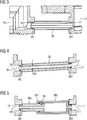
- Fig. 3 shows a longitudinal section of a tube 38 which connects two oil chambers 16, 17 of a WKA transmission together to allow the exchange of oil between the two oil chambers 16, 17 through the tube 38 therethrough.
- Each of the oil chambers 16, 17 has a circular opening 161, 171 which is formed through a bore through the transmission housing.
- the substantially horizontal central axes of the circular openings are ideally aligned, any deviations can be compensated by the fits of the tube in the openings.
- the tube 38 is made of metal, for. Steel.
- the tube can also be made of other suitable materials such as plastic, e.g. Glass fiber reinforced plastic, be made.
- the diameter of the tube 38 is preferably in the range of 50 to 300 mm.
- the wall thickness of the tube 28 is preferably in the range of 10 to 100 mm.
- the two ends of the tube 38 are each inserted into one of the two opposite openings 161, 171.
- the ends of the tube are machined in diameter so that the ends inserted into the openings 161, 171 still have some play. This makes it possible that a possible radial offset of the two oil chambers 16, 17, ie an axial offset .DELTA.A of the two corresponding openings 161, 171, can be compensated by a misalignment of the tube 38, as in Fig. 4 is shown.
- sealing elements 381, 382, here: O-rings are arranged between the inner surfaces of the openings 161, 171 and the outer surfaces of the pipe ends. It is preferred if the sealing elements 381, 382 are placed on the outer surfaces of the pipe ends before inserting the pipe into the openings 161, 171.
- Fig. 5 shows a two-part tube 38 having a first tube part 38a and a second tube part 38b.
- the two tube parts 38a, 38b are inserted with one end into one of the two openings 161, 171.
- the other two ends of the tube parts 38a, 38b the so-called.
- Connecting ends, 38a, 38b are inserted into one another for connection of the two tube parts;
- the outer diameter of the connection end of the first pipe part 38a and the inner diameter of the connection end of the second pipe part 38b are formed so that the connection end of the first pipe part 38a can be inserted into the connection end of the second pipe part 38b.
- the connection has some radial clearance, so that the connection sealing sealing ring 391 between the outer diameter of the narrower tube portion 38a and the inner diameter of the other tube portion 38b can be inserted.
- the two tube parts 38a, 38b are connected to a screw 39 extending radially through both tube parts 38a, 38b, eg a grub screw.
- Axial and radial displacement of the two by the pipe 38 interconnected oil chambers 16, 17 is compensated by axial and radial clearance of the pipe parts 38a, 38b at the ends with which the pipe parts 38a, 38b in the openings 161, 171 of the oil chambers 16th , 17 are inserted.
Landscapes
- Engineering & Computer Science (AREA)
- General Engineering & Computer Science (AREA)
- Mechanical Engineering (AREA)
- Life Sciences & Earth Sciences (AREA)
- Sustainable Development (AREA)
- Sustainable Energy (AREA)
- Chemical & Material Sciences (AREA)
- Combustion & Propulsion (AREA)
- General Details Of Gearings (AREA)
- Wind Motors (AREA)
- Measuring Fluid Pressure (AREA)
Abstract
Description
- Die vorliegende Erfindung betrifft ein Windkraft-Getriebe.
- Windkraft-Getriebe, auch als WKA-Getriebe bezeichnet, übersetzen eine windgetriebene Rotordrehung in eine Drehung eines elektrischen Generators (WKA = Windkraftanlage). Dabei kommen oftmals mehrstufige Getriebe zum Einsatz. Beispielsweise offenbart
EP 2 199 607 B1 (Winergy AG) 23.06.2010 ein WKA-Ge-triebe mit einer ersten und einer zweiten Planetengetriebestufe und einer den Planetengetriebestufen nachgeschalteten Stirnradgetriebestufe. - WKA-Getriebe benötigen während des Betriebs eine ausreichende Ölschmierung. Zur Aufnahme des dazu verwendeten Schmieröls weist ein WKA-Getriebe Ölräume auf, d.h. zumindest teilweise mit Öl gefüllte Hohlräume, welche sich in vertikal unteren Bereichen des Getriebegehäuses befinden, da sich aufgrund der Schwerkraft das Schmieröl von selbst dort sammelt.
Fig. 1 zeigt schematisch eine Seitenansicht eines WKA-Getriebes 1 mit einer ersten Planetengetriebestufe 11, einer zweiten Planetengetriebestufe 12 sowie einer Stirnradgetriebestufe 13, wobei die quer zur Getriebeachse A gemessenen Abmessungen, z.B. der Hohlrad-Durchmesser, der zweiten Planetengetriebestufe 12 erheblich kleiner sind als die Abmessungen der ersten Planetengetriebestufe 11. Die Getriebestufen 11, 12, 13 wandeln sukzessive eine Drehzahl und ein Drehmoment einer Rotorwelle 14 in eine höhere Drehzahl und ein niedrigeres Drehmoment einer Generatorwelle 15. Vertikal unterhalb der ersten Planetengetriebestufe 11 und der Stirnradgetriebestufe 13 weist das Getriebegehäuse jeweils Ölwannen 16, 17 auf, in denen sich das im Betrieb der Getriebestufen zur Schmierung verwendete Öl sammelt. Typische Ölniveaus beim Stillstand des Getriebes sind inFig. 1 gestrichelt N16, N17 angedeutet. Die beiden Ölwannen 16, 17 sind durch eine an der Außenseite des Getriebegehäuses angeordnete drucklose Ölleitung 18 miteinander verbunden. Die Ölleitung 18 muss dabei öldicht und in der Lage sein, Fertigungstoleranzen der Schnittstellen, d.h. der Anschlussstellen der Ölleitung 18 an die Ölwannen 16, 17, auszugleichen. - Bisher werden solche Ölleitungen, die die beiden Ölwannen eines WKA-Getriebes miteinander verbinden, in der Regel entweder als eine Schlauchleitung oder als eine Kombination eines Rohrs mit einem Rohrkompensator ausgebildet.
- Nachteilig bei einer Schlauchleitung ist insbesondere, dass das Schlauchmaterial altert und sich seine Elastizitätseigenschaften verschlechtern, was zu Undichtigkeiten führen kann.
-
Fig. 2 zeigt einen Schnitt eines herkömmlichen WKA-Getriebes, bei dem die Ölleitung ein Rohr 28 und einen Rohrkompensator 29 umfasst, die an ihren axialen Enden jeweils einen Flansch 281, 282 bzw. 291, 292 aufweisen. Die Flansche 281, 282 sind vorzugsweise SAE-Flansche (SAE = Society of Automotive Engineers). Das Rohr 28 und der Kompensator 29 sind über jeweils einen Flansch 281, 292 miteinander verbunden. Über die jeweils anderen Flansche 282, 291 ist die Rohr-Kompensator-Kombination an die Anschlussstellen der Ölwannen 16, 17 angeschlossen. Der Kompensator 29 ist dabei ein flexibles Element zum Ausgleich von Bewegungen der Ölleitung, insbesondere bei thermischen Längenänderungen Vibrationen, Wanddurchführungen oder Setzungserscheinungen. Die Kompensation von Toleranzen erfolgt dabei mechanisch über einen elastischen Balg des Kompensators 29. Nachteilig bei einer Rohr-Kompensator-Kombination sind die Vielzahl der Bauteile und die relativ hohen Investitions-Kosten. - Es ist Aufgabe der vorliegenden Erfindung, ein Windkraft-Getriebe mit einer verbesserten Ölleitung zwischen zwei Ölräumen des Getriebes bereitzustellen.
- Diese Aufgabe wird erfindungsgemäß durch ein Windkraft-Getriebe mit den in Anspruch 1 angegebenen Merkmalen gelöst. Das Windkraft-Getriebe umfasst zwei Ölräume zur Aufnahme von Öl. Jeder der Ölräume weist eine Öffnung zum Durchtritt von Öl auf. Die beiden Ölräume sind durch ein Rohr zur Leitung von Öl miteinander verbunden, welches mit jeweils einem Ende in den Öffnungen angeordnet ist. Die Öffnungen weisen jeweils eine Konizität mit einem inneren Konus, der sich von dem jeweiligen Ölraum weg öffnet, auf. Die in den Öffnungen angeordneten Enden des Rohrs weisen eine entsprechende Konizität mit einem äußeren Konus auf. Zur Abdichtung ist zwischen dem inneren Konus der Öffnungen und dem äußeren Konus der Rohrenden jeweils mindestens ein statisches Dichtungselement angeordnet.
- Die Ölräume sind Ölbehälter, insbesondere in das Getriebegehäuse integrierte Hohlräume zur Aufnahme von Öl, welches zur Schmierung des Getriebes dient. Die Öffnungen der Ölräume führen von den Ölräumen nach außen, d.h. in die Umgebung des Getriebes. Das Verbindungsrohr verläuft also außerhalb des Getriebegehäuses. Die beiden Ölräume können jeweils einer Getriebestufe zugeordnet sein, z.B. der erste Ölraum einer Planetenstufe und der zweite Ölraum einer Stirnradstufe.
- Erfindungsgemäß erfolgt die öldichte Verbindung der beiden Ölräume mittels eines Rohres, das in die beiden Ölräume mittels einer Spielpassung eingesteckt wird. Die axiale Fixierung des Rohres erfolgt beidseitig, d.h. an jedem der beiden Ölräume, durch einen Absatz an den Rohrenden. Ein Ausgleich der Toleranzen der Öffnungen der Ölräume erfolgt durch eine Konizität der Passung. Die Abdichtung der Rohrverbindung gegen ein ungewolltes Austreten von Öl erfolgt mittels einer oder mehrerer statischer Dichtungen, z.B. durch O-Ringe.
- Die erfindungsgemäße Lösung führt, durch eine Reduzierung der verwendeten Bauteile und der Bearbeitungsoperationen, zu einer deutlichen Senkung der Herstellkosten gegenüber den bisher bekannten Lösungen.
- Vorteilhafte Ausgestaltungen und Weiterbildungen der Erfindung sind in den abhängigen Ansprüchen angegeben. Dabei kann das erfindungsgemäße Verfahren auch entsprechend den abhängigen Vorrichtungsansprüchen weitergebildet sein, und umgekehrt.
- Gemäß einer bevorzugten Ausgestaltung der Erfindung weist mindestens eines der Rohrenden eine Fase an seinem Außenumfang auf. Von Vorteil ist dabei, dass das Einführen des Rohrendes in die Öffnung erleichtert wird.
- Gemäß einer bevorzugten Weiterbildung der Erfindung weist mindestens eines der Rohrenden einen Absatz für eine axiale Fixierung des Rohrs an der zugeordneten Öffnung auf. Von Vorteil ist dabei, dass das Rohr nicht weiter als gewollt in die Öffnung hineinrutschen kann, so dass z.B. eine ungewollte Quetschung eines Dichtelements vermieden wird.
- Gemäß einer bevorzugten Weiterbildung der Erfindung umfasst das Rohr mehrere Rohrteile, wobei mindestens zwei Rohrteile axial zueinander verschiebbar sind. Dadurch wird die Montage und Demontage des Rohrs an einem WKA-Getriebe erleichtert. Die Abdichtung der mindestens zwei axial zueinander verschiebbaren Rohrteile kann durch ein Dichtelement, z.B. einen O-Ring, erfolgen. Die axiale Fixierung der mindestens zwei axial zueinander verschiebbaren Rohrteile kann durch eine radial verlaufende Schraubverbindung, z.B. eine Madenschraube, erfolgen.
- Im Folgenden wird die Erfindung anhand mehrerer Ausführungsbeispiele unter Zuhilfenahme der beiliegenden Zeichnung erläutert. Es zeigt jeweils schematisch und nicht maßstabsgetreu
- Fig. 3
- einen Längsschnitt einer ersten Ausgestaltung eines Rohrs zur Leitung von Öl;
- Fig. 4
- einen Längsschnitt einer Radialverlagerung der Ölräume; und
- Fig. 5
- einen Längsschnitt eines zweiteiligen Rohrs zur Leitung von Öl.
-
Fig. 3 zeigt ein Längsschnitt eines Rohrs 38, welches zwei Ölräume 16, 17 eines WKA-Getriebes miteinander verbindet, um den Austausch von Öl zwischen den beiden Ölräumen 16, 17 durch das Rohr 38 hindurch zu ermöglichen. - Jeder der Ölräume 16, 17 weist eine kreisrunde Öffnung 161, 171 auf, die durch eine Bohrung durch das Getriebegehäuse ausgebildet wird. Die im Wesentlichen waagrecht verlaufenden Mittelachsen der Kreisöffnungen fluchten im Idealfall, eventuelle Abweichungen können durch die Passungen des Rohrs in den Öffnungen ausgeglichen werden.
- Das Rohr 38 besteht beispielsweise aus Metall, z. B. Stahl. Das Rohr kann aber auch aus anderen geeigneten Materialien wie Kunststoff, z.B. Glasfaserverstärktem Kunststoff, gefertigt sein. Der Durchmesser des Rohrs 38 liegt vorzugsweise im Bereich von 50 bis 300 mm. Die Wandstärke des Rohres 28 liegt vorzugsweise im Bereich von 10 bis 100 mm.
- Die beiden Enden des Rohrs 38 sind jeweils in eine der beiden gegenüberliegenden Öffnungen 161, 171 eingesetzt. Dazu sind die Enden des Rohrs im Durchmesser so bearbeitet, dass die in die Öffnungen 161, 171 eingesetzten Enden noch ein gewisses Spiel aufweisen. Dadurch ist es möglich, dass ein evtl. Radialversatz der beiden Ölräume 16, 17, d.h. ein Achsversatz ΔA der beiden entsprechenden Öffnungen 161, 171, durch eine Schiefstellung des Rohrs 38 ausgeglichen werden kann, wie in
Fig. 4 gezeigt ist. - Zwischen den Innenflächen der Öffnungen 161, 171 und den Außenflächen der Rohrenden sind Dichtelemente 381, 382, hier: O-Ringe, angeordnet. Es ist bevorzugt, wenn die Dichtelemente 381, 382 vor dem Einschieben des Rohrs in die Öffnungen 161, 171 auf die Außenflächen der Rohrenden aufgesetzt werden.
- Die Montage des einteiligen Rohrs 38 von
Fig. 3 in das WKA-Getriebe erfolgt, in dem das Rohr 38 beim Verbinden der Getriebestufen 11, 12, 13 in die jeweiligen Öffnungen 161, 171 eingesteckt wird. Zum Austausch des Rohrs 38 ist es erforderlich, die Stirnradstufe 13 von der zweiten Planetenstufe 12 zu lösen und axial auseinander zu schieben, damit das Rohr 38 aus den Öffnungen geschoben werden kann. -
Fig. 5 zeigt ein zweiteiliges Rohr 38 mit einem ersten Rohrteil 38a und einem zweiten Rohrteil 38b. Die beiden Rohrteile 38a, 38b sind mit jeweils einem Ende in eine der beiden Öffnungen 161, 171 eingesteckt. Die beiden anderen Enden der Rohrteile 38a, 38b, die sog. Verbindungsenden, sind zur Verbindung der beiden Rohrteile 38a, 38b ineinandergesteckt; dabei sind der Außen-Durchmesser des Verbindungsendes des ersten Rohrteils 38a und der Innen-Durchmesser des Verbindungsendes des zweiten Rohrteils 38b so ausgebildet, dass das Verbindungsende des ersten Rohrteils 38a in das Verbindungsende des zweiten Rohrteils 38b eingesteckt werden kann. Die Verbindung weist dabei etwas radiales Spiel auf, damit ein die Verbindung abdichtender Dichtring 391 zwischen dem Außen-durchmesser des engeren Rohrteils 38a und dem Innendurchmesser des weiteren Rohrteils 38b eingeschoben werden kann. - Zur axialen Sicherung der beiden Rohrteile 38a, 38b relativ zueinander werden die beiden Rohrteile 38a, 38b mit einer radial durch beide Rohrteile 38a, 38b verlaufenden Schraube 39, z.B. einer Madenschraube, verbunden. Axial- und Radial-Versatz der beiden durch das Rohr 38 miteinander verbundenen Ölräume 16, 17 wird über axiales und radiales Spiel der Rohrteile 38a, 38b an den Enden ausgeglichen, mit denen die Rohrteile 38a, 38b in die Öffnungen 161, 171 der Ölräume 16, 17 eingesteckt sind.
- Die Montage des zweiteiligen Rohrs 38a, 38b von
Fig. 5 in das WKA-Getriebe erfolgt, in dem die Rohrteile 38a, 38b zunächst weit ineinander geschoben werden, dann axial auf die Öffnungen 161, 171 ausgerichtet werden und dann die Rohrteile 38a, 38b axial auseinander und gleichzeitig in die jeweiligen Öffnungen 161, 171 eingeschoben werden. Zuletzt wird die axiale Lage der Rohrteile 38a, 38b zueinander durch die Schraubverbindung 39 gesichert. Durch die Möglichkeit der Längenänderung des zweiteiligen Rohrs 38a, 38b ist es zum Austausch des Rohrs 38 somit nicht erforderlich, die Stirnradstufe 13 von der zweiten Planetenstufe 12 zu lösen und axial auseinander zu schieben, sondern das Rohr kann ohne eine Demontage der Getriebestufen 12, 13 gewechselt werden. - Obwohl die Erfindung im Detail durch die bevorzugten Ausführungsbeispiele näher illustriert und beschrieben wurde, so ist die Erfindung nicht durch die offenbarten Beispiele eingeschränkt, und andere Variationen können vom Fachmann hieraus abgeleitet werden, ohne den Schutzumfang der Erfindung zu verlassen.
Claims (4)
- Windkraft-Getriebe (1) mit zwei Ölräumen (16, 17) zur Aufnahme von Öl,
wobei jeder der Ölräume (16, 17) eine Öffnung (161, 171) zum Durchtritt von Öl aufweist,
wobei die beiden Ölräume (16, 17) durch ein Rohr (38, 38a, 38b) zur Leitung von Öl miteinander verbunden sind, welches mit jeweils einem Ende in den Öffnungen (161, 171) angeordnet ist,
wobei die Öffnungen (161, 171) jeweils eine Konizität mit einem inneren Konus, der sich von dem jeweiligen Ölraum (16, 17) weg öffnet, aufweisen, und die in den Öffnungen (161, 171) angeordneten Enden des Rohrs (38, 38a, 38b) eine entsprechende Konizität mit einem äußeren Konus aufweisen,
wobei zur Abdichtung zwischen dem inneren Konus der Öffnungen (161, 171) und dem äußeren Konus der Rohrenden jeweils mindestens ein statisches Dichtungselement (381, 182) angeordnet ist. - Windkraft-Getriebe nach Anspruch 1,
wobei mindestens eines der Rohrenden eine Fase aufweist. - Windkraft-Getriebe nach Anspruch 1 oder 2,
wobei mindestens eines der Rohrenden einen Absatz für eine axiale Fixierung des Rohrs (38, 38a, 38b) an der zugeordneten Öffnung (161, 171) aufweist. - Windkraft-Getriebe nach einem der vorhergehenden Ansprüche,
wobei das Rohr (38, 38a, 38b) mehrere Rohrteile (38a, 38b) umfasst, wobei mindestens zwei Rohrteile (38a, 38b) axial zueinander verschiebbar sind.
Priority Applications (4)
| Application Number | Priority Date | Filing Date | Title |
|---|---|---|---|
| ES14186836.4T ES2629403T3 (es) | 2014-09-29 | 2014-09-29 | Mecanismo transmisor de aerogenerador |
| EP14186836.4A EP3001070B1 (de) | 2014-09-29 | 2014-09-29 | Windkraft-Getriebe |
| US14/867,841 US20160090967A1 (en) | 2014-09-29 | 2015-09-28 | Wind power gearbox |
| CN201510629624.4A CN105464909B (zh) | 2014-09-29 | 2015-09-28 | 风力传动装置 |
Applications Claiming Priority (1)
| Application Number | Priority Date | Filing Date | Title |
|---|---|---|---|
| EP14186836.4A EP3001070B1 (de) | 2014-09-29 | 2014-09-29 | Windkraft-Getriebe |
Publications (2)
| Publication Number | Publication Date |
|---|---|
| EP3001070A1 true EP3001070A1 (de) | 2016-03-30 |
| EP3001070B1 EP3001070B1 (de) | 2017-03-22 |
Family
ID=51619097
Family Applications (1)
| Application Number | Title | Priority Date | Filing Date |
|---|---|---|---|
| EP14186836.4A Not-in-force EP3001070B1 (de) | 2014-09-29 | 2014-09-29 | Windkraft-Getriebe |
Country Status (4)
| Country | Link |
|---|---|
| US (1) | US20160090967A1 (de) |
| EP (1) | EP3001070B1 (de) |
| CN (1) | CN105464909B (de) |
| ES (1) | ES2629403T3 (de) |
Cited By (4)
| Publication number | Priority date | Publication date | Assignee | Title |
|---|---|---|---|---|
| WO2017144225A1 (de) * | 2016-02-23 | 2017-08-31 | Zf Friedrichshafen Ag | Teilbares pitchrohr |
| DE102017222663A1 (de) | 2017-12-13 | 2019-06-13 | Magna powertrain gmbh & co kg | Getriebe und Verfahren zur Montage eines solchen Getriebes |
| DE102018220534A1 (de) * | 2018-11-29 | 2020-06-04 | Zf Friedrichshafen Ag | Öldrainage |
| CN117662387A (zh) * | 2022-08-30 | 2024-03-08 | 北京金风科创风电设备有限公司 | 风力发电机组 |
Citations (3)
| Publication number | Priority date | Publication date | Assignee | Title |
|---|---|---|---|---|
| US20100007151A1 (en) * | 2008-07-10 | 2010-01-14 | General Electric Company | Internal lubrication for a gearbox, a power-generating wind turbine system, and a power-generating system |
| EP2199607A2 (de) | 2008-12-19 | 2010-06-23 | Winergy AG | Planetengetriebe für eine Windkraftanlage |
| EP2541096A1 (de) * | 2011-06-30 | 2013-01-02 | Siemens Aktiengesellschaft | Antriebssystem für eine Windkraftanlage |
Family Cites Families (16)
| Publication number | Priority date | Publication date | Assignee | Title |
|---|---|---|---|---|
| US2818232A (en) * | 1952-07-28 | 1957-12-31 | Dean W Osmun | Jarring tools |
| US3001804A (en) * | 1957-03-18 | 1961-09-26 | Rolls Royce | Pipe end fittings |
| US4209193A (en) * | 1977-05-17 | 1980-06-24 | Vetco, Inc. | Rigid connector for large diameter pipe |
| US4706997A (en) * | 1982-05-19 | 1987-11-17 | Carstensen Kenneth J | Coupling for tubing or casing and method of assembly |
| GB8414203D0 (en) * | 1984-06-04 | 1984-07-11 | Hunting Oilfield Services Ltd | Pipe connectors |
| US4659116A (en) * | 1985-04-29 | 1987-04-21 | Dowell Schlumberger Incorporated | Pipe union for cryogenic fluids |
| JPH0240385Y2 (de) * | 1986-02-14 | 1990-10-29 | ||
| DE3709819A1 (de) * | 1986-05-12 | 1987-11-19 | Waluga Armaturen | Rohrverschraubung |
| DE69804365T2 (de) * | 1997-04-08 | 2002-12-12 | Waterworks Technology Development Organization Co., Ltd. | Teleskopische und schwenkbare Rohrverbindung |
| NO310372B1 (no) * | 1999-08-02 | 2001-06-25 | Bakke Technology As | Delt koplingsanordning med gjennomgående boring |
| US7591486B2 (en) * | 2005-07-01 | 2009-09-22 | Chrysler Group Llc | Fluid connector |
| CN101670779A (zh) * | 2009-10-14 | 2010-03-17 | 奇瑞汽车股份有限公司 | 一种具有双油箱的汽车 |
| CN101975256B (zh) * | 2010-11-17 | 2012-06-13 | 合肥工业大学科教开发部 | 一种8at齿轮传动系统 |
| FR2978231B1 (fr) * | 2011-07-20 | 2013-08-02 | Airbus Operations Sas | Dispositif de raccord anti-flambage pour tuyauteries |
| US8764066B1 (en) * | 2012-09-21 | 2014-07-01 | Tyler S. Rice | Expansion coupling system |
| DE102013001389B4 (de) * | 2013-01-25 | 2015-10-29 | A. Kayser Automotive Systems Gmbh | Kurbelgehäuseentlüftung für eine Brennkraftmaschine, Tankentlüftungsleitung und Verbindungssytem hierfür |
-
2014
- 2014-09-29 ES ES14186836.4T patent/ES2629403T3/es active Active
- 2014-09-29 EP EP14186836.4A patent/EP3001070B1/de not_active Not-in-force
-
2015
- 2015-09-28 CN CN201510629624.4A patent/CN105464909B/zh not_active Expired - Fee Related
- 2015-09-28 US US14/867,841 patent/US20160090967A1/en not_active Abandoned
Patent Citations (3)
| Publication number | Priority date | Publication date | Assignee | Title |
|---|---|---|---|---|
| US20100007151A1 (en) * | 2008-07-10 | 2010-01-14 | General Electric Company | Internal lubrication for a gearbox, a power-generating wind turbine system, and a power-generating system |
| EP2199607A2 (de) | 2008-12-19 | 2010-06-23 | Winergy AG | Planetengetriebe für eine Windkraftanlage |
| EP2541096A1 (de) * | 2011-06-30 | 2013-01-02 | Siemens Aktiengesellschaft | Antriebssystem für eine Windkraftanlage |
Cited By (10)
| Publication number | Priority date | Publication date | Assignee | Title |
|---|---|---|---|---|
| WO2017144225A1 (de) * | 2016-02-23 | 2017-08-31 | Zf Friedrichshafen Ag | Teilbares pitchrohr |
| US10935004B2 (en) | 2016-02-23 | 2021-03-02 | Zf Friedrichshafen Ag | Splittable pitch tube |
| DE102017222663A1 (de) | 2017-12-13 | 2019-06-13 | Magna powertrain gmbh & co kg | Getriebe und Verfahren zur Montage eines solchen Getriebes |
| WO2019115106A1 (de) | 2017-12-13 | 2019-06-20 | Magna powertrain gmbh & co kg | Getriebe und verfahren zur montage eines solchen getriebes |
| DE102017222663B4 (de) | 2017-12-13 | 2022-07-14 | Magna powertrain gmbh & co kg | Getriebe und Verfahren zur Montage eines solchen Getriebes |
| US11428308B2 (en) | 2017-12-13 | 2022-08-30 | Magna powertrain gmbh & co kg | Transmission and method for assembling a transmission of this type |
| DE102018220534A1 (de) * | 2018-11-29 | 2020-06-04 | Zf Friedrichshafen Ag | Öldrainage |
| US11754168B2 (en) | 2018-11-29 | 2023-09-12 | Zf Friedrichshafen Ag | Oil drainage |
| EP3887693B1 (de) * | 2018-11-29 | 2026-04-29 | ZF Friedrichshafen AG | Öldrainage |
| CN117662387A (zh) * | 2022-08-30 | 2024-03-08 | 北京金风科创风电设备有限公司 | 风力发电机组 |
Also Published As
| Publication number | Publication date |
|---|---|
| ES2629403T3 (es) | 2017-08-09 |
| US20160090967A1 (en) | 2016-03-31 |
| EP3001070B1 (de) | 2017-03-22 |
| CN105464909A (zh) | 2016-04-06 |
| CN105464909B (zh) | 2018-07-06 |
Similar Documents
| Publication | Publication Date | Title |
|---|---|---|
| DE102013103107B4 (de) | Getriebe für eine elektrisch antreibbare Achse eines Kraftfahrzeugs | |
| EP3001070B1 (de) | Windkraft-Getriebe | |
| EP3029359A1 (de) | Vorrichtung mit einem drehfesten ersten bauteil und einem zumindest bereichsweise mit dem ersten bauteil drehbar verbundenen zweiten bauteil | |
| EP3029357A1 (de) | Vorrichtung mit einem drehfesten ersten bauteil und einem zumindest bereichsweise mit dem ersten bauteil drehbar verbundenen zweiten bauteil | |
| DE10312941A1 (de) | Bausatz für eine Baureihe von Getriebemotoren | |
| WO2017032558A1 (de) | Generatorgetriebe einer windenergieanlage | |
| WO2016119802A1 (de) | Dichtungsanordnung für ein getriebe, insbesondere für die abtriebswelle eines getriebes, und getriebe mit dichtungsanordnung | |
| DE102017121348B4 (de) | Kupplungseinrichtung, Hybridmodul und Antriebsstrang | |
| EP3327316A1 (de) | Vorrichtung mit einem drehfesten ersten bauteil und einem zumindest bereichsweise mit dem ersten bauteil drehbar verbundenen zweiten bauteil | |
| DE102015223669B4 (de) | Planetengetriebe für eine Windkraftanlage und Verfahren zur Montage des Planetengetriebes | |
| EP3295060B1 (de) | Getriebe mit einer in einem flanschteil mittels eines lagers gelagerten eintreibenden welle | |
| EP3795825A1 (de) | Elektrisch isoliertes durchführungsrohr | |
| DE102005020415A1 (de) | Antriebseinheit für ein Kraftfahrzeug | |
| WO2007062814A1 (de) | Dictungsvorrichtung für ein doppelkupplungsgetriebe eines kraftfahrzeuges | |
| EP1319871A2 (de) | Schmiermittelzuführung für ein Planetengetriebe | |
| DE102005052451A1 (de) | Einrichtung zur Steuerung des Volumenstroms in innenbeölten Wellen | |
| DE102013007462A1 (de) | Kugel-Schneckenradtrieb | |
| EP3258133A1 (de) | Planetengetriebemodul | |
| EP4305326B1 (de) | Übertragungsvorrichtung mit einer schwimmenden buchse für versorgungsmittel zwischen bauteilen eines planetengetriebes | |
| DE102015201146A1 (de) | Harmonisches Getriebe | |
| DE102018122335A1 (de) | Automatgetriebe mit Retarder | |
| DE102017206598A1 (de) | Getriebegehäuse mit integrierten Ölkanälen | |
| DE102005052456A1 (de) | Einrichtung zur Steuerung des Volumenstroms in innenbeölten Wellen | |
| EP3887693B1 (de) | Öldrainage | |
| EP3513098B1 (de) | Hydrodynamisches getriebe für schienenfahrzeuge |
Legal Events
| Date | Code | Title | Description |
|---|---|---|---|
| PUAI | Public reference made under article 153(3) epc to a published international application that has entered the european phase |
Free format text: ORIGINAL CODE: 0009012 |
|
| AK | Designated contracting states |
Kind code of ref document: A1 Designated state(s): AL AT BE BG CH CY CZ DE DK EE ES FI FR GB GR HR HU IE IS IT LI LT LU LV MC MK MT NL NO PL PT RO RS SE SI SK SM TR |
|
| AX | Request for extension of the european patent |
Extension state: BA ME |
|
| 17P | Request for examination filed |
Effective date: 20160421 |
|
| RBV | Designated contracting states (corrected) |
Designated state(s): AL AT BE BG CH CY CZ DE DK EE ES FI FR GB GR HR HU IE IS IT LI LT LU LV MC MK MT NL NO PL PT RO RS SE SI SK SM TR |
|
| GRAP | Despatch of communication of intention to grant a patent |
Free format text: ORIGINAL CODE: EPIDOSNIGR1 |
|
| RIC1 | Information provided on ipc code assigned before grant |
Ipc: F16H 57/033 20120101ALI20160921BHEP Ipc: F16H 57/04 20060101AFI20160921BHEP |
|
| INTG | Intention to grant announced |
Effective date: 20161011 |
|
| STAA | Information on the status of an ep patent application or granted ep patent |
Free format text: STATUS: GRANT OF PATENT IS INTENDED |
|
| GRAS | Grant fee paid |
Free format text: ORIGINAL CODE: EPIDOSNIGR3 |
|
| GRAA | (expected) grant |
Free format text: ORIGINAL CODE: 0009210 |
|
| STAA | Information on the status of an ep patent application or granted ep patent |
Free format text: STATUS: THE PATENT HAS BEEN GRANTED |
|
| AK | Designated contracting states |
Kind code of ref document: B1 Designated state(s): AL AT BE BG CH CY CZ DE DK EE ES FI FR GB GR HR HU IE IS IT LI LT LU LV MC MK MT NL NO PL PT RO RS SE SI SK SM TR |
|
| REG | Reference to a national code |
Ref country code: GB Ref legal event code: FG4D Free format text: NOT ENGLISH |
|
| REG | Reference to a national code |
Ref country code: CH Ref legal event code: EP |
|
| REG | Reference to a national code |
Ref country code: AT Ref legal event code: REF Ref document number: 878120 Country of ref document: AT Kind code of ref document: T Effective date: 20170415 |
|
| REG | Reference to a national code |
Ref country code: IE Ref legal event code: FG4D Free format text: LANGUAGE OF EP DOCUMENT: GERMAN |
|
| REG | Reference to a national code |
Ref country code: DE Ref legal event code: R096 Ref document number: 502014003087 Country of ref document: DE |
|
| REG | Reference to a national code |
Ref country code: NL Ref legal event code: MP Effective date: 20170322 |
|
| PG25 | Lapsed in a contracting state [announced via postgrant information from national office to epo] |
Ref country code: NO Free format text: LAPSE BECAUSE OF FAILURE TO SUBMIT A TRANSLATION OF THE DESCRIPTION OR TO PAY THE FEE WITHIN THE PRESCRIBED TIME-LIMIT Effective date: 20170622 Ref country code: GR Free format text: LAPSE BECAUSE OF FAILURE TO SUBMIT A TRANSLATION OF THE DESCRIPTION OR TO PAY THE FEE WITHIN THE PRESCRIBED TIME-LIMIT Effective date: 20170623 Ref country code: LT Free format text: LAPSE BECAUSE OF FAILURE TO SUBMIT A TRANSLATION OF THE DESCRIPTION OR TO PAY THE FEE WITHIN THE PRESCRIBED TIME-LIMIT Effective date: 20170322 Ref country code: HR Free format text: LAPSE BECAUSE OF FAILURE TO SUBMIT A TRANSLATION OF THE DESCRIPTION OR TO PAY THE FEE WITHIN THE PRESCRIBED TIME-LIMIT Effective date: 20170322 |
|
| REG | Reference to a national code |
Ref country code: ES Ref legal event code: FG2A Ref document number: 2629403 Country of ref document: ES Kind code of ref document: T3 Effective date: 20170809 |
|
| REG | Reference to a national code |
Ref country code: LT Ref legal event code: MG4D |
|
| RAP2 | Party data changed (patent owner data changed or rights of a patent transferred) |
Owner name: SIEMENS AKTIENGESELLSCHAFT |
|
| PG25 | Lapsed in a contracting state [announced via postgrant information from national office to epo] |
Ref country code: LV Free format text: LAPSE BECAUSE OF FAILURE TO SUBMIT A TRANSLATION OF THE DESCRIPTION OR TO PAY THE FEE WITHIN THE PRESCRIBED TIME-LIMIT Effective date: 20170322 Ref country code: SE Free format text: LAPSE BECAUSE OF FAILURE TO SUBMIT A TRANSLATION OF THE DESCRIPTION OR TO PAY THE FEE WITHIN THE PRESCRIBED TIME-LIMIT Effective date: 20170322 Ref country code: BG Free format text: LAPSE BECAUSE OF FAILURE TO SUBMIT A TRANSLATION OF THE DESCRIPTION OR TO PAY THE FEE WITHIN THE PRESCRIBED TIME-LIMIT Effective date: 20170622 Ref country code: RS Free format text: LAPSE BECAUSE OF FAILURE TO SUBMIT A TRANSLATION OF THE DESCRIPTION OR TO PAY THE FEE WITHIN THE PRESCRIBED TIME-LIMIT Effective date: 20170322 |
|
| REG | Reference to a national code |
Ref country code: FR Ref legal event code: PLFP Year of fee payment: 4 |
|
| PG25 | Lapsed in a contracting state [announced via postgrant information from national office to epo] |
Ref country code: NL Free format text: LAPSE BECAUSE OF FAILURE TO SUBMIT A TRANSLATION OF THE DESCRIPTION OR TO PAY THE FEE WITHIN THE PRESCRIBED TIME-LIMIT Effective date: 20170322 |
|
| REG | Reference to a national code |
Ref country code: CH Ref legal event code: NV Representative=s name: SIEMENS SCHWEIZ AG, CH Ref country code: CH Ref legal event code: PCOW Free format text: NEW ADDRESS: WERNER-VON-SIEMENS-STRASSE 1, 80333 MUENCHEN (DE) |
|
| PG25 | Lapsed in a contracting state [announced via postgrant information from national office to epo] |
Ref country code: CZ Free format text: LAPSE BECAUSE OF FAILURE TO SUBMIT A TRANSLATION OF THE DESCRIPTION OR TO PAY THE FEE WITHIN THE PRESCRIBED TIME-LIMIT Effective date: 20170322 Ref country code: RO Free format text: LAPSE BECAUSE OF FAILURE TO SUBMIT A TRANSLATION OF THE DESCRIPTION OR TO PAY THE FEE WITHIN THE PRESCRIBED TIME-LIMIT Effective date: 20170322 Ref country code: SK Free format text: LAPSE BECAUSE OF FAILURE TO SUBMIT A TRANSLATION OF THE DESCRIPTION OR TO PAY THE FEE WITHIN THE PRESCRIBED TIME-LIMIT Effective date: 20170322 Ref country code: EE Free format text: LAPSE BECAUSE OF FAILURE TO SUBMIT A TRANSLATION OF THE DESCRIPTION OR TO PAY THE FEE WITHIN THE PRESCRIBED TIME-LIMIT Effective date: 20170322 Ref country code: IT Free format text: LAPSE BECAUSE OF FAILURE TO SUBMIT A TRANSLATION OF THE DESCRIPTION OR TO PAY THE FEE WITHIN THE PRESCRIBED TIME-LIMIT Effective date: 20170322 |
|
| REG | Reference to a national code |
Ref country code: DE Ref legal event code: R081 Ref document number: 502014003087 Country of ref document: DE Owner name: FLENDER GMBH, DE Free format text: FORMER OWNER: SIEMENS AKTIENGESELLSCHAFT, 80333 MUENCHEN, DE |
|
| PG25 | Lapsed in a contracting state [announced via postgrant information from national office to epo] |
Ref country code: PL Free format text: LAPSE BECAUSE OF FAILURE TO SUBMIT A TRANSLATION OF THE DESCRIPTION OR TO PAY THE FEE WITHIN THE PRESCRIBED TIME-LIMIT Effective date: 20170322 Ref country code: SM Free format text: LAPSE BECAUSE OF FAILURE TO SUBMIT A TRANSLATION OF THE DESCRIPTION OR TO PAY THE FEE WITHIN THE PRESCRIBED TIME-LIMIT Effective date: 20170322 Ref country code: PT Free format text: LAPSE BECAUSE OF FAILURE TO SUBMIT A TRANSLATION OF THE DESCRIPTION OR TO PAY THE FEE WITHIN THE PRESCRIBED TIME-LIMIT Effective date: 20170724 Ref country code: IS Free format text: LAPSE BECAUSE OF FAILURE TO SUBMIT A TRANSLATION OF THE DESCRIPTION OR TO PAY THE FEE WITHIN THE PRESCRIBED TIME-LIMIT Effective date: 20170722 |
|
| REG | Reference to a national code |
Ref country code: ES Ref legal event code: PC2A Owner name: FLENDER GMBH Effective date: 20171219 |
|
| REG | Reference to a national code |
Ref country code: DE Ref legal event code: R097 Ref document number: 502014003087 Country of ref document: DE |
|
| RAP2 | Party data changed (patent owner data changed or rights of a patent transferred) |
Owner name: FLENDER GMBH |
|
| REG | Reference to a national code |
Ref country code: GB Ref legal event code: 732E Free format text: REGISTERED BETWEEN 20171207 AND 20171213 |
|
| PLBE | No opposition filed within time limit |
Free format text: ORIGINAL CODE: 0009261 |
|
| STAA | Information on the status of an ep patent application or granted ep patent |
Free format text: STATUS: NO OPPOSITION FILED WITHIN TIME LIMIT |
|
| PG25 | Lapsed in a contracting state [announced via postgrant information from national office to epo] |
Ref country code: DK Free format text: LAPSE BECAUSE OF FAILURE TO SUBMIT A TRANSLATION OF THE DESCRIPTION OR TO PAY THE FEE WITHIN THE PRESCRIBED TIME-LIMIT Effective date: 20170322 |
|
| 26N | No opposition filed |
Effective date: 20180102 |
|
| PG25 | Lapsed in a contracting state [announced via postgrant information from national office to epo] |
Ref country code: SI Free format text: LAPSE BECAUSE OF FAILURE TO SUBMIT A TRANSLATION OF THE DESCRIPTION OR TO PAY THE FEE WITHIN THE PRESCRIBED TIME-LIMIT Effective date: 20170322 |
|
| REG | Reference to a national code |
Ref country code: FR Ref legal event code: TP Owner name: FLENDER GMBH, DE Effective date: 20180316 |
|
| REG | Reference to a national code |
Ref country code: CH Ref legal event code: PL |
|
| PG25 | Lapsed in a contracting state [announced via postgrant information from national office to epo] |
Ref country code: MC Free format text: LAPSE BECAUSE OF FAILURE TO SUBMIT A TRANSLATION OF THE DESCRIPTION OR TO PAY THE FEE WITHIN THE PRESCRIBED TIME-LIMIT Effective date: 20170322 |
|
| REG | Reference to a national code |
Ref country code: IE Ref legal event code: MM4A |
|
| REG | Reference to a national code |
Ref country code: BE Ref legal event code: MM Effective date: 20170930 |
|
| PG25 | Lapsed in a contracting state [announced via postgrant information from national office to epo] |
Ref country code: LU Free format text: LAPSE BECAUSE OF NON-PAYMENT OF DUE FEES Effective date: 20170929 |
|
| PG25 | Lapsed in a contracting state [announced via postgrant information from national office to epo] |
Ref country code: CH Free format text: LAPSE BECAUSE OF NON-PAYMENT OF DUE FEES Effective date: 20170930 Ref country code: IE Free format text: LAPSE BECAUSE OF NON-PAYMENT OF DUE FEES Effective date: 20170929 Ref country code: LI Free format text: LAPSE BECAUSE OF NON-PAYMENT OF DUE FEES Effective date: 20170930 |
|
| PG25 | Lapsed in a contracting state [announced via postgrant information from national office to epo] |
Ref country code: BE Free format text: LAPSE BECAUSE OF NON-PAYMENT OF DUE FEES Effective date: 20170930 |
|
| REG | Reference to a national code |
Ref country code: FR Ref legal event code: PLFP Year of fee payment: 5 |
|
| PG25 | Lapsed in a contracting state [announced via postgrant information from national office to epo] |
Ref country code: MT Free format text: LAPSE BECAUSE OF FAILURE TO SUBMIT A TRANSLATION OF THE DESCRIPTION OR TO PAY THE FEE WITHIN THE PRESCRIBED TIME-LIMIT Effective date: 20170322 |
|
| PGFP | Annual fee paid to national office [announced via postgrant information from national office to epo] |
Ref country code: FR Payment date: 20180924 Year of fee payment: 5 |
|
| PGFP | Annual fee paid to national office [announced via postgrant information from national office to epo] |
Ref country code: GB Payment date: 20180911 Year of fee payment: 5 Ref country code: FI Payment date: 20180920 Year of fee payment: 5 |
|
| PGFP | Annual fee paid to national office [announced via postgrant information from national office to epo] |
Ref country code: DE Payment date: 20181119 Year of fee payment: 5 |
|
| PGFP | Annual fee paid to national office [announced via postgrant information from national office to epo] |
Ref country code: ES Payment date: 20181217 Year of fee payment: 5 |
|
| PG25 | Lapsed in a contracting state [announced via postgrant information from national office to epo] |
Ref country code: HU Free format text: LAPSE BECAUSE OF FAILURE TO SUBMIT A TRANSLATION OF THE DESCRIPTION OR TO PAY THE FEE WITHIN THE PRESCRIBED TIME-LIMIT; INVALID AB INITIO Effective date: 20140929 |
|
| PG25 | Lapsed in a contracting state [announced via postgrant information from national office to epo] |
Ref country code: CY Free format text: LAPSE BECAUSE OF FAILURE TO SUBMIT A TRANSLATION OF THE DESCRIPTION OR TO PAY THE FEE WITHIN THE PRESCRIBED TIME-LIMIT Effective date: 20170322 |
|
| PG25 | Lapsed in a contracting state [announced via postgrant information from national office to epo] |
Ref country code: MK Free format text: LAPSE BECAUSE OF FAILURE TO SUBMIT A TRANSLATION OF THE DESCRIPTION OR TO PAY THE FEE WITHIN THE PRESCRIBED TIME-LIMIT Effective date: 20170322 |
|
| PG25 | Lapsed in a contracting state [announced via postgrant information from national office to epo] |
Ref country code: TR Free format text: LAPSE BECAUSE OF FAILURE TO SUBMIT A TRANSLATION OF THE DESCRIPTION OR TO PAY THE FEE WITHIN THE PRESCRIBED TIME-LIMIT Effective date: 20170322 |
|
| REG | Reference to a national code |
Ref country code: DE Ref legal event code: R119 Ref document number: 502014003087 Country of ref document: DE |
|
| REG | Reference to a national code |
Ref country code: FI Ref legal event code: MAE |
|
| PG25 | Lapsed in a contracting state [announced via postgrant information from national office to epo] |
Ref country code: FI Free format text: LAPSE BECAUSE OF NON-PAYMENT OF DUE FEES Effective date: 20190929 |
|
| PG25 | Lapsed in a contracting state [announced via postgrant information from national office to epo] |
Ref country code: AL Free format text: LAPSE BECAUSE OF FAILURE TO SUBMIT A TRANSLATION OF THE DESCRIPTION OR TO PAY THE FEE WITHIN THE PRESCRIBED TIME-LIMIT Effective date: 20170322 Ref country code: DE Free format text: LAPSE BECAUSE OF NON-PAYMENT OF DUE FEES Effective date: 20200401 |
|
| GBPC | Gb: european patent ceased through non-payment of renewal fee |
Effective date: 20190929 |
|
| PG25 | Lapsed in a contracting state [announced via postgrant information from national office to epo] |
Ref country code: FR Free format text: LAPSE BECAUSE OF NON-PAYMENT OF DUE FEES Effective date: 20190930 Ref country code: GB Free format text: LAPSE BECAUSE OF NON-PAYMENT OF DUE FEES Effective date: 20190929 |
|
| REG | Reference to a national code |
Ref country code: AT Ref legal event code: MM01 Ref document number: 878120 Country of ref document: AT Kind code of ref document: T Effective date: 20190929 |
|
| REG | Reference to a national code |
Ref country code: ES Ref legal event code: FD2A Effective date: 20210128 |
|
| PG25 | Lapsed in a contracting state [announced via postgrant information from national office to epo] |
Ref country code: AT Free format text: LAPSE BECAUSE OF NON-PAYMENT OF DUE FEES Effective date: 20190929 |
|
| PG25 | Lapsed in a contracting state [announced via postgrant information from national office to epo] |
Ref country code: ES Free format text: LAPSE BECAUSE OF NON-PAYMENT OF DUE FEES Effective date: 20190930 |