EP3000950B1 - Wall console for an awning with adjustable angle control - Google Patents
Wall console for an awning with adjustable angle control Download PDFInfo
- Publication number
- EP3000950B1 EP3000950B1 EP15177190.4A EP15177190A EP3000950B1 EP 3000950 B1 EP3000950 B1 EP 3000950B1 EP 15177190 A EP15177190 A EP 15177190A EP 3000950 B1 EP3000950 B1 EP 3000950B1
- Authority
- EP
- European Patent Office
- Prior art keywords
- awning
- wall
- mounting bracket
- wall console
- retaining
- Prior art date
- Legal status (The legal status is an assumption and is not a legal conclusion. Google has not performed a legal analysis and makes no representation as to the accuracy of the status listed.)
- Not-in-force
Links
- 238000005452 bending Methods 0.000 claims description 9
- 230000008878 coupling Effects 0.000 claims description 9
- 238000010168 coupling process Methods 0.000 claims description 9
- 238000005859 coupling reaction Methods 0.000 claims description 9
- 229910000838 Al alloy Inorganic materials 0.000 claims description 3
- 238000001125 extrusion Methods 0.000 claims 2
- 238000010009 beating Methods 0.000 description 5
- 238000010276 construction Methods 0.000 description 4
- 239000004744 fabric Substances 0.000 description 3
- XLYOFNOQVPJJNP-UHFFFAOYSA-N water Substances O XLYOFNOQVPJJNP-UHFFFAOYSA-N 0.000 description 2
- 230000009471 action Effects 0.000 description 1
- 230000015572 biosynthetic process Effects 0.000 description 1
- 230000008859 change Effects 0.000 description 1
- 230000007423 decrease Effects 0.000 description 1
- 230000001419 dependent effect Effects 0.000 description 1
- 230000000994 depressogenic effect Effects 0.000 description 1
- 238000009434 installation Methods 0.000 description 1
- 230000007246 mechanism Effects 0.000 description 1
Images


Classifications
-
- E—FIXED CONSTRUCTIONS
- E04—BUILDING
- E04F—FINISHING WORK ON BUILDINGS, e.g. STAIRS, FLOORS
- E04F10/00—Sunshades, e.g. Florentine blinds or jalousies; Outside screens; Awnings or baldachins
- E04F10/02—Sunshades, e.g. Florentine blinds or jalousies; Outside screens; Awnings or baldachins of flexible canopy materials, e.g. canvas ; Baldachins
- E04F10/06—Sunshades, e.g. Florentine blinds or jalousies; Outside screens; Awnings or baldachins of flexible canopy materials, e.g. canvas ; Baldachins comprising a roller-blind with means for holding the end away from a building
- E04F10/0637—Sunshades, e.g. Florentine blinds or jalousies; Outside screens; Awnings or baldachins of flexible canopy materials, e.g. canvas ; Baldachins comprising a roller-blind with means for holding the end away from a building with mechanisms for adjusting the inclination of the blind
Definitions
- the invention relates to a wall bracket for an awning with tilt adjustment.
- An example of a wall console with a pitch adjustment for the awning is from the EP 0 821 118 B1 removable.
- a round cross-section support tube which is provided with a groove extending parallel to the longitudinal axis.
- the support tube is clamped in a round recording of the wall bracket, with an adjustable mounted on the wall bracket nut engages in the groove of the support tube.
- U1 From the DE 77 25 749 U1 is a tilting joint for awnings, which is formed by a horizontal pivot axis extending between two seated on the square support tube of the awning supporting plates, and a rotatably mounted thereto holder for the articulated arms 20 of the awning.
- This construction is also relatively expensive.
- the direction of failure of the dropout profile is varied with the awning fabric, but not the inclination position of the support structure of the awning, so essentially the support tube and the fabric shaft held with the cloth bales, and possibly still existing Covers or housing elements.
- These awning parts can not be adapted in their inclination to special installation requirements or circumstances, for example, if the awning to be attached to a sloping rafters.
- a wall bracket with the features in the preamble of claim 1 is characterized by DE10014144U1 known.
- the invention has for its object to provide a wall bracket for an awning with tilt adjustment, the construction of which compared to the prior art is significantly less expensive, while robust and offers easy to perform tilt adjustment.
- the wall construction according to the invention thus only has a body articulated in the assembly and holding limbs and the connecting web, wherein the tilt adjustment can be carried out by a controlled deformation of the connecting web between the assembly and holding limbs. No special tools are necessary for this.
- the flexural rigidity of the connecting web is according to known structural design criteria to the weight to design the awning, its dimensions and the required design reserves with regard to wind and water loads on the awning.
- the wall bracket can consist of a preferably extruded from an aluminum alloy profile part.
- the wall bracket according to the invention is thus particularly suitable for a rational and cost-effective mass production.
- the bending angle of the retaining leg relative to the mounting leg can be fixed at least in a pivoting direction by a stop screw.
- the stop screw is preferably inserted in a corresponding threaded hole at the free end of the retaining leg and is located with its head-facing front end in stop position on the mounting leg. The defined by the stop position limit inclination angle is thus adjustable by a simple screw actuation of the stop screw.
- the front end of the stop screw can be pivotally and rotatably coupled to the mounting leg in a development. This makes it possible to secure the retaining leg of the wall bracket and thus the awning even in the set inclination against both a beating as well as against depression.
- This pivotal and rotational coupling of the front end of the stop screw with the mounting leg can preferably be realized in that the front end of the stop screw has a coupling pin which engages via a passage opening in the mounting position in a recess in the rear wall of the mounting leg.
- the coupling pin is then secured with a securing element under rotation and pivoting play in this recess, so that despite the loose fixation of the stop screw in this recess a rotation and inclination change of the screw and thus a tilt adjustment of the retaining leg is made possible by the pivot axis formed by the bendable connecting web ,
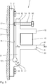
- the wall bracket 1 shown has a substantially plate-shaped mounting leg 2, which has a flat back 3 and on its front side 4 a ramp-shaped in cross-section Stem 5 has.
- the mounting leg 2 is to be attached by means of fastening screws 6, for example, on a building wall 7.
- the wall bracket has a relation to the mounting leg 2 about a horizontal pivot axis S pivotable support leg 8, which is also plate-shaped and facing away from the mounting leg 2 outside with an upwardly open receptacle 9 for a support tube 10 of an awning not shown here ,
- the cross-sectional shape of the receptacle 9, as in Fig. 1 and 2 can be seen, is adapted to the square profile of the support tube 10.
- the horizontal pivot axis S between mounting leg 2 and retaining leg 8 is formed by a bendable connecting web 11 which is integrally formed with these two legs 2, 8.
- the wall thickness of the connecting web 11 is reduced relative to the retaining leg 8 by an inner, in the side view like a loop-like recess 12.
- the bending stiffness of the connecting web to the particular circumstances, such as the weight, the failure length and width of the awning can be adjusted.
- a stop screw 15 is inserted from the side facing away from the building wall 7 side, which abuts with its head 16 facing away from the front end 17 on the mounting leg 2 optionally in the region of the front side 18 of the stem 5 in a threaded hole indicated by dashed lines 14.
- Fig. 2 is the counterclockwise based on Fig. 1 pivoted position of the retaining leg 8 shown, wherein the pivoting is made possible by bending the connecting web 11 of the mounting bracket.
- the pivoting movement towards a bending angle B can be achieved by acting on the retaining leg 8 in the pivoting direction R (FIG. Fig. 1 ) yourself.
- the stop screw 15 can be further screwed into the threaded hole 14 until its front end 17 abuts the mounting leg 2 again.
- the inclination angle N2 of the awning with respect to the horizontal H is opposite to the position in Fig. 1 with a tilt angle N1 significantly reduced.
- the connecting web 11 and thus the pivot axis S is arranged above in the region of the stem 5 of the mounting leg 2, so that the holding leg 8 extends substantially downwards.
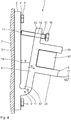
- a virtually turned upside down embodiment is in the Fig. 3 and 4 shown.
- the wall bracket l ' is designed with a designed as a flat plate mounting leg 2 without stem 5.
- the connecting web 11 to the holding leg 8 is in turn made in one piece with two legs 2, 8 and arranged in this embodiment in the lower region of the mounting leg 2.
- the holding leg 8 in its orientation substantially upwards.
- a threaded bore 14 is provided with a stop screw 15 seated therein.
- the retaining leg 8 On its side facing away from the mounting leg 2, the retaining leg 8 has a receptacle 9 for the support tube 10.
- the receptacle is formed by two opposing cheeks 19, 20 which form between them a shape adapted to the square profile of the support tube 10 form the receptacle 9.
- the receptacle 9 is formed by a cross-sectionally L-shaped profile element 21.
- the inclination angle N3 with respect to the horizontal H is practically 0 °.
- the bending angle B can be increased.
- This decreases the angle of inclination - as in Fig. 4 is shown - the larger angle N4 relative to the horizontal H a.
- the stop screw 15 is in turn screwed so that its front end 17 abuts against the mounting leg 2.
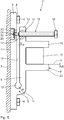
- the third embodiment of the wall bracket 1 "according to the Fig. 5 and 6 corresponds in construction of the wall bracket with mounting leg 2, connecting web 11, retaining leg 8 and 9 recording the wall bracket l 'according to the embodiment according to Fig. 3 and 4 ,
- matching components are provided with identical reference numerals and require no further discussion.
- the front end 17 of the stopper screw 15 is extended with a coaxially arranged coupling pin 22, the relatively large game a through hole 23 in the mounting leg 2 to a in the back 3 applied recess 24 passes through.
- the awning is not only - as in the embodiment according to Fig. 3 and 4 - secured against a beating, but also against a depression. Overall, the awning is so both in the Fig. 5 shown inappropriate position, as well as in the Fig. 6 secured, tilted at an inclination angle N6 relative to the horizontal H position against a beating and pressing down.
- FIG. 1 In the case of embodiments of wall bracket 1, 1 ', 1 ", which are shown in FIG. 1, mounting pieces 2, retaining legs 8, receptacle 9 and connecting web 11 are formed as one-piece profile parts that are extruded from an aluminum alloy per awning, two or more such wall brackets 1, 1 ', 1 "are fastened correspondingly distributed over the width of the awning to the building wall 7, the awning with its support tube 10 into the receptacle 9 of the respective wall bracket 1, 1', 1 "used and then set the inclination of the awning by appropriate bending action of the retaining leg 8.
Description
Die Erfindung betrifft eine Wandkonsole für eine Markise mit Neigungsverstellung.The invention relates to a wall bracket for an awning with tilt adjustment.
Ein Beispiel für eine Wandkonsole mit einer Neigungsverstellkonstruktion für die Markise ist aus der
Aus der
Eine Wandkonsole mit den Merkmalen im Oberbegriff des Anspruchs 1 ist durch
Der Erfindung liegt die Aufgabe zugrunde, eine Wandkonsole für eine Markise mit Neigungsverstellung anzugeben, deren Konstruktion gegenüber dem Stand der Technik deutlich weniger aufwändig, dabei robust ist und eine einfach durchführbare Neigungsverstellung bietet.The invention has for its object to provide a wall bracket for an awning with tilt adjustment, the construction of which compared to the prior art is significantly less expensive, while robust and offers easy to perform tilt adjustment.
Diese Aufgabe wird laut Patentanspruch 1 durch eine Wandkonsole gelöst, die umfasst:
- einen an einem Gebäudeteil, insbesondere an einer Gebäudewand, befestigbaren Montageschenkel,
- einen demgegenüber um eine horizontale Schwenkachse verstellbaren Halteschenkel, und
- eine Aufnahme am Halteschenkel für ein Tragteil, insbesondere ein Tragrohr einer Markise,
- wobei die horizontale Schwenkachse zwischen Montageschenkel und Halteschenkel durch einen einstückig mit diesen beiden Schenkeln ausgebildeten, biegbaren Verbindungssteg gebildet ist.
- a on a building part, in particular on a building wall, mountable mounting leg,
- a contrast adjustable about a horizontal pivot axis holding leg, and
- a receptacle on the retaining leg for a support member, in particular a support tube of an awning,
- wherein the horizontal pivot axis between mounting leg and retaining leg is formed by an integrally formed with these two legs, bendable connecting web.
In ihrer grundsätzlichen Ausgestaltung weist die erfindungsgemäße Wandkonstruktion also lediglich einen in Montage- und Halteschenkel sowie Verbindungssteg gegliederten Körper auf, wobei die Neigungsverstellung durch ein kontrolliertes Verformen des Verbindungssteges zwischen Montage- und Halteschenkel vorgenommen werden kann. Dazu ist kein spezielles Werkzeug notwendig. Die Biegesteifigkeit des Verbindungssteges ist dabei nach bekannten konstruktiven Auslegungskriterien an das Gewicht der Markise, deren Maße und den gewünschten konstruktiven Reserven hinsichtlich Wind- und Wasserlasten auf die Markise auszulegen.In its basic configuration, the wall construction according to the invention thus only has a body articulated in the assembly and holding limbs and the connecting web, wherein the tilt adjustment can be carried out by a controlled deformation of the connecting web between the assembly and holding limbs. No special tools are necessary for this. The flexural rigidity of the connecting web is according to known structural design criteria to the weight to design the awning, its dimensions and the required design reserves with regard to wind and water loads on the awning.
In den abhängigen Ansprüchen sind bevorzugte Ausführungsformen der Wandkonsole angegeben. So kann die Wandkonsole aus einem vorzugsweise aus einer Aluminiumlegierung stranggepressten Profilteil bestehen. Die erfindungsgemäße Wandkonsole ist damit besonders für eine rationelle und kostengünstige Massenproduktion geeignet.In the dependent claims preferred embodiments of the wall bracket are given. Thus, the wall bracket can consist of a preferably extruded from an aluminum alloy profile part. The wall bracket according to the invention is thus particularly suitable for a rational and cost-effective mass production.
Gemäß einer weiteren bevorzugten Ausführungsform kann der Biegewinkel des Halteschenkels gegenüber dem Montageschenkel zumindest in einer Schwenkrichtung durch eine Anschlagschraube fixiert sein. Damit kann die von solchen Wandkonsolen gehaltene Markise gegen ein Hochschlagen unter Windeinfluss oder Niederdrücken durch Wassersackbildung geschützt werden. Die Anschlagschraube ist dabei vorzugsweise in einer entsprechenden Gewindebohrung am freien Ende des Halteschenkels eingesetzt und liegt mit ihrem Kopf-abgewandten Vorderende in Anschlagposition am Montageschenkel an. Der durch die Anschlagposition definierte Grenz-Neigungswinkel ist damit durch eine einfache Schraubbetätigung der Anschlagschraube einstellbar.According to a further preferred embodiment, the bending angle of the retaining leg relative to the mounting leg can be fixed at least in a pivoting direction by a stop screw. Thus, the awning held by such wall brackets can be protected against beating under the influence of wind or depressed by water bag formation. The stop screw is preferably inserted in a corresponding threaded hole at the free end of the retaining leg and is located with its head-facing front end in stop position on the mounting leg. The defined by the stop position limit inclination angle is thus adjustable by a simple screw actuation of the stop screw.
Zur weiteren Verbesserung der erfindungsgemäßen Wandkonsole kann in einer Weiterbildung das Vorderende der Anschlagschraube schwenkbar und drehbar mit dem Montageschenkel gekoppelt sein. Damit ist es möglich, den Halteschenkel der Wandkonsole und damit die Markise selbst in der eingestellten Neigung sowohl gegen ein Hochschlagen als auch gegen ein Niederdrücken zu sichern.To further improve the wall bracket according to the invention, the front end of the stop screw can be pivotally and rotatably coupled to the mounting leg in a development. This makes it possible to secure the retaining leg of the wall bracket and thus the awning even in the set inclination against both a beating as well as against depression.
Diese Schwenk- und Drehkopplung des Vorderendes der Anschlagschraube mit dem Montageschenkel kann vorzugsweise dadurch realisiert werden, dass das Vorderende der Anschlagschraube einen Koppelstift aufweist, der über eine Durchgangsöffnung in Montagestellung in eine Ausnehmung in der Rückwand des Montageschenkels eingreift. Der Koppelstift ist dann mit einem Sicherungselement unter Dreh- und Schwenkspiel in dieser Ausnehmung gesichert, so dass trotz der losen Fixierung der Anschlagschraube in dieser Ausnehmung eine Verdrehung und Neigungsänderung der Schraube und damit eine Neigungsverstellung des Halteschenkels um die durch den biegbaren Verbindungssteg gebildete Schwenkachse ermöglicht wird.This pivotal and rotational coupling of the front end of the stop screw with the mounting leg can preferably be realized in that the front end of the stop screw has a coupling pin which engages via a passage opening in the mounting position in a recess in the rear wall of the mounting leg. The coupling pin is then secured with a securing element under rotation and pivoting play in this recess, so that despite the loose fixation of the stop screw in this recess a rotation and inclination change of the screw and thus a tilt adjustment of the retaining leg is made possible by the pivot axis formed by the bendable connecting web ,
Weitere Merkmale, Einzelheiten und Vorteile der Erfindung ergeben sich aus der nachfolgenden Beschreibug von Ausführungsbeispielen anhand der beigefügten Zeichnungen. Es zeigen:
- Fig. 1 und 2
- jeweils eine Seitenansicht einer Wandkonsole einer ersten Ausführungsform in zwei unterschiedlichen Neigungsstellungen des Halteschenkels,
- Fig. 3 und 4
- Seitenansichten analog
Fig. 1 und2 in einer zweiten Ausführungsform der Wandkonsole sowie - Fig. 5 und 6
- Seitenansichten analog
Fig. 1 und2 mit Teilschnitten einer dritten Ausführungsform einer Wandkonsole.
- Fig. 1 and 2
- each a side view of a wall bracket of a first embodiment in two different inclined positions of the retaining leg,
- 3 and 4
- Side views analog
Fig. 1 and2 in a second embodiment of the wall bracket as well - FIGS. 5 and 6
- Side views analog
Fig. 1 and2 with partial sections of a third embodiment of a wall bracket.
Wie aus
Ferner weist die Wandkonsole einen gegenüber dem Montageschenkel 2 um eine horizontale Schwenkachse S schwenkbaren Halteschenkel 8 auf, der ebenfalls plattenförmig ausgebildet und an seiner dem Montageschenkel 2 abgewandten Außenseite mit einer nach oben offenen Aufnahme 9 für ein Tragrohr 10 einer hier nicht näher dargestellten Markise versehen ist. Die Querschnittsform der Aufnahme 9, wie sie in
Die horizontale Schwenkachse S zwischen Montageschenkel 2 und Halteschenkel 8 ist durch einen biegbaren Verbindungssteg 11 gebildet, der einstückig mit diesen beiden Schenkeln 2, 8 ausgebildet ist. Die Wandstärke des Verbindungsstegs 11 ist gegenüber dem Halteschenkel 8 durch eine innenliegende, in der Seitenansicht ösenartig wirkende Aussparung 12 verringert. Über die Auslegung der Wandstärke w des Verbindungssteges 11 kann die Biegesteifigkeit des Verbindungssteges an die jeweiligen Gegebenheiten, wie das Gewicht, die Ausfalllänge und Breite der Markise angepasst werden.The horizontal pivot axis S between
Am freien Ende 13 des Halteschenkels 8 ist in einer gestrichelt angedeuteten Gewindebohrung 14 eine Anschlagschraube 15 von der der Gebäudewand 7 abgewandten Seite her eingesetzt, die mit ihrem dem Kopf 16 abgewandten Vorderende 17 am Montageschenkel 2 gegebenenfalls im Bereich der Vorderseite 18 des Vorbaus 5 anschlägt.At the
In der in
In
Alternativ zu der vorstehenden Betätigung kann ausgehend von der in
Der Neigungswinkel N2 der Markise gegenüber der Horizontalen H ist gegenüber der Position in
Bei der in
Bei der in
Die dritte Ausführungsform der Wandkonsole 1" gemäß den
Die in den
Claims (7)
- Wall console for an awning with angle adjustment, comprising- a mounting bracket (2) mountable to a part of a building, in particular to a building wall (7);- a retaining bracket (8) adjustable with respect to the mounting bracket (2) about a horizontal pivot axis (S); and- a receptacle (9) on the retaining bracket (8) for a support member, in particular a support pipe (10), of an awning,- characterized in that the horizontal pivot axis (S) is formed between mounting bracket (2) and retaining bracket (8) by a flexible connection web (11) formed in one piece with these two brackets (2, 8).
- Wall console according to claim 1, characterized in that it consists of an extrusion moulded shaped part.
- Wall console according to claim 2, characterized in that the shaped part consists of an extrusion mouldable aluminium alloy.
- Wall console according to one of the preceding claims, characterized in that the bending angle (B) of the retaining bracket (8) is securable in relation to the mounting bracket (2) at least in one direction of rotation (R) by means of a stop screw (15).
- Wall console according to claim 4, characterized in that the stop screw (15) is inserted in a corresponding threaded hole (14) at the free end (13) of the retaining bracket (8) and abuts, with its front end (17) remote from the head (16), against the mounting bracket (2) in a stop position.
- Wall console according to one of claims 1 to 4, characterized in that the front end (17) of the stop screw (15) is pivotably and rotatably coupled with the mounting bracket (2).
- Wall console according to claim 6, characterized in that the front end (17) of the stop screw (15) is provided with a coupling pin (22) that engages, via a through-opening (23) in the mounting bracket (2), a recess (24) in the rear side (3) thereof and is secured in the recess (24) by means of a retaining element (25) allowing rotational and pivotal clearance.
Priority Applications (1)
| Application Number | Priority Date | Filing Date | Title |
|---|---|---|---|
| PL15177190T PL3000950T3 (en) | 2014-09-29 | 2015-07-17 | Wall console for an awning with adjustable angle control |
Applications Claiming Priority (1)
| Application Number | Priority Date | Filing Date | Title |
|---|---|---|---|
| DE102014219680.9A DE102014219680A1 (en) | 2014-09-29 | 2014-09-29 | Wall bracket for awning with tilt adjustment |
Publications (2)
| Publication Number | Publication Date |
|---|---|
| EP3000950A1 EP3000950A1 (en) | 2016-03-30 |
| EP3000950B1 true EP3000950B1 (en) | 2017-03-01 |
Family
ID=53717916
Family Applications (1)
| Application Number | Title | Priority Date | Filing Date |
|---|---|---|---|
| EP15177190.4A Not-in-force EP3000950B1 (en) | 2014-09-29 | 2015-07-17 | Wall console for an awning with adjustable angle control |
Country Status (5)
| Country | Link |
|---|---|
| EP (1) | EP3000950B1 (en) |
| DE (1) | DE102014219680A1 (en) |
| DK (1) | DK3000950T3 (en) |
| ES (1) | ES2626844T3 (en) |
| PL (1) | PL3000950T3 (en) |
Cited By (1)
| Publication number | Priority date | Publication date | Assignee | Title |
|---|---|---|---|---|
| DE102020134445A1 (en) | 2020-12-21 | 2022-06-23 | Warema Renkhoff Se | Carrying bracket with pivoting bearing for attaching a housing of a sun protection system |
Families Citing this family (1)
| Publication number | Priority date | Publication date | Assignee | Title |
|---|---|---|---|---|
| DE202016104562U1 (en) | 2015-11-13 | 2016-09-01 | Schmitz-Werke Gmbh + Co Kg | Articulated arm awning with swivel joint on the support tube |
Family Cites Families (6)
| Publication number | Priority date | Publication date | Assignee | Title |
|---|---|---|---|---|
| DE7725749U1 (en) | Weinor Dieter Weiermann Gmbh & Co Kg, 5000 Koeln | |||
| DK148307C (en) * | 1976-06-01 | 1985-11-11 | Lennart Svensson | Beam to support the first change of stone by wall opening |
| DE9112342U1 (en) * | 1991-10-04 | 1992-01-02 | Warema Renkhoff Gmbh & Co Kg, 8772 Marktheidenfeld, De | |
| DE29612904U1 (en) | 1996-07-25 | 1996-09-26 | Schmitz Werke | Articulated arm awning |
| DE19644895C2 (en) * | 1996-10-29 | 1999-08-05 | Roedelbronn Gmbh | Box awning |
| DE20001537U1 (en) * | 2000-01-31 | 2000-07-06 | Roedelbronn Gmbh | Sleeve awning |
-
2014
- 2014-09-29 DE DE102014219680.9A patent/DE102014219680A1/en not_active Withdrawn
-
2015
- 2015-07-17 ES ES15177190.4T patent/ES2626844T3/en active Active
- 2015-07-17 DK DK15177190.4T patent/DK3000950T3/en active
- 2015-07-17 PL PL15177190T patent/PL3000950T3/en unknown
- 2015-07-17 EP EP15177190.4A patent/EP3000950B1/en not_active Not-in-force
Cited By (1)
| Publication number | Priority date | Publication date | Assignee | Title |
|---|---|---|---|---|
| DE102020134445A1 (en) | 2020-12-21 | 2022-06-23 | Warema Renkhoff Se | Carrying bracket with pivoting bearing for attaching a housing of a sun protection system |
Also Published As
| Publication number | Publication date |
|---|---|
| ES2626844T3 (en) | 2017-07-26 |
| EP3000950A1 (en) | 2016-03-30 |
| PL3000950T3 (en) | 2017-08-31 |
| DK3000950T3 (en) | 2017-06-19 |
| DE102014219680A1 (en) | 2016-03-31 |
Similar Documents
| Publication | Publication Date | Title |
|---|---|---|
| EP0445591A1 (en) | Device for connecting a steering column of a motor vehicle to the stub shaft of a steering gear | |
| EP2267237B1 (en) | Fastening device | |
| EP3341538B1 (en) | Fanned vehicle awning | |
| EP1544379B1 (en) | Clamping device | |
| EP3000950B1 (en) | Wall console for an awning with adjustable angle control | |
| CH642423A5 (en) | SUPPORTING JOINT FOR JOINT ARMS ON AWNINGS. | |
| EP3755602A1 (en) | Steering column for a motor vehicle | |
| DE102006034876B4 (en) | Presentation support frame | |
| EP0409839A1 (en) | Tilting limiter for roller blinds. | |
| DE10061819A1 (en) | Articulated arm awning | |
| EP3090654A1 (en) | Swivel device for a tray holder on a corner cabinet unit | |
| DE202007015491U1 (en) | Angle adjustable bicycle stem | |
| DE102005050639B4 (en) | Device for locking a door of a housing | |
| DE10216478B4 (en) | Articulated arm awning | |
| EP2172610A1 (en) | Hinge mounting part | |
| EP1887151B1 (en) | Articulation fitting | |
| DE102006062326A1 (en) | Support device for a hinge of a closing unit | |
| EP1760221B1 (en) | Arrangement for adjusting the inclination of the arms of an awning with articulated arms | |
| DE102006051862B4 (en) | carriage | |
| EP1640541A2 (en) | Device for stopping a swingable apparatus, in particular a door or window | |
| EP3701835B1 (en) | Device for connecting a front element to a side element of a movable part of a piece of furniture | |
| DE602005005650T2 (en) | ARM ADJUSTING DEVICE FOR AWNING | |
| EP1724411B1 (en) | Awning | |
| EP3538728B1 (en) | Pivot bearing for a side flap of a vehicle | |
| EP3146134B1 (en) | Adjustable vertical reinforcement element for a door or window sash that is movable from one plane to a parallel plane |
Legal Events
| Date | Code | Title | Description |
|---|---|---|---|
| PUAI | Public reference made under article 153(3) epc to a published international application that has entered the european phase |
Free format text: ORIGINAL CODE: 0009012 |
|
| AK | Designated contracting states |
Kind code of ref document: A1 Designated state(s): AL AT BE BG CH CY CZ DE DK EE ES FI FR GB GR HR HU IE IS IT LI LT LU LV MC MK MT NL NO PL PT RO RS SE SI SK SM TR |
|
| AX | Request for extension of the european patent |
Extension state: BA ME |
|
| 17P | Request for examination filed |
Effective date: 20160518 |
|
| RBV | Designated contracting states (corrected) |
Designated state(s): AL AT BE BG CH CY CZ DE DK EE ES FI FR GB GR HR HU IE IS IT LI LT LU LV MC MK MT NL NO PL PT RO RS SE SI SK SM TR |
|
| GRAP | Despatch of communication of intention to grant a patent |
Free format text: ORIGINAL CODE: EPIDOSNIGR1 |
|
| INTG | Intention to grant announced |
Effective date: 20161110 |
|
| GRAS | Grant fee paid |
Free format text: ORIGINAL CODE: EPIDOSNIGR3 |
|
| GRAA | (expected) grant |
Free format text: ORIGINAL CODE: 0009210 |
|
| AK | Designated contracting states |
Kind code of ref document: B1 Designated state(s): AL AT BE BG CH CY CZ DE DK EE ES FI FR GB GR HR HU IE IS IT LI LT LU LV MC MK MT NL NO PL PT RO RS SE SI SK SM TR |
|
| REG | Reference to a national code |
Ref country code: GB Ref legal event code: FG4D Free format text: NOT ENGLISH |
|
| REG | Reference to a national code |
Ref country code: AT Ref legal event code: REF Ref document number: 871531 Country of ref document: AT Kind code of ref document: T Effective date: 20170315 Ref country code: CH Ref legal event code: EP |
|
| REG | Reference to a national code |
Ref country code: IE Ref legal event code: FG4D Free format text: LANGUAGE OF EP DOCUMENT: GERMAN |
|
| REG | Reference to a national code |
Ref country code: DE Ref legal event code: R096 Ref document number: 502015000640 Country of ref document: DE |
|
| REG | Reference to a national code |
Ref country code: NL Ref legal event code: FP |
|
| REG | Reference to a national code |
Ref country code: SE Ref legal event code: TRGR |
|
| REG | Reference to a national code |
Ref country code: DK Ref legal event code: T3 Effective date: 20170612 |
|
| REG | Reference to a national code |
Ref country code: LT Ref legal event code: MG4D |
|
| REG | Reference to a national code |
Ref country code: FR Ref legal event code: PLFP Year of fee payment: 3 |
|
| REG | Reference to a national code |
Ref country code: ES Ref legal event code: FG2A Ref document number: 2626844 Country of ref document: ES Kind code of ref document: T3 Effective date: 20170726 |
|
| PG25 | Lapsed in a contracting state [announced via postgrant information from national office to epo] |
Ref country code: FI Free format text: LAPSE BECAUSE OF FAILURE TO SUBMIT A TRANSLATION OF THE DESCRIPTION OR TO PAY THE FEE WITHIN THE PRESCRIBED TIME-LIMIT Effective date: 20170301 Ref country code: HR Free format text: LAPSE BECAUSE OF FAILURE TO SUBMIT A TRANSLATION OF THE DESCRIPTION OR TO PAY THE FEE WITHIN THE PRESCRIBED TIME-LIMIT Effective date: 20170301 Ref country code: NO Free format text: LAPSE BECAUSE OF FAILURE TO SUBMIT A TRANSLATION OF THE DESCRIPTION OR TO PAY THE FEE WITHIN THE PRESCRIBED TIME-LIMIT Effective date: 20170601 Ref country code: GR Free format text: LAPSE BECAUSE OF FAILURE TO SUBMIT A TRANSLATION OF THE DESCRIPTION OR TO PAY THE FEE WITHIN THE PRESCRIBED TIME-LIMIT Effective date: 20170602 Ref country code: LT Free format text: LAPSE BECAUSE OF FAILURE TO SUBMIT A TRANSLATION OF THE DESCRIPTION OR TO PAY THE FEE WITHIN THE PRESCRIBED TIME-LIMIT Effective date: 20170301 |
|
| PG25 | Lapsed in a contracting state [announced via postgrant information from national office to epo] |
Ref country code: LV Free format text: LAPSE BECAUSE OF FAILURE TO SUBMIT A TRANSLATION OF THE DESCRIPTION OR TO PAY THE FEE WITHIN THE PRESCRIBED TIME-LIMIT Effective date: 20170301 Ref country code: RS Free format text: LAPSE BECAUSE OF FAILURE TO SUBMIT A TRANSLATION OF THE DESCRIPTION OR TO PAY THE FEE WITHIN THE PRESCRIBED TIME-LIMIT Effective date: 20170301 Ref country code: BG Free format text: LAPSE BECAUSE OF FAILURE TO SUBMIT A TRANSLATION OF THE DESCRIPTION OR TO PAY THE FEE WITHIN THE PRESCRIBED TIME-LIMIT Effective date: 20170601 |
|
| PG25 | Lapsed in a contracting state [announced via postgrant information from national office to epo] |
Ref country code: CZ Free format text: LAPSE BECAUSE OF FAILURE TO SUBMIT A TRANSLATION OF THE DESCRIPTION OR TO PAY THE FEE WITHIN THE PRESCRIBED TIME-LIMIT Effective date: 20170301 Ref country code: SK Free format text: LAPSE BECAUSE OF FAILURE TO SUBMIT A TRANSLATION OF THE DESCRIPTION OR TO PAY THE FEE WITHIN THE PRESCRIBED TIME-LIMIT Effective date: 20170301 Ref country code: EE Free format text: LAPSE BECAUSE OF FAILURE TO SUBMIT A TRANSLATION OF THE DESCRIPTION OR TO PAY THE FEE WITHIN THE PRESCRIBED TIME-LIMIT Effective date: 20170301 Ref country code: RO Free format text: LAPSE BECAUSE OF FAILURE TO SUBMIT A TRANSLATION OF THE DESCRIPTION OR TO PAY THE FEE WITHIN THE PRESCRIBED TIME-LIMIT Effective date: 20170301 |
|
| PG25 | Lapsed in a contracting state [announced via postgrant information from national office to epo] |
Ref country code: IS Free format text: LAPSE BECAUSE OF FAILURE TO SUBMIT A TRANSLATION OF THE DESCRIPTION OR TO PAY THE FEE WITHIN THE PRESCRIBED TIME-LIMIT Effective date: 20170701 Ref country code: PT Free format text: LAPSE BECAUSE OF FAILURE TO SUBMIT A TRANSLATION OF THE DESCRIPTION OR TO PAY THE FEE WITHIN THE PRESCRIBED TIME-LIMIT Effective date: 20170703 Ref country code: SM Free format text: LAPSE BECAUSE OF FAILURE TO SUBMIT A TRANSLATION OF THE DESCRIPTION OR TO PAY THE FEE WITHIN THE PRESCRIBED TIME-LIMIT Effective date: 20170301 |
|
| REG | Reference to a national code |
Ref country code: DE Ref legal event code: R097 Ref document number: 502015000640 Country of ref document: DE |
|
| PLBE | No opposition filed within time limit |
Free format text: ORIGINAL CODE: 0009261 |
|
| STAA | Information on the status of an ep patent application or granted ep patent |
Free format text: STATUS: NO OPPOSITION FILED WITHIN TIME LIMIT |
|
| 26N | No opposition filed |
Effective date: 20171204 |
|
| PG25 | Lapsed in a contracting state [announced via postgrant information from national office to epo] |
Ref country code: SI Free format text: LAPSE BECAUSE OF FAILURE TO SUBMIT A TRANSLATION OF THE DESCRIPTION OR TO PAY THE FEE WITHIN THE PRESCRIBED TIME-LIMIT Effective date: 20170301 |
|
| REG | Reference to a national code |
Ref country code: IE Ref legal event code: MM4A |
|
| PG25 | Lapsed in a contracting state [announced via postgrant information from national office to epo] |
Ref country code: IE Free format text: LAPSE BECAUSE OF NON-PAYMENT OF DUE FEES Effective date: 20170717 |
|
| PG25 | Lapsed in a contracting state [announced via postgrant information from national office to epo] |
Ref country code: LU Free format text: LAPSE BECAUSE OF NON-PAYMENT OF DUE FEES Effective date: 20170717 |
|
| REG | Reference to a national code |
Ref country code: FR Ref legal event code: PLFP Year of fee payment: 4 |
|
| PG25 | Lapsed in a contracting state [announced via postgrant information from national office to epo] |
Ref country code: MT Free format text: LAPSE BECAUSE OF FAILURE TO SUBMIT A TRANSLATION OF THE DESCRIPTION OR TO PAY THE FEE WITHIN THE PRESCRIBED TIME-LIMIT Effective date: 20170301 |
|
| PG25 | Lapsed in a contracting state [announced via postgrant information from national office to epo] |
Ref country code: MC Free format text: LAPSE BECAUSE OF FAILURE TO SUBMIT A TRANSLATION OF THE DESCRIPTION OR TO PAY THE FEE WITHIN THE PRESCRIBED TIME-LIMIT Effective date: 20170301 Ref country code: HU Free format text: LAPSE BECAUSE OF FAILURE TO SUBMIT A TRANSLATION OF THE DESCRIPTION OR TO PAY THE FEE WITHIN THE PRESCRIBED TIME-LIMIT; INVALID AB INITIO Effective date: 20150717 |
|
| REG | Reference to a national code |
Ref country code: DE Ref legal event code: R082 Ref document number: 502015000640 Country of ref document: DE Representative=s name: RAU, SCHNECK & HUEBNER PATENTANWAELTE RECHTSAN, DE Ref country code: DE Ref legal event code: R081 Ref document number: 502015000640 Country of ref document: DE Owner name: MARKILUX GMBH + CO. KG, DE Free format text: FORMER OWNER: SCHMITZ-WERKE GMBH + CO KG, 48282 EMSDETTEN, DE |
|
| PG25 | Lapsed in a contracting state [announced via postgrant information from national office to epo] |
Ref country code: CY Free format text: LAPSE BECAUSE OF FAILURE TO SUBMIT A TRANSLATION OF THE DESCRIPTION OR TO PAY THE FEE WITHIN THE PRESCRIBED TIME-LIMIT Effective date: 20170301 |
|
| PG25 | Lapsed in a contracting state [announced via postgrant information from national office to epo] |
Ref country code: MK Free format text: LAPSE BECAUSE OF FAILURE TO SUBMIT A TRANSLATION OF THE DESCRIPTION OR TO PAY THE FEE WITHIN THE PRESCRIBED TIME-LIMIT Effective date: 20170301 |
|
| PG25 | Lapsed in a contracting state [announced via postgrant information from national office to epo] |
Ref country code: TR Free format text: LAPSE BECAUSE OF FAILURE TO SUBMIT A TRANSLATION OF THE DESCRIPTION OR TO PAY THE FEE WITHIN THE PRESCRIBED TIME-LIMIT Effective date: 20170301 |
|
| PG25 | Lapsed in a contracting state [announced via postgrant information from national office to epo] |
Ref country code: AL Free format text: LAPSE BECAUSE OF FAILURE TO SUBMIT A TRANSLATION OF THE DESCRIPTION OR TO PAY THE FEE WITHIN THE PRESCRIBED TIME-LIMIT Effective date: 20170301 |
|
| REG | Reference to a national code |
Ref country code: ES Ref legal event code: PC2A Owner name: MARKILUX GMBH + CO. KG Effective date: 20200731 |
|
| REG | Reference to a national code |
Ref country code: NL Ref legal event code: PD Owner name: MARKILUX GMBH + CO. KG; DE Free format text: DETAILS ASSIGNMENT: CHANGE OF OWNER(S), ASSIGNMENT; FORMER OWNER NAME: SCHMITZ-WERKE GMBH + CO. KG Effective date: 20200615 |
|
| REG | Reference to a national code |
Ref country code: BE Ref legal event code: PD Owner name: MARKILUX GMBH + CO. KG; DE Free format text: DETAILS ASSIGNMENT: CHANGE OF OWNER(S), CESSION; FORMER OWNER NAME: SCHMITZ-WERKE GMBH + CO. KG Effective date: 20200723 |
|
| REG | Reference to a national code |
Ref country code: CH Ref legal event code: PUE Owner name: MARKILUX GMBH + CO. KG, DE Free format text: FORMER OWNER: SCHMITZ-WERKE GMBH + CO. KG, DE |
|
| REG | Reference to a national code |
Ref country code: GB Ref legal event code: 732E Free format text: REGISTERED BETWEEN 20200917 AND 20200923 |
|
| PGFP | Annual fee paid to national office [announced via postgrant information from national office to epo] |
Ref country code: CH Payment date: 20210618 Year of fee payment: 7 |
|
| PGFP | Annual fee paid to national office [announced via postgrant information from national office to epo] |
Ref country code: NL Payment date: 20210721 Year of fee payment: 7 |
|
| PGFP | Annual fee paid to national office [announced via postgrant information from national office to epo] |
Ref country code: AT Payment date: 20210622 Year of fee payment: 7 Ref country code: FR Payment date: 20210722 Year of fee payment: 7 Ref country code: IT Payment date: 20210730 Year of fee payment: 7 |
|
| PGFP | Annual fee paid to national office [announced via postgrant information from national office to epo] |
Ref country code: SE Payment date: 20210721 Year of fee payment: 7 Ref country code: ES Payment date: 20210819 Year of fee payment: 7 Ref country code: DK Payment date: 20210721 Year of fee payment: 7 Ref country code: DE Payment date: 20210924 Year of fee payment: 7 Ref country code: BE Payment date: 20210721 Year of fee payment: 7 Ref country code: GB Payment date: 20210722 Year of fee payment: 7 Ref country code: PL Payment date: 20210705 Year of fee payment: 7 |
|
| REG | Reference to a national code |
Ref country code: DE Ref legal event code: R119 Ref document number: 502015000640 Country of ref document: DE |
|
| REG | Reference to a national code |
Ref country code: DK Ref legal event code: EBP Effective date: 20220731 |
|
| REG | Reference to a national code |
Ref country code: CH Ref legal event code: PL Ref country code: SE Ref legal event code: EUG |
|
| REG | Reference to a national code |
Ref country code: NL Ref legal event code: MM Effective date: 20220801 |
|
| REG | Reference to a national code |
Ref country code: AT Ref legal event code: MM01 Ref document number: 871531 Country of ref document: AT Kind code of ref document: T Effective date: 20220717 |
|
| GBPC | Gb: european patent ceased through non-payment of renewal fee |
Effective date: 20220717 |
|
| REG | Reference to a national code |
Ref country code: BE Ref legal event code: MM Effective date: 20220731 |
|
| PG25 | Lapsed in a contracting state [announced via postgrant information from national office to epo] |
Ref country code: SE Free format text: LAPSE BECAUSE OF NON-PAYMENT OF DUE FEES Effective date: 20220718 Ref country code: LI Free format text: LAPSE BECAUSE OF NON-PAYMENT OF DUE FEES Effective date: 20220731 Ref country code: FR Free format text: LAPSE BECAUSE OF NON-PAYMENT OF DUE FEES Effective date: 20220731 Ref country code: CH Free format text: LAPSE BECAUSE OF NON-PAYMENT OF DUE FEES Effective date: 20220731 Ref country code: AT Free format text: LAPSE BECAUSE OF NON-PAYMENT OF DUE FEES Effective date: 20220717 |
|
| PG25 | Lapsed in a contracting state [announced via postgrant information from national office to epo] |
Ref country code: GB Free format text: LAPSE BECAUSE OF NON-PAYMENT OF DUE FEES Effective date: 20220717 Ref country code: DE Free format text: LAPSE BECAUSE OF NON-PAYMENT OF DUE FEES Effective date: 20230201 Ref country code: BE Free format text: LAPSE BECAUSE OF NON-PAYMENT OF DUE FEES Effective date: 20220731 |
|
| PG25 | Lapsed in a contracting state [announced via postgrant information from national office to epo] |
Ref country code: NL Free format text: LAPSE BECAUSE OF NON-PAYMENT OF DUE FEES Effective date: 20220801 |
|
| PG25 | Lapsed in a contracting state [announced via postgrant information from national office to epo] |
Ref country code: IT Free format text: LAPSE BECAUSE OF NON-PAYMENT OF DUE FEES Effective date: 20220717 Ref country code: DK Free format text: LAPSE BECAUSE OF NON-PAYMENT OF DUE FEES Effective date: 20220731 |
|
| REG | Reference to a national code |
Ref country code: ES Ref legal event code: FD2A Effective date: 20230830 |
|
| PG25 | Lapsed in a contracting state [announced via postgrant information from national office to epo] |
Ref country code: ES Free format text: LAPSE BECAUSE OF NON-PAYMENT OF DUE FEES Effective date: 20220718 |
|
| PG25 | Lapsed in a contracting state [announced via postgrant information from national office to epo] |
Ref country code: PL Free format text: LAPSE BECAUSE OF NON-PAYMENT OF DUE FEES Effective date: 20220717 |