EP3000446B1 - Kathetersystem und verfahren zur herstellung eines solchen - Google Patents
Kathetersystem und verfahren zur herstellung eines solchen Download PDFInfo
- Publication number
- EP3000446B1 EP3000446B1 EP15173651.9A EP15173651A EP3000446B1 EP 3000446 B1 EP3000446 B1 EP 3000446B1 EP 15173651 A EP15173651 A EP 15173651A EP 3000446 B1 EP3000446 B1 EP 3000446B1
- Authority
- EP
- European Patent Office
- Prior art keywords
- catheter system
- feed tube
- tip portion
- functional element
- tip
- Prior art date
- Legal status (The legal status is an assumption and is not a legal conclusion. Google has not performed a legal analysis and makes no representation as to the accuracy of the status listed.)
- Active
Links
- 238000004519 manufacturing process Methods 0.000 title claims description 11
- 239000004810 polytetrafluoroethylene Substances 0.000 claims description 26
- 229920001343 polytetrafluoroethylene Polymers 0.000 claims description 26
- 239000000853 adhesive Substances 0.000 claims description 13
- 230000001070 adhesive effect Effects 0.000 claims description 13
- 238000000034 method Methods 0.000 claims description 13
- 235000021355 Stearic acid Nutrition 0.000 claims description 9
- 235000014113 dietary fatty acids Nutrition 0.000 claims description 9
- 239000000194 fatty acid Substances 0.000 claims description 9
- 229930195729 fatty acid Natural products 0.000 claims description 9
- 150000004665 fatty acids Chemical class 0.000 claims description 9
- QIQXTHQIDYTFRH-UHFFFAOYSA-N octadecanoic acid Chemical compound CCCCCCCCCCCCCCCCCC(O)=O QIQXTHQIDYTFRH-UHFFFAOYSA-N 0.000 claims description 9
- OQCDKBAXFALNLD-UHFFFAOYSA-N octadecanoic acid Natural products CCCCCCCC(C)CCCCCCCCC(O)=O OQCDKBAXFALNLD-UHFFFAOYSA-N 0.000 claims description 9
- 239000008117 stearic acid Substances 0.000 claims description 9
- 238000002844 melting Methods 0.000 claims description 4
- 230000008018 melting Effects 0.000 claims description 4
- 239000000654 additive Substances 0.000 claims description 3
- ZQPPMHVWECSIRJ-KTKRTIGZSA-N oleic acid group Chemical group C(CCCCCCC\C=C/CCCCCCCC)(=O)O ZQPPMHVWECSIRJ-KTKRTIGZSA-N 0.000 claims description 3
- 229920000036 polyvinylpyrrolidone Polymers 0.000 claims description 3
- 235000013855 polyvinylpyrrolidone Nutrition 0.000 claims description 3
- 230000000996 additive effect Effects 0.000 claims description 2
- 239000001267 polyvinylpyrrolidone Substances 0.000 claims description 2
- LFQSCWFLJHTTHZ-UHFFFAOYSA-N Ethanol Chemical compound CCO LFQSCWFLJHTTHZ-UHFFFAOYSA-N 0.000 claims 1
- 238000000465 moulding Methods 0.000 claims 1
- 229920006395 saturated elastomer Polymers 0.000 claims 1
- 239000000463 material Substances 0.000 description 10
- 239000011159 matrix material Substances 0.000 description 5
- 230000006835 compression Effects 0.000 description 3
- 238000007906 compression Methods 0.000 description 3
- 238000013461 design Methods 0.000 description 3
- WRIDQFICGBMAFQ-UHFFFAOYSA-N (E)-8-Octadecenoic acid Natural products CCCCCCCCCC=CCCCCCCC(O)=O WRIDQFICGBMAFQ-UHFFFAOYSA-N 0.000 description 2
- LQJBNNIYVWPHFW-UHFFFAOYSA-N 20:1omega9c fatty acid Natural products CCCCCCCCCCC=CCCCCCCCC(O)=O LQJBNNIYVWPHFW-UHFFFAOYSA-N 0.000 description 2
- QSBYPNXLFMSGKH-UHFFFAOYSA-N 9-Heptadecensaeure Natural products CCCCCCCC=CCCCCCCCC(O)=O QSBYPNXLFMSGKH-UHFFFAOYSA-N 0.000 description 2
- ZQPPMHVWECSIRJ-UHFFFAOYSA-N Oleic acid Natural products CCCCCCCCC=CCCCCCCCC(O)=O ZQPPMHVWECSIRJ-UHFFFAOYSA-N 0.000 description 2
- 239000005642 Oleic acid Substances 0.000 description 2
- 239000002131 composite material Substances 0.000 description 2
- 238000001816 cooling Methods 0.000 description 2
- 238000002513 implantation Methods 0.000 description 2
- QXJSBBXBKPUZAA-UHFFFAOYSA-N isooleic acid Natural products CCCCCCCC=CCCCCCCCCC(O)=O QXJSBBXBKPUZAA-UHFFFAOYSA-N 0.000 description 2
- HLXZNVUGXRDIFK-UHFFFAOYSA-N nickel titanium Chemical compound [Ti].[Ti].[Ti].[Ti].[Ti].[Ti].[Ti].[Ti].[Ti].[Ti].[Ti].[Ni].[Ni].[Ni].[Ni].[Ni].[Ni].[Ni].[Ni].[Ni].[Ni].[Ni].[Ni].[Ni].[Ni] HLXZNVUGXRDIFK-UHFFFAOYSA-N 0.000 description 2
- 229910001000 nickel titanium Inorganic materials 0.000 description 2
- 229920003023 plastic Polymers 0.000 description 2
- 239000004033 plastic Substances 0.000 description 2
- 239000004830 Super Glue Substances 0.000 description 1
- 238000004026 adhesive bonding Methods 0.000 description 1
- 150000001336 alkenes Chemical class 0.000 description 1
- 210000004204 blood vessel Anatomy 0.000 description 1
- 238000006243 chemical reaction Methods 0.000 description 1
- 238000000748 compression moulding Methods 0.000 description 1
- 238000007796 conventional method Methods 0.000 description 1
- 230000032798 delamination Effects 0.000 description 1
- 230000001419 dependent effect Effects 0.000 description 1
- 238000011161 development Methods 0.000 description 1
- 230000018109 developmental process Effects 0.000 description 1
- 238000001035 drying Methods 0.000 description 1
- 230000005489 elastic deformation Effects 0.000 description 1
- 235000004626 essential fatty acids Nutrition 0.000 description 1
- FGBJXOREULPLGL-UHFFFAOYSA-N ethyl cyanoacrylate Chemical compound CCOC(=O)C(=C)C#N FGBJXOREULPLGL-UHFFFAOYSA-N 0.000 description 1
- 239000000835 fiber Substances 0.000 description 1
- 239000003292 glue Substances 0.000 description 1
- 230000002209 hydrophobic effect Effects 0.000 description 1
- 238000005470 impregnation Methods 0.000 description 1
- 208000014674 injury Diseases 0.000 description 1
- 238000003780 insertion Methods 0.000 description 1
- 230000037431 insertion Effects 0.000 description 1
- 238000010327 methods by industry Methods 0.000 description 1
- JRZJOMJEPLMPRA-UHFFFAOYSA-N olefin Natural products CCCCCCCC=C JRZJOMJEPLMPRA-UHFFFAOYSA-N 0.000 description 1
- 229920000642 polymer Polymers 0.000 description 1
- 239000002244 precipitate Substances 0.000 description 1
- 238000005245 sintering Methods 0.000 description 1
- 238000001356 surgical procedure Methods 0.000 description 1
- 230000008733 trauma Effects 0.000 description 1
- 230000000472 traumatic effect Effects 0.000 description 1
- 230000002792 vascular Effects 0.000 description 1
Images

Classifications
-
- A—HUMAN NECESSITIES
- A61—MEDICAL OR VETERINARY SCIENCE; HYGIENE
- A61L—METHODS OR APPARATUS FOR STERILISING MATERIALS OR OBJECTS IN GENERAL; DISINFECTION, STERILISATION OR DEODORISATION OF AIR; CHEMICAL ASPECTS OF BANDAGES, DRESSINGS, ABSORBENT PADS OR SURGICAL ARTICLES; MATERIALS FOR BANDAGES, DRESSINGS, ABSORBENT PADS OR SURGICAL ARTICLES
- A61L29/00—Materials for catheters, medical tubing, cannulae, or endoscopes or for coating catheters
- A61L29/04—Macromolecular materials
- A61L29/041—Macromolecular materials obtained by reactions only involving carbon-to-carbon unsaturated bonds
-
- A—HUMAN NECESSITIES
- A61—MEDICAL OR VETERINARY SCIENCE; HYGIENE
- A61F—FILTERS IMPLANTABLE INTO BLOOD VESSELS; PROSTHESES; DEVICES PROVIDING PATENCY TO, OR PREVENTING COLLAPSING OF, TUBULAR STRUCTURES OF THE BODY, e.g. STENTS; ORTHOPAEDIC, NURSING OR CONTRACEPTIVE DEVICES; FOMENTATION; TREATMENT OR PROTECTION OF EYES OR EARS; BANDAGES, DRESSINGS OR ABSORBENT PADS; FIRST-AID KITS
- A61F2/00—Filters implantable into blood vessels; Prostheses, i.e. artificial substitutes or replacements for parts of the body; Appliances for connecting them with the body; Devices providing patency to, or preventing collapsing of, tubular structures of the body, e.g. stents
- A61F2/95—Instruments specially adapted for placement or removal of stents or stent-grafts
- A61F2/962—Instruments specially adapted for placement or removal of stents or stent-grafts having an outer sleeve
- A61F2/966—Instruments specially adapted for placement or removal of stents or stent-grafts having an outer sleeve with relative longitudinal movement between outer sleeve and prosthesis, e.g. using a push rod
-
- A—HUMAN NECESSITIES
- A61—MEDICAL OR VETERINARY SCIENCE; HYGIENE
- A61F—FILTERS IMPLANTABLE INTO BLOOD VESSELS; PROSTHESES; DEVICES PROVIDING PATENCY TO, OR PREVENTING COLLAPSING OF, TUBULAR STRUCTURES OF THE BODY, e.g. STENTS; ORTHOPAEDIC, NURSING OR CONTRACEPTIVE DEVICES; FOMENTATION; TREATMENT OR PROTECTION OF EYES OR EARS; BANDAGES, DRESSINGS OR ABSORBENT PADS; FIRST-AID KITS
- A61F2/00—Filters implantable into blood vessels; Prostheses, i.e. artificial substitutes or replacements for parts of the body; Appliances for connecting them with the body; Devices providing patency to, or preventing collapsing of, tubular structures of the body, e.g. stents
- A61F2/82—Devices providing patency to, or preventing collapsing of, tubular structures of the body, e.g. stents
-
- A—HUMAN NECESSITIES
- A61—MEDICAL OR VETERINARY SCIENCE; HYGIENE
- A61L—METHODS OR APPARATUS FOR STERILISING MATERIALS OR OBJECTS IN GENERAL; DISINFECTION, STERILISATION OR DEODORISATION OF AIR; CHEMICAL ASPECTS OF BANDAGES, DRESSINGS, ABSORBENT PADS OR SURGICAL ARTICLES; MATERIALS FOR BANDAGES, DRESSINGS, ABSORBENT PADS OR SURGICAL ARTICLES
- A61L29/00—Materials for catheters, medical tubing, cannulae, or endoscopes or for coating catheters
- A61L29/04—Macromolecular materials
- A61L29/06—Macromolecular materials obtained otherwise than by reactions only involving carbon-to-carbon unsaturated bonds
-
- A—HUMAN NECESSITIES
- A61—MEDICAL OR VETERINARY SCIENCE; HYGIENE
- A61L—METHODS OR APPARATUS FOR STERILISING MATERIALS OR OBJECTS IN GENERAL; DISINFECTION, STERILISATION OR DEODORISATION OF AIR; CHEMICAL ASPECTS OF BANDAGES, DRESSINGS, ABSORBENT PADS OR SURGICAL ARTICLES; MATERIALS FOR BANDAGES, DRESSINGS, ABSORBENT PADS OR SURGICAL ARTICLES
- A61L29/00—Materials for catheters, medical tubing, cannulae, or endoscopes or for coating catheters
- A61L29/14—Materials characterised by their function or physical properties, e.g. lubricating compositions
- A61L29/146—Porous materials, e.g. foams or sponges
-
- A—HUMAN NECESSITIES
- A61—MEDICAL OR VETERINARY SCIENCE; HYGIENE
- A61L—METHODS OR APPARATUS FOR STERILISING MATERIALS OR OBJECTS IN GENERAL; DISINFECTION, STERILISATION OR DEODORISATION OF AIR; CHEMICAL ASPECTS OF BANDAGES, DRESSINGS, ABSORBENT PADS OR SURGICAL ARTICLES; MATERIALS FOR BANDAGES, DRESSINGS, ABSORBENT PADS OR SURGICAL ARTICLES
- A61L29/00—Materials for catheters, medical tubing, cannulae, or endoscopes or for coating catheters
- A61L29/14—Materials characterised by their function or physical properties, e.g. lubricating compositions
- A61L29/16—Biologically active materials, e.g. therapeutic substances
-
- A—HUMAN NECESSITIES
- A61—MEDICAL OR VETERINARY SCIENCE; HYGIENE
- A61M—DEVICES FOR INTRODUCING MEDIA INTO, OR ONTO, THE BODY; DEVICES FOR TRANSDUCING BODY MEDIA OR FOR TAKING MEDIA FROM THE BODY; DEVICES FOR PRODUCING OR ENDING SLEEP OR STUPOR
- A61M25/00—Catheters; Hollow probes
- A61M25/10—Balloon catheters
- A61M25/1011—Multiple balloon catheters
-
- A—HUMAN NECESSITIES
- A61—MEDICAL OR VETERINARY SCIENCE; HYGIENE
- A61L—METHODS OR APPARATUS FOR STERILISING MATERIALS OR OBJECTS IN GENERAL; DISINFECTION, STERILISATION OR DEODORISATION OF AIR; CHEMICAL ASPECTS OF BANDAGES, DRESSINGS, ABSORBENT PADS OR SURGICAL ARTICLES; MATERIALS FOR BANDAGES, DRESSINGS, ABSORBENT PADS OR SURGICAL ARTICLES
- A61L2300/00—Biologically active materials used in bandages, wound dressings, absorbent pads or medical devices
- A61L2300/60—Biologically active materials used in bandages, wound dressings, absorbent pads or medical devices characterised by a special physical form
- A61L2300/606—Coatings
-
- A—HUMAN NECESSITIES
- A61—MEDICAL OR VETERINARY SCIENCE; HYGIENE
- A61M—DEVICES FOR INTRODUCING MEDIA INTO, OR ONTO, THE BODY; DEVICES FOR TRANSDUCING BODY MEDIA OR FOR TAKING MEDIA FROM THE BODY; DEVICES FOR PRODUCING OR ENDING SLEEP OR STUPOR
- A61M25/00—Catheters; Hollow probes
- A61M25/01—Introducing, guiding, advancing, emplacing or holding catheters
- A61M25/06—Body-piercing guide needles or the like
- A61M25/0662—Guide tubes
- A61M2025/0681—Systems with catheter and outer tubing, e.g. sheath, sleeve or guide tube
-
- A—HUMAN NECESSITIES
- A61—MEDICAL OR VETERINARY SCIENCE; HYGIENE
- A61M—DEVICES FOR INTRODUCING MEDIA INTO, OR ONTO, THE BODY; DEVICES FOR TRANSDUCING BODY MEDIA OR FOR TAKING MEDIA FROM THE BODY; DEVICES FOR PRODUCING OR ENDING SLEEP OR STUPOR
- A61M25/00—Catheters; Hollow probes
- A61M25/10—Balloon catheters
- A61M2025/1043—Balloon catheters with special features or adapted for special applications
- A61M2025/105—Balloon catheters with special features or adapted for special applications having a balloon suitable for drug delivery, e.g. by using holes for delivery, drug coating or membranes
-
- A—HUMAN NECESSITIES
- A61—MEDICAL OR VETERINARY SCIENCE; HYGIENE
- A61M—DEVICES FOR INTRODUCING MEDIA INTO, OR ONTO, THE BODY; DEVICES FOR TRANSDUCING BODY MEDIA OR FOR TAKING MEDIA FROM THE BODY; DEVICES FOR PRODUCING OR ENDING SLEEP OR STUPOR
- A61M25/00—Catheters; Hollow probes
- A61M25/10—Balloon catheters
- A61M2025/1043—Balloon catheters with special features or adapted for special applications
- A61M2025/1061—Balloon catheters with special features or adapted for special applications having separate inflations tubes, e.g. coaxial tubes or tubes otherwise arranged apart from the catheter tube
-
- A—HUMAN NECESSITIES
- A61—MEDICAL OR VETERINARY SCIENCE; HYGIENE
- A61M—DEVICES FOR INTRODUCING MEDIA INTO, OR ONTO, THE BODY; DEVICES FOR TRANSDUCING BODY MEDIA OR FOR TAKING MEDIA FROM THE BODY; DEVICES FOR PRODUCING OR ENDING SLEEP OR STUPOR
- A61M25/00—Catheters; Hollow probes
- A61M25/10—Balloon catheters
- A61M2025/1043—Balloon catheters with special features or adapted for special applications
- A61M2025/1081—Balloon catheters with special features or adapted for special applications having sheaths or the like for covering the balloon but not forming a permanent part of the balloon, e.g. retractable, dissolvable or tearable sheaths
-
- A—HUMAN NECESSITIES
- A61—MEDICAL OR VETERINARY SCIENCE; HYGIENE
- A61M—DEVICES FOR INTRODUCING MEDIA INTO, OR ONTO, THE BODY; DEVICES FOR TRANSDUCING BODY MEDIA OR FOR TAKING MEDIA FROM THE BODY; DEVICES FOR PRODUCING OR ENDING SLEEP OR STUPOR
- A61M25/00—Catheters; Hollow probes
- A61M25/10—Balloon catheters
- A61M25/1002—Balloon catheters characterised by balloon shape
Definitions
- the invention relates to a catheter system with a functional element at the distal end, a supply tube surrounding the functional element with its distal end and a pushing element abutting the proximal end of the functional element for advancing the functional element out of the supply tube in order to perform the function of the functional element in the body cause.
- the tip section of the feed tube which is tapered in the delivery state and expandable when the vascular dilator is pushed out, is formed from a temporarily glued, extensively delaminating e-PTFE laminate, the e-PTFE laminate being glued with an adhesive which contains a fatty acid as an essential component of its function.
- the invention further relates to a method for producing such a system.
- the invention is described below using the example of a self-expanding stent as a functional element.
- a functional element is surrounded by a supply tube and is pushed out of the supply tube with the aid of a sliding element, often referred to as a pusher.
- a sliding element often referred to as a pusher.
- elements that are designed to take tissue samples, to remove tissue deposits or to penetrate tissue are suitable as functional elements.
- the distal end for example the catheter system, is understood to mean the end which is remote from the practitioner. The proximal end of the catheter system is closest to the practitioner.
- stents that function without a balloon catheter have been known for a long time, and corresponding application systems are in constant clinical use. With regard to the preferred materials used for the production, such stents are also referred to as “nitinol stents”; among other things, they are offered by the applicant.
- Such systems consist only of the delivery tube that surrounds the self-expanding stent, the pusher, and the guidewire.
- the self-expanding stent is kept in its compressed (“crimped") state by the delivery tube.
- the sliding element pushes the stent out of the supply tube and expands ("dilates”) into the surrounding blood vessel in order to expand or support it.
- Such systems dispense with the otherwise customary inner tube or inner shaft, which forms the guide wire lumen or surrounds the guide wire, and carries the self-expanding stent.
- catheter systems of the type described at the outset without the inner shaft have the advantage that they can be reduced in diameter, as a result of which greater flexibility is generally achieved and it is possible to change to smaller auxiliary elements (insertion aids and / or guide catheters).
- the invention is therefore based on the object of providing a catheter system of the type mentioned which meets the special requirements for the mechanical properties of the tip in an improved manner in the various phases of use of the system. Furthermore, a method for producing such a catheter system is to be specified.
- the tip of a catheter system of the type mentioned should have different geometric configurations and mechanical properties in different phases of use: in the delivery state, the diameter of the system (especially the supply tube) should decrease towards the distal end, it should in other words, a kind of tip should actually be formed, which also has sufficient rigidity.
- this tip should be deformable and ideally assume a second geometric configuration, for example cylindrical or trumpet-shaped, and then be relatively soft and exert minimal restoring forces on the functional element to be released.
- the mechanical behavior of the deformed area should also change.
- the mechanical properties of the non-deformed tip should be characterized by toughness and flexibility, while the deformed tip should have a significantly increased flexibility and the lowest possible stiffness. In both states, the mechanical Integrity of the top is given.
- the surface should be low-friction so that it does not irritate the body vessel when it comes into contact with it.
- the invention includes the idea of making the distal end section of the system tip-like and relatively stiff for the delivery situation in such a way that during the introduction and during the supply or release of the functional element, in particular the expansion phase of the stent, as a result of a predetermined material conversion, both the tip configuration and the mechanical rigidity are largely eliminated. Furthermore, the invention includes the consideration of achieving this by means of an e-PTFE layer material, which is known as such and is already being used in the medical field.
- E-PTFE is known as a very soft, elastic, low-friction and hydrophobic material. Thanks to the thermal process engineering used in production, it can be adjusted very well to elastic, plastic and strength requirements. The remarkable flexibility compared to the strength is based on the microstructure of e-PTFE, which arises during sintering and warping processes in the manufacturing process.
- this microstructure enables excellent adhesiveness if the microstructure of the e-PTFE can be penetrated by the adhesive. This makes it easy to carry out a reliable and easy connection of an e-PTFE hose to a connecting hose, such as. B. a "release tube” or supply tube of a catheter.
- the distal end section of the supply tube consists of such a temporarily glued e-PTFE laminate in a tip configuration that the glued and mechanically stiffened bond, which is brought into its form by the gluing, and mechanically stiffened the feed phase (where it is subject to stretching) is at least partially delaminated.
- the pre-embossed geometric shape is lost at least gradually, ie the original tip widens and the desirable cylinder or trumpet shape mentioned above is formed.
- the mechanical stiffness goes at least partially lost, so that the desired softness and reduction of restoring forces acting on the stent occurs.
- the tip portion of the delivery tube is frustoconical or molded with a rounded distal end.
- the distal end can be spherically shaped, and a conical tip can have a spherical end.
- the e-PTFE laminate is glued with an adhesive which has a fatty acid, in particular stearic acid, as a functionally essential component.
- the adhesive has an oleic acid additive or strength-increasing polymeric additives such as polyvinyl pyrrolidone or the like.
- the combination of stearic acid with oleic acid is only to be understood as an example for sensible combinations of adhesive components for temporary bonding;
- polymers soluble in the fatty acid matrix apart from PVP can contribute to improving the properties of the functionally essential fatty acid.
- the catheter system comprises a stent which is designed in such a way that it moves under block load when pushed out of the supply tube.
- “go to block” means that the stent is designed such that individual stent segments do not overlap or are pushed over one another or tilt together.
- the length of the tip section is in the range of 0.3 times to 5 times, in particular 0.6 times to 2 times, the outer diameter of the supply hose.
- the temporary, the end portion is selectively destructively bondable due to strain.
- the tip section is formed in one piece with the supply hose.
- This version is both technologically particularly easy to implement and mechanically strong.
- a bond between a tip made of a first material and provided with a temporary glue and a feed tube made of a second material can also be regarded as being within the scope of the invention.
- the materials for the long supply hose and the short end section can be selected differently and adapted to the respective requirements.
- the conventional methods are essentially suitable for the production of the proposed catheter system, the realization of the temporary adhesive bond of the feed tube end section that can be removed by stretching requires a special configuration. Depending on the choice of material for the adhesive and whether or not the end section is formed in one piece with the rest of the supply hose, there are a multitude of basically possible process variants.
- a method is proposed in which a tubular preconfigured e-PTFE laminate or e-PTFE component (with multiple layers) is impregnated with a solution containing the fatty acid (especially stearic acid) at elevated temperature and then drying.
- the desired geometric shape of the tip is later formed by compression molding, also at elevated temperature, and at the same time causes compression and thus mechanical compression of the material structure. After cooling, there is a tip section with the properties desired for the delivery situation of the application system.
- the first elevated process temperature is in the range between 60 ° C. and 90 ° C., in particular between 70 ° C. and 85 ° C. and more particularly 80 ° C.
- the second process temperature is above the melting point of the fatty acid, especially in the range between 70 ° C and 90 ° C and more particularly in the range between 75 ° C and 85 ° C.
- a particular advantage of this application method is based on the observation that dried crystalline precipitate of stearic acid is preferably obtained from solution. If the e-PTFE is soaked with this solution, it initially remains relatively flexible. Such an impregnated tube can be compressed into the shape of a conical tip under pressure and compression. From a temperature at the melting point (69 ° C), the stearic acid is melted and, in conjunction with the e-PTFE, basically forms a "fiber composite" which is at least very pressure-resistant and low-friction. Under tensile stress, however, given the low strength of the matrix, the matrix is delaminated and, depending on the stress, the "e-PTFE" hose is released again. It almost regains its flexibility.
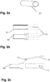
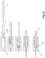
- FIGS. 2a-2f show an embodiment of a method for producing a supply hose with such a tip.
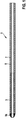
- Figure 1 schematically shows the distal end region of a catheter system 1 of a self-expanding stent 3.
- the stent 3 is preferably made of nitinol and in the delivery state shown compressed in a distal end section of a delivery tube 5, in which - also proximally abutting the proximal end of the stent -
- a flexible push tube 7 is housed as a sliding element for releasing the stent.
- the supply tube 5 is formed from an e-PTFE laminate, and a temporarily glued, compressed and curved chronically tapering tip region is formed in a distal end section 5a by impregnation with a stearic acid-based adhesive and thermocompression treatment in the manner described above.
- This tip area is relatively stiff when delivered.
- the stent 3 When the stent 3 is pushed forward by means of the push tube 7, it is stretched by the stent, and the adhesive matrix is broken up and the material composite is delaminated and reconfigured to a cylindrical to trumpet-shaped release state, which is also mechanically much softer than the initial state.
- the high sliding ability of the e-PTFE also makes it easier to push the stent forward and, after it has been fed in, to pull the delivery tube back out of the corresponding vessel.
- FIG. 2a shows a cut piece 51 of an e-PTFE tube, which as in Figure 2b shown with a suitable tool 10 (e.g. pliers) is expanded on one side.
- the expanded e-PTFE tube piece 52 is contacted with a cyanoacrylate adhesive by means of a suitable rod 11 and pushed onto the end of a feed tube 5 ( Figure 2c ) so that a feed tube tip preform as in Figure 2d arises.
- This preform made of e-PTFE tube piece 52 and feed tube 5 is immersed in a vessel 12 with a solution 13 containing stearic acid ( Figure 2e ), so that the e-PTFE tube piece 52 is coated with this solution.
- the combination of coated e-PTFE tube piece 52 and supply tube 5 is pushed into a heatable mold 8 with a suitable stamp 9 ( Figure 2f ).
- the combination of the e-PTFE tube piece 52 and the feed tube 5 is heated while moving up to above the melting temperature of the olefin matrix (in this exemplary embodiment to over 76 ° C.) and pressed together (compressed).
- a supply hose 5 according to the invention is thus formed with a distal end section 5a which is designed as a tip in the sense of the invention.
Landscapes
- Health & Medical Sciences (AREA)
- Life Sciences & Earth Sciences (AREA)
- Veterinary Medicine (AREA)
- Public Health (AREA)
- General Health & Medical Sciences (AREA)
- Animal Behavior & Ethology (AREA)
- Engineering & Computer Science (AREA)
- Biomedical Technology (AREA)
- Heart & Thoracic Surgery (AREA)
- Chemical & Material Sciences (AREA)
- Epidemiology (AREA)
- Child & Adolescent Psychology (AREA)
- Hematology (AREA)
- Chemical Kinetics & Catalysis (AREA)
- Anesthesiology (AREA)
- Pulmonology (AREA)
- Biophysics (AREA)
- Vascular Medicine (AREA)
- Transplantation (AREA)
- Cardiology (AREA)
- Oral & Maxillofacial Surgery (AREA)
- Molecular Biology (AREA)
- Medicinal Chemistry (AREA)
- Dispersion Chemistry (AREA)
- Materials For Medical Uses (AREA)
- Media Introduction/Drainage Providing Device (AREA)
Description
- Die Erfindung betrifft ein Kathetersystem mit funktionalem Element am distalen Ende, einem mit seinem distalen Ende das funktionale Element umgebenden Zuführschlauch und einem am proximalen Ende des funktionalen Elements anstoßenden Schiebeelement zum Vorschieben des funktionalen Elements aus dem Zuführschlauch, um die Funktion des funktionalen Elements im Körper zu bewirken. Der im Lieferzustand verjüngenden und beim Herauschieben des Gefäßdilators expandierbaren Spitzenabschnitt des Zuführschlaugs ist aus einem temporär verklebten, unter Dehnung delaminierenden e-PTFE-Laminat geformt, wobei das e-PTFE-Laminat mit einem Klebstoff verklebt ist, welcher als functionswesentlichen Bestandteil eine Fettsäure aufweist. Die Erfindung betrifft des Weiteren ein Verfahren zur Herstellung eines solchen Systems.
- Die Erfindung wird im Folgenden am Beispiel eines selbstexpandierenden Stents als funktionales Element beschrieben. Sie ist jedoch allgemein für Kathetersysteme geeignet, bei der ein funktionales Element von einem Zuführschlauch umgeben ist und mit Hilfe eines Schiebeelements, häufig als pusher bezeichnet, aus dem Zuführschlauch heraus geschoben wird. Als funktionale Elemente kommen hier beispielsweise bei mechanisch wirkenden Kathetersystemen Elemente in Frage, die dazu ausgebildet sind, Gewebeproben zu entnehmen, Gewebeablagerungen zu entfernen oder Gewebe zu penetrieren.
Im Rahmen dieser Anmeldung wird unter dem distalen Ende, z.B. des Kathetersystem, das Ende verstanden, welches vom Behandler entfernt liegt. Das proximale Ende des Kathetersystems ist entsprechend dem Behandler am nächsten.
Selbstexpandierende Stents, die ohne einen Ballonkatheter funktionieren, sind seit langen bekannt, und entsprechende Applikationssysteme sind im ständigen klinischen Einsatz. Im Hinblick auf die bevorzugt verwendeten Materialien zur Herstellung werden derartige Stents beispielsweise auch als "Nitinol-Stents" bezeichnet; sie werden unter anderem von der Anmelderin angeboten. - Es sind verschiedene Ausführungen von Kathetersystemen für selbstexpandierende Stents bekannt geworden, darunter Systeme ohne "inner lumen", die vorteilhafter Weise mit geringem Durchmesser realisierbar sind und eine Reduktion des Traumas beim Kathetereingriff ermöglichen und eine besonders hohe Flexibilität aufweisen. Bei solchen Systemen bildet der Stent selbst das Lumen für den Führungsdraht, und das distale Katheterende (Tip) muss mit dem Zuführschlauch verbunden bzw. als distaler Abschnitt desselben ausgebildet sein. Die Spitze wird über plastische Deformation geöffnet, wenn der Stent mittels des Schiebeelementes nach distal aus dem Zuführschlauch herausgeschoben wird. Die Spitze muss hinsichtlich ihrer mechanischen Eigenschaften sowohl den Anforderungen bei der Zuführung des Stents (Release) als auch beim Zurückziehen des Katheters genügen.
- Vereinfacht ausgedrückt, bestehen derartige Systeme nur aus dem Zuführschlauch, der den selbstexpandierenden Stent, das Schiebeelement und den Führungsdraht umgibt. Der selbstexpandierenden Stents wird durch den Zuführschlauch in seinem komprimierten ("gecrimpten") Zustand gehalten. Durch das Schiebeelement wird der Stent aus dem Zuführschlauch heraus geschoben und expandiert ("dilatiert") in das umgebende Blutgefäß, um dieses zu erweitern oder zu stützen. Derartige Systeme verzichten auf den sonst üblichen Innenschlauch oder Innenschaft, der das Führungsdrahtlumen bildet bzw. den Führungsdraht umgibt, und den selbstexpandierenden Stent trägt.
- Entsprechend haben solche Kathetersysteme der eingangs beschriebenen Art ohne Innenschaft den Vorteil, dass sie im Durchmesser reduziert werden können, wodurch in der Regel eine höhere Flexibilität erreicht wird und auf kleinere Hilfselemente (Einführhilfen und/oder Führungskatheter) gewechselt werden kann.
- Bei einem Kathetersystem der eingangs genannten Art ohne Innenschaft muss die distale Katheterspitze zwangsläufig am Zuführschlauch befestigt sein. Die Katheterspitze rundet den Zuführschlauch ab und gewährleistet, dass das Gewebe beim Einführen des Kathetersystems und beim Vorschub zur eigentlichen Stelle im Körper, an der das funktionelle Element seine Funktion ausüben soll, nicht traumatisiert oder verletzt wird. Entsprechend soll eine derartige Spitze bei der Verformung durch das Freisetzen des funktionellen Elements nicht derart plastisch verformt werden, dass sie nach erfolgter Verformung potentielle traumatisch wird oder den Rückzug des Kathetersystems aus dem Körper behindert. Eine ideale elastische Deformation der Katheterspitze ist anzustreben, so dass das funktionelle Element unter stetiger Reibung durch die elastische Rückstellkraft der Katheterspitze freigesetzt werden muss.
US 20050165352 A offenbart ferner ein Zuführsystem mit einem Stent und einer sich verjüngenden Spitze. - Der Erfindung liegt daher die Aufgabe zugrunde, ein Kathetersystem der genannten Art bereitzustellen, welches die speziellen Anforderungen an die mechanischen Eigenschaften der Spitze in den verschiedenen Phasen des Einsatzes des Systems in verbesserter Weise erfüllt. Des Weiteren soll ein Verfahren zur Herstellung eines solchen Kathetersystems angegeben werden.
- Diese Aufgabe wird in ihrem Vorrichtungsaspekt durch ein Kathetersystem mit den Merkmalen des Anspruchs 3 sowie durch einen Zuführschlauch mit den Merkmalen des Anspruchs 1 und in ihrem Verfahrensaspekt durch ein Verfahren mit den Merkmalen des Anspruchs 10 gelöst. Zweckmäßige Fortbildungen des Erfindungsgedankens sind Gegenstand der jeweiligen abhängigen Ansprüche.
- Die Erfindung geht von der Überlegung aus, dass bei einem Kathetersystem der genannten Art die Spitze in verschiedenen Einsatzphasen unterschiedliche geometrische Konfigurationen und mechanische Eigenschaften haben sollte: Im Lieferzustand sollte der Durchmesser des Systems (speziell des Zuführschlauches) sich zum distalen Ende hin verringern, es sollte also tatsächlich eine Art Spitze gebildet sein, welche zudem eine hinreichende Steifigkeit aufweist. In der Zuführphase sollte diese Spitze verformbar sein und idealerweise eine zweite geometrische Konfiguration annehmen, etwa zylindrisch oder trompetenförmig werden, und dann relativ weich sein und minimale Rückstellkräfte auf das frei zu setzende funktionelle Element ausüben. Um auch eine atraumatische Rückführung des Kathetersystems bzw. dessen Rückzug durch eventuelle Hilfssysteme nicht negativ zu beeinflussen, sollte sich auch das mechanische Verhalten des verformten Bereiches ändern. Die mechanischen Eigenschaften der nicht verformten Spitze sollen sich durch Zähigkeit und Biegsamkeit auszeichnen, während die verformte Spitze eine deutlich erhöhte Biegsamkeit und eine möglichst geringe Steifigkeit aufweisen soll. In beiden Zuständen muss die mechanische Integrität der Spitze gegeben bleiben. Die Oberfläche soll reibungsarm sein, um die bei Kontakt mit dem Körpergefäß dieses nicht zu reizen.
- Von diesen Überlegungen ausgehend, schließt die Erfindung den Gedanken ein, den distalen Endabschnitt des Systems für die Liefersituation in einer solchen Weise spitzenartig und relativ steif auszubilden, dass bei der Einleitung und während der Zuführ- bzw. der Freisetzung des funktionellen Elements, insbesondere der Expansionsphase des Stents, in Folge einer vorbestimmten Materialumwandlung sowohl die Spitzen-Konfiguration als auch die mechanische Steifigkeit weitgehend aufgehoben werden. Des Weiteren schließt die Erfindung die Überlegung ein, dies mittels eines e-PTFE-Schichtmaterials zu erreichen, welches als solches bekannt ist und auch im medizinischen Bereich bereits eingesetzt wird.
- E-PTFE ist als sehr weiches, elastisches, reibungsarmes und hydrophobes Material bekannt. Es lässt sich durch die thermische Verfahrenstechnik der Herstellung sehr gut auf elastische, plastische wie auf Festigkeitsanforderungen einstellen. Die bemerkenswerte Flexibilität im Vergleich zur Festigkeit beruht auf der Mikrostruktur von e-PTFE, die während Sinter und Verzugsprozessen im Herstellungsprozess entsteht.
- Diese Mikrostruktur ermöglicht - im Gegensatz zu herkömmlichen PTFE-Bauteilen - eine hervorragende Klebbarkeit, wenn die Mikrostruktur des e-PTFE's durch den Klebstoff penetriert werden kann. Hiermit lässt sich leicht eine einfach auszuführende und zuverlässige Verbindung eines e-PTFE Schlauches zu einem verbindenden Schlauch, wie z. B. einem "Releaseschlauch" bzw. Zuführschlauch eines Katheters, herstellen.
- Ein wesentlicher Aspekt der Erfindung besteht darin, dass der distale Endabschnitt des Zuführschlauches aus einem derart temporär verklebten e-PTFE-Laminat in einer Spitzen-Konfiguration besteht, dass der verklebte und durch die Verklebung sowohl in seine Form gebrachte als auch mechanische versteifte Verbund sich in der Zuführphase (wo er einer Dehnung unterliegt) mindestens teilweise delaminiert. Durch diese Delaminierung geht die vorgeprägte geometrische Form mindestens graduell verloren, d. h. die ursprüngliche Spitze weitet sich auf, und es bildet sich die weiter oben erwähnte wünschenswerte Zylinder-oder Trompeteform. Des Weiteren geht die mechanische Steifigkeit mindestens teilweise verloren, so dass die erwünschte Weichheit und Reduktion von auf den Stent einwirkenden Rückstellkräften eintritt.
- In einer Ausführung der Erfindung ist der Spitzenabschnitt des Zuführschlauchs kegelstumpfförmig oder mit einem abgerundeten distalen Ende formgepresst. Hierbei kann das distale Ende sphärisch geformt sein, und eine konische Spitze kann speziell einen sphärischen Abschluss haben.
- Es ist erfindungsgemäß vorgesehen, dass das e-PTFE-Laminat mit einem Klebstoff verklebt ist, welcher als funktionswesentlichen Bestandteil eine Fettsäure, insbesondere Stearinsäure, aufweist. Hierbei ist in Ausgestaltungen vorgesehen, dass der Klebstoff einen Ölsäurezusatz oder festigkeitserhöhenden polymeren Zusätze wie Polyvinylpyrrolidon oder ähnlichem aufweist. Die Kombination von Stearinsäure mit Ölsäure ist hierbei nur beispielhaft für sinnvolle Kombinationen von Klebstoffkomponenten für die temporäre Verklebung zu verstehen; außerdem können andere in der Fettsäurematrix lösbare Polymere außer PVP zur Eigenschafts-Verbesserung der funktionswesentlichen Fettsäure beitragen.
- In einer weiteren Ausführung der Erfindung umfasst das Kathetersystem einen Stent, der derart ausgebildet ist, dass er unter Schubbelastung, beim Vorschieben aus dem Zuführschlauch, auf Block geht. Unter auf "Block gehen" wird im Rahmen dieser Anmeldung verstanden, dass der Stent derart ausgestaltet ist, dass sich einzelne Stentsegmente nicht überlappen oder über einander geschoben werden bzw. gegeneinander verkanten. Unter der Vielzahl bekannter und großteils auch kommerziell verfügbarer Stent-Konstruktionen findet der Fachmann solche, die diese Anforderung erfüllen und hierdurch vorteilhaft mit der vorgeschlagenen Gestaltung des distalen Endbereiches des Systems zusammenwirken können.
- In sinnvollen geometrischen Konfigurationen ist vorgesehen, dass die Länge des Spitzenabschnitts im Bereich des 0,3-fachen bis 5-fachen, insbesondere des 0,6-fachen bis 2-fachen, Außendurchmessers des Zuführschlauchs liegt. Es ist allerdings zu verstehen, dass auch außerhalb dieser Relationen liegende Konfigurationen, bei denen die erwähnte temporäre, durch Dehnungs-Beanspruchung gezielt zerstörbare Verklebung des Endabschnittes vorliegt, zur Erfindung gehören.
- In einer weiteren Ausführung ist der Spitzenabschnitt einstückig mit dem Zuführschlauch gebildet. Diese Ausführung ist sowohl technologisch besonders einfach zu realisieren als auch mechanisch stark belastbar. Grundsätzlich ist aber auch ein Verbund zwischen einer mit temporärer Verklebung versehenen Spitze aus einem ersten Material und einem Zuführschlauch aus einem zweiten Material als im Bereich der Erfindung liegend anzusehen. Bei einer solchen alternativen Ausführung lassen sich die Materialien für den langen Zuführschlauch und den kurzen Endabschnitt differenziert auswählen und an die jeweiligen Anforderungen anpassen.
- Zur Herstellung des vorgeschlagenen Kathetersystems sind im Wesentlichen die herkömmlichen Verfahren geeignet, wobei die Realisierung der temporären und durch Dehnung aufhebbaren Verklebung des Zuführschlauch-Endabschnittes eine besondere Ausgestaltung erfordert. Abhängig von der Materialwahl des Klebstoffs und davon, ob der Endabschnitt einstückig mit dem übrigen Zuführschlauch gebildet ist oder nicht, ergibt sich eine Vielzahl von grundsätzlich möglichen Verfahrensvarianten.
- Speziell für den Einsatz von Fettsäuren als funktionswesentlicher Bestandteil der Klebeverbindung wird eine Verfahrensführung vorgeschlagen, bei der ein schlauchförmig vorkonfiguriertes e-PTFE-Laminat bzw. e-PTFE Bauteil (vielschichtig aufgebaut) mit einer die Fettsäure (speziell Stearinsäure) enthaltenden Lösung bei erhöhter Temperatur getränkt und dann getrocknet wird. Später wird die gewünschte geometrische Form der Spitze durch Formpressen, ebenfalls bei erhöhter Temperatur, ausgebildet und zugleich eine Stauchung und somit mechanische Verdichtung des Materialsgefüges bewirkt. Nach dem Abkühlen liegt ein Spitzenabschnitt mit den für die Liefersituation des Applikationssystems gewünschten Eigenschaften vor.
- In Ausgestaltungen dieses Verfahrens liegt die erste erhöhte Verfahrenstemperatur im Bereich zwischen 60°C und 90°C, insbesondere zwischen 70°C und 85°C und spezieller bei 80°C und die zweite Verfahrenstemperatur oberhalb des Schmelzpunktes der Fettsäure, insbesondere im Bereich zwischen 70°C und 90°C und spezieller im Bereich zwischen 75°C und 85°C.
- Ein spezieller Vorteil dieser Applikationsmethode beruht auf der Beobachtung, dass aus Lösung getrocknet vorzugsweise ein kristalliner Niederschlag der Stearinsäure erhalten wird. Wird das e-PTFE mit dieser Lösung getränkt, bleibt es zunächst noch relativ flexibel. Unter Druck und Stauchung lässt sich solch ein getränkter Schlauch in die Form einer konischen Spitze komprimieren. Ab einer Temperatur beim Schmelzpunkt (69°C) wird die Stearinsäure aufgeschmolzen und bildet in Verbindung mit dem e-PTFE im Prinzip einen "Faserverbundwerkstoff", der zumindest sehr druckfest und reibungsarm ist. Unter Zugbelastung erfolgt dann aber - gegeben durch die geringe Festigkeit der Matrix - eine Delamination der Matrix, und je nach Belastung wird der "e-PTFE" Schlauch wieder freigesetzt. Dieser erhält annähernd seine Flexibilität zurück.
- Vorteile und Zweckmäßigkeiten der Erfindung ergeben sich aus der nachfolgenden Beschreibung anhand des in
Figur 1 dargestellten Ausführungsbeispiels der Erfindung. DieFiguren 2a-2f zeigen ein Ausführungsbeispiel eines Verfahrens zur Herstellung eines Zuführschlauches mit einer derartigen Spitze. - Es zeigen
- Fig. 1
- ein erfindungsgemäßes Ausführungsbeispiel eines Kathetersystem zur Implantation eines selbstexpandierenden Stents und
- Fig. 2a-f
- ein Ausführungsbeispiel zur Herstellung und Befestigung einer Spitze an einen Zuführschlauch gemäß der Erfindung
-
Figur 1 zeigt schematisch den distalen Endbereich eines Kathetersystems 1 eines selbstexpandierenden Stents 3. Der Stent 3 ist bevorzugt aus Nitinol und in dem in der Figur gezeigten Lieferzustand komprimiert in einem distalen Endabschnitt eines Zuführschlauches 5 untergebracht, in dem außerdem - proximal an das proximale Ende des Stents anstoßend - ein flexibles Schubrohr 7 als Schiebeelement zum Freisetzen des Stents untergebracht ist. - Der Zuführschlauch 5 ist aus einem e-PTFE-Laminat gebildet, und in einem distalen Endabschnitt 5a ist durch Tränkung mit einem Klebstoff auf Stearinsäure-Basis und Thermokompressions-Behandlung in der oben beschriebenen Weise ein temporär verklebter, verdichteter und gekrümmt chronisch zulaufender Spitzenbereich gebildet.
- Dieser Spitzenbereich ist im Lieferzustand relativ steif. Er wird beim Vorschieben des Stents 3 mittels des Schubrohres 7 durch den Stent auf Dehnung beansprucht, und die Klebstoffmatrix wird aufgebrochen und der Materialverbund insofern delaminiert und in einen zylinder- bis trompetenförmigen Release-Zustand umkonfiguriert, der gegenüber dem Ausgangszustand auch mechanisch wesentlich weicher ist. Die hohe Gleitfähigkeit des e-PTFE erleichtert zusätzlich das Vorschieben des Stents, wie auch, nach dessen Zuführung, das Zurückziehen des Zuführschlauches aus dem entsprechenden Gefäß.
- In den
Figuren 2a bis 2f wird ein Ausführungsbeispiel der Herstellung eines erfindungsgemäßen Zuführschlauches für ein erfindungsgemäßes Kathetersystem gezeigt.Figur 2a zeigt ein zugeschnittenes Stück 51 eines e-PTFE Schlauches, welcher wie inFigur 2b gezeigt mit einem geeigneten Werkzeug 10 (beispielsweise eine Zange) an einer Seite aufgeweitet wird. Das aufgeweitete e-PTFE Schlauchstück 52 wird mittels eines geeigneten Stabes 11 mit einem Cyanacrylat-Kleber kontaktiert und auf das Ende eines Zuführschlauches 5 geschoben (Figur 2c ), so dass eine Zuführschlauch-Spitze Vorform wie inFigur 2d entsteht. Diese Vorform aus e-PTFE Schlauchstück 52 und Zuführschlauch 5 wird in ein Gefäß 12 mit einer Stearinsäure enthaltenden Lösung 13 getaucht (Figur 2e ), so dass das e-PTFE Schlauchstück 52 mit dieser Lösung beschichtet ist. Die Kombination aus beschichteten e-PTFE Schlauchstück 52 und Zuführschlauch 5 wird mit einem geeigneten Stempel 9 in eine erwärmbare Form 8 geschoben (Figur 2f ). In der Form 8 wird die Kombination aus e-PTFE Schlauchstück 52 und Zuführschlauch 5 unter Bewegung bis oberhalb der Schmelztemperatur der Olefinmatrix erwärmt (in diesem Ausführungsbeispiel auf über 76°C) und zusammen gepresst (verdichtet). Nach anschließender Abkühlung entsteht derart ein erfindungsgemäßer Zuführschlauch 5 mit einem distalen Endabschnitt 5a das als Spitze im Sinne der Erfindung ausgebildet ist.
Claims (11)
- Zuführschlauch für ein Kathetersystem mit einem sich im Lieferzustand verjüngenden und beim Herausschieben des Gefäßdilators expandierbaren Spitzenabschnitt, welcher aus einem temporär verklebten, unter Dehnung delaminierenden e-PTFE-Laminat geformt ist, wobei das e-PTFE-Laminat mit einem Klebstoff verklebt ist, welcher als funktionswesentlichen Bestandteil eine Fettsäure aufweist.
- Zuführschlauch nach Anspruch 1, wobei der Spitzenabschnitt einstückig mit dem Zuführschlauch gebildet ist.
- Kathetersystem mit funktionalen Element am distalen Ende, einem mit seinem distalen Ende das funktionale Element umgebenden Zuführschlauch nach einem der vorhergehenden Ansprüche und einem am proximalen Ende des funktionalen Elements anstoßenden Schiebeelement zum Vorschieben des funktionalen Elements aus dem Zuführschlauch.
- Kathetersystem nach Anspruch 3, dadurch gekennzeichnet, dass das funktionale Element ein selbst-expandierender Stent ist.
- Kathetersystem nach Anspruch 3 oder 4, dadurch gekennzeichnet, dass der Spitzenabschnitt des Zuführschlauchs kegelstumpfförmig oder mit einem abgerundeten distalen Ende formgepresst ist.
- Kathetersystem nach einem der Ansprüche 3 bis 5, dadurch gekennzeichnet, dass der Klebstoff Stearinsäure aufweist.
- Kathetersystem nach Anspruch 6, wobei der Klebstoff einen Ölsaure- oder festigkeitserhöhenden polymeren Zusatz von Polyvinylpyrrolidon oder ähnlichem aufweist.
- Kathetersystem nach einem der vorangehenden Ansprüche, wobei die Länge des Spitzenabschnitts im Bereich des 0,3-fachen bis 5-fachen, insbesondere des 0,6-fachen bis 2-fachen, Außendurchmessers des Zuführschlauchs liegt.
- Kathetersystem nach einem der vorangehenden Ansprüche, wobei der Spitzenabschnitt einstückig mit dem Zuführschlauch gebildet ist.
- Verfahren zur Herstellung eines Kathetersystems nach einem der Ansprüche 3 - 9, wobei der Spitzenabschnitt des Zuführschlauchs aus einem schlauchförmig vorkonfigurierten e-PTFE-Laminat durch Tränken desselben mit einer Fettsäure, insbesondere Stearinsäure, enthaltenden, insbesondere alkoholischen, Lösung bei einer ersten gegenüber Raumtemperatur erhöhten Verfahrenstemperatur und späteres Formpressen des getränkten Spitzenabschnitts bei einer zweiten erhöhten Verfahrenstemperatur gebildet wird.
- Verfahren nach Anspruch 10, wobei die erste erhöhte Verfahrenstemperatur im Bereich zwischen 60°C und 90°C, insbesondere zwischen 70°C und 85°C und spezieller bei 80°C und die zweite Verfahrenstemperatur oberhalb des Schmelzpunktes der Fettsäure, insbesondere im Bereich zwischen 70°C und 90°C und spezieller im Bereich zwischen 75°C und 85°C, liegt.
Applications Claiming Priority (2)
| Application Number | Priority Date | Filing Date | Title |
|---|---|---|---|
| US201462050211P | 2014-09-15 | 2014-09-15 | |
| US201462050212P | 2014-09-15 | 2014-09-15 |
Publications (3)
| Publication Number | Publication Date |
|---|---|
| EP3000446A2 EP3000446A2 (de) | 2016-03-30 |
| EP3000446A3 EP3000446A3 (de) | 2016-04-20 |
| EP3000446B1 true EP3000446B1 (de) | 2020-02-12 |
Family
ID=53488242
Family Applications (2)
| Application Number | Title | Priority Date | Filing Date |
|---|---|---|---|
| EP15173651.9A Active EP3000446B1 (de) | 2014-09-15 | 2015-06-24 | Kathetersystem und verfahren zur herstellung eines solchen |
| EP15173650.1A Active EP2995339B1 (de) | 2014-09-15 | 2015-06-24 | Ballonkatheter |
Family Applications After (1)
| Application Number | Title | Priority Date | Filing Date |
|---|---|---|---|
| EP15173650.1A Active EP2995339B1 (de) | 2014-09-15 | 2015-06-24 | Ballonkatheter |
Country Status (2)
| Country | Link |
|---|---|
| US (2) | US20160074632A1 (de) |
| EP (2) | EP3000446B1 (de) |
Families Citing this family (1)
| Publication number | Priority date | Publication date | Assignee | Title |
|---|---|---|---|---|
| EP4282385A3 (de) * | 2016-10-05 | 2024-02-28 | Terumo Corporation | Ballonkatheter |
Family Cites Families (21)
| Publication number | Priority date | Publication date | Assignee | Title |
|---|---|---|---|---|
| US20040210236A1 (en) * | 2001-07-09 | 2004-10-21 | Mats Allers | Flow path control catheter with funnel-shaped expandable structure at proximal part and tubular-shaped structure at distal part and perfusion system with such a catheter |
| JP4351832B2 (ja) * | 2002-08-05 | 2009-10-28 | テルモ株式会社 | バルーンカテーテル |
| US7468070B2 (en) * | 2004-01-23 | 2008-12-23 | Boston Scientific Scimed, Inc. | Stent delivery catheter |
| US8308789B2 (en) * | 2004-07-16 | 2012-11-13 | W. L. Gore & Associates, Inc. | Deployment system for intraluminal devices |
| US7892592B1 (en) * | 2004-11-30 | 2011-02-22 | Advanced Cardiovascular Systems, Inc. | Coating abluminal surfaces of stents and other implantable medical devices |
| US7632296B2 (en) * | 2005-03-03 | 2009-12-15 | Boston Scientific Scimed, Inc. | Rolling membrane with hydraulic recapture means for self expanding stent |
| US20080045896A1 (en) * | 2006-08-17 | 2008-02-21 | Abott Laboratories | Catheter having intermediate position markers |
| US8153181B2 (en) * | 2006-11-14 | 2012-04-10 | Boston Scientific Scimed, Inc. | Medical devices and related methods |
| US8690823B2 (en) * | 2007-07-13 | 2014-04-08 | Abbott Cardiovascular Systems Inc. | Drug coated balloon catheter |
| US20110137245A1 (en) * | 2007-09-12 | 2011-06-09 | Cook Medical Technologies Llc | Balloon catheter with embedded rod |
| WO2010120620A1 (en) * | 2009-04-13 | 2010-10-21 | Cook Incorporated | Coated balloon catheter |
| US9180274B2 (en) * | 2010-09-09 | 2015-11-10 | W. L. G ore & Associates, Inc | Indwelling luminal devices |
| US9327101B2 (en) * | 2010-09-17 | 2016-05-03 | Abbott Cardiovascular Systems Inc. | Length and diameter adjustable balloon catheter |
| EP2450010B1 (de) * | 2010-11-09 | 2013-11-20 | Biotronik AG | Ballon-Katheter, insbesondere zum Ausbringen von Medikamenten oder Stents im Bereich einer Stenose |
| EP2709711B8 (de) * | 2011-05-18 | 2017-03-22 | Vatrix Medical, Inc. | Beschichtete ballons zur blutgefässstabilisierung |
| CN104245037A (zh) * | 2012-03-09 | 2014-12-24 | 明讯科技有限公司 | 具有用于精确识别工作表面的不透射线标识物的医用球囊 |
| WO2014102611A2 (en) * | 2012-12-31 | 2014-07-03 | Clearstream Technologies Limited | Radiopaque balloon catheter and guidewire to facilitate alignment |
| CN105307716B (zh) * | 2013-05-03 | 2021-09-14 | C·R·巴德公司 | 可剥离保护套 |
| US10130662B2 (en) * | 2013-10-22 | 2018-11-20 | Tulip Endovascular Innovation Limited | Therapeutic agent delivery system and method for arteries |
| US20150190618A1 (en) * | 2014-01-09 | 2015-07-09 | Medtronic Vascular, Inc. | Balloon Catheter With Elastomeric Sheath and Methods |
| US10569063B2 (en) * | 2014-10-03 | 2020-02-25 | W. L. Gore & Associates, Inc. | Removable covers for drug eluting medical devices |
-
2015
- 2015-06-24 EP EP15173651.9A patent/EP3000446B1/de active Active
- 2015-06-24 EP EP15173650.1A patent/EP2995339B1/de active Active
- 2015-08-12 US US14/824,257 patent/US20160074632A1/en not_active Abandoned
- 2015-08-17 US US14/827,871 patent/US20160074187A1/en not_active Abandoned
Non-Patent Citations (1)
| Title |
|---|
| None * |
Also Published As
| Publication number | Publication date |
|---|---|
| EP3000446A2 (de) | 2016-03-30 |
| EP2995339B1 (de) | 2020-01-08 |
| US20160074632A1 (en) | 2016-03-17 |
| EP3000446A3 (de) | 2016-04-20 |
| US20160074187A1 (en) | 2016-03-17 |
| EP2995339A2 (de) | 2016-03-16 |
| EP2995339A3 (de) | 2016-08-31 |
Similar Documents
| Publication | Publication Date | Title |
|---|---|---|
| EP0592726B1 (de) | Katheter mit einer Gefässstütze | |
| EP0554579B1 (de) | Katheter mit einer Gefässstütze | |
| EP3265038B1 (de) | Implantateinführsystem | |
| DE19828415B4 (de) | Stent für ein Endoskop und System zum Einführen dieses Stents | |
| EP1976466A1 (de) | Einführsystem für stents mit zug-druck-kinematik | |
| EP2710985A2 (de) | Implantat, System aus einem Implantat und einem Katheter sowie Verfahren zur Herstellung eines solchen Systems | |
| EP4009918B1 (de) | Implantat mit einer dreidimensionalen struktur | |
| EP3041439B9 (de) | Einführ- und ablösesystem für implantate | |
| EP2496152A2 (de) | Medizinische vorrichtung zum rekanalisieren von körperhohlräumen, set umfassend eine derartige vorrichtung und verfahren zur herstellung einer medizinischen vorrichtung | |
| EP2839815A1 (de) | Kathetersystem mit beweglicher Hülle | |
| WO2000074557A1 (de) | Intravasal implantierbare vorrichtung | |
| EP3100762B1 (de) | Diagnostisches medizinprodukt mit einer haftvermittelnden oberflächenstruktur | |
| EP3000446B1 (de) | Kathetersystem und verfahren zur herstellung eines solchen | |
| DE102011121964B4 (de) | Katheter mit steuerbarer Katheterspitze | |
| EP1529494B1 (de) | Instrument zur Behandlung von osteopathisch veränderten Bereichen von menschlichen oder tierischen Knochen | |
| EP2676642A1 (de) | Freigabevorrichtung zum Lösen eines medizinischen Implantats von einem Katheter | |
| DE102009060279B4 (de) | Vorrichtung zur Zufuhr eines medizinischen Implantats und Anordnung mit einer derartigen Vorrichtung | |
| DE102011054907A1 (de) | Transportdraht und Zufuhrsystem mit einem Transportdraht | |
| DE102021113558B4 (de) | Vorrichtung zum Zuführen eines Implantats in ein Körperhohlgefäß und Anordnung mit einer solchen Vorrichtung | |
| DE102013104565B3 (de) | Pusher-Baugruppe für ein Einführsystem für ein selbstexpandierendes Gefäßimplantat sowie ein entsprechendes Einführsystem | |
| EP2149356A2 (de) | Verfahren und Vorrichtung zum Beladen eines Stentapplikators | |
| DE60028918T2 (de) | Einführkatheter für eine selbstausdehnbare Prothese | |
| EP1283025A1 (de) | Ballonokklusionsvorrichtung | |
| EP1782745A1 (de) | Gewebemarker mit einem vorgeformten, distal geschlitzten Draht | |
| WO2025194199A1 (de) | Durchdringungselement |
Legal Events
| Date | Code | Title | Description |
|---|---|---|---|
| PUAL | Search report despatched |
Free format text: ORIGINAL CODE: 0009013 |
|
| PUAI | Public reference made under article 153(3) epc to a published international application that has entered the european phase |
Free format text: ORIGINAL CODE: 0009012 |
|
| AK | Designated contracting states |
Kind code of ref document: A2 Designated state(s): AL AT BE BG CH CY CZ DE DK EE ES FI FR GB GR HR HU IE IS IT LI LT LU LV MC MK MT NL NO PL PT RO RS SE SI SK SM TR |
|
| AX | Request for extension of the european patent |
Extension state: BA ME |
|
| AK | Designated contracting states |
Kind code of ref document: A3 Designated state(s): AL AT BE BG CH CY CZ DE DK EE ES FI FR GB GR HR HU IE IS IT LI LT LU LV MC MK MT NL NO PL PT RO RS SE SI SK SM TR |
|
| AX | Request for extension of the european patent |
Extension state: BA ME |
|
| RIC1 | Information provided on ipc code assigned before grant |
Ipc: A61M 25/10 20060101ALI20160316BHEP Ipc: A61F 2/966 20130101AFI20160316BHEP Ipc: A61L 29/04 20060101ALI20160316BHEP Ipc: A61M 25/06 20060101ALN20160316BHEP |
|
| 17P | Request for examination filed |
Effective date: 20160919 |
|
| RBV | Designated contracting states (corrected) |
Designated state(s): AL AT BE BG CH CY CZ DE DK EE ES FI FR GB GR HR HU IE IS IT LI LT LU LV MC MK MT NL NO PL PT RO RS SE SI SK SM TR |
|
| STAA | Information on the status of an ep patent application or granted ep patent |
Free format text: STATUS: EXAMINATION IS IN PROGRESS |
|
| 17Q | First examination report despatched |
Effective date: 20170823 |
|
| GRAP | Despatch of communication of intention to grant a patent |
Free format text: ORIGINAL CODE: EPIDOSNIGR1 |
|
| STAA | Information on the status of an ep patent application or granted ep patent |
Free format text: STATUS: GRANT OF PATENT IS INTENDED |
|
| RIC1 | Information provided on ipc code assigned before grant |
Ipc: A61M 25/06 20060101ALN20190815BHEP Ipc: A61L 29/04 20060101ALI20190815BHEP Ipc: A61F 2/966 20130101AFI20190815BHEP Ipc: A61M 25/10 20130101ALI20190815BHEP |
|
| INTG | Intention to grant announced |
Effective date: 20190913 |
|
| GRAS | Grant fee paid |
Free format text: ORIGINAL CODE: EPIDOSNIGR3 |
|
| GRAA | (expected) grant |
Free format text: ORIGINAL CODE: 0009210 |
|
| STAA | Information on the status of an ep patent application or granted ep patent |
Free format text: STATUS: THE PATENT HAS BEEN GRANTED |
|
| AK | Designated contracting states |
Kind code of ref document: B1 Designated state(s): AL AT BE BG CH CY CZ DE DK EE ES FI FR GB GR HR HU IE IS IT LI LT LU LV MC MK MT NL NO PL PT RO RS SE SI SK SM TR |
|
| REG | Reference to a national code |
Ref country code: GB Ref legal event code: FG4D Free format text: NOT ENGLISH |
|
| REG | Reference to a national code |
Ref country code: CH Ref legal event code: EP |
|
| REG | Reference to a national code |
Ref country code: AT Ref legal event code: REF Ref document number: 1231128 Country of ref document: AT Kind code of ref document: T Effective date: 20200215 |
|
| REG | Reference to a national code |
Ref country code: IE Ref legal event code: FG4D Free format text: LANGUAGE OF EP DOCUMENT: GERMAN |
|
| REG | Reference to a national code |
Ref country code: DE Ref legal event code: R096 Ref document number: 502015011674 Country of ref document: DE |
|
| REG | Reference to a national code |
Ref country code: NL Ref legal event code: FP |
|
| PG25 | Lapsed in a contracting state [announced via postgrant information from national office to epo] |
Ref country code: FI Free format text: LAPSE BECAUSE OF FAILURE TO SUBMIT A TRANSLATION OF THE DESCRIPTION OR TO PAY THE FEE WITHIN THE PRESCRIBED TIME-LIMIT Effective date: 20200212 Ref country code: RS Free format text: LAPSE BECAUSE OF FAILURE TO SUBMIT A TRANSLATION OF THE DESCRIPTION OR TO PAY THE FEE WITHIN THE PRESCRIBED TIME-LIMIT Effective date: 20200212 Ref country code: NO Free format text: LAPSE BECAUSE OF FAILURE TO SUBMIT A TRANSLATION OF THE DESCRIPTION OR TO PAY THE FEE WITHIN THE PRESCRIBED TIME-LIMIT Effective date: 20200512 |
|
| REG | Reference to a national code |
Ref country code: LT Ref legal event code: MG4D |
|
| PG25 | Lapsed in a contracting state [announced via postgrant information from national office to epo] |
Ref country code: GR Free format text: LAPSE BECAUSE OF FAILURE TO SUBMIT A TRANSLATION OF THE DESCRIPTION OR TO PAY THE FEE WITHIN THE PRESCRIBED TIME-LIMIT Effective date: 20200513 Ref country code: BG Free format text: LAPSE BECAUSE OF FAILURE TO SUBMIT A TRANSLATION OF THE DESCRIPTION OR TO PAY THE FEE WITHIN THE PRESCRIBED TIME-LIMIT Effective date: 20200512 Ref country code: HR Free format text: LAPSE BECAUSE OF FAILURE TO SUBMIT A TRANSLATION OF THE DESCRIPTION OR TO PAY THE FEE WITHIN THE PRESCRIBED TIME-LIMIT Effective date: 20200212 Ref country code: SE Free format text: LAPSE BECAUSE OF FAILURE TO SUBMIT A TRANSLATION OF THE DESCRIPTION OR TO PAY THE FEE WITHIN THE PRESCRIBED TIME-LIMIT Effective date: 20200212 Ref country code: LV Free format text: LAPSE BECAUSE OF FAILURE TO SUBMIT A TRANSLATION OF THE DESCRIPTION OR TO PAY THE FEE WITHIN THE PRESCRIBED TIME-LIMIT Effective date: 20200212 Ref country code: IS Free format text: LAPSE BECAUSE OF FAILURE TO SUBMIT A TRANSLATION OF THE DESCRIPTION OR TO PAY THE FEE WITHIN THE PRESCRIBED TIME-LIMIT Effective date: 20200612 |
|
| PG25 | Lapsed in a contracting state [announced via postgrant information from national office to epo] |
Ref country code: ES Free format text: LAPSE BECAUSE OF FAILURE TO SUBMIT A TRANSLATION OF THE DESCRIPTION OR TO PAY THE FEE WITHIN THE PRESCRIBED TIME-LIMIT Effective date: 20200212 Ref country code: CZ Free format text: LAPSE BECAUSE OF FAILURE TO SUBMIT A TRANSLATION OF THE DESCRIPTION OR TO PAY THE FEE WITHIN THE PRESCRIBED TIME-LIMIT Effective date: 20200212 Ref country code: RO Free format text: LAPSE BECAUSE OF FAILURE TO SUBMIT A TRANSLATION OF THE DESCRIPTION OR TO PAY THE FEE WITHIN THE PRESCRIBED TIME-LIMIT Effective date: 20200212 Ref country code: DK Free format text: LAPSE BECAUSE OF FAILURE TO SUBMIT A TRANSLATION OF THE DESCRIPTION OR TO PAY THE FEE WITHIN THE PRESCRIBED TIME-LIMIT Effective date: 20200212 Ref country code: EE Free format text: LAPSE BECAUSE OF FAILURE TO SUBMIT A TRANSLATION OF THE DESCRIPTION OR TO PAY THE FEE WITHIN THE PRESCRIBED TIME-LIMIT Effective date: 20200212 Ref country code: SM Free format text: LAPSE BECAUSE OF FAILURE TO SUBMIT A TRANSLATION OF THE DESCRIPTION OR TO PAY THE FEE WITHIN THE PRESCRIBED TIME-LIMIT Effective date: 20200212 Ref country code: LT Free format text: LAPSE BECAUSE OF FAILURE TO SUBMIT A TRANSLATION OF THE DESCRIPTION OR TO PAY THE FEE WITHIN THE PRESCRIBED TIME-LIMIT Effective date: 20200212 Ref country code: SK Free format text: LAPSE BECAUSE OF FAILURE TO SUBMIT A TRANSLATION OF THE DESCRIPTION OR TO PAY THE FEE WITHIN THE PRESCRIBED TIME-LIMIT Effective date: 20200212 Ref country code: PT Free format text: LAPSE BECAUSE OF FAILURE TO SUBMIT A TRANSLATION OF THE DESCRIPTION OR TO PAY THE FEE WITHIN THE PRESCRIBED TIME-LIMIT Effective date: 20200705 |
|
| REG | Reference to a national code |
Ref country code: DE Ref legal event code: R097 Ref document number: 502015011674 Country of ref document: DE |
|
| PLBE | No opposition filed within time limit |
Free format text: ORIGINAL CODE: 0009261 |
|
| STAA | Information on the status of an ep patent application or granted ep patent |
Free format text: STATUS: NO OPPOSITION FILED WITHIN TIME LIMIT |
|
| 26N | No opposition filed |
Effective date: 20201113 |
|
| PG25 | Lapsed in a contracting state [announced via postgrant information from national office to epo] |
Ref country code: IT Free format text: LAPSE BECAUSE OF FAILURE TO SUBMIT A TRANSLATION OF THE DESCRIPTION OR TO PAY THE FEE WITHIN THE PRESCRIBED TIME-LIMIT Effective date: 20200212 Ref country code: MC Free format text: LAPSE BECAUSE OF FAILURE TO SUBMIT A TRANSLATION OF THE DESCRIPTION OR TO PAY THE FEE WITHIN THE PRESCRIBED TIME-LIMIT Effective date: 20200212 |
|
| PG25 | Lapsed in a contracting state [announced via postgrant information from national office to epo] |
Ref country code: PL Free format text: LAPSE BECAUSE OF FAILURE TO SUBMIT A TRANSLATION OF THE DESCRIPTION OR TO PAY THE FEE WITHIN THE PRESCRIBED TIME-LIMIT Effective date: 20200212 Ref country code: SI Free format text: LAPSE BECAUSE OF FAILURE TO SUBMIT A TRANSLATION OF THE DESCRIPTION OR TO PAY THE FEE WITHIN THE PRESCRIBED TIME-LIMIT Effective date: 20200212 |
|
| GBPC | Gb: european patent ceased through non-payment of renewal fee |
Effective date: 20200624 |
|
| PG25 | Lapsed in a contracting state [announced via postgrant information from national office to epo] |
Ref country code: LU Free format text: LAPSE BECAUSE OF NON-PAYMENT OF DUE FEES Effective date: 20200624 |
|
| REG | Reference to a national code |
Ref country code: BE Ref legal event code: MM Effective date: 20200630 |
|
| PG25 | Lapsed in a contracting state [announced via postgrant information from national office to epo] |
Ref country code: GB Free format text: LAPSE BECAUSE OF NON-PAYMENT OF DUE FEES Effective date: 20200624 |
|
| PG25 | Lapsed in a contracting state [announced via postgrant information from national office to epo] |
Ref country code: BE Free format text: LAPSE BECAUSE OF NON-PAYMENT OF DUE FEES Effective date: 20200630 |
|
| PGFP | Annual fee paid to national office [announced via postgrant information from national office to epo] |
Ref country code: DE Payment date: 20210625 Year of fee payment: 7 Ref country code: FR Payment date: 20210622 Year of fee payment: 7 Ref country code: NL Payment date: 20210621 Year of fee payment: 7 |
|
| REG | Reference to a national code |
Ref country code: AT Ref legal event code: MM01 Ref document number: 1231128 Country of ref document: AT Kind code of ref document: T Effective date: 20200624 |
|
| PGFP | Annual fee paid to national office [announced via postgrant information from national office to epo] |
Ref country code: CH Payment date: 20210623 Year of fee payment: 7 Ref country code: IE Payment date: 20210622 Year of fee payment: 7 |
|
| PG25 | Lapsed in a contracting state [announced via postgrant information from national office to epo] |
Ref country code: AT Free format text: LAPSE BECAUSE OF NON-PAYMENT OF DUE FEES Effective date: 20200624 |
|
| PG25 | Lapsed in a contracting state [announced via postgrant information from national office to epo] |
Ref country code: TR Free format text: LAPSE BECAUSE OF FAILURE TO SUBMIT A TRANSLATION OF THE DESCRIPTION OR TO PAY THE FEE WITHIN THE PRESCRIBED TIME-LIMIT Effective date: 20200212 Ref country code: MT Free format text: LAPSE BECAUSE OF FAILURE TO SUBMIT A TRANSLATION OF THE DESCRIPTION OR TO PAY THE FEE WITHIN THE PRESCRIBED TIME-LIMIT Effective date: 20200212 Ref country code: CY Free format text: LAPSE BECAUSE OF FAILURE TO SUBMIT A TRANSLATION OF THE DESCRIPTION OR TO PAY THE FEE WITHIN THE PRESCRIBED TIME-LIMIT Effective date: 20200212 |
|
| PG25 | Lapsed in a contracting state [announced via postgrant information from national office to epo] |
Ref country code: MK Free format text: LAPSE BECAUSE OF FAILURE TO SUBMIT A TRANSLATION OF THE DESCRIPTION OR TO PAY THE FEE WITHIN THE PRESCRIBED TIME-LIMIT Effective date: 20200212 Ref country code: AL Free format text: LAPSE BECAUSE OF FAILURE TO SUBMIT A TRANSLATION OF THE DESCRIPTION OR TO PAY THE FEE WITHIN THE PRESCRIBED TIME-LIMIT Effective date: 20200212 |
|
| REG | Reference to a national code |
Ref country code: DE Ref legal event code: R119 Ref document number: 502015011674 Country of ref document: DE |
|
| REG | Reference to a national code |
Ref country code: CH Ref legal event code: PL |
|
| REG | Reference to a national code |
Ref country code: NL Ref legal event code: MM Effective date: 20220701 |
|
| PG25 | Lapsed in a contracting state [announced via postgrant information from national office to epo] |
Ref country code: NL Free format text: LAPSE BECAUSE OF NON-PAYMENT OF DUE FEES Effective date: 20220701 |
|
| PG25 | Lapsed in a contracting state [announced via postgrant information from national office to epo] |
Ref country code: LI Free format text: LAPSE BECAUSE OF NON-PAYMENT OF DUE FEES Effective date: 20220630 Ref country code: IE Free format text: LAPSE BECAUSE OF NON-PAYMENT OF DUE FEES Effective date: 20220624 Ref country code: FR Free format text: LAPSE BECAUSE OF NON-PAYMENT OF DUE FEES Effective date: 20220630 Ref country code: CH Free format text: LAPSE BECAUSE OF NON-PAYMENT OF DUE FEES Effective date: 20220630 |
|
| PG25 | Lapsed in a contracting state [announced via postgrant information from national office to epo] |
Ref country code: DE Free format text: LAPSE BECAUSE OF NON-PAYMENT OF DUE FEES Effective date: 20230103 |