EP3000428A2 - Zahnimplantat - Google Patents
Zahnimplantat Download PDFInfo
- Publication number
- EP3000428A2 EP3000428A2 EP15183400.9A EP15183400A EP3000428A2 EP 3000428 A2 EP3000428 A2 EP 3000428A2 EP 15183400 A EP15183400 A EP 15183400A EP 3000428 A2 EP3000428 A2 EP 3000428A2
- Authority
- EP
- European Patent Office
- Prior art keywords
- dental implant
- head portion
- thread
- body portion
- trench
- Prior art date
- Legal status (The legal status is an assumption and is not a legal conclusion. Google has not performed a legal analysis and makes no representation as to the accuracy of the status listed.)
- Withdrawn
Links
- 239000004053 dental implant Substances 0.000 title claims abstract description 201
- 238000005553 drilling Methods 0.000 claims abstract description 77
- 230000001186 cumulative effect Effects 0.000 claims abstract description 23
- 210000000988 bone and bone Anatomy 0.000 description 89
- 210000001847 jaw Anatomy 0.000 description 62
- 238000001356 surgical procedure Methods 0.000 description 16
- 239000000463 material Substances 0.000 description 12
- 239000012528 membrane Substances 0.000 description 12
- 238000000034 method Methods 0.000 description 12
- 239000011295 pitch Substances 0.000 description 11
- 210000000887 face Anatomy 0.000 description 9
- 238000010586 diagram Methods 0.000 description 7
- 238000002513 implantation Methods 0.000 description 7
- 208000014674 injury Diseases 0.000 description 7
- 235000013305 food Nutrition 0.000 description 6
- 239000007943 implant Substances 0.000 description 6
- 230000001154 acute effect Effects 0.000 description 5
- 230000006378 damage Effects 0.000 description 5
- 208000001132 Osteoporosis Diseases 0.000 description 4
- 230000008901 benefit Effects 0.000 description 4
- 230000000694 effects Effects 0.000 description 4
- 230000008733 trauma Effects 0.000 description 4
- 208000027418 Wounds and injury Diseases 0.000 description 3
- 230000035876 healing Effects 0.000 description 3
- 210000004086 maxillary sinus Anatomy 0.000 description 3
- 210000000256 facial nerve Anatomy 0.000 description 2
- 238000009434 installation Methods 0.000 description 2
- 230000010354 integration Effects 0.000 description 2
- 210000002050 maxilla Anatomy 0.000 description 2
- 230000029663 wound healing Effects 0.000 description 2
- RTAQQCXQSZGOHL-UHFFFAOYSA-N Titanium Chemical compound [Ti] RTAQQCXQSZGOHL-UHFFFAOYSA-N 0.000 description 1
- QCWXUUIWCKQGHC-UHFFFAOYSA-N Zirconium Chemical compound [Zr] QCWXUUIWCKQGHC-UHFFFAOYSA-N 0.000 description 1
- 230000003416 augmentation Effects 0.000 description 1
- 230000003796 beauty Effects 0.000 description 1
- 230000037182 bone density Effects 0.000 description 1
- 229940036811 bone meal Drugs 0.000 description 1
- 239000002374 bone meal Substances 0.000 description 1
- 239000000316 bone substitute Substances 0.000 description 1
- 230000001055 chewing effect Effects 0.000 description 1
- 230000001066 destructive effect Effects 0.000 description 1
- 238000005516 engineering process Methods 0.000 description 1
- 230000003203 everyday effect Effects 0.000 description 1
- 238000004299 exfoliation Methods 0.000 description 1
- 239000012634 fragment Substances 0.000 description 1
- 210000004195 gingiva Anatomy 0.000 description 1
- 210000003128 head Anatomy 0.000 description 1
- 210000004373 mandible Anatomy 0.000 description 1
- 230000002035 prolonged effect Effects 0.000 description 1
- 238000010079 rubber tapping Methods 0.000 description 1
- 230000002459 sustained effect Effects 0.000 description 1
- 229910052719 titanium Inorganic materials 0.000 description 1
- 239000010936 titanium Substances 0.000 description 1
- 229910052726 zirconium Inorganic materials 0.000 description 1
Images


Classifications
-
- A—HUMAN NECESSITIES
- A61—MEDICAL OR VETERINARY SCIENCE; HYGIENE
- A61C—DENTISTRY; APPARATUS OR METHODS FOR ORAL OR DENTAL HYGIENE
- A61C8/00—Means to be fixed to the jaw-bone for consolidating natural teeth or for fixing dental prostheses thereon; Dental implants; Implanting tools
- A61C8/0018—Means to be fixed to the jaw-bone for consolidating natural teeth or for fixing dental prostheses thereon; Dental implants; Implanting tools characterised by the shape
- A61C8/0022—Self-screwing
- A61C8/0025—Self-screwing with multiple threads
-
- A—HUMAN NECESSITIES
- A61—MEDICAL OR VETERINARY SCIENCE; HYGIENE
- A61C—DENTISTRY; APPARATUS OR METHODS FOR ORAL OR DENTAL HYGIENE
- A61C8/00—Means to be fixed to the jaw-bone for consolidating natural teeth or for fixing dental prostheses thereon; Dental implants; Implanting tools
- A61C8/0018—Means to be fixed to the jaw-bone for consolidating natural teeth or for fixing dental prostheses thereon; Dental implants; Implanting tools characterised by the shape
- A61C8/0022—Self-screwing
- A61C8/0024—Self-screwing with self-boring cutting edge
-
- A—HUMAN NECESSITIES
- A61—MEDICAL OR VETERINARY SCIENCE; HYGIENE
- A61C—DENTISTRY; APPARATUS OR METHODS FOR ORAL OR DENTAL HYGIENE
- A61C8/00—Means to be fixed to the jaw-bone for consolidating natural teeth or for fixing dental prostheses thereon; Dental implants; Implanting tools
- A61C8/0089—Implanting tools or instruments
- A61C8/0092—Implanting tools or instruments for sinus lifting
Definitions
- the present invention is related to a dental implant.
- the present invention relates to a dental implant which is a surgical component used in dental restoration surgery.
- dental restoration needs to remove tooth first. After three months, injuries of the removed site are healed over, it needs surgery again to have sinus lift, so that filling bone graft materials (such as bone substitute or bone meal) is hence achieved; then a hole on the upper jaw (maxilla) is drilled for filling the bone graft materials. After the bone graft materials had been filled, it needs to wait for further three to six months for healing; afterward, the dental implant therefore can be stably placed in the drilled hole of the upper jaw. Finally, after three to six months, a dental crown can be positioned on the dental implant to finish the dental restoration. In general, the period of traditional tooth restoration need to spend approximately one and half year.
- Taiwan Patent Application No. 095140364 Fe-In-One Fast Dental Implantation Method Having Beauty Effect
- Taiwan Patent Application No. 095140361 Increased Sinus Implant Surgery Instruments
- the kernel of those methods is only required one medical surgery to finish five procedures, including tooth revmoval, preoperative sinus lifting, bone grafting, implant placing, and dental crown installation. After three to four months, the artificial tooth can be attached.
- the aforementioned dental implantation treatment only takes half year, and the dental patient can use the new implanting artificial tooth to eat.
- the aforementioned dental restoration is less invasive with higher success rate. Those are practicability that not only the number of times of surgery can be reduced for patient, but also the healing period is shortened.
- the aforementioned fast dental implantation needs to drill a pilot hole by dentist, by using a dental drill engine (i.e. dental hand piece), for dental restoration.
- a dental drill engine i.e. dental hand piece
- the pilot hole needs to be gradually expanded by several different diameters of drills for several times. As a result, the duration of dental surgery is prolonged and dental trauma is expanded and deepened, so that the patient endures longer pain and their injuries are difficult to be healed.
- the sinus membrane may be drilled through if the upper jaw (maxillary sinus) is drilled too deep, and the facial nerve may be hurt if the lower jaw (mandible) is drilled too deep.
- bone grafting procedure is necessary if patient lacks of bone (because the dental implant needs to be buried in a plenty of healthy bone).
- the bone grafting surgery needs bone graft materials to fill a defeat portion, and it will increase additional burden for dental clinic.
- a novel dental implant to overcome the above-mentioned problems, which can combine the drilling procedures and placement of dental implant, so as to avoid the conventional restoration problem and repeatedly bone drilling. And then, the implanting surgery time can be shortened, and mouth traumas are reduced, or probably, the self-bone pieces (i.e. natural bone pieces) of dental patient can be guided to a defeat portion in which lacks of bone during the implant drilling process.
- the objective of the present invention is to provide a dental implant for dental restoration which may incorporate the function of the dental drilling procedure (i.e. tapping in the bone) and the implant installation procedure, so that the duration of dental restoration surgery time is shortened and mouth traumas is reduced, and therefore to give dental patient relief from pain and speed wound healing.
- Another objective of the present invention is to provide a dental implant for eliminating the gradual expanding the pilot hoe by repeatedly drilling on jaw bone with several drilling steps, and further to lessen the conditions of fault drilling or over-deep drilling in the jaw bone by the dental drill engine (or called as dental hand piece).
- a further objective of the present invention is to guide bone scraps to approach the defeat portion which lacks of bone, so as to reduce the requirement for filling the bone graft materials.
- a dental implant which comprise a body portion, a first thread portion, a head portion, a plurality of second thread portions and a plurality of trenches.
- the body portion defines a drilling axial direction along a longitudinal direction thereof.
- the first thread portion is formed on one end of the body portion along the drilling axial direction.
- the head portion is formed on another end of the body portion along the drilling axial direction.
- the second thread portion has a pitch larger than a pitch of the first thread portion, and is disposed at radial sides of the body portion; wherein the second thread portions are distributed along the drilling axial direction over the body portion, and each second thread portion has a cutting face and a cumulative face respectively disposed at two ends of a rotative direction in a rotative manner.
- the trenches are formed on radial sides of the head portion and the body portion, and across through the cutting faces and the cumulative faces from the head portion to approach the first thread portion.
- the present invention also provides a dental implant, which comprise a body portion, a first thread portion, a head portion, a plurality of second thread portions and a plurality of trenches.
- the body portion defines a drilling axial direction along a longitudinal direction thereof.
- the first thread portion is formed on one end of the body portion along the drilling axial direction.
- the head portion is formed on another end of the body portion along the drilling axial direction.
- Each second thread portion has a pitch larger than a pitch of the first thread portion, and is formed on a radial side of the body portion; wherein the second thread portions are rotated around the drilling axial direction to form a tangent direction.
- the trenches are formed on radial sides of the head portion and the body portion, and extend from the head portion to approach the first thread portion, wherein an angle ⁇ is intersected by the tangent direction and the trench when the tangent direction rotated toward one end of the drilling axial direction, and the angle ⁇ ⁇ 90 degrees.
- the head portion includes a peak, the peak extending along a contour of the head portion by an inclined angle ⁇ conformed with 0 ⁇ ⁇ ⁇ 30 degrees.
- a diameter H1 of the body portion approximated to the head portion is smaller than or equal to a diameter H2 of the body portion far away from the head portion.
- an interval is formed between a top end of the head portion and a neighboring periphery of the trench conformed with S/H1 ⁇ 0.3.
- each of the second thread portions has a crest, wherein lines connected the crests are extended and intersected to define an intersection angle ⁇ 1, and an axial cross of the body portion defines an intersection angle ⁇ 2 conformed with ⁇ 1 ⁇ ⁇ 2.
- a thread height of the second thread portions approximated to the head portion is smaller than or equal to a thread height of the second thread portions far away from the head portion.
- a trench width of the trench approximated to the head portion is larger than or equal to a trench width of the trenches far away from the head portion.
- a trench depth of the trench approximated to the head portion is larger than or equal to a trench depth of the trenches far away from the head portion.
- each second thread portion has an equal pitch
- an interconnecting portion among the second thread portions and the body portion has a base width
- the base width approximated to the head portion is smaller than or equal to the base width far away from the head portion.
- each of the second thread portions has a crest being peak-shaped, arc-shaped or gear-shaped.
- each of the second thread portions includes a main sustaining face and a secondary sustaining face
- the main sustaining face is faced to the head portion
- the secondary sustaining face is back to the head portion
- an inclined angle of the main sustaining face is smaller than or equal to an inclined angle of the secondary sustaining face.
- a top end of the head portion is flat-shaped or curve-shaped.
- an angle ⁇ 1 is formed between a tangent direction of the cutting face and the cutting face conformed with 20 ⁇ ⁇ 1 ⁇ 90 degrees.
- a radius of the second thread portion is larger than a curvature radius of the cutting face.
- the dental implant of the present invention has advantages as followed.
- First, the jaw bone can be avoid being drilled repeatedly and dug over, so that the duration of dental implantation surgery is shortened and mouth traumas is reduced, and therefore to give dental patient relief from pain and wound healing.
- bone scraps in the trench can be alternatively guided toward radial sides of the dental implant, so as to fill the osteoporosis site in the jaw which close to the radial sides.
- the self-bone (i.e. natural bone) guided is made which can reduce the requirement of bone grafting.
- different structure configuration can fulfill dental patients by various conditions.
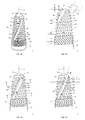
- FIG. 1A to FIG. 1E and FIG. 1H are different views of dental implant according to the present invention.
- a dental implant 1 for dental restoration or dental surgery is placed in a jaw bone 91 (as shown in FIG. 1H ), which includes a body portion 18, a first thread portion 11, a head portion 15, a plurality of second thread portions 12 and two trenches 14.
- the body portion 18 has a drilling axial direction Z along a longitudinal direction thereof.
- the first thread portion 11 is formed on a lower end of the body portion 18 (or one end of the drilling axial direction Z).
- the head portion 15 is formed on an upper end of the body portion 18 (or another end of the drilling axial direction Z).
- the head portion 15 and the first thread portion 11 are respectively arranged at two opposite ends of the body portion 18 along the drilling axial direction Z.
- the first thread portion 11 is a screw thread structure continuously rotated in multiple loops.
- the head portion 15 is arc-shaped head in this emdodiment.
- the second thread portions 12 have a pitch which is larger than a pitch of the first thread portions 11.
- the pitch G2 of the second thread portion 12 is larger than the pitch G1 of the first thread portion 11 (as shown in FIG. 1B ).
- the second thread portion 12 are formed laterally (i.e. approximately along a horizontal direction) on radial sides of the body portion 18. Thus, each second thread portion 12 (as shown in FIG.
- each second thread portion 12 is a piece or a fragment of arc-shaped screw thread (as shown in cross-sectional views of FIG. 1F and FIG. 1G ).
- the second thread portion 12 rotates along the drilling axial direction Z to form a tangent direction J.
- the tangent direction J of the second thread portion 12 and the horizontal line are intersected to form an angle ⁇ (the tangent direction J is generally arranged from lower left toward upper right in FIG. 1D ).
- the angle ⁇ generally is smaller than 20 degrees. Therefore, the direction of the second thread portion 12 (i.e. the direction of the tangent direction J) is substantially arranged in a traverse manner. As a result, when the dental implant 1 is rotated around the drilling axial direction Z , the dental implant 1 can be screwed into the jaw bone 91 gradually by means of the second thread portion 12.
- the plurality of second thread portions 12 are distributed or disposed at different positions along the drilling axial direction Z.
- Each second thread portion 12 has a cutting face 123 and a cumulative face 124 respectively disposed at two opposite ends of the dental implant 1 along the rotative direction P.
- the two opposite ends of the rotative direction P means one end in clockwise direction and another end in counterclockwise.
- the cutting face 123 and the cumulative face 124 are illustrated in detail as shown in FIG. 1C , FIG. 1F and FIG. 1G .
- the X-X cross-sectional view is shown in FIG.
- FIG. 1F the Y-Y cross-sectional view is shown in FIG. 1G .
- the second thread portions 12 are formed at a radial outside of the body portion 18.
- Each second thread portion 12 is substantially arc-shaped along the rotative direction P.
- the cutting face 123 and the cumulative face 124 are arranged at a front and rear ends of the second thread portion 12 along the rotative direction P, namely, one of which is clockwise end and another one is counterclockwise end along the rotative direction P.
- the front end and the rear end (along the rotative direction P) of the second thread portion 12 are contiguous to one of the trenches 14, respectively.
- each of trenches 14 has a front and rear ends along the rotative direction P which are contiguous to one of the second thread portions 12, respectively. Accordingly, the second thread portions 12 and the trenches 14 are formed around a periphery of the body portion 18 in a circle. An interconnecting portion (within the trench 14) between the cutting face 123 and the cumulative face 124 are formed an acute angle corner 149 (i.e. having folding angle). As shown in FIG. 1C , the trench 14 has a trench width D1 approximated to the head portion 15, and a trench width D2 far away from the head portion 15. The trench width D1 is larger or equal to the trench width D2 (i.e. D1 ⁇ D2).
- the trench 14 is filled with bone scrap 92, and therefore the amount of bone scrap 92 at a deeper portion of the jaw bone 91 may be more than the amount of bone scrap 92 at a shallow portion of the jaw bone 91. It therefore provides the dental implant 1 stable fixing structure, and the dental implant 1 in the jaw bone 91 is surrounded and covered by bone or bone scrap 92.
- the trench 14 has a trench depth T1 approximated to the head portion 15, and a trench depth T2 far away from the head portion 15.
- the trench depth T1 is larger than the trench depth T2 (i.e. T1>T2).
- the trench 14 is filled with bone scrap 92, and therefore the amount of bone scrap 92 at a deeper portion of the jaw bone 91 (as shown in FIG. 1F ) may be more than the amount of bone scrap 92 at a shallow portion of the jaw bone 91 (as shown in FIG. 1 G) . It therefore provides the dental implant 1 stable fixing structure.
- a tangent direction of the cutting face 123 and the cutting face 123 are intersected to form an angle ⁇ 1.
- the magnitude of angle ⁇ 1 may affect the difficulty of lateral cutting of the second thread portion 12, in which the lateral cutting is made by the radial sides of the dental implant 1 (i.e. by the cutting face 123).
- a lower end of the dental implant 1 may be formed, connected or coupled with a dental connecting element 17, thus the dental implant 1 can be interconnected or combined with an external piece by the dental connecting element 17.
- the trenches 14 are formed at radial sides of the head portion 15 and the body portion 18, and passed through the plurality of the cutting faces 123 and the cumulative faces 124 from the head portion 15 to the first thread portion 11. In other words, the trenches 14 are downwardly extended from the head portion 15 to the first thread portion 11.
- FIG. 1E of top view which demonstrates embodiment with two trenches 14, being arc-shaped, extended outward in a radial manner from a center of the head portion 15. As shown in FIG.
- the tangent direction J of the second thread portion 12 is intersected with the trench 14 to form an angle ⁇ if the tangent direction J is rotated toward the upper end of the drilling axial direction Z.
- the angle ⁇ is smaller than or equal to 90 degrees (i.e., ⁇ ⁇ 90 degrees).
- the bone scraps 92 can gradually be moved downward inside the trench 14 by moving along a direction away from the head portion 15. If there is osteoporosis at radial sides of the dental implant 1 (the left and right sides as shown in FIG. 1D ), the bone scrap 92 can be pushed to fill the porous portion at the radial sides (i.e. osteoporosis site) during the bone scraps 92 gradually moves downward (along a direction away from the head portion 15).
- the bone scrap 92 could be guided to fill the porous bone at radial sides of the dental implant 1, so that the bone density surrounded the radial side of the dental implant 1 would be increased. Therefore, the surrounding structure around the dental implant 1 is more stable. Further, since the bone scrap 92 is biologically natural components belonged to the patients themselves, the requirements for filling or re-supplying bone graft materials to the radial sides of the dental implant 1 can be reduced, hence the cost of surgery is also reduced.
- the body portion 18 has a diameter H1 approximated to the head portion 15, and a diameter H2 far away from the body portion 18.
- the diameter H1 is smaller than the diameter H2 (that is H1 ⁇ H2).
- the body portion 18 is gradually enlarged from the head portion 15 toward the first thread portion 11 (i.e. taper shaped in cross-sectional view).
- an interconnecting portion between the head portion 15 and the body portion 18 is formed an folding corner (as shown in the partial enlarged view of FIG. 1B ).
- an interval S is formed between the trench 14 and the tip end of the head portion 15.
- the interval S is conformed with an equation of S/H1 ⁇ 0.5, and in a preferred embodiment S/H1 ⁇ 0.3.
- the interval S conformed with the equation of S/H1 ⁇ 0.3 it means the interval S is smaller, and thus the trench 14 is close to the tip end of the dental implant 1 (the lowest end as shown in FIG. 1H ). Accordingly, as the dental implant 1 is rotating along the rotative direction P, the trench 14 can easily cut the jaw bone 91 beneath the dental implant 1. Therefore, the dental implant 1 may be driven to cut downward, and the dental implant 1 may be screwed more deep into the jaw bone 91.
- the arc-shaped head portion can cushion or offset the occlusion force impacted to the jaw bone 91 during biting food.
- the occlusion force is usually exerted the head portion 15 by a vertical force, and the dental implant 1 having blunt head portion 15 can avoid the impact force of chewing food from damage of stress concentration (i.e. biting force is sustained by a relatively small area).
- FIG. 2A Please refer to a cross-sectional view of FIG. 2A .
- the cutting face 123 can shave off the jaw bone 91 thereabout and then accumulate the shaved bone scrap 92 inside the trench 14.
- the cutting face 123 may push and squeeze some of the bone scrap 92, and guide the bone scrap 92 toward a bone defeat portion at the radial side of the dental implant 1 (as shown in FIG. 1D ).
- the second thread portion 12 is able to cut the jaw bone 91. Namely the cutting face 123 located in one end of the second thread portion 12 is able to scrape the jaw bone 91, or squeeze the bone scrap 92.
- FIG. 3A to FIG. 3C are diagrams of drilling resistance of the dental implant according to the present disclosure.
- S/H1 means the interval S is bigger
- FIG. 3B and FIG. 1F as the angle ⁇ 1 is approaching to 90 degrees, the drilling resistance of the dental implant 1 into the jaw bone 91 will become greater and greater. Thus, the rotating torque for rotating the dental implant 1 needs to be increased.
- the second thread portion 12 will be easily burst into pieces if the angle ⁇ 1 is too small.
- the angle ⁇ 1 which is formed by intersection of the tangent direction of the cutting face 123 and the cutting face 123, is preferably conformed with 20 ⁇ ⁇ 1 ⁇ 90 degrees, so as to balance the drilling resistance and mechanical strength (which may endure the stress concentration) of the second thread portion 12.
- a radius R1 is formed between an outermost side of the second thread portion 12 and a center of the body portion 18. As the value of T1/R1 approaching 1.0 (means the trench depth T 1 is bigger), the cutting face 123 will become greater and greater, and thus the drilling resistance of dental implant 1 into deep of the jaw bone 91 will also become larger and larger.
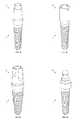
- FIG. 4 is a side view of dental implant of second embodiment according to the present disclosure.
- the second thread portion 12 of the dental implant 1 is rotated around the drilling axial direction Z and formed the tangent direction J.
- the tangent direction J of the second thread portion 12 and a horizontal line are intersected to form an angle ⁇ .
- the tangent direction J is generally orientated from lower left toward upper right.
- the tangent direction J of the second thread portion 12 is slightly slanted, and formed an angle ⁇ if the tangent direction J is rotated toward the lower end of the drilling axial direction Z to intersect with the trench 14 (i.e. the angle ⁇ is intersected by the tangent direction J and the trench 14).
- the angle ⁇ is smaller than or equal to 90 degrees (i.e. ⁇ ⁇ 90 degrees). Consequently, as the dental implant 1 is screwing into the jaw bone 91 in the clockwise direction, the cutting face 123 of the second thread portion 12 moves along the track of tangent direction J and squeeze the bone scrap 92 in the orientation of the tangent direction J. In the meanwhile, since the left wall of the trench 14 (formed by the cutting faces 123 showed in FIG. 4 ) has the inclined angle ⁇ , it may provide or exert the bone scrap 92 an upward component of force. Therefore the bone scraps 92 will gradually be moved upward inside the trench 14, and approached the head portion 15. In this manner, the bone scraps 92 may be moved and guided upward, to approach the head portion 15.
- the bone scraps 92 need to be squeezed and sent upward, to fill the sites neighboring to the head portion 15 (such as sinus membrane); in this scenario, the dentist can utilize the dental implant 1 of this embodiment to push the bone scrap 92 of patients themselves (i.e. natural bone pieces) to apporach the site where approximates to the head portion 15 of the dental implant 1. In this manner, the natural bone scrap 92 which is moved toward the head portion 15 can be utilized to push and squeeze the sinus membrane. As a result, it has no need to fill bone graft material while maxilla implanting is made, and thus the cost for maxillary sinus augmentation may have chance to be saved and the possibility of puncturing the sinus membrane may be eliminated.
- the dental implant 1 of this embodiment equipped with the trenches 14 in a slanting manner may have advantages as following : the natural bone scrap 92 can be guided and filled to an upper portion of the dental implant 1 (toward the head portion 15 or the site neighboring to the head portion 15), and hence the bone scrap 92 can be utilized to squeeze and lift the sinus membrane.
- the tangent direction J of the second thread portion 12 toward the head portion 15 is intersected with the trench 14 to form an angle ⁇ , in which the angle ⁇ is smaller than 90 degrees.
- the bone scrap 92 in the trench 14 therefore can be moved far away from the head portion 15 because the inclined angle ⁇ can provide or exert the bone scrap 92 a downward component of force.
- the trenches 14 of the dental implant 1, as shown in FIG. 1A to FIG. 1H can guide the bone scrap 92 to its radial sides, so as to fill the bone porous portion (osteoporosis) around the radial sides.
- the tangent direction J of the second thread portion 12 toward a lower end (far away from the head portion 15) is intersected with the trench 14, to form an angle ⁇ , in which the angle ⁇ is smaller than 90 degree.
- the bone scrap 92 in the trench 14 therefore can be moved toward the head portion 15 because the inclined angle ⁇ can provide or exert the bone scrap 92 an upward component of force. Accordingly, while the sinus lifting process or bone graft materials re-supplying is needed, the dental implant 1 demonstrated in FIG. 4 can guide the bone scrap 92 toward the head portion 15 by the trenches 14 (technically by the direction of the angle ⁇ ), and then utilize the bone scraps 92 to squeeze and lift the sinus membrane, or to fill the bone porous portion around the head portion 15.
- FIG. 5 is a side view of dental implant of third embodiment according to the present invention.
- the head portion 15 is smoothly connected with the body portion 18 in arc-shaped without acute angle corner.
- the interconnecting area of the head portion 15 and the body portion 18 has a smaller friction resistance, which may bring benefit to the implanting process if the dental implant 1 is drilled into the jaw bone 91.
- the blunt head portion 15 can disperse the occlusion impact while biting food (because the bearing pressure is inversely proportional to the area of thrust surface).
- FIG. 6A a perspective view of dental implant of fourth embodiment according to the present invention
- FIG. 6B is a top view of the dental implant of fourth embodiment of the present invention
- FIG. 6C is a cross-sectional view along the rectangular plane of FIG. 6A .
- the dental implant 1 of this embodiment is formed with three trenches 14 on radial sides of the head portion 15 and the body portion 18.
- FIG. 7A is a perspective view of dental implant of fifth embodiment according to the present invention
- FIG. 7B a front view of the dental implant of the fifth embodiment of the present invention
- FIG. 7C to FIG. 7D are top views of the dental implant of fifth embodiment according to the present invention.
- the second thread portions 12 are rotated along the drilling axial direction Z and forms a tangent direction J.
- the tangent direction J of the second thread portion 12 is intersected with the horizontal line to form an angle ⁇ .
- the dental implant 1 Since the tangent direction J is generally orientated from lower right toward upper left, the dental implant 1 needs to be rotated in counterclockwise direction (around the drilling axial direction Z) to screw the dental implant 1 into the jaw bone 91.
- the dental implant 1 of this embodiment is drilled into patient's jaw bone 91 in a counterclockwise direction, comparatively the dental implant 1 in FIG. 1D is drilled in a clockwise direction.
- this embodiment has four trenches 14 on radial sides of the head portion 15 and the body portion 18.
- the tangent direction J of the second thread portion 12 toward an upper end of the drilling axial direction Z is intersected with the trench 14 to form an angle ⁇ as shown in FIGS. 7B , and the angle ⁇ is smaller than 90 degrees (that is, ⁇ ⁇ 90 degrees).
- the dental implant 1 of this embodiment is screwed in the jaw bone 91, the cutting face 123 of the second thread portion 12 will move in the tangent direction J, and squeeze the bone scraps 92 toward the tangent direction J.
- FIG. 7C and FIG. 7D illustrate different types of trench 14 and different head portion 15.
- the trenches 14 are formed around a periphery of the head portion 15 in a circle.
- FIG. 7E is a side view of derivative dental implant according to the fifth embodiment of the present invention.
- the second thread portion 12 of the dental implant 1 is rotated around the drilling axial direction Z and forms a tangent direction J.
- the tangent direction J of the second thread portion 12 is intersected with the horizontal line to form an angle ⁇ .
- the tangent direction J is generally orientated from lower right toward upper left.
- the tangent direction J of the second thread portion 12 toward a lower end of the drilling axial direction Z is intersected with the trench 14 so as to form an angle ⁇ , and the angle ⁇ is smaller than 90 degrees (i.e. ⁇ ⁇ 90 degrees).
- this embodiment can utilize the bone scraps 92 upward moving mechanism (toward the head portion 15) to squeeze or urge the bone scraps 92 to move and fill the site neighboring to the sinus membrane or the head portion 15.
- FIG. 8A to FIG. 8B illustrate the dental implant having different cutting faces according to the present invention.
- FIG. 8A there are three trenches 14 and three second thread portions 12 surrounded around the body portion 18. Two sides of each trench 14 are surrounded with a cutting face 123 and a cumulative face 124 respectively.
- the cutting face 123 of the second thread portion 12 has a curvature radius R3, and the tangent direction of the cutting face 123 is intersected with the cutting face 123 so as to form an angle ⁇ 1.
- the angle ⁇ 1 is preferably about 25 to 60 degrees, so that it may give considerations to the cutting effect and structural strength of the second thread portion 12 (in a practical case, 60 ⁇ ⁇ 1 ⁇ 90 degrees may be available).
- a curvature radius R3 of the cutting face 123 is smaller than a radius R1 of the second thread portion 12 (that is, R3 ⁇ R1).
- an occupied space of the trench 14 is greater than that of the embodiment of FIG. 6C , therefore the trenches 14 in this embodiment can accommodate much more bone scrap 92. If one having tooth with thinner roots (means the bone around the real tooth is relatively sufficient) needs to be extracted, the dental implant 1 of FIG.
- the cutting face 123 of the second thread portion 12 is a plane (revealed in a straight line in FIG. 8B ), so that the curvature radius R3 of the cutting face 123 is infinity.
- the drilling resistance of the dental implant 1 in FIG. 8A and FIG. 8B shown in FIG. 8C , the drilling resistance of the dental implant 1 into the jaw bone 91 is become greater when the curvature radius R3 is increasing along with the cutting face 123. The reason is that more curved cutting face 123 (curvature radius R3 becomes smaller) can guide the bone scrap 92 slightly to move in a radial direction.
- both of the cutting face 123 and the cumulative face 124 have arc-shaped cross-section, and an interconnecting area among the cutting face 123 and the cumulative face 124 at two sides of the trench 14 has an acute angle corner 149.
- cross-sections of the cutting face 123 and the cumulative face 124 are revealed as straight line, and an interconnecting area among the cutting face 123 and the cumulative face 124 at two sides of the trench 14 has no acute angle corner. Since there is no acute angle corner between the cutting face 123 and the cumulative face 124, it helps to guide movement of the bone scrap 92 in the trench 14.
- FIG. 9A and FIG. 9B are cross-sectional views of dental implant with different area of body portion.
- FIG. 9C is diagram showing the drilling resistance related to body portion 18, second thread portion 12 and sectional area (A) of FIG. 9A and FIG. 9B .
- a space of the trench 14 in FIG. 9A is larger than a space of trench 14 in FIG. 9B , so that the body portion 18 with three second thread portions 12 in FIG. 9A has a sectional area (A) smaller than that of the embodiment of FIG. 9B .
- Reason is that the sectional area (A), sum of area of the body portion 18 and the second thread portions 12, will raise difficulty for the dental implant 1 drilling into the deep of the jaw bone 91. As shown in FIG.
- one fictitious circle can be defined by the radius R1 of the second thread portion 12, and the area of the fictitious circle is equal to ⁇ *R1*R1. If a ratio of the sectional area (A) of the body portion 18 plus the second thread portions 12 to the area of the fictitious circle ⁇ *R1*R1 is more approaching 1.0 (means the space of the trench 14 is smaller, and the sectional area (A) is greater), the drilling resistance of the dental implant 1 into the deep of the jaw bone 91 is become larger and larger. The reason is that less space to receive and accommodate the bone scrap 92 may raise difficult for the dental implant 1 to drill into the jaw bone 91. Furthermore, the bone scrap 92 might have chance to stick or block inside the trenches 14 when the bone scrap 92 is naturally generated.
- FIG. 10A is an enlarged view of head portion of dental implant of the present invention.
- FIG. 10B is a diagram of drilling resistance related to inclined angle ( ⁇ ) of head portion according to FIG. 10A .
- the head portion 15 of the dental implant 1 includes a peak 156, which has an inclined angle ⁇ and formed along the contour of the head portion 15.
- the dental implant 1 is easily to have stress concentration occurred at the site of the peak 156 when the jaw bone 91 is bearing the occlusion impact of biting food. The destructive power and impact caused by the stress concentration may damage the jaw bone 91.
- the inclined angle ⁇ is too small (means the head portion 15 is too obtuse), the drilling force of the dental implant 1 into the jaw bone 91 is greater, which is not good for the dentist to perform a dental implantation surgery on the jaw bone 91 (as shown in FIG. 10B ).
- the inclined angle ⁇ conformed with 0 ⁇ ⁇ ⁇ 30 degrees may give consideration to the drilling effect and avoiding the problem of stress concentration.
- FIG. 11 is an enlarged cross-sectional view of head portion of dental implant of sixth embodiment according to the present invention.
- the head portion 15 has a straight section 157 and a curve section 158, and a inclined angle ⁇ is formed by an intersection of the straight section 157 and the peak 156.
- the curve section 158 is arranged outside the straight section 157.
- the head portion 15 could be formed without the peak156, so that a lateral cross-section of the head portion 15 can be arc-shaped or planar.
- the arc or outside of plane can be connected with a straight line of an arc with different curvature, so that the lateral cross-section of the head portion 15 can be configured as many line segments.
- FIG. 12 is a contour view of dental implant of seventh embodiment according to the present invention.
- the body portion 18 of the dental implant 1 has a diameter H1 close to the head portion 15, and a diameter H2 far away from the head portion 15.
- the pitches G2 between the second thread portions 12 are the same, no matter close to or far away from the head portion 15. In this manner, the dental implant 1 rotates by one cycle along the rotative direction P will drill to move a distance of pitch G2 toward the deep of the jaw bone 91.
- the bases of the second thread portions 12 are connected with the body portion 18 to form a base width K1, K2.
- the second thread portion 12 may have more and more surface to contact with the jaw bone 91 because the site of base width K2 has greater surface area than the site of base width K2. More contact surface brings more osseous integration and more friction between the dental implant 1 and the jaw bone 91. Therefore the mechanical strength of dental implant 1 or the resistance against the occlusion force of biting food is absolutely greater and greater.
- FIG. 13 is a contour view of dental implant of eighth embodiment according to the present invention.
- the second thread portion 12 has a thread height F1 close to the head portion 15, and a thread height F2 far away from the head portion 15.
- the thread height F1 is smaller than the thread height F2 (i.e. F1 ⁇ F2). Because F 1 is smaller than F2, the crests 125 of the second thread portions 12 at sides of the dental implant 1 may be extended and intersected to form an intersection angle ⁇ 1.
- the intersection angle ⁇ 1 is about smaller than 30 degrees.
- FIG. 14 is a contour view of dental implant of ninth embodiment according to the present invention.
- the crests 125 of the second thread portion 12 may be extended and intersected to form an intersection angle ⁇ 1, which is conformed with 0 ⁇ ⁇ 1 ⁇ 30 degrees.
- the body portion 18 has a cross-section along an axial direction of the dental implant 1 ( along the drilling axial direction Z), and an intersection angle ⁇ 2 is defined by side edges of the body portion 18. In this embodiment, it conforms with ⁇ 1 ⁇ ⁇ 2.
- the body portion 18 has a diameter H1 close to the head portion 15, in which the diameter H1 is smaller than a diameter H2 of the body portion 18 far away from the head portion 15 (i.e. H1 ⁇ H2).
- this configuration demonstrated in FIG. 14 has thread height F2 greater than the thread height F1, and the base width K2 greater than or equal to the base width K1 (i.e. H2>H1, F2>F1, K2 ⁇ K1).
- FIG. 15 is a contour view of dental implant of tenth embodiment according to the present invention
- FIG. 16 shows a contour view of dental implant of eleventh embodiment according to the present invention
- FIG. 17 shows a contour view of dental implant of twelfth embodiment according to the present invention.
- the second thread portions 12 of the dental implant 1 have crests 125, and the crests 125 are peak-shaped.
- the crests 125 of the second thread portions 12 are jagged-shaped.
- the crests 125 of the second thread portions 12 are arc-shaped.
- the second thread portion 12 further has a main sustaining face 121 and a secondary sustaining face 122.
- the main sustaining face 121 is close to the head portion 15, and the secondary sustaining face 122 is far away from the head portion 15.
- the main sustaining face 121 and the horizontal line are intersected to form an angle ⁇ 1 (means the slanting angle of the main sustaining face 121).
- the secondary sustaining face 122 and the horizontal line are intersected to form an angle ⁇ 2 (means the slanting angle of the secondary sustaining face 122).
- ⁇ 1 can be equal to ⁇ 2.
- ⁇ 1 is smaller than ⁇ 2; namely the main sustaining face 121 has more gradual angle (i.e. less inclined) than the secondary sustaining face 122.
- the second thread portion 12 can resist or sustain a greater occlusion force from biting if the dental implant 1 is buried in the jaw bone 91. More gradual main sustaining face 121 can withstand higher occlusion force.
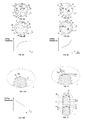
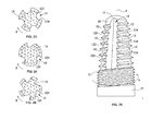
- FIG. 18 to FIG. 22 are perspective views of dental implant of thirteenth embodiment according to the present invention.
- the dental connecting element 17 can be dental abutments with different configurations, dental crowns, dental tools or any connecting structure for dismounting or linking, engaging structure or wedging structure.
- the dental implant 1 and the dental connecting element 17 may be fixed together (one piece structure) as shown in FIG. 18 to FIG. 22 , or may be detachable structure (i.e. can be assembled in separable manner).
- FIG. 23 is a cross-sectional view of dental implant of fourteenth embodiment according to the present invention.
- the dental implant 1 has four trenches 14. Each trench 14 has a cross-section of half-circle. In other words, each trench 14 is surrounded by the cutting face 123 and the cumulative face 124 which are curve with equal curvature radius.
- FIG. 24 which is a cross-sectional view of dental implant of fifteenth embodiment according to the present invention. In this embodiment, the dental implant 1 has three trenches 14. Each trench 14 is surrounded by the cutting face 123 and the cumulative face 124 which are curved surface with different curvature. Please refer to FIG.
- the dental implant 1 has five trenches 14. Each trench 14 is surrounded by the cutting face 123 the cumulative face 124 which are planar structure.
- the dental implant 1 can be formed by two, three, fourth, five or more trenches 14, and the shape or contour of the cutting face 123 and the cumulative face 124 can be any configuration of above-mentioned embodiments.
- FIG. 26 is a side view of dental implant of fourteenth embodiment according to the present invention.
- the trench 14 is substantially parallel to the drilling axial direction Z.
- the trench 14 is formed at radial sides of the head portion 15 and the body portion 18, and is arranged approximating to the vertical.
- the trench 14 can be exactly parallel to the drilling axial direction Z.
- the trench 14 may be intersected with the drilling axial direction Z to form a small angle (not shown).
- all the structure relationship between the second thread portion 12, trench 14, head portion 15, body portion 18 can be optionally selected from any one of the above-mentioned structural feature.
- the dental implant 1 of the present invention is able to be directly screwed into the jaw bone 91 after real tooth is removed, so that the dentist can screw the dental implant 1 to the site of missing tooth by rotating the dental implant 1.
- the dental drilling engine e.g. dental hand piece, or dental drill
- the time for dental implant surgery can be shortened, and oral injuries and patient's pain can be reduced, as well as the time for gingiva healing period after dental implantation may also be saved.
- the dental implant 1 no matter titanium or zirconium, can be applied to one-piece implant and two-piece implant; thus the indirect advantages are: avoiding the jaw bone 91 from being drilled many times and dug repeatedly, and preventing surgery error happened and over-deep drilling. If the upper jaw which contains maxillary sinus is drilled too deep, it may impale or break through the sinus membrane. If the lower jaw is drilled too deep, the facial nerve may be dug broken. Further, the dental implant 1 has the trenches 14 formed along an orientation angle ⁇ , and the trench 14 is extended from the head portion 15 toward the first thread portion 11. Therefore the bone scraps 92 in the trench 14 can be guided to the head portion 15 (as shown in FIG.
- the dental implant 1 of the present invention has the dental treatment potential for realizing application.
Landscapes
- Health & Medical Sciences (AREA)
- Oral & Maxillofacial Surgery (AREA)
- Orthopedic Medicine & Surgery (AREA)
- Dentistry (AREA)
- Epidemiology (AREA)
- Life Sciences & Earth Sciences (AREA)
- Animal Behavior & Ethology (AREA)
- General Health & Medical Sciences (AREA)
- Public Health (AREA)
- Veterinary Medicine (AREA)
- Otolaryngology (AREA)
- Dental Prosthetics (AREA)
Applications Claiming Priority (1)
| Application Number | Priority Date | Filing Date | Title |
|---|---|---|---|
| TW103215902U TWM500558U (zh) | 2014-09-05 | 2014-09-05 | 五合一植牙手術之植牙體 |
Publications (2)
| Publication Number | Publication Date |
|---|---|
| EP3000428A2 true EP3000428A2 (de) | 2016-03-30 |
| EP3000428A3 EP3000428A3 (de) | 2016-06-29 |
Family
ID=53722347
Family Applications (1)
| Application Number | Title | Priority Date | Filing Date |
|---|---|---|---|
| EP15183400.9A Withdrawn EP3000428A3 (de) | 2014-09-05 | 2015-09-01 | Zahnimplantat |
Country Status (5)
| Country | Link |
|---|---|
| EP (1) | EP3000428A3 (de) |
| AU (1) | AU2015221485A1 (de) |
| BR (1) | BR102015021752A2 (de) |
| RU (1) | RU2015137397A (de) |
| TW (1) | TWM500558U (de) |
Cited By (2)
| Publication number | Priority date | Publication date | Assignee | Title |
|---|---|---|---|---|
| RU2711546C1 (ru) * | 2019-04-19 | 2020-01-17 | Александр Васильевич Потапов | Базальный имплантат |
| CN113397735A (zh) * | 2020-03-16 | 2021-09-17 | 陈俊龙 | 单钻植牙系统及其使用方法 |
Families Citing this family (1)
| Publication number | Priority date | Publication date | Assignee | Title |
|---|---|---|---|---|
| US10188489B2 (en) | 2014-04-17 | 2019-01-29 | Star Generation Limited Taiwan Branch | Sinus implant |
Family Cites Families (5)
| Publication number | Priority date | Publication date | Assignee | Title |
|---|---|---|---|---|
| US20090130631A1 (en) * | 2006-11-30 | 2009-05-21 | Chun-Leon Chen | Implant root for tooth implanting |
| WO2009142429A2 (ko) * | 2008-05-19 | 2009-11-26 | 오스템임플란트(주) | 치과용 임플란트 픽스쳐 |
| ITPD20090009U1 (it) * | 2009-02-09 | 2010-08-10 | Btlock Internat S R L | Struttura di impianto per il fissaggio di protesi dentarie |
| TWM390130U (en) * | 2010-04-15 | 2010-10-11 | jun-long Chen | One piece angle implant |
| CN201759692U (zh) * | 2010-06-24 | 2011-03-16 | 陈俊龙 | 可修复式单件植牙体 |
-
2014
- 2014-09-05 TW TW103215902U patent/TWM500558U/zh unknown
-
2015
- 2015-09-01 EP EP15183400.9A patent/EP3000428A3/de not_active Withdrawn
- 2015-09-02 RU RU2015137397A patent/RU2015137397A/ru not_active Application Discontinuation
- 2015-09-02 AU AU2015221485A patent/AU2015221485A1/en not_active Abandoned
- 2015-09-04 BR BR102015021752A patent/BR102015021752A2/pt not_active IP Right Cessation
Cited By (2)
| Publication number | Priority date | Publication date | Assignee | Title |
|---|---|---|---|---|
| RU2711546C1 (ru) * | 2019-04-19 | 2020-01-17 | Александр Васильевич Потапов | Базальный имплантат |
| CN113397735A (zh) * | 2020-03-16 | 2021-09-17 | 陈俊龙 | 单钻植牙系统及其使用方法 |
Also Published As
| Publication number | Publication date |
|---|---|
| AU2015221485A1 (en) | 2016-03-24 |
| BR102015021752A2 (pt) | 2016-08-30 |
| RU2015137397A (ru) | 2017-03-09 |
| EP3000428A3 (de) | 2016-06-29 |
| TWM500558U (zh) | 2015-05-11 |
Similar Documents
| Publication | Publication Date | Title |
|---|---|---|
| US20150297321A1 (en) | Dental Implant | |
| JP5562963B2 (ja) | 歯科インプラントを埋入するための装置および手順 | |
| US8221119B1 (en) | Dental implant and method of installing the same | |
| AU2013250151B2 (en) | Tooth implant | |
| US8142190B2 (en) | Set of motor-driven instruments to aid the fixing of dental implants | |
| EP2919672B1 (de) | Autotransplantationsosteotom | |
| EP1952781A2 (de) | Verankerungselement zur Verwendung in Knochen | |
| US20140141388A1 (en) | Dental Implant and Method of Implantation | |
| US12419651B2 (en) | Condensing screw for implant procedure having double spiral structure | |
| CN102458299A (zh) | 用于窦底提升和侧嵴扩增的植入物、工具和方法 | |
| CN207084863U (zh) | 种植牙用钻机及具有其种植牙用钻机装置 | |
| JP2016503666A (ja) | 凝縮インプラント | |
| WO2012154053A1 (en) | Process for securing a dental implant and dental implant | |
| EP3000428A2 (de) | Zahnimplantat | |
| US20140030674A1 (en) | Prefabricated immediate no-drill dental implant | |
| KR101234296B1 (ko) | 임플란트 시술용 드릴 | |
| EP3253327A1 (de) | Zahnimplantat zur vereinfachten implantation und stabilisierung | |
| US11660168B2 (en) | Dental implant | |
| TW201540268A (zh) | 植牙體結構 | |
| KR100864085B1 (ko) | 임플랜트시스템 | |
| KR100743181B1 (ko) | 치과용 응급 임플란트의 내부결합형 픽스츄어 | |
| KR200429575Y1 (ko) | 치과용 응급 임플란트의 내부결합형 픽스츄어 | |
| US20250082436A1 (en) | Simplified system and procedure for computer-guided dental implant surgery | |
| TWI379666B (en) | Dental implant | |
| CN107320206A (zh) | 一种牙种植导板工具 |
Legal Events
| Date | Code | Title | Description |
|---|---|---|---|
| PUAI | Public reference made under article 153(3) epc to a published international application that has entered the european phase |
Free format text: ORIGINAL CODE: 0009012 |
|
| 17P | Request for examination filed |
Effective date: 20150903 |
|
| AK | Designated contracting states |
Kind code of ref document: A2 Designated state(s): AL AT BE BG CH CY CZ DE DK EE ES FI FR GB GR HR HU IE IS IT LI LT LU LV MC MK MT NL NO PL PT RO RS SE SI SK SM TR |
|
| AX | Request for extension of the european patent |
Extension state: BA ME |
|
| PUAL | Search report despatched |
Free format text: ORIGINAL CODE: 0009013 |
|
| AK | Designated contracting states |
Kind code of ref document: A3 Designated state(s): AL AT BE BG CH CY CZ DE DK EE ES FI FR GB GR HR HU IE IS IT LI LT LU LV MC MK MT NL NO PL PT RO RS SE SI SK SM TR |
|
| AX | Request for extension of the european patent |
Extension state: BA ME |
|
| RIC1 | Information provided on ipc code assigned before grant |
Ipc: A61C 8/00 20060101AFI20160524BHEP |
|
| STAA | Information on the status of an ep patent application or granted ep patent |
Free format text: STATUS: THE APPLICATION IS DEEMED TO BE WITHDRAWN |
|
| 18D | Application deemed to be withdrawn |
Effective date: 20170103 |