EP3000418A1 - Device for treatment of the human or animal body with mechanical impacts - Google Patents
Device for treatment of the human or animal body with mechanical impacts Download PDFInfo
- Publication number
- EP3000418A1 EP3000418A1 EP14186613.7A EP14186613A EP3000418A1 EP 3000418 A1 EP3000418 A1 EP 3000418A1 EP 14186613 A EP14186613 A EP 14186613A EP 3000418 A1 EP3000418 A1 EP 3000418A1
- Authority
- EP
- European Patent Office
- Prior art keywords
- applicator
- impact
- curvature
- concave
- projectile
- Prior art date
- Legal status (The legal status is an assumption and is not a legal conclusion. Google has not performed a legal analysis and makes no representation as to the accuracy of the status listed.)
- Granted
Links
- 241001465754 Metazoa Species 0.000 title claims abstract description 5
- 230000035939 shock Effects 0.000 claims description 7
- 229920003023 plastic Polymers 0.000 claims description 5
- 239000004033 plastic Substances 0.000 claims description 5
- RTAQQCXQSZGOHL-UHFFFAOYSA-N Titanium Chemical compound [Ti] RTAQQCXQSZGOHL-UHFFFAOYSA-N 0.000 claims description 3
- 229910052751 metal Inorganic materials 0.000 claims description 3
- 239000002184 metal Substances 0.000 claims description 3
- 239000010936 titanium Substances 0.000 claims description 3
- 229910052719 titanium Inorganic materials 0.000 claims description 3
- 229910052782 aluminium Inorganic materials 0.000 claims description 2
- XAGFODPZIPBFFR-UHFFFAOYSA-N aluminium Chemical compound [Al] XAGFODPZIPBFFR-UHFFFAOYSA-N 0.000 claims description 2
- 239000000919 ceramic Substances 0.000 claims description 2
- 241000234295 Musa Species 0.000 description 4
- 235000018290 Musa x paradisiaca Nutrition 0.000 description 4
- 229910001220 stainless steel Inorganic materials 0.000 description 3
- 239000010935 stainless steel Substances 0.000 description 3
- 230000001133 acceleration Effects 0.000 description 2
- 230000008878 coupling Effects 0.000 description 2
- 238000010168 coupling process Methods 0.000 description 2
- 238000005859 coupling reaction Methods 0.000 description 2
- 239000000463 material Substances 0.000 description 2
- 150000002739 metals Chemical class 0.000 description 2
- 208000000913 Kidney Calculi Diseases 0.000 description 1
- 206010029148 Nephrolithiasis Diseases 0.000 description 1
- 238000012512 characterization method Methods 0.000 description 1
- 238000010276 construction Methods 0.000 description 1
- 230000007423 decrease Effects 0.000 description 1
- 230000001419 dependent effect Effects 0.000 description 1
- 229920001971 elastomer Polymers 0.000 description 1
- 239000000806 elastomer Substances 0.000 description 1
- 239000012530 fluid Substances 0.000 description 1
- 230000005484 gravity Effects 0.000 description 1
- 230000001939 inductive effect Effects 0.000 description 1
- 239000007769 metal material Substances 0.000 description 1
- 210000003205 muscle Anatomy 0.000 description 1
- NJPPVKZQTLUDBO-UHFFFAOYSA-N novaluron Chemical compound C1=C(Cl)C(OC(F)(F)C(OC(F)(F)F)F)=CC=C1NC(=O)NC(=O)C1=C(F)C=CC=C1F NJPPVKZQTLUDBO-UHFFFAOYSA-N 0.000 description 1
- 230000000284 resting effect Effects 0.000 description 1
- 239000000523 sample Substances 0.000 description 1
- 210000001991 scapula Anatomy 0.000 description 1
- -1 stainless steel Chemical class 0.000 description 1
- 239000004575 stone Substances 0.000 description 1
- 239000000725 suspension Substances 0.000 description 1
- 230000001225 therapeutic effect Effects 0.000 description 1
- 210000001519 tissue Anatomy 0.000 description 1
- 230000001960 triggered effect Effects 0.000 description 1
- 238000013022 venting Methods 0.000 description 1
Images

Classifications
-
- A—HUMAN NECESSITIES
- A61—MEDICAL OR VETERINARY SCIENCE; HYGIENE
- A61B—DIAGNOSIS; SURGERY; IDENTIFICATION
- A61B17/00—Surgical instruments, devices or methods, e.g. tourniquets
- A61B17/22—Implements for squeezing-off ulcers or the like on the inside of inner organs of the body; Implements for scraping-out cavities of body organs, e.g. bones; Calculus removers; Calculus smashing apparatus; Apparatus for removing obstructions in blood vessels, not otherwise provided for
- A61B17/22004—Implements for squeezing-off ulcers or the like on the inside of inner organs of the body; Implements for scraping-out cavities of body organs, e.g. bones; Calculus removers; Calculus smashing apparatus; Apparatus for removing obstructions in blood vessels, not otherwise provided for using mechanical vibrations, e.g. ultrasonic shock waves
-
- A—HUMAN NECESSITIES
- A61—MEDICAL OR VETERINARY SCIENCE; HYGIENE
- A61B—DIAGNOSIS; SURGERY; IDENTIFICATION
- A61B17/00—Surgical instruments, devices or methods, e.g. tourniquets
- A61B17/22—Implements for squeezing-off ulcers or the like on the inside of inner organs of the body; Implements for scraping-out cavities of body organs, e.g. bones; Calculus removers; Calculus smashing apparatus; Apparatus for removing obstructions in blood vessels, not otherwise provided for
- A61B17/225—Implements for squeezing-off ulcers or the like on the inside of inner organs of the body; Implements for scraping-out cavities of body organs, e.g. bones; Calculus removers; Calculus smashing apparatus; Apparatus for removing obstructions in blood vessels, not otherwise provided for for extracorporeal shock wave lithotripsy [ESWL], e.g. by using ultrasonic waves
- A61B17/2251—Implements for squeezing-off ulcers or the like on the inside of inner organs of the body; Implements for scraping-out cavities of body organs, e.g. bones; Calculus removers; Calculus smashing apparatus; Apparatus for removing obstructions in blood vessels, not otherwise provided for for extracorporeal shock wave lithotripsy [ESWL], e.g. by using ultrasonic waves characterised by coupling elements between the apparatus, e.g. shock wave apparatus or locating means, and the patient, e.g. details of bags, pressure control of bag on patient
-
- A—HUMAN NECESSITIES
- A61—MEDICAL OR VETERINARY SCIENCE; HYGIENE
- A61H—PHYSICAL THERAPY APPARATUS, e.g. DEVICES FOR LOCATING OR STIMULATING REFLEX POINTS IN THE BODY; ARTIFICIAL RESPIRATION; MASSAGE; BATHING DEVICES FOR SPECIAL THERAPEUTIC OR HYGIENIC PURPOSES OR SPECIFIC PARTS OF THE BODY
- A61H9/00—Pneumatic or hydraulic massage
- A61H9/005—Pneumatic massage
-
- A—HUMAN NECESSITIES
- A61—MEDICAL OR VETERINARY SCIENCE; HYGIENE
- A61B—DIAGNOSIS; SURGERY; IDENTIFICATION
- A61B17/00—Surgical instruments, devices or methods, e.g. tourniquets
- A61B17/56—Surgical instruments or methods for treatment of bones or joints; Devices specially adapted therefor
-
- A—HUMAN NECESSITIES
- A61—MEDICAL OR VETERINARY SCIENCE; HYGIENE
- A61H—PHYSICAL THERAPY APPARATUS, e.g. DEVICES FOR LOCATING OR STIMULATING REFLEX POINTS IN THE BODY; ARTIFICIAL RESPIRATION; MASSAGE; BATHING DEVICES FOR SPECIAL THERAPEUTIC OR HYGIENIC PURPOSES OR SPECIFIC PARTS OF THE BODY
- A61H23/00—Percussion or vibration massage, e.g. using supersonic vibration; Suction-vibration massage; Massage with moving diaphragms
- A61H23/008—Percussion or vibration massage, e.g. using supersonic vibration; Suction-vibration massage; Massage with moving diaphragms using shock waves
-
- A—HUMAN NECESSITIES
- A61—MEDICAL OR VETERINARY SCIENCE; HYGIENE
- A61B—DIAGNOSIS; SURGERY; IDENTIFICATION
- A61B90/00—Instruments, implements or accessories specially adapted for surgery or diagnosis and not covered by any of the groups A61B1/00 - A61B50/00, e.g. for luxation treatment or for protecting wound edges
- A61B90/08—Accessories or related features not otherwise provided for
- A61B2090/0817—Spatulas or spatula like extensions
-
- A—HUMAN NECESSITIES
- A61—MEDICAL OR VETERINARY SCIENCE; HYGIENE
- A61H—PHYSICAL THERAPY APPARATUS, e.g. DEVICES FOR LOCATING OR STIMULATING REFLEX POINTS IN THE BODY; ARTIFICIAL RESPIRATION; MASSAGE; BATHING DEVICES FOR SPECIAL THERAPEUTIC OR HYGIENIC PURPOSES OR SPECIFIC PARTS OF THE BODY
- A61H2201/00—Characteristics of apparatus not provided for in the preceding codes
- A61H2201/01—Constructive details
- A61H2201/0157—Constructive details portable
-
- A—HUMAN NECESSITIES
- A61—MEDICAL OR VETERINARY SCIENCE; HYGIENE
- A61H—PHYSICAL THERAPY APPARATUS, e.g. DEVICES FOR LOCATING OR STIMULATING REFLEX POINTS IN THE BODY; ARTIFICIAL RESPIRATION; MASSAGE; BATHING DEVICES FOR SPECIAL THERAPEUTIC OR HYGIENIC PURPOSES OR SPECIFIC PARTS OF THE BODY
- A61H2201/00—Characteristics of apparatus not provided for in the preceding codes
- A61H2201/50—Control means thereof
-
- A—HUMAN NECESSITIES
- A61—MEDICAL OR VETERINARY SCIENCE; HYGIENE
- A61H—PHYSICAL THERAPY APPARATUS, e.g. DEVICES FOR LOCATING OR STIMULATING REFLEX POINTS IN THE BODY; ARTIFICIAL RESPIRATION; MASSAGE; BATHING DEVICES FOR SPECIAL THERAPEUTIC OR HYGIENIC PURPOSES OR SPECIFIC PARTS OF THE BODY
- A61H2205/00—Devices for specific parts of the body
- A61H2205/06—Arms
- A61H2205/062—Shoulders
-
- A—HUMAN NECESSITIES
- A61—MEDICAL OR VETERINARY SCIENCE; HYGIENE
- A61H—PHYSICAL THERAPY APPARATUS, e.g. DEVICES FOR LOCATING OR STIMULATING REFLEX POINTS IN THE BODY; ARTIFICIAL RESPIRATION; MASSAGE; BATHING DEVICES FOR SPECIAL THERAPEUTIC OR HYGIENIC PURPOSES OR SPECIFIC PARTS OF THE BODY
- A61H2205/00—Devices for specific parts of the body
- A61H2205/08—Trunk
Definitions
- the present invention relates to an apparatus for treating the human or animal body by exerting impacts on the body surface.
- the following is spoken of the body of a patient, who is preferably human.
- the DE 197 25 477 C describes, for example, such a device in which a pressure wave is triggered by the collision of a pneumatically accelerated striker or projectile with an initially stationary baffle or applicator, which can be coupled into the body of the patient that an applicator front surface at the time of the collision on the Patient body is hung up.
- This type of device is derived in its history from Lithotripsie fürn from where such pressure waves z. B. on a long rod-shaped probe on the front surface of the applicator on a kidney stone or the like can be transferred to disintegrate it.
- the focus in the presentation is in any case on the pressure wave generated by the collision, which should more or less resemble an actual shock wave, as they are classic lithotripsy devices z. B. with piezoelectric or inductive actuators and focus on a stone.
- Such pressure waves may have leading edges with a width in the range of a few ⁇ s and an amplitude in the low two-digit MPa range (eg 2 ⁇ s and 15 MPa measured 1 cm in front of the front surface).
- the physically inherently unavoidable macroscopic center of gravity movement of the applicator should be kept as small as possible, because it is regarded as disturbing.
- the DE 20 2004 011 323 U and, with very similar content, the US 2011/0054367 A1 directed.
- a similar device with respect to the technical structure is described in which, however, inter alia, the elastic suspension of the applicator in the housing is designed for larger center-of-gravity movements of the applicator ("strokes").
- strokes center-of-gravity movements of the applicator
- the present invention is generally directed to devices of this type of construction, both in terms of the application of pressure waves and the application of "macroscopic shocks" of the applicator to the body surface.
- the invention has the object to further develop such a device with regard to further applications.
- the applicator is bent-flat and has according to the bend on a concave and an oppositely disposed convex side surface. These side surfaces correspond in shape to the extent that the applicator has a limited thickness therebetween, that is to say "flat”, which is substantiated to a limit of at most 1/3 of the applicator extension along the concave and the convex side surface.
- the length (in a straight line, not curved in the curve below) of the applicator from the beginning to the end of the described curved shape is about 30 mm, for example, as in the exemplary embodiment, the thickness between the convex and the concave side surface should be at most 10 mm, preferably at most 1/4 or even at most 1/5 thereof, ie at most in the example 7.5 or at most 6 mm.
- thicker areas of the applicator are not fundamentally excluded, for example in the vicinity of its mounting section to connect to the rest of the device. However, they do not reckon with the shape according to the invention and preferably they are not provided distally, but at most proximally thereof (the terms proximal and distal refer to the direction of impact).
- the invention has proven itself in the treatment of muscles within the scapula; Again, the therapist can grip around the shoulder blade with the applicator.
- the convex side is at the same time as an inclined surface for stroking movements on the body surface with oblique attitude of the device relative to the body surface. Then the device gets better and can be guided over the body surface in a more controllable and comfortable way for the therapist.
- tissue sections under the skin can be massaged in parallel and / or pushed to a certain extent in front of the device, whereby they are acted on simultaneously with the shocks and (in a different case by case measure) pressure waves.
- the conventionally known devices with more or less flat front surfaces of the applicators are relatively poorly suited because they are on the skin surface can be held only at more or less vertical position of the device relative to the body surface.
- the mechanism for generating the shocks of the applicator is in this context conceivable in a wide variety of embodiments, in particular by direct application of the applicator by means of an electromagnetic mechanism or a pressure fluid pulse.
- an accelerated projectile for collision with the applicator which is already known from the cited documents is preferred, whereby relatively fast and (in the sense of the applicator speed) rapid impacts can be realized and also the simultaneous or even main use of pressure waves is possible.
- the projectile in turn, can also be accelerated in different ways, in particular also electromagnetically, in which case a pneumatic application of the projectile according to the cited documents is also preferred.
- the term "applicator” does not necessarily mean an integral part here. It is conceivable and application-dependent also preferred that the projectile z. B. strikes a first part that transmits the shock and / or the pressure wave to a second applicator, which in turn is in contact with the skin of the patient. The prior art also occasionally mentions an intermediate piece between the applicator and the projectile; Here is then spoken of a multi-part applicator, wherein the two Applikatormaschine can be firmly connected, but need not be.
- the device is preferably designed so that strokes over 1 mm can be achieved, as already in the US 2011/0054367 A1 executed.
- the applicator according to the invention has exactly the one curvature curve described, that is to say no other with a different curvature, approximately opposite or in a significantly different level of curvature.
- Such a simple applicator is not only advantageous in terms of manufacturability, but also practical and complication-free in the application.
- the convex and the concave side surface are preferably such that a sectional plane in which the respective curvature is particularly pronounced, contains the impact direction and the occurring centers of curvature with respect to the impact direction are located laterally next to the applicator.
- the applicator form bends so that the convex side surface is toward one side (and not forward or backward with respect to the impact direction) and the concave side surface toward the opposite side with respect to the impact direction.
- one end of this banana is proximal and the other distal to the device and is not, for example, the center of the banana Proximal to the device and point the two ends away from it.
- the curvature is preferably more pronounced in the proximal region of the applicator than in the distal one, ie the respective radii of curvature increase with increasing distance from the device, to which reference may also be made to the exemplary embodiment.
- a further preferred characterization relates to a dimension not hitherto mentioned, namely the width perpendicular to the direction of impact and to the plane in which the curvature is shown.
- the applicator is at least as wide as the addressed (term “shallow” underlying) thickness, preferably at least 1 1/2 times as wide, or even at least 2 times, 2 1/2 times, or even 3 times as wide. Preference is therefore given to "flat-wide” and not rod-like geometries (which is why the above comparison with the banana refers to a cut).
- the applicator especially in its front region, specifically in the distal half (with respect to the longitudinal extent in the direction of impact), is "edge-free" in the sense of minimum radii of curvature of 1.5 mm in at least one sectional plane, preferably that in which the described one Curvature shows, and particularly preferably still in a second sectional plane perpendicular thereto, cf.
- the applicator is "edge-free" in the sense of minimum radii of curvature of 1.5 mm in at least one sectional plane, preferably that in which the described one Curvature shows, and particularly preferably still in a second sectional plane perpendicular thereto, cf.
- the length is preferably greater than 10 mm, 20 mm, 30 mm or even 35 mm and preferably less than 100 mm, 90 mm, 80 mm, 70 mm, 65 mm or even 60 mm. In the embodiment, it is about 50 mm. In this case, the length of the actual flat-curved portion in the embodiment is about 32 mm (in the impact direction), and more preferably more than 5 mm, 10 mm, 15 mm or even 20 mm, and preferably less than 60 mm, 50 mm, or even 40 mm ,
- the width is preferably above 5 mm, 10 mm or even 15 mm and on the other hand preferably below 80 mm, 60 mm, 40 mm or even 30 mm and in the embodiment 20 mm.
- the thickness is preferably at least 2 mm, 3 mm or even 3.5 mm and preferably less than 10 mm, 9 mm, 8 mm or even 7 mm and in the exemplary embodiment 5 mm.
- the foremost part should have an angle of at least 20 ° or even 25 ° and at most 80 °, 70 ° or even 60 ° with respect to the direction of movement. In the embodiment, it is in the last section about 40 °.
- this angle is achieved via a curvature, which also preferably flattens from the proximal section to the distal section (the radius of curvature thus increases).
- a preferred radius of curvature may typically be above 15mm, 20mm or even 25mm and below 80mm, 75mm, 70mm, 65mm, 60mm or even 55mm; In the embodiment, the radius of curvature is 40 mm there. On the other hand, it lies in the embodiment in the proximal section at only 5 mm and increases from there starting.
- the distal end of the applicator preferably lies approximately centrally with respect to the impact direction, preferably within 15 mm, or even only 5 mm, about a central longitudinal axis of the device.
- Previously known applicators were usually made of stainless steel.
- metals including stainless steel, into consideration.
- aluminum and titanium are to be mentioned as metallic materials, both of which have a relatively low mass density and thus enable relatively light applicators. This can have the advantage of allowing for a given geometry, a greater acceleration and thus larger stroke deflection of the applicator, which may be desired in the present case.
- Titanium is also characterized by a particularly high mechanical strength, so it is particularly suitable for applications with comparatively high projectile speeds and / or projectile masses, but not only for this purpose. Often, the low density and / or good physiological compatibility is crucial. Also suitable are ceramics, cf.
- FIG. 1 shows a first embodiment of the invention. It is a device for coupling shocks and unfocused (so-called radial) mechanical pressure waves in the human or animal body.
- the Zu Kunststoffkappe 2 contains a compressed air connection 4 for a pneumatic supply.
- a valve controlled by a control unit in particular a solenoid valve, is connected to this compressed air connection 4 via a pneumatic supply line, which injects compressed air pulses via the compressed air connection in a constant iterative cycle between approximately 1 Hz and 50 Hz.
- the valve is not shown and may also be installed in the illustrated device itself.
- the apparatus is designed as a device to be held by the hand of an operator, which is connected via the aforementioned pneumatic line to a base station, not shown, with the drive unit and the compressor and can be placed manually on the patient. It is particularly suitable for the treatment of body parts behind the body's own obstacles such as ribs or shoulder blades.
- a guide tube 6 is held in the housing via an insert 5, the end of which, in use, terminates in the inlet air cap 2 and communicates there with the compressed air connection 4.
- the body-side end of the guide tube 6 terminates in a part of the insert 5 which projects into the applicator cap 3, shortly before the end of the insert 5 and an interior 7 in the applicator cap 3.
- a first and in Fig. 1 hatched part of an applicator 9 was added. This is supported via an elastic hose member 10 made of an elastomer on a radial shoulder. A directed to the distal side and the impact surface-containing end 15 of the applicator 9 is supported via an O-ring 12 on the insert 5, on an end of the insert 5 already mentioned surrounding the end face. In this case, the O-ring 12 is located between this end face and a shoulder of the applicator 9.
- the applicator opening 8 serves to guide the applicator 9, which is displaceable in the longitudinal direction, and fixes it transversely to the longitudinal direction.
- the Axialverschieb sadness is limited only by the flexibility of the elastomeric element 10 and can also lie well above 1 mm in a device operated in air relative to the remainder of the device.
- the applicator 9 has, as a second part, the non-hatched element 11, which forms the actual applicator to be applied to the skin.
- the applicator 9 is exchangeable by unscrewing the applicator cap 3.
- FIG. 1 In the adjacent region of the guide tube 6 is an in FIG. 1 projectile 13 in contact with the applicator 9 is inserted.
- the projectile 13 can by pressure differences of the air column in the guide tube 6 in front of and behind him (ie in FIG. 1 right and left of the projectile 13) are reciprocated in the guide tube and in particular to the applicator 9 to be accelerated.
- it is from a starting position (not shown) in FIG. 1 accelerated on the left by a compressed air surge through the compressed air port 4 and strikes with its applicator 9 facing the front surface on the applicator 9, on a body facing away baffle surface 15 thereof.
- the return movement of the projectile 13 is carried out in addition to a rebounding after the collision by a backflow of air from a guide tube 6 surrounding the insert 5 stowage chamber 14.
- the air is displaced in the acceleration of the projectile 13 in the direction of the baffle body 9 and so that compresses there.
- the solenoid valve shuts off the pressure while venting the space behind the projectile, the projectile 13 is returned to its original position.
- this can also be done by an additional or alternative pressurization of the storage chamber 14 or another volume of air on the body side of the projectile 13.
- the distal end of the guide tube 6 in the application ends in a magnet holder for the projectile 13.
- the applicator 9 would be particularly suitable for the vertical placement on the body surface of the patient.
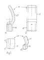
- the applicator 9 is now supplemented in the direction of the patient's body, namely around the non-hatched part 11. This has seen in a direction perpendicular to the longitudinal direction in FIG. 1 specified form and in the second direction perpendicular to the first and the L jossricntung in FIG. 2b illustrated form. In this case, the applicator 9 in FIG. 1 approximately in the correct proportion to the rest of the device shown in FIG. 2 but enlarged.
- FIG. 2a A longitudinal section through the front applicator part 11 is shown.
- a hollow receptacle is shown on the device-facing (proximal) side, which can serve for connection to the rest of the applicator, but does not play a significant role here.
- proximal proximal
- the flat-curved mold 13 starts from the pedestal with an inner radius of curvature of 5 mm, which gradually increases to the top of the flat-curved mold 13 up to 40 mm, the point itself being rounded with a radius of 2.5 mm is. This tip is tilted by 40 ° with respect to the impact direction.
- the radius of curvature on the outside of the flat-curved mold 13 is about 45 mm and the in Fig. 2a on average recognizable material thickness 5 mm. In the Fig. 2b visible width, however, is 20 mm over the entire area of the flat-curved mold 13, with only the corners are rounded.
- Fig. 2c shows a plan view, so a view in the direction of impact
- Fig. 2d a perspective view, wherein the concave side facing the rear left and the convex forward right. It can be seen that the tip lies in an area about 5 mm on both sides about the longitudinal axis (in the direction of impact).
- FIGS. 1 . 2a and 2d show that the front part 11 of the applicator 9 exactly a curvature with a concave side surface (in FIG. 2a to the left) and a convex (to the right), wherein the FIG. 2a also shows that in the local section plane the centers of curvature of the concavity and convexity are laterally adjacent to the applicator 9 and 11, namely, to the left. Furthermore, it can be seen that the curvature decreases from a proximal to a distal region.
Landscapes
- Health & Medical Sciences (AREA)
- Life Sciences & Earth Sciences (AREA)
- Surgery (AREA)
- Public Health (AREA)
- Veterinary Medicine (AREA)
- Animal Behavior & Ethology (AREA)
- General Health & Medical Sciences (AREA)
- Engineering & Computer Science (AREA)
- Orthopedic Medicine & Surgery (AREA)
- Biomedical Technology (AREA)
- Molecular Biology (AREA)
- Medical Informatics (AREA)
- Nuclear Medicine, Radiotherapy & Molecular Imaging (AREA)
- Heart & Thoracic Surgery (AREA)
- Vascular Medicine (AREA)
- Epidemiology (AREA)
- Rehabilitation Therapy (AREA)
- Pain & Pain Management (AREA)
- Physical Education & Sports Medicine (AREA)
- Mechanical Engineering (AREA)
- Surgical Instruments (AREA)
- Percussion Or Vibration Massage (AREA)
Abstract
Die Erfindung betrifft ein Gerät zur Behandlung des menschlichen oder tierischen Körpers mit Stößen, und einem dafür vorgesehenen Applikator 11, der eine gebogen-flache Form mit einer konkaven und einer konvexen Seitenfläche aufweist.The invention relates to a device for treating the human or animal body with bumps, and a dedicated applicator 11, which has a curved-flat shape with a concave and a convex side surface.
Description
Die vorliegende Erfindung bezieht sich auf ein Gerät zur Behandlung des menschlichen oder tierischen Körpers durch Ausüben von Stößen auf die Körperoberfläche. Im Folgenden wird zur Vereinfachung vom Körper eines Patienten gesprochen, der bevorzugt menschlich ist.The present invention relates to an apparatus for treating the human or animal body by exerting impacts on the body surface. For the sake of simplicity, the following is spoken of the body of a patient, who is preferably human.
Im Stand der Technik sind verschiedene Geräte des beschriebenen Grundtyps bekannt. Die
Der Schwerpunkt bei der Darstellung liegt in jedem Fall auf der durch die Kollision erzeugten Druckwelle, die mehr oder weniger einer eigentlichen Stoßwelle ähneln soll, wie sie klassische Lithotripsiegeräte z. B. mit piezoelektrischen oder induktiven Aktuatoren und Fokussierung auf einen Stein erzeugen. Solche Druckwellen können Anstiegsflanken mit einer Breite im Bereich weniger µs und einer Amplitude im niedrigen zweistelligen MPa-Bereich haben (z. B. 2 µs und 15 MPa gemessen 1 cm vor der Frontfläche). In dem zitierten Dokument wird hingegen betont, dass die physikalisch an sich unvermeidliche makroskopische Schwerpunktbewegung des Applikators möglichst klein gehalten werden soll, weil sie als störend angesehen wird.The focus in the presentation is in any case on the pressure wave generated by the collision, which should more or less resemble an actual shock wave, as they are classic lithotripsy devices z. B. with piezoelectric or inductive actuators and focus on a stone. Such pressure waves may have leading edges with a width in the range of a few μs and an amplitude in the low two-digit MPa range (eg 2 μs and 15 MPa measured 1 cm in front of the front surface). In the cited document, however, it is emphasized that the physically inherently unavoidable macroscopic center of gravity movement of the applicator should be kept as small as possible, because it is regarded as disturbing.
Als zweites Beispiel wird auf die
Die vorliegende Erfindung richtet sich allgemein auf Geräte dieses Bautyps, und zwar sowohl hinsichtlich der Anwendung von Druckwellen als auch hinsichtlich der Anwendung "makroskopischer Stöße" des Applikator auf die Körperoberfläche.The present invention is generally directed to devices of this type of construction, both in terms of the application of pressure waves and the application of "macroscopic shocks" of the applicator to the body surface.
Dabei liegt der Erfindung die Aufgabe zugrunde, ein solches Gerät hinsichtlich weitergehender Anwendungsmöglichkeiten weiterzubilden.The invention has the object to further develop such a device with regard to further applications.
Die Aufgabe wird gelöst durch ein Gerät nach Anspruch 1. Erfindungsgemäß ist dabei der Applikator gebogen-flach und weist entsprechend der Biegung eine konkave und eine entgegengesetzt angeordnete konvexe Seitenfläche auf. Diese Seitenflächen entsprechen sich in der Form insoweit, dass der Applikator dazwischen eine begrenzte Stärke hat, also "flach" ist, was auf einen Grenzwert von höchstens 1/3 der Applikatorerstreckung entlang der konkaven und der konvexen Seitenfläche konkretisiert wird.The object is achieved by a device according to claim 1. According to the invention, the applicator is bent-flat and has according to the bend on a concave and an oppositely disposed convex side surface. These side surfaces correspond in shape to the extent that the applicator has a limited thickness therebetween, that is to say "flat", which is substantiated to a limit of at most 1/3 of the applicator extension along the concave and the convex side surface.
Mit dieser Vergleichsangabe ist die Länge (im geraden Sinn, nicht gekrümmt der Biegung nachfolgend) des Applikators vom Anfang bis zum Ende der beschriebenen gebogenen Form gemeint. Wenn diese also zum Beispiel, wie im Ausführungsbeispiel, etwa um die 30 mm beträgt, so soll die Stärke zwischen der konvexen und der konkaven Seitenfläche höchstens 10 mm betragen, vorzugsweise höchstens 1/4 oder sogar höchstens 1/5 davon, also im Beispielsfall höchstens 7,5 oder höchstens 6 mm. Dickere Bereiche des Applikators sind natürlich nicht grundsätzlich ausgeschlossen, etwa in der Umgebung seines Montageabschnitts zur Verbindung mit dem restlichen Gerät. Sie rechnen aber nicht zu der erfindungsgemäßen Form und vorzugsweise sind sie auch nicht distal, sondern allenfalls proximal von dieser vorgesehen (die Begriffe proximal und distal beziehen sich auf die Stoßrichtung).By this comparison is meant the length (in a straight line, not curved in the curve below) of the applicator from the beginning to the end of the described curved shape. If, for example, this is about 30 mm, for example, as in the exemplary embodiment, the thickness between the convex and the concave side surface should be at most 10 mm, preferably at most 1/4 or even at most 1/5 thereof, ie at most in the example 7.5 or at most 6 mm. Of course, thicker areas of the applicator are not fundamentally excluded, for example in the vicinity of its mounting section to connect to the rest of the device. However, they do not reckon with the shape according to the invention and preferably they are not provided distally, but at most proximally thereof (the terms proximal and distal refer to the direction of impact).
Es hat sich herausgestellt, dass mit dieser flach gekrümmten Form die Arbeit des Therapeuten mit dem Gerät erleichtert wird. Insbesondere kann mit der gekrümmten Form hinter bestimmte Körperstrukturen "gegriffen" werden, ohne dass der Therapeut ein konventionelles Gerät dazu in unpraktischer Weise verkippt halten oder mit besonders hohem Druck auf die Körperoberfläche aufpressen müsste, um die Haut des Patienten ausreichend weit einzudrücken. Ein Beispiel ist der untere Rippenabschluss. Der Therapeut kann mit dem erfindungsgemäßen Applikator gewissermaßen um die untere Rippe herum greifen, wobei sich die konkave Seitenfläche an die Rippe anlegt, und behält dabei eine ergonomische und praktische Arbeitshaltung bei. Durch die begrenzte Stärke des Applikators muss dabei nur ein begrenzter Hautabschnitt eingedrückt und verschoben werden.It has been found that with this flat-curved shape the therapist's work with the device is facilitated. In particular, with the curved shape behind certain body structures can be "gripped" without the therapist would keep a conventional device tilted to unpractical way or would have to press with particularly high pressure on the body surface to depress the skin of the patient sufficiently far. An example is the lower rib end. With the applicator according to the invention, the therapist can, as it were, grip around the lower rib, with the concave side surface resting against the rib, while maintaining an ergonomic and practical working posture. Due to the limited strength of the applicator, only a limited portion of the skin has to be pressed in and pushed.
Ganz ähnlich bewährt sich die Erfindung bei der Behandlung von Muskeln innerhalb des Schulterblatts; auch hier kann der Therapeut mit dem Applikator um das Schulterblatt herumgreifen.Similarly, the invention has proven itself in the treatment of muscles within the scapula; Again, the therapist can grip around the shoulder blade with the applicator.
Außerdem eignet sich die konvexe Seite gleichzeitig als Schrägfläche für streichende Bewegungen auf der Körperoberfläche bei schräger Haltung des Geräts relativ zur Körperoberfläche. Dann greift sich das Gerät besser und kann in einer für den Therapeuten besser kontrollierbaren und bequemeren Weise über die Körperoberfläche geführt werden. Insbesondere können dabei Gewebepartien unter der Haut parallel massiert und/oder gewissermaßen vor dem Gerät hergeschoben werden, wobei sie gleichzeitig mit den Stößen und (in einem von Fall zu Fall unterschiedlichen Maß) Druckwellen beaufschlagt werden. Die konventionell bekannten Geräte mit mehr oder weniger flachen Frontflächen der Applikatoren sind dazu relativ schlecht geeignet, weil sie auf der Hautoberfläche nur bei mehr oder weniger senkrechter Stellung des Geräts relativ zur Körperoberfläche gehalten werden können.In addition, the convex side is at the same time as an inclined surface for stroking movements on the body surface with oblique attitude of the device relative to the body surface. Then the device gets better and can be guided over the body surface in a more controllable and comfortable way for the therapist. In particular, tissue sections under the skin can be massaged in parallel and / or pushed to a certain extent in front of the device, whereby they are acted on simultaneously with the shocks and (in a different case by case measure) pressure waves. The conventionally known devices with more or less flat front surfaces of the applicators are relatively poorly suited because they are on the skin surface can be held only at more or less vertical position of the device relative to the body surface.
Der Mechanismus zum Erzeugen der Stöße des Applikators ist in diesem Zusammenhang in unterschiedlichster Ausführung denkbar, insbesondere auch durch eine direkte Beaufschlagung des Applikators mittels eines elektromagnetischen Mechanismus oder auch eines Druckfluidpulses. Bevorzugt ist aber die aus den zitierten Dokumenten bereits bekannte Verwendung eines beschleunigten Projektils zur Kollision mit dem Applikator, womit relativ heftige und (im Sinn der Applikatorgeschwindigkeit) schnelle Stöße realisiert werden können und auch die gleichzeitige oder sogar schwerpunktmäßige Verwendung von Druckwellen möglich ist. Das Projektil wiederum lässt sich ebenfalls in unterschiedlicher Weise beschleunigen, insbesondere auch elektromagnetisch, wobei auch hier eine pneumatische Beaufschlagung des Projektils gemäß den zitierten Schriften bevorzugt ist.The mechanism for generating the shocks of the applicator is in this context conceivable in a wide variety of embodiments, in particular by direct application of the applicator by means of an electromagnetic mechanism or a pressure fluid pulse. However, the use of an accelerated projectile for collision with the applicator which is already known from the cited documents is preferred, whereby relatively fast and (in the sense of the applicator speed) rapid impacts can be realized and also the simultaneous or even main use of pressure waves is possible. The projectile, in turn, can also be accelerated in different ways, in particular also electromagnetically, in which case a pneumatic application of the projectile according to the cited documents is also preferred.
Der Begriff "Applikator" bezeichnet hier übrigens nicht zwingend ein einstückiges Teil. Es ist denkbar und anwendungsabhängig auch bevorzugt, dass das Projektil z. B. auf ein erstes Teil schlägt, das den Stoß und/oder die Druckwelle auf ein zweites Applikatorteil überträgt, das seinerseits mit der Haut des Patienten in Kontakt steht. Im Stand der Technik ist auch gelegentlich von einem Zwischenstück zwischen Applikator und Projektil die Rede; hier wird dann von einem mehrteiligen Applikator gesprochen, wobei die beiden Applikatorteile fest verbunden sein können, aber nicht sein müssen.Incidentally, the term "applicator" does not necessarily mean an integral part here. It is conceivable and application-dependent also preferred that the projectile z. B. strikes a first part that transmits the shock and / or the pressure wave to a second applicator, which in turn is in contact with the skin of the patient. The prior art also occasionally mentions an intermediate piece between the applicator and the projectile; Here is then spoken of a multi-part applicator, wherein the two Applikatorteile can be firmly connected, but need not be.
Wie eingangs bereits erwähnt, kann ein relativ großer Hub des Applikators durchaus gewünscht sein, wobei im vorliegenden Zusammenhang das Gerät vorzugsweise so ausgelegt ist, dass Hübe über 1 mm erreichbar sind, wie schon in der
Vorzugsweise weist der erfindungsgemäße Applikator genau den einen beschriebenen Krümmungsverlauf auf, also keinen weiteren mit anderem Krümmungssinn, etwa entgegengesetzt oder in einer deutlich abweichenden Ebene der Krümmung. Eine solche einfache Applikatorform ist nicht nur vorteilhaft hinsichtlich der Herstellbarkeit, sondern auch praktisch und komplikationsfrei in der Anwendung.Preferably, the applicator according to the invention has exactly the one curvature curve described, that is to say no other with a different curvature, approximately opposite or in a significantly different level of curvature. Such a simple applicator is not only advantageous in terms of manufacturability, but also practical and complication-free in the application.
Ferner liegen die konvexe und die konkave Seitenfläche vorzugsweise so, dass eine Schnittebene, in der sich die jeweilige Krümmung besonders ausgeprägt zeigt, die Stoßrichtung enthält und die auftretenden Krümmungsmittelpunkte in Bezug auf die Stoßrichtung seitlich neben dem Applikator liegen. In anderen Worten krümmt sich die Applikatorform so, dass die konvexe Seitenfläche in Bezug auf die Stoßrichtung zu einer Seite (und nicht in Bezug auf die Stoßrichtung nach vorne oder nach hinten) und die konkave Seitenfläche zu der entgegengesetzten Seite zeigt. Wenn man sich die Applikatorform in einer Schnittebene vereinfacht wie eine Banane vorstellt (vgl. Ausführungsbeispiel), um hier nur ein Beispiel zu nennen, dann liegt ein Ende dieser Banane proximal und das andere distal zum Gerät und liegt nicht etwa zum Beispiel die Mitte der Banane proximal zum Gerät und weisen die beiden Enden davon weg.Further, the convex and the concave side surface are preferably such that a sectional plane in which the respective curvature is particularly pronounced, contains the impact direction and the occurring centers of curvature with respect to the impact direction are located laterally next to the applicator. In other words, the applicator form bends so that the convex side surface is toward one side (and not forward or backward with respect to the impact direction) and the concave side surface toward the opposite side with respect to the impact direction. If one simplifies the applicator shape in a sectional plane as a banana imagines (see example), to give just one example, then one end of this banana is proximal and the other distal to the device and is not, for example, the center of the banana Proximal to the device and point the two ends away from it.
Ferner ist die Krümmung vorzugsweise im proximalen Bereich des Applikators stärker ausgeprägt als im distalen, vergrößern sich also die jeweiligen Krümmungsradien mit zunehmendem Abstand von dem Gerät, wozu ebenfalls auf das Ausführungsbeispiel verwiesen werden kann.Furthermore, the curvature is preferably more pronounced in the proximal region of the applicator than in the distal one, ie the respective radii of curvature increase with increasing distance from the device, to which reference may also be made to the exemplary embodiment.
Eine weitere bevorzugte Charakterisierung betrifft eine bisher noch nicht angesprochene Dimension, nämlich die Breite senkrecht zur Stoßrichtung und zu der Ebene, in der sich die Krümmung zeigt. Hier ist der Applikator mindestens so breit wie die angesprochene (dem Begriff "flach" zugrunde liegende) Stärke, vorzugsweise mindestens 1 1/2 mal so breit, oder sogar mindestens 2 mal, 2 1/2 mal oder sogar 3 mal so breit. Bevorzugt sind also "flach-breite" und nicht etwa stabförmige Geometrien (weswegen sich der obige Vergleich mit der Banane auf einen Schnitt bezieht).A further preferred characterization relates to a dimension not hitherto mentioned, namely the width perpendicular to the direction of impact and to the plane in which the curvature is shown. Here, the applicator is at least as wide as the addressed (term "shallow" underlying) thickness, preferably at least 1 1/2 times as wide, or even at least 2 times, 2 1/2 times, or even 3 times as wide. Preference is therefore given to "flat-wide" and not rod-like geometries (which is why the above comparison with the banana refers to a cut).
Schließlich ist der Applikator vor allem in seinem vorderen Bereich, konkret in der distalen Hälfte (in Bezug auf die Längserstreckung in Stoßrichtung) "kantenfrei" im Sinne von Mindestkrümmungsradien von 1,5 mm in zumindest einer Schnittebene, vorzugsweise der, in der sich die beschriebene Krümmung zeigt, und besonders bevorzugter Weise noch in einer zweiten Schnittebene senkrecht dazu, vgl. Ausführungsbeispiel.Finally, the applicator, especially in its front region, specifically in the distal half (with respect to the longitudinal extent in the direction of impact), is "edge-free" in the sense of minimum radii of curvature of 1.5 mm in at least one sectional plane, preferably that in which the described one Curvature shows, and particularly preferably still in a second sectional plane perpendicular thereto, cf. Embodiment.
Insgesamt ergeben sich für den Applikator hinsichtlich seines von dem übrigen Gerät freien (insbesondere daraus hervorstehenden) Teils folgende bevorzugte Dimensionen:Overall, for the applicator with respect to its free from the rest of the device (in particular protruding) part following dimensions:
Die Länge ist vorzugsweise größer als 10 mm, 20 mm, 30 mm oder sogar 35 mm und vorzugsweise kleiner als 100 mm, 90 mm, 80 mm, 70 mm, 65 mm oder sogar 60 mm. Beim Ausführungsbeispiel beträgt sie etwa 50 mm. Dabei beträgt die Länge des eigentlichen flach-gekrümmten Abschnitts beim Ausführungsbeispiel etwa 32 mm (in Stoßrichtung) und allgemein vorzugsweise mehr als 5 mm, 10 mm, 15 mm oder sogar 20 mm und vorzugsweise weniger als 60 mm, 50 mm, oder sogar 40 mm.The length is preferably greater than 10 mm, 20 mm, 30 mm or even 35 mm and preferably less than 100 mm, 90 mm, 80 mm, 70 mm, 65 mm or even 60 mm. In the embodiment, it is about 50 mm. In this case, the length of the actual flat-curved portion in the embodiment is about 32 mm (in the impact direction), and more preferably more than 5 mm, 10 mm, 15 mm or even 20 mm, and preferably less than 60 mm, 50 mm, or even 40 mm ,
Die Breite liegt vorzugsweise über 5 mm, 10 mm oder sogar 15 mm und andererseits vorzugsweise unter 80 mm, 60 mm, 40 mm oder sogar 30 mm und beträgt beim Ausführungsbeispiel 20 mm.The width is preferably above 5 mm, 10 mm or even 15 mm and on the other hand preferably below 80 mm, 60 mm, 40 mm or even 30 mm and in the embodiment 20 mm.
Die Stärke beträgt vorzugsweise mindestens 2 mm, 3 mm oder sogar 3,5 mm und vorzugsweise weniger als 10 mm, 9 mm, 8 mm oder sogar 7 mm und beim Ausführungsbeispiel 5 mm.The thickness is preferably at least 2 mm, 3 mm or even 3.5 mm and preferably less than 10 mm, 9 mm, 8 mm or even 7 mm and in the exemplary embodiment 5 mm.
Ferner sollte der vorderste Teil (distale Teil) in Bezug auf die Bewegungsrichtung einen Winkel von mindestens 20° oder sogar 25° und höchstens 80°, 70° oder sogar 60° haben. Beim Ausführungsbeispiel beträgt er im letzten Abschnitt etwa 40°.Further, the foremost part (distal part) should have an angle of at least 20 ° or even 25 ° and at most 80 °, 70 ° or even 60 ° with respect to the direction of movement. In the embodiment, it is in the last section about 40 °.
Vorzugsweise wird dieser Winkel über eine Krümmung erreicht, die sich ebenfalls vorzugsweise vom proximalen Abschnitt bis zum distalen Abschnitt verflacht (der Krümmungsradius nimmt also zu). Im distalen Bereich kann ein bevorzugter Krümmungsradius typischerweise über 15 mm, 20 mm oder sogar 25 mm und unter 80 mm, 75 mm, 70 mm, 65 mm, 60 mm oder sogar 55 mm liegen; beim Ausführungsbeispiel beträgt der Krümmungsradius dort 40 mm. Andererseits liegt er beim Ausführungsbeispiel im proximalen Abschnitt bei nur 5 mm und vergrößert sich von dort ausgehend.Preferably, this angle is achieved via a curvature, which also preferably flattens from the proximal section to the distal section (the radius of curvature thus increases). In the distal region, a preferred radius of curvature may typically be above 15mm, 20mm or even 25mm and below 80mm, 75mm, 70mm, 65mm, 60mm or even 55mm; In the embodiment, the radius of curvature is 40 mm there. On the other hand, it lies in the embodiment in the proximal section at only 5 mm and increases from there starting.
Schließlich liegt das distale Applikatorende im Bezug auf die Stoßrichtung vorzugsweise ungefähr mittig, und zwar vorzugweise innerhalb von 15 mm, oder sogar nur 5 mm um eine Mittellängsachse des Gerätes herum.Finally, the distal end of the applicator preferably lies approximately centrally with respect to the impact direction, preferably within 15 mm, or even only 5 mm, about a central longitudinal axis of the device.
Vorbekannte Applikatoren bestanden im Regelfall aus rostfreiem Stahl. Im vorliegenden Fall kommen grundsätzlich auch Metalle, so auch rostfreier Stahl, in Betracht. Daneben sind als metallische Materialien Aluminium und Titan zu nennen, wobei beide eine relativ geringe Massendichte haben und damit relativ leichte Applikatoren ermöglichen. Das kann den Vorteil haben, bei gegebener Geometrie eine stärkere Beschleunigung und damit auch größere Hubauslenkung des Applikators zu ermöglichen, was im vorliegenden Fall gewünscht sein kann. Titan zeichnet sich zudem durch eine besonders hohe mechanische Belastbarkeit aus, eignet sich also besonders für Anwendungen mit vergleichsweise hohen Projektilgeschwindigkeiten und/oder Projektilmassen, aber nicht nur hierfür. Oft ist auch die geringe Dichte und/oder gute physiologische Verträglichkeit ausschlaggebend. In Betracht kommen ferner Keramiken, vgl. Anmeldenummer 08 003 840.9 /
Im Folgenden wird die Erfindung auch anhand eines Ausführungsbeispiels näher erläutert, dessen einzelne Merkmale im Rahmen des geltenden Anspruchs 1 auch unabhängig voneinander und in anderen Kombinationen erfindungswesentlich sein können.
- Figur 1
- zeigt ein Druckwellengerät als erstes Ausführungsbeispiel der Erfindung mit einem in
Fig. 2 näher dargestellten Applikator. Figur 2- zeigt den Vorderteil des Applikators des Geräts aus
Fig. 1 in gleicher Blickrichtung wie inFig. 1 (aber aufrecht) und in einer Längsschnittdarstellung in Teildarstellung a, in einer Draufsicht mit um 90° um die Längsachse verdrehter Blickrichtung in Teildarstellung b, in einer weiteren Darstellung c in Längsrichtung des Geräts gesehen und schließlich in Teildarstellung d in perspektivischer Ansicht.
- FIG. 1
- shows a pressure wave device as a first embodiment of the invention with a in
Fig. 2 closer applicator. - FIG. 2
- shows the front part of the applicator of the device
Fig. 1 in the same direction as inFig. 1 (but upright) and in a longitudinal section in partial view a, in a plan view with 90 ° rotated about the longitudinal axis viewing direction in partial view b, seen in a further representation c in the longitudinal direction of the device and finally in partial view d in a perspective view.
Ein Rohrstück 1 bildet gemeinsam mit einer in der Anwendung körperabgewandten und mit dem Rohrstück 1 integrierten Zuluftkappe 2 und einer in der Anwendung körperzugewandten Applikatorkappe 3 ein Gehäuse. Die Zuluftkappe 2 enthält einen Druckluftanschluss 4 für eine pneumatische Versorgung. In an sich bekannter Weise ist an diesen Druckluftanschluss 4 über eine pneumatische Versorgungsleitung ein von einer Ansteuereinheit gesteuertes Ventil, insbesondere Magnetventil, angeschlossen, das in einem gleich bleibenden iterativen Takt zwischen etwa 1 Hz und 50 Hz Druckluftpulse über den Druckluftanschluss einkoppelt. Das Ventil ist nicht gezeigt und kann auch in dem dargestellten Gerät selbst eingebaut sein.A piece of pipe 1, together with a body facing away from the application and integrated with the pipe section 1 Zuluftkappe 2 and a body facing in the
Das Gerät ist im Übrigen als mit der Hand einer Bedienungsperson zu haltendes Gerät ausgebildet, das über die erwähnte Pneumatikleitung an eine nicht gezeigte Basisstation mit der Ansteuereinheit und dem Kompressor angeschlossen ist und auf den Patienten manuell aufgesetzt werden kann. Es eignet sich besonders für die Behandlung von Körperpartien hinter körpereigenen Hindernissen wie Rippen oder Schulterblättern.Incidentally, the apparatus is designed as a device to be held by the hand of an operator, which is connected via the aforementioned pneumatic line to a base station, not shown, with the drive unit and the compressor and can be placed manually on the patient. It is particularly suitable for the treatment of body parts behind the body's own obstacles such as ribs or shoulder blades.
In dem Gehäuse ist über einen Einsatz 5 ein Führungsrohr 6 gehalten, dessen bei der Anwendung körperfernes Ende in der Zuluftkappe 2 endet und dort mit dem Druckluftanschluss 4 kommuniziert. Das in der Anwendung körperseitige Ende des Führungsrohres 6 endet in einem Teil des Einsatzes 5, der in die Applikatorkappe 3 hineinragt, und zwar kurz vor dem dortigen Ende des Einsatzes 5 und einem Innenraum 7 in der Applikatorkappe 3.A
In dem Innenraum 7, der in eine in der Anwendung körperseitige Applikatoröffnung übergeht, ist ein erster und in
Der Applikator 9 weist als zweiten Teil das nicht schraffierte Element 11 auf, das den eigentlichen auf die Haut aufzusetzenden Applikator bildet. Der Applikator 9 ist durch Abschrauben der Applikatorkappe 3 austauschbar.The
In dem angrenzenden Bereich des Führungsrohres 6 ist ein in
Die Rückbewegung des Projektils 13 erfolgt zusätzlich zu einem Zurückprallen nach der Kollision durch ein Rückströmen der Luft aus einer das Führungsrohr 6 innerhalb des Einsatzes 5 umgebenden Staukammer 14. In diese wird die Luft bei der Beschleunigung des Projektils 13 in Richtung zu dem Prallkörper 9 verdrängt und damit dort komprimiert. Wenn das Magnetventil den Druck wegschaltet und gleichzeitig den Raum hinter dem Projektil entlüftet, wird das Projektil 13 damit in die Ausgangsstellung zurückbewegt. Dies kann natürlich auch durch eine zusätzliche oder alternative Druckbeaufschlagung der Staukammer 14 oder eines anderen Luftvolumens körperseitig von dem Projektil 13 erfolgen. Das in der Anwendung körperferne Ende des Führungsrohres 6 endet in einem Magnethalter für das Projektil 13.The return movement of the projectile 13 is carried out in addition to a rebounding after the collision by a backflow of air from a
Wenn man sich den schraffierten Teil 16 des Applikators 9 in
In
Die flach gekrümmte Form 13 startet von dem Sockel ausgehend mit einem inneren Krümmungsradius von 5 mm, der sich bis zu der Spitze der flach-gekrümmten Form 13 allmählich vergrößert bis auf 40 mm, wobei die Spitze selbst mit einem Radius von 2,5 mm verrundet ist. Diese Spitze ist gegenüber der Stoßrichtung um 40° verkippt. Der Krümmungsradius an der Außenseite der flach-gekrümmten Form 13 beträgt etwa 45 mm und die in
Die
Mit einem solchen Vorderteil 11 des Applikators kann die behandelnde Person um bestimmte Körperstrukturen wie z. B. Rippen und Schulterblätter herumgreifen und ist damit für bestimmte Anwendungsfälle besonders praktisch ausgestattet.With such a
Claims (12)
Priority Applications (3)
| Application Number | Priority Date | Filing Date | Title |
|---|---|---|---|
| EP14186613.7A EP3000418B1 (en) | 2014-09-26 | 2014-09-26 | Device for treatment of the human or animal body with mechanical impacts |
| US14/865,847 US20160089297A1 (en) | 2014-09-26 | 2015-09-25 | Apparatus for treating the human or animal body with mechanical strokes |
| CN201510859495.8A CN105534568B (en) | 2014-09-26 | 2015-09-28 | Utilize the equipment of mechanical shock disposition human or animal's body |
Applications Claiming Priority (1)
| Application Number | Priority Date | Filing Date | Title |
|---|---|---|---|
| EP14186613.7A EP3000418B1 (en) | 2014-09-26 | 2014-09-26 | Device for treatment of the human or animal body with mechanical impacts |
Publications (2)
| Publication Number | Publication Date |
|---|---|
| EP3000418A1 true EP3000418A1 (en) | 2016-03-30 |
| EP3000418B1 EP3000418B1 (en) | 2016-11-09 |
Family
ID=51619045
Family Applications (1)
| Application Number | Title | Priority Date | Filing Date |
|---|---|---|---|
| EP14186613.7A Active EP3000418B1 (en) | 2014-09-26 | 2014-09-26 | Device for treatment of the human or animal body with mechanical impacts |
Country Status (3)
| Country | Link |
|---|---|
| US (1) | US20160089297A1 (en) |
| EP (1) | EP3000418B1 (en) |
| CN (1) | CN105534568B (en) |
Families Citing this family (4)
| Publication number | Priority date | Publication date | Assignee | Title |
|---|---|---|---|---|
| US11484724B2 (en) | 2015-09-30 | 2022-11-01 | Btl Medical Solutions A.S. | Methods and devices for tissue treatment using mechanical stimulation and electromagnetic field |
| CN107811832A (en) * | 2017-11-28 | 2018-03-20 | 广东美的安川服务机器人有限公司 | Shock wave treatment device |
| US11779514B2 (en) * | 2019-09-02 | 2023-10-10 | Moon Pool Llc | Personal use extracorporeal low intensity acoustic or shock wave mechanical tip and methods of use |
| US20210283000A1 (en) * | 2020-03-14 | 2021-09-16 | Kusha Karvandi | Apparatus and method for relieving tightness in the hip flexor muscles |
Citations (7)
| Publication number | Priority date | Publication date | Assignee | Title |
|---|---|---|---|---|
| DE19725477A1 (en) * | 1997-06-17 | 1998-12-24 | Ferton Holding | Medical instrument for the treatment of biological tissue |
| US20020082532A1 (en) * | 2000-12-26 | 2002-06-27 | Tucek Kevin B. | Chiropractic adjustor apparatus having housing configured for enhanced heat dissipation and symmetrical force-transmitting shaft support |
| US20030009116A1 (en) * | 2001-07-03 | 2003-01-09 | Luettgen Harold A. | Vibrating personal massager |
| DE202004011323U1 (en) | 2004-07-09 | 2005-09-22 | Storz Medical Ag | Instrument for applying vibrations to the human body |
| US20060064864A1 (en) * | 2004-09-27 | 2006-03-30 | Ferton Holding S.A. | Device and method for removing tooth applications such as brackets |
| EP2095843A1 (en) | 2008-02-29 | 2009-09-02 | Storz Medical Ag | Device for treating biological body substances with mechanical pressure waves |
| US20110054367A1 (en) | 2004-07-09 | 2011-03-03 | Manfred Schulz | Instrument For Applying Vibrations To The Human Body |
Family Cites Families (12)
| Publication number | Priority date | Publication date | Assignee | Title |
|---|---|---|---|---|
| US2134133A (en) * | 1936-06-05 | 1938-10-25 | Joseph N Landau | Massage device |
| US5239985A (en) * | 1987-04-28 | 1993-08-31 | Medicuba | Electrode to destroy renal stones |
| CN1062650A (en) * | 1990-12-29 | 1992-07-15 | 中国科学院电工研究所 | Discharge motor of external shock wave lithotriptor |
| US5885301A (en) * | 1993-03-26 | 1999-03-23 | Orthosonics, Ltd. | Tool bit for use in ultrasonic removal of plastics embedment of an osteal prostheses |
| US6010467A (en) * | 1997-08-22 | 2000-01-04 | William Arthur Smith | Back trigger-point instrument |
| US6856199B2 (en) * | 2000-10-10 | 2005-02-15 | California Institute Of Technology | Reconfigurable distributed active transformers |
| GB0116676D0 (en) * | 2001-07-07 | 2001-08-29 | Eaton Corp | Synchronizer |
| WO2010110823A1 (en) * | 2009-03-27 | 2010-09-30 | Bing Innovations, Llc | Apparatus and method for reducing pain during skin puncturing procedures |
| CN1329007C (en) * | 2004-12-28 | 2007-08-01 | 王华林 | Air passage control system of tee joint vacuum valve in use for stone crusher of ballistic curve |
| WO2013071170A1 (en) * | 2011-11-10 | 2013-05-16 | Zadeh Homayoun H | Improved surgical tips for piezoelectric bone surgery |
| US9474682B2 (en) * | 2012-09-05 | 2016-10-25 | Star Generation Limited Taiwan Branch | Light guide type pain reliever |
| CN105407855A (en) * | 2013-06-04 | 2016-03-16 | 西格玛仪器控股有限责任公司 | Diagnostic and therapeutic treatment device, and related systems and methods of utilizing such a device |
-
2014
- 2014-09-26 EP EP14186613.7A patent/EP3000418B1/en active Active
-
2015
- 2015-09-25 US US14/865,847 patent/US20160089297A1/en not_active Abandoned
- 2015-09-28 CN CN201510859495.8A patent/CN105534568B/en active Active
Patent Citations (8)
| Publication number | Priority date | Publication date | Assignee | Title |
|---|---|---|---|---|
| DE19725477A1 (en) * | 1997-06-17 | 1998-12-24 | Ferton Holding | Medical instrument for the treatment of biological tissue |
| DE19725477C2 (en) | 1997-06-17 | 1999-10-21 | Ferton Holding | Medical instrument for the treatment of biological tissue |
| US20020082532A1 (en) * | 2000-12-26 | 2002-06-27 | Tucek Kevin B. | Chiropractic adjustor apparatus having housing configured for enhanced heat dissipation and symmetrical force-transmitting shaft support |
| US20030009116A1 (en) * | 2001-07-03 | 2003-01-09 | Luettgen Harold A. | Vibrating personal massager |
| DE202004011323U1 (en) | 2004-07-09 | 2005-09-22 | Storz Medical Ag | Instrument for applying vibrations to the human body |
| US20110054367A1 (en) | 2004-07-09 | 2011-03-03 | Manfred Schulz | Instrument For Applying Vibrations To The Human Body |
| US20060064864A1 (en) * | 2004-09-27 | 2006-03-30 | Ferton Holding S.A. | Device and method for removing tooth applications such as brackets |
| EP2095843A1 (en) | 2008-02-29 | 2009-09-02 | Storz Medical Ag | Device for treating biological body substances with mechanical pressure waves |
Also Published As
| Publication number | Publication date |
|---|---|
| CN105534568B (en) | 2019-09-03 |
| CN105534568A (en) | 2016-05-04 |
| US20160089297A1 (en) | 2016-03-31 |
| EP3000418B1 (en) | 2016-11-09 |
Similar Documents
| Publication | Publication Date | Title |
|---|---|---|
| EP3388003B1 (en) | Pressure wave device | |
| DE69030262T2 (en) | SURGICAL INSTRUMENT WITH CONVERTER FOR INPUT PERFORMANCE | |
| EP3000418B1 (en) | Device for treatment of the human or animal body with mechanical impacts | |
| DE69019381T2 (en) | Thin support plate for pliers. | |
| EP2213273B1 (en) | Setting parameters for a device for shock wave treatment | |
| EP2181730B1 (en) | Instrument for producing shock wave-like pressure waves for treating biological tissue | |
| EP2996585B1 (en) | Surgical instrument | |
| EP2529679B1 (en) | Acoustic dampening casing for application to a pressure wave device | |
| DE3542667A1 (en) | Device for the removal of body stones | |
| DE102010050337A1 (en) | Device for cutting and suctioning tissue | |
| DE102015103750A1 (en) | Syringe with a first and second syringe barrel | |
| DE69936509T2 (en) | BUMPERED BIOPSY DEVICE | |
| DE202014007692U1 (en) | Device for treating the human or animal body with mechanical shocks | |
| DE202014007693U1 (en) | Device for treating the human or animal body with mechanical shocks | |
| WO2020057700A2 (en) | Intraocular surgical tool | |
| CH704384A2 (en) | Surgical cutting instrument has cutting head, which is arranged in cannula for carrying out lifting movement, where cannula has cannula-opening at its periphery | |
| EP3000419B1 (en) | Device for treatment of the human or animal body with mechanical impacts | |
| DE202014010463U1 (en) | Device for treating the human or animal body with mechanical shocks | |
| EP3518800B1 (en) | Striking tool for treatment of bones in hip operations | |
| EP3624709A1 (en) | Fecal impaction removal device | |
| DE202017001951U1 (en) | Pressure wave machine | |
| DE202014010461U1 (en) | Device for treating the human or animal body with mechanical shocks | |
| DE10225709B4 (en) | Bellows for coupling a source of acoustic waves to a living being | |
| DE202021100954U1 (en) | Device for treating the human or animal body with mechanical shocks | |
| DE102021104566A1 (en) | Device for treating the human or animal body with mechanical impact |
Legal Events
| Date | Code | Title | Description |
|---|---|---|---|
| PUAI | Public reference made under article 153(3) epc to a published international application that has entered the european phase |
Free format text: ORIGINAL CODE: 0009012 |
|
| 17P | Request for examination filed |
Effective date: 20160121 |
|
| AK | Designated contracting states |
Kind code of ref document: A1 Designated state(s): AL AT BE BG CH CY CZ DE DK EE ES FI FR GB GR HR HU IE IS IT LI LT LU LV MC MK MT NL NO PL PT RO RS SE SI SK SM TR |
|
| AX | Request for extension of the european patent |
Extension state: BA ME |
|
| GRAP | Despatch of communication of intention to grant a patent |
Free format text: ORIGINAL CODE: EPIDOSNIGR1 |
|
| INTG | Intention to grant announced |
Effective date: 20160614 |
|
| GRAS | Grant fee paid |
Free format text: ORIGINAL CODE: EPIDOSNIGR3 |
|
| GRAA | (expected) grant |
Free format text: ORIGINAL CODE: 0009210 |
|
| AK | Designated contracting states |
Kind code of ref document: B1 Designated state(s): AL AT BE BG CH CY CZ DE DK EE ES FI FR GB GR HR HU IE IS IT LI LT LU LV MC MK MT NL NO PL PT RO RS SE SI SK SM TR |
|
| REG | Reference to a national code |
Ref country code: GB Ref legal event code: FG4D Free format text: NOT ENGLISH |
|
| REG | Reference to a national code |
Ref country code: AT Ref legal event code: REF Ref document number: 843142 Country of ref document: AT Kind code of ref document: T Effective date: 20161115 Ref country code: CH Ref legal event code: EP |
|
| REG | Reference to a national code |
Ref country code: IE Ref legal event code: FG4D Free format text: LANGUAGE OF EP DOCUMENT: GERMAN |
|
| REG | Reference to a national code |
Ref country code: DE Ref legal event code: R096 Ref document number: 502014001915 Country of ref document: DE |
|
| PG25 | Lapsed in a contracting state [announced via postgrant information from national office to epo] |
Ref country code: LV Free format text: LAPSE BECAUSE OF FAILURE TO SUBMIT A TRANSLATION OF THE DESCRIPTION OR TO PAY THE FEE WITHIN THE PRESCRIBED TIME-LIMIT Effective date: 20161109 |
|
| REG | Reference to a national code |
Ref country code: LT Ref legal event code: MG4D |
|
| REG | Reference to a national code |
Ref country code: NL Ref legal event code: MP Effective date: 20161109 |
|
| PG25 | Lapsed in a contracting state [announced via postgrant information from national office to epo] |
Ref country code: NO Free format text: LAPSE BECAUSE OF FAILURE TO SUBMIT A TRANSLATION OF THE DESCRIPTION OR TO PAY THE FEE WITHIN THE PRESCRIBED TIME-LIMIT Effective date: 20170209 Ref country code: GR Free format text: LAPSE BECAUSE OF FAILURE TO SUBMIT A TRANSLATION OF THE DESCRIPTION OR TO PAY THE FEE WITHIN THE PRESCRIBED TIME-LIMIT Effective date: 20170210 Ref country code: NL Free format text: LAPSE BECAUSE OF FAILURE TO SUBMIT A TRANSLATION OF THE DESCRIPTION OR TO PAY THE FEE WITHIN THE PRESCRIBED TIME-LIMIT Effective date: 20161109 Ref country code: SE Free format text: LAPSE BECAUSE OF FAILURE TO SUBMIT A TRANSLATION OF THE DESCRIPTION OR TO PAY THE FEE WITHIN THE PRESCRIBED TIME-LIMIT Effective date: 20161109 Ref country code: LT Free format text: LAPSE BECAUSE OF FAILURE TO SUBMIT A TRANSLATION OF THE DESCRIPTION OR TO PAY THE FEE WITHIN THE PRESCRIBED TIME-LIMIT Effective date: 20161109 |
|
| PG25 | Lapsed in a contracting state [announced via postgrant information from national office to epo] |
Ref country code: ES Free format text: LAPSE BECAUSE OF FAILURE TO SUBMIT A TRANSLATION OF THE DESCRIPTION OR TO PAY THE FEE WITHIN THE PRESCRIBED TIME-LIMIT Effective date: 20161109 Ref country code: HR Free format text: LAPSE BECAUSE OF FAILURE TO SUBMIT A TRANSLATION OF THE DESCRIPTION OR TO PAY THE FEE WITHIN THE PRESCRIBED TIME-LIMIT Effective date: 20161109 Ref country code: IS Free format text: LAPSE BECAUSE OF FAILURE TO SUBMIT A TRANSLATION OF THE DESCRIPTION OR TO PAY THE FEE WITHIN THE PRESCRIBED TIME-LIMIT Effective date: 20170309 Ref country code: RS Free format text: LAPSE BECAUSE OF FAILURE TO SUBMIT A TRANSLATION OF THE DESCRIPTION OR TO PAY THE FEE WITHIN THE PRESCRIBED TIME-LIMIT Effective date: 20161109 Ref country code: FI Free format text: LAPSE BECAUSE OF FAILURE TO SUBMIT A TRANSLATION OF THE DESCRIPTION OR TO PAY THE FEE WITHIN THE PRESCRIBED TIME-LIMIT Effective date: 20161109 Ref country code: PT Free format text: LAPSE BECAUSE OF FAILURE TO SUBMIT A TRANSLATION OF THE DESCRIPTION OR TO PAY THE FEE WITHIN THE PRESCRIBED TIME-LIMIT Effective date: 20170309 Ref country code: PL Free format text: LAPSE BECAUSE OF FAILURE TO SUBMIT A TRANSLATION OF THE DESCRIPTION OR TO PAY THE FEE WITHIN THE PRESCRIBED TIME-LIMIT Effective date: 20161109 |
|
| PG25 | Lapsed in a contracting state [announced via postgrant information from national office to epo] |
Ref country code: RO Free format text: LAPSE BECAUSE OF FAILURE TO SUBMIT A TRANSLATION OF THE DESCRIPTION OR TO PAY THE FEE WITHIN THE PRESCRIBED TIME-LIMIT Effective date: 20161109 Ref country code: CZ Free format text: LAPSE BECAUSE OF FAILURE TO SUBMIT A TRANSLATION OF THE DESCRIPTION OR TO PAY THE FEE WITHIN THE PRESCRIBED TIME-LIMIT Effective date: 20161109 Ref country code: EE Free format text: LAPSE BECAUSE OF FAILURE TO SUBMIT A TRANSLATION OF THE DESCRIPTION OR TO PAY THE FEE WITHIN THE PRESCRIBED TIME-LIMIT Effective date: 20161109 Ref country code: DK Free format text: LAPSE BECAUSE OF FAILURE TO SUBMIT A TRANSLATION OF THE DESCRIPTION OR TO PAY THE FEE WITHIN THE PRESCRIBED TIME-LIMIT Effective date: 20161109 Ref country code: SK Free format text: LAPSE BECAUSE OF FAILURE TO SUBMIT A TRANSLATION OF THE DESCRIPTION OR TO PAY THE FEE WITHIN THE PRESCRIBED TIME-LIMIT Effective date: 20161109 |
|
| REG | Reference to a national code |
Ref country code: DE Ref legal event code: R097 Ref document number: 502014001915 Country of ref document: DE |
|
| PG25 | Lapsed in a contracting state [announced via postgrant information from national office to epo] |
Ref country code: SM Free format text: LAPSE BECAUSE OF FAILURE TO SUBMIT A TRANSLATION OF THE DESCRIPTION OR TO PAY THE FEE WITHIN THE PRESCRIBED TIME-LIMIT Effective date: 20161109 Ref country code: BG Free format text: LAPSE BECAUSE OF FAILURE TO SUBMIT A TRANSLATION OF THE DESCRIPTION OR TO PAY THE FEE WITHIN THE PRESCRIBED TIME-LIMIT Effective date: 20170209 |
|
| PLBE | No opposition filed within time limit |
Free format text: ORIGINAL CODE: 0009261 |
|
| STAA | Information on the status of an ep patent application or granted ep patent |
Free format text: STATUS: NO OPPOSITION FILED WITHIN TIME LIMIT |
|
| REG | Reference to a national code |
Ref country code: FR Ref legal event code: PLFP Year of fee payment: 4 |
|
| 26N | No opposition filed |
Effective date: 20170810 |
|
| PG25 | Lapsed in a contracting state [announced via postgrant information from national office to epo] |
Ref country code: SI Free format text: LAPSE BECAUSE OF FAILURE TO SUBMIT A TRANSLATION OF THE DESCRIPTION OR TO PAY THE FEE WITHIN THE PRESCRIBED TIME-LIMIT Effective date: 20161109 |
|
| REG | Reference to a national code |
Ref country code: CH Ref legal event code: PL |
|
| PG25 | Lapsed in a contracting state [announced via postgrant information from national office to epo] |
Ref country code: MC Free format text: LAPSE BECAUSE OF FAILURE TO SUBMIT A TRANSLATION OF THE DESCRIPTION OR TO PAY THE FEE WITHIN THE PRESCRIBED TIME-LIMIT Effective date: 20161109 |
|
| REG | Reference to a national code |
Ref country code: IE Ref legal event code: MM4A |
|
| REG | Reference to a national code |
Ref country code: BE Ref legal event code: MM Effective date: 20170930 |
|
| PG25 | Lapsed in a contracting state [announced via postgrant information from national office to epo] |
Ref country code: LU Free format text: LAPSE BECAUSE OF NON-PAYMENT OF DUE FEES Effective date: 20170926 |
|
| PG25 | Lapsed in a contracting state [announced via postgrant information from national office to epo] |
Ref country code: LI Free format text: LAPSE BECAUSE OF NON-PAYMENT OF DUE FEES Effective date: 20170930 Ref country code: IE Free format text: LAPSE BECAUSE OF NON-PAYMENT OF DUE FEES Effective date: 20170926 Ref country code: CH Free format text: LAPSE BECAUSE OF NON-PAYMENT OF DUE FEES Effective date: 20170930 |
|
| PG25 | Lapsed in a contracting state [announced via postgrant information from national office to epo] |
Ref country code: BE Free format text: LAPSE BECAUSE OF NON-PAYMENT OF DUE FEES Effective date: 20170930 |
|
| REG | Reference to a national code |
Ref country code: FR Ref legal event code: PLFP Year of fee payment: 5 |
|
| PG25 | Lapsed in a contracting state [announced via postgrant information from national office to epo] |
Ref country code: MT Free format text: LAPSE BECAUSE OF FAILURE TO SUBMIT A TRANSLATION OF THE DESCRIPTION OR TO PAY THE FEE WITHIN THE PRESCRIBED TIME-LIMIT Effective date: 20161109 |
|
| PG25 | Lapsed in a contracting state [announced via postgrant information from national office to epo] |
Ref country code: HU Free format text: LAPSE BECAUSE OF FAILURE TO SUBMIT A TRANSLATION OF THE DESCRIPTION OR TO PAY THE FEE WITHIN THE PRESCRIBED TIME-LIMIT; INVALID AB INITIO Effective date: 20140926 |
|
| PG25 | Lapsed in a contracting state [announced via postgrant information from national office to epo] |
Ref country code: CY Free format text: LAPSE BECAUSE OF FAILURE TO SUBMIT A TRANSLATION OF THE DESCRIPTION OR TO PAY THE FEE WITHIN THE PRESCRIBED TIME-LIMIT Effective date: 20161109 |
|
| PG25 | Lapsed in a contracting state [announced via postgrant information from national office to epo] |
Ref country code: MK Free format text: LAPSE BECAUSE OF FAILURE TO SUBMIT A TRANSLATION OF THE DESCRIPTION OR TO PAY THE FEE WITHIN THE PRESCRIBED TIME-LIMIT Effective date: 20161109 |
|
| PG25 | Lapsed in a contracting state [announced via postgrant information from national office to epo] |
Ref country code: TR Free format text: LAPSE BECAUSE OF FAILURE TO SUBMIT A TRANSLATION OF THE DESCRIPTION OR TO PAY THE FEE WITHIN THE PRESCRIBED TIME-LIMIT Effective date: 20161109 |
|
| PG25 | Lapsed in a contracting state [announced via postgrant information from national office to epo] |
Ref country code: AL Free format text: LAPSE BECAUSE OF FAILURE TO SUBMIT A TRANSLATION OF THE DESCRIPTION OR TO PAY THE FEE WITHIN THE PRESCRIBED TIME-LIMIT Effective date: 20161109 |
|
| REG | Reference to a national code |
Ref country code: AT Ref legal event code: MM01 Ref document number: 843142 Country of ref document: AT Kind code of ref document: T Effective date: 20190926 |
|
| PG25 | Lapsed in a contracting state [announced via postgrant information from national office to epo] |
Ref country code: AT Free format text: LAPSE BECAUSE OF NON-PAYMENT OF DUE FEES Effective date: 20190926 |
|
| P01 | Opt-out of the competence of the unified patent court (upc) registered |
Effective date: 20230504 |
|
| PGFP | Annual fee paid to national office [announced via postgrant information from national office to epo] |
Ref country code: GB Payment date: 20230920 Year of fee payment: 10 |
|
| PGFP | Annual fee paid to national office [announced via postgrant information from national office to epo] |
Ref country code: FR Payment date: 20230922 Year of fee payment: 10 Ref country code: DE Payment date: 20230919 Year of fee payment: 10 |
|
| PGFP | Annual fee paid to national office [announced via postgrant information from national office to epo] |
Ref country code: IT Payment date: 20230922 Year of fee payment: 10 |