EP3000419B1 - Device for treatment of the human or animal body with mechanical impacts - Google Patents
Device for treatment of the human or animal body with mechanical impacts Download PDFInfo
- Publication number
- EP3000419B1 EP3000419B1 EP14186623.6A EP14186623A EP3000419B1 EP 3000419 B1 EP3000419 B1 EP 3000419B1 EP 14186623 A EP14186623 A EP 14186623A EP 3000419 B1 EP3000419 B1 EP 3000419B1
- Authority
- EP
- European Patent Office
- Prior art keywords
- applicator
- front area
- projectile
- area portion
- front surface
- Prior art date
- Legal status (The legal status is an assumption and is not a legal conclusion. Google has not performed a legal analysis and makes no representation as to the accuracy of the status listed.)
- Active
Links
- 241001465754 Metazoa Species 0.000 title claims description 4
- 238000011282 treatment Methods 0.000 title description 2
- RTAQQCXQSZGOHL-UHFFFAOYSA-N Titanium Chemical compound [Ti] RTAQQCXQSZGOHL-UHFFFAOYSA-N 0.000 claims description 5
- 239000010936 titanium Substances 0.000 claims description 5
- 229910052719 titanium Inorganic materials 0.000 claims description 5
- 229910052782 aluminium Inorganic materials 0.000 claims description 3
- XAGFODPZIPBFFR-UHFFFAOYSA-N aluminium Chemical compound [Al] XAGFODPZIPBFFR-UHFFFAOYSA-N 0.000 claims description 3
- 239000000919 ceramic Substances 0.000 claims description 3
- 229910052751 metal Inorganic materials 0.000 claims description 3
- 239000002184 metal Substances 0.000 claims description 3
- 239000002023 wood Substances 0.000 claims description 3
- 239000004411 aluminium Substances 0.000 claims 1
- 229920002994 synthetic fiber Polymers 0.000 claims 1
- 230000035939 shock Effects 0.000 description 8
- 239000004033 plastic Substances 0.000 description 6
- 229920003023 plastic Polymers 0.000 description 6
- 239000000463 material Substances 0.000 description 4
- 229910001220 stainless steel Inorganic materials 0.000 description 3
- 239000010935 stainless steel Substances 0.000 description 3
- 230000001133 acceleration Effects 0.000 description 2
- 230000008878 coupling Effects 0.000 description 2
- 238000010168 coupling process Methods 0.000 description 2
- 238000005859 coupling reaction Methods 0.000 description 2
- 230000012447 hatching Effects 0.000 description 2
- 150000002739 metals Chemical class 0.000 description 2
- 210000001519 tissue Anatomy 0.000 description 2
- 230000007704 transition Effects 0.000 description 2
- 208000000913 Kidney Calculi Diseases 0.000 description 1
- 206010029148 Nephrolithiasis Diseases 0.000 description 1
- 208000027418 Wounds and injury Diseases 0.000 description 1
- DHKHKXVYLBGOIT-UHFFFAOYSA-N acetaldehyde Diethyl Acetal Natural products CCOC(C)OCC DHKHKXVYLBGOIT-UHFFFAOYSA-N 0.000 description 1
- 125000002777 acetyl group Chemical class [H]C([H])([H])C(*)=O 0.000 description 1
- 238000009232 chiropractic Methods 0.000 description 1
- 239000012141 concentrate Substances 0.000 description 1
- 238000010276 construction Methods 0.000 description 1
- 230000006378 damage Effects 0.000 description 1
- 230000001419 dependent effect Effects 0.000 description 1
- 229920001971 elastomer Polymers 0.000 description 1
- 239000000806 elastomer Substances 0.000 description 1
- 210000003195 fascia Anatomy 0.000 description 1
- 230000002349 favourable effect Effects 0.000 description 1
- 239000012530 fluid Substances 0.000 description 1
- 230000005484 gravity Effects 0.000 description 1
- 230000001939 inductive effect Effects 0.000 description 1
- 208000014674 injury Diseases 0.000 description 1
- 230000007794 irritation Effects 0.000 description 1
- 239000007769 metal material Substances 0.000 description 1
- 210000003205 muscle Anatomy 0.000 description 1
- 239000000523 sample Substances 0.000 description 1
- 210000004872 soft tissue Anatomy 0.000 description 1
- -1 stainless steel Chemical class 0.000 description 1
- 239000004575 stone Substances 0.000 description 1
- 239000000725 suspension Substances 0.000 description 1
- 230000001225 therapeutic effect Effects 0.000 description 1
- 229920001169 thermoplastic Polymers 0.000 description 1
- 239000004416 thermosoftening plastic Substances 0.000 description 1
- 230000001960 triggered effect Effects 0.000 description 1
- 238000013022 venting Methods 0.000 description 1
Images


Classifications
-
- A—HUMAN NECESSITIES
- A61—MEDICAL OR VETERINARY SCIENCE; HYGIENE
- A61B—DIAGNOSIS; SURGERY; IDENTIFICATION
- A61B17/00—Surgical instruments, devices or methods, e.g. tourniquets
- A61B17/22—Implements for squeezing-off ulcers or the like on the inside of inner organs of the body; Implements for scraping-out cavities of body organs, e.g. bones; Calculus removers; Calculus smashing apparatus; Apparatus for removing obstructions in blood vessels, not otherwise provided for
- A61B17/225—Implements for squeezing-off ulcers or the like on the inside of inner organs of the body; Implements for scraping-out cavities of body organs, e.g. bones; Calculus removers; Calculus smashing apparatus; Apparatus for removing obstructions in blood vessels, not otherwise provided for for extracorporeal shock wave lithotripsy [ESWL], e.g. by using ultrasonic waves
- A61B17/2251—Implements for squeezing-off ulcers or the like on the inside of inner organs of the body; Implements for scraping-out cavities of body organs, e.g. bones; Calculus removers; Calculus smashing apparatus; Apparatus for removing obstructions in blood vessels, not otherwise provided for for extracorporeal shock wave lithotripsy [ESWL], e.g. by using ultrasonic waves characterised by coupling elements between the apparatus, e.g. shock wave apparatus or locating means, and the patient, e.g. details of bags, pressure control of bag on patient
-
- A—HUMAN NECESSITIES
- A61—MEDICAL OR VETERINARY SCIENCE; HYGIENE
- A61B—DIAGNOSIS; SURGERY; IDENTIFICATION
- A61B17/00—Surgical instruments, devices or methods, e.g. tourniquets
- A61B17/22—Implements for squeezing-off ulcers or the like on the inside of inner organs of the body; Implements for scraping-out cavities of body organs, e.g. bones; Calculus removers; Calculus smashing apparatus; Apparatus for removing obstructions in blood vessels, not otherwise provided for
- A61B17/22004—Implements for squeezing-off ulcers or the like on the inside of inner organs of the body; Implements for scraping-out cavities of body organs, e.g. bones; Calculus removers; Calculus smashing apparatus; Apparatus for removing obstructions in blood vessels, not otherwise provided for using mechanical vibrations, e.g. ultrasonic shock waves
-
- A—HUMAN NECESSITIES
- A61—MEDICAL OR VETERINARY SCIENCE; HYGIENE
- A61H—PHYSICAL THERAPY APPARATUS, e.g. DEVICES FOR LOCATING OR STIMULATING REFLEX POINTS IN THE BODY; ARTIFICIAL RESPIRATION; MASSAGE; BATHING DEVICES FOR SPECIAL THERAPEUTIC OR HYGIENIC PURPOSES OR SPECIFIC PARTS OF THE BODY
- A61H23/00—Percussion or vibration massage, e.g. using supersonic vibration; Suction-vibration massage; Massage with moving diaphragms
- A61H23/008—Percussion or vibration massage, e.g. using supersonic vibration; Suction-vibration massage; Massage with moving diaphragms using shock waves
-
- A—HUMAN NECESSITIES
- A61—MEDICAL OR VETERINARY SCIENCE; HYGIENE
- A61H—PHYSICAL THERAPY APPARATUS, e.g. DEVICES FOR LOCATING OR STIMULATING REFLEX POINTS IN THE BODY; ARTIFICIAL RESPIRATION; MASSAGE; BATHING DEVICES FOR SPECIAL THERAPEUTIC OR HYGIENIC PURPOSES OR SPECIFIC PARTS OF THE BODY
- A61H23/00—Percussion or vibration massage, e.g. using supersonic vibration; Suction-vibration massage; Massage with moving diaphragms
- A61H2023/002—Percussion or vibration massage, e.g. using supersonic vibration; Suction-vibration massage; Massage with moving diaphragms having a percussion element combined with a passive spacer element for bearing against the skin
-
- A—HUMAN NECESSITIES
- A61—MEDICAL OR VETERINARY SCIENCE; HYGIENE
- A61H—PHYSICAL THERAPY APPARATUS, e.g. DEVICES FOR LOCATING OR STIMULATING REFLEX POINTS IN THE BODY; ARTIFICIAL RESPIRATION; MASSAGE; BATHING DEVICES FOR SPECIAL THERAPEUTIC OR HYGIENIC PURPOSES OR SPECIFIC PARTS OF THE BODY
- A61H2201/00—Characteristics of apparatus not provided for in the preceding codes
- A61H2201/01—Constructive details
- A61H2201/0119—Support for the device
- A61H2201/0153—Support for the device hand-held
-
- A—HUMAN NECESSITIES
- A61—MEDICAL OR VETERINARY SCIENCE; HYGIENE
- A61H—PHYSICAL THERAPY APPARATUS, e.g. DEVICES FOR LOCATING OR STIMULATING REFLEX POINTS IN THE BODY; ARTIFICIAL RESPIRATION; MASSAGE; BATHING DEVICES FOR SPECIAL THERAPEUTIC OR HYGIENIC PURPOSES OR SPECIFIC PARTS OF THE BODY
- A61H2201/00—Characteristics of apparatus not provided for in the preceding codes
- A61H2201/12—Driving means
- A61H2201/1207—Driving means with electric or magnetic drive
- A61H2201/123—Linear drive
-
- A—HUMAN NECESSITIES
- A61—MEDICAL OR VETERINARY SCIENCE; HYGIENE
- A61H—PHYSICAL THERAPY APPARATUS, e.g. DEVICES FOR LOCATING OR STIMULATING REFLEX POINTS IN THE BODY; ARTIFICIAL RESPIRATION; MASSAGE; BATHING DEVICES FOR SPECIAL THERAPEUTIC OR HYGIENIC PURPOSES OR SPECIFIC PARTS OF THE BODY
- A61H2201/00—Characteristics of apparatus not provided for in the preceding codes
- A61H2201/12—Driving means
- A61H2201/1238—Driving means with hydraulic or pneumatic drive
- A61H2201/1246—Driving means with hydraulic or pneumatic drive by piston-cylinder systems
Definitions
- the present invention relates to an apparatus for treating the human or animal body by exerting impacts on the body surface.
- the following is spoken of the body of a patient, who is preferably human.
- the DE 197 25 477 C describes, for example, such a device in which a pressure wave is triggered by the collision of a pneumatically accelerated striker or projectile with an initially stationary baffle or applicator, which can be coupled into the body of the patient that an applicator front surface at the time of the collision on the Patient body is hung up.
- This type of device is derived in its history from Lithotripsie fürn from where such pressure waves z. B. on a long rod-shaped probe on the front surface of the applicator on a kidney stone or the like can be transferred to disintegrate it.
- the focus in the presentation is in any case on the pressure wave generated by the collision, which should more or less resemble an actual shock wave, as they are classic, usually focusing lithotripsy devices z. B. with piezoelectric or inductive actuators and focus on a stone.
- Such pressure waves may have leading edges with a width in the range of a few ⁇ s and an amplitude in the low two-digit MPa range (eg 2 ⁇ s and 15 MPa measured 1 cm in front of the front surface).
- the physically inherently unavoidable macroscopic center of gravity movement of the applicator should be kept as small as possible, because it is regarded as disturbing.
- the DE 20 2004 011 323 U and, with very similar content, the US 2011/0054367 A1 directed.
- a similar device with respect to the technical structure is described in which, however, inter alia, the elastic suspension of the applicator in the housing is designed for larger center-of-gravity movements of the applicator ("strokes").
- strokes center-of-gravity movements of the applicator
- the therapeutic effect can also be seen, or predominantly in the actual macroscopic shocks (ie as a result of the stroke), which also depends on the indication.
- the present invention is generally directed to devices of this type of construction, both in terms of the application of pressure waves and the application of "macroscopic shocks" of the applicator to the body surface.
- the invention has the object to further develop such a device with regard to further applications on the patient's body surface.
- the applicator has an oblique front surface portion, which is at least 30% of a front surface of the applicator with respect to the impact direction, which obliquely outwardly with respect to the impact direction points and thereby forms an angle to the thrust direction between 30 ° and 60 °.
- an inclined surface is provided as an integral part of the front surface of the applicator.
- “oblique” means an angle to the impact direction between 30 ° and 60 °, the impact direction, in many practically important cases (eg, for devices in a design corresponding to cited documents), corresponding to a longitudinal direction of the device.
- the "front surface” of the applicator is intended to include the forward facing portions of the outer surface that may be seated on the patient's surface, where "forward facing” means that a local surface normal has a component in the direction of impact (rather than opposite thereto or only perpendicular to it). Surfaces lying parallel to the impact direction thus do not belong to the front surface and also not to the rear.
- the oblique front surface portion and preferably the entire front surface according to the invention are edge-free.
- this means that the occurring radii of curvature are at least 2 mm, preferably at least 3 mm, 4 mm or even at least 5 mm.
- the therapist must pay less attention to the posture of the device and / or to possible irritation or injury to the patient due to edges, such as edges on the edge of an applicator surface that is actually to be placed.
- the slanted surface should account for a substantial proportion of the frontal area insofar as it is at least 30% of its areal proportion, with a proportion of (increasingly preferred in the following order) 35%, 40%, 45%, 50%, 55%, 60%. , 65%, 70% is increasingly preferred.
- the surfaces are taken into account as they actually exist three-dimensionally, ie not as projection surfaces with a view from the front.
- the inventors have found that it may be convenient to skew the applicator with respect to the impact direction onto the patient's body surface sit up. This particularly applies to treatments in which the device is moved on the body surface. Then the device gets better and can be guided over the body surface in a more controllable and comfortable way for the therapist.
- tissue sections under the skin can be massaged in parallel and / or pushed to a certain extent in front of the device, whereby they are acted on simultaneously with the shocks and (in a different case by case measure) pressure waves.
- the conventionally known devices with more or less flat front surfaces of the applicators are relatively poorly suited because they can be kept on the skin surface only at more or less vertical position of the device relative to the body surface.
- the mechanism for generating the shocks of the applicator is conceivable in this connection in a wide variety of embodiments, in particular by direct application of the applicator by means of an electromagnetic mechanism or a pressure fluid pulse.
- an accelerated projectile already known from the cited documents for collision with is preferred the applicator, whereby relatively violent and (in the sense of the applicator speed) rapid shocks can be realized and also the simultaneous or even main use of pressure waves is possible.
- the projectile in turn, can also be accelerated in different ways, in particular also electromagnetically, in which case a pneumatic application of the projectile according to the cited documents is also preferred.
- the term "applicator” does not necessarily mean an integral part here. It is conceivable and application-dependent also preferred that the projectile z. B. strikes a first part that transmits the shock and / or the pressure wave to a second applicator, which in turn is in contact with the skin of the patient. The prior art also occasionally mentions an intermediate piece between the applicator and the projectile; Here is then a multipart Applicator spoken, wherein the two Applikatormaschine can be firmly connected, but need not be.
- the device is preferably designed so that strokes over 1 mm can be achieved, as already in the US 2011/0054367 A1 executed.
- the described oblique surface (in the claims, the inclined front surface portion) is preferably not concave, ie flat or convex (which includes a combined flat-convex case), to allow a good contact with the skin or body surface and a concentrated application of force when placed ,
- the total inclined front surface portion is preferably at least 1.5 cm 2 in size, with the following lower limits being increasingly preferred in the following order: 1.75 cm 2 and finally 2.0 cm 2 .
- a larger area of tissue can be grasped and the force of the impact and / or the pushing force of the therapist can be distributed more widely.
- the abovementioned values refer to the entire oblique front surface, whereby depending on the application only a part of it is used, for example, in the case of a front surface distributed essentially on two sides, only half on the side which is just oriented towards the patient.
- a large proportion of the oblique front surface portion is relatively flat. This is not about the edge freedom, but about the extent in the surface remaining curvatures. At least 80% of the area fraction should have a radius of curvature of at least 5 mm, preferably at least 6 or even 7 mm. In certain embodiments with practically flat oblique front surface portions, even a lower limit of 10 mm, 20 mm, 30 mm, 40 mm or even 50 mm is preferred.
- Another aspect of the invention relates to the symmetry of the front surface portion relative to the direction of impact (usually also the longitudinal direction of the device).
- fundamentally rotationally symmetrical applicator geometries are described in the prior art. In the present case, however, not completely rotationally symmetric geometries are preferred.
- a certain symmetry that is, with a limited countability conceivable and, as the embodiments show, quite favorable, but at most a fourfold, preferably only a triple or even double counting are preferred.
- a nutshell that means that at a certain count corresponding many symmetrically corresponding, ie by rotation into one another, inclined front surface portions are present.
- the oblique front surface portion so to speak, concentrates on a part of a rotation angle about the impact direction. To put it clearly, this means that the oblique front surface portions are not evenly distributed around the applicator when looking at the applicator opposite to the direction of impact (ie from the front), but concentrated on 4, 3, 2 or even only one inclined surface.
- Previously known applicators were usually made of stainless steel.
- metals including stainless steel, into consideration.
- aluminum and titanium are to be mentioned as metallic materials, both of which have a relatively low mass density and thus enable relatively light applicators. This can have the advantage of allowing for a given geometry, a greater acceleration and thus larger stroke deflection of the applicator, which may be desired in the present case.
- Titanium is also characterized by a particularly high mechanical strength, so it is particularly suitable for applications with comparatively high projectile speeds and / or projectile masses. Since titanium also has a particularly good physiological compatibility, it can also be advantageous as an applicator material regardless of the load-bearing capacity.
- plastics are also suitable. Compared to stainless steel, these also have the advantage of low mass density. They also have a lower thermal conductivity than metals, so that the patient subjectively as the feels warmer. This is especially true for plastics. Plastics are also particularly suitable when the coupling of a pressure wave lesser value is placed, because, at least with a greater thickness of the plastic, in comparison to the aforementioned materials slightly larger waveguide losses are to be expected. Same arguments apply to wood.
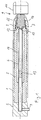
- FIG. 1 shows a first embodiment of the invention. It is a device for coupling shocks and unfocused (so-called radial) mechanical pressure waves in the human or animal body.
- the Zu Kunststoffkappe 2 contains a compressed air connection 4 for a pneumatic supply.
- a valve controlled by a control unit in particular a solenoid valve, is connected to this compressed air connection 4 via a pneumatic supply line, which injects compressed air pulses via the compressed air connection in a constant iterative cycle between approximately 1 Hz and 50 Hz.
- the valve is not shown and may also be installed in the illustrated device itself.
- the apparatus is designed as a device to be held by the hand of an operator, which is connected via the aforementioned pneumatic line to a base station, not shown, with the drive unit and the compressor and can be placed on the patient manually. It is used to treat soft tissue, especially muscles and fascia.
- a guide tube 6 is held in the housing via an insert 5, the end of which, in use, terminates in the inlet air cap 2 and communicates there with the compressed air connection 4.
- the body-side end of the guide tube 6 terminates in a part of the insert 5 which projects into the applicator cap 3, shortly before the end of the insert 5 and an interior 7 in the applicator cap 3.
- a first and in Fig. 1 hatched part of an applicator 9 was added. This is supported via an elastic hose member 10 made of an elastomer on a radial shoulder. A directed to the distant side and the impact surface-containing end 15 of the applicator 9 is supported on the insert 5 via an O-ring 12, specifically on an end face surrounding the already mentioned end of the insert 5. In this case, the O-ring 12 is located between this end face and a shoulder of the applicator 9.
- the applicator opening serves to guide the applicator 9, which is displaceable in the longitudinal direction, and fixes it transversely to the longitudinal direction.
- the Axialverschieb sadness is limited only by the flexibility of the elastomeric element 10 and can also lie well above 1 mm in a device operated in air relative to the remainder of the device.
- the applicator 9 has, as a second part, the non-hatched element 11, which forms the actual applicator to be applied to the skin.
- the applicator 9 is exchangeable by unscrewing the applicator cap 3.
- FIG. 1 In the adjacent region of the guide tube 6 is an in FIG. 1 projectile 13 in contact with the applicator 9 is inserted.
- the projectile 13 can by pressure differences of the air column in the guide tube 6 in front of and behind him (ie in FIG. 1 right and left of the projectile 13) are reciprocated in the guide tube and in particular to the applicator 9 to be accelerated.
- it is from a starting position (not shown) in FIG. 1 accelerated on the left by a compressed air surge through the compressed air port 4 and strikes with its applicator 9 facing the front surface on the applicator 9, on a body facing away baffle surface 15 thereof.
- the return movement of the projectile 13 is carried out in addition to a rebounding after the collision by a backflow of air from a guide tube 6 surrounding the insert 5 stowage chamber 14.
- the air is displaced in the acceleration of the projectile 13 in the direction of the baffle body 9 and so that compresses there.
- the solenoid valve shuts off the pressure while venting the space behind the projectile, the projectile 13 will thus become in the initial position moved back.
- this can also be done by an additional or alternative pressurization of the storage chamber 14 or another volume of air on the body side of the projectile 13.
- the distal end of the guide tube 6 in the application ends in a magnet holder for the projectile 13.
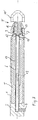
- the applicator 9 is hatched substantially to its radially slimmer in relation to the longitudinal axis of the device part 16 and in the remaining part 11 hatched. If one imagines the hatched part 16 completed with, for example, a slightly convex boundary line, it would form a conventional applicator shape. In this form, the applicator 9 would be particularly suitable for the vertical placement on the body surface of the patient. According to the invention, the applicator 9 is now enlarged in the direction of the patient's body, namely around the non-hatched part 11. This has seen in a direction perpendicular to the longitudinal direction in FIG. 1 given shape and in the second direction perpendicular to the first in FIG. 2b illustrated form. In this case, the applicator 9 in FIG.
- FIG. 1 approximately in the correct proportion to the rest of the device shown in FIG. 2 but enlarged. Its in terms of FIG. 1 Here, by way of example, vertical extent is 30 mm for a length (in the longitudinal direction) of 25 mm and patient-body-side radii of curvature in the transition between the two boundary surfaces in the projection according to FIG FIG. 1 of 5 mm.
- FIG. 2b on the other hand one recognizes with the same length (in the longitudinal direction) of 25 mm a narrow extension perpendicular to it, namely of 15 mm, and patient body side in the projection of the FIG. 2b a semicircular rounding with a radius of 7.5 mm.
- the FIG. 2 If one looks at the front part 11 of the applicator 9 in the longitudinal direction and recognizes a rectangular basic shape (with the already mentioned edge lengths of 30 mm or 50 mm), but with rounded corners with a radius of curvature of 5 mm.
- the fourth illustration d illustrates the applicator form in perspective view.
- the front surface of the front part 11 of the applicator 9 is thus in the perspective of the representation in FIG. 2b semi-cylindrical, but with rounded corners in two projection planes with radii of curvature of 5 mm, cf. the figures. Even without taking account of the additional fillets, this rounded half-cylinder shape accounts for one-third of the respective local areal proportions (or normals) to the longitudinal direction between 30 ° and 60 °; taking into account the further rounding, the proportion is still slightly higher.
- the corresponding angular sectors and surface areas are indicated by radii and hatching.
- the applicator 9 has a total and in particular with its front part 11 a twofold with respect to the longitudinal symmetry (and additionally two mirror symmetries, wherein the planes of symmetry intersect in the longitudinal direction) and is convex in its entire front surface. All occurring Curvature radii are at least 5 mm and the oblique front surface is approximately 2.5 cm 2 in total. Since in a typical application only one broad side of the applicator is applied, so for example in FIG. 2b the part of the front surface pointing to the left above is only a part of the skin contact. If you take the rounded side areas (in Figure 2c right and left), which do not rest on the skin, the contact area should be on the order of 1.0 to 1.2 cm 2 .
- the oblique front surface portion focuses in the direction of the longitudinal direction on the two long sides of the rounded rectangle.
- the applicator 9 may, for. B. aluminum, titanium, plastic, ceramic or wood.
- the components 11 and 16 With regard to its expandability, it makes sense to connect its components 11 and 16 firmly together, for example by a plug or screw connection.
- the components 11 and 16 may be made of different materials.
- the front portion 11 of the applicator could also be attached to an applicator similar to that shown in FIG. 4 the already quoted US 2011/0054367 A1 be provided and correspond here approximately with its widest extent the device diameter. Then it could be pulled forwards through the opening in the applicator cap after it has been loosened and other parts have been removed.
- FIG. 3 An alternative second embodiment show the Figures 3 and 4a to d , in the latter only the front applicator part 11 'is shown, the Fig. 3 in the same way on a device shows how Fig. 1 or you can imagine as in the cited US document on a device.
- Individual representations of Fig. 4 apart from the modified applicator form correspond to the individual representations of the Fig. 2 , wherein the width of the applicator 11 'according to Fig. 4b 20 mm (instead of 15 mm in Fig. 2b ) is.
- FIG. 4a relatively large oblique front surface portions at an angle of 45 ° to the longitudinal direction, these portions also extend into the rounded with a radius of 10 mm transitions between the inclined surfaces with each other and between the inclined surfaces and the parallel to the longitudinal direction of the device surfaces.
- Fig. 4b lacks the semi-cylindrical shape of the Fig. 2b ; instead, this is a rectangle with radii of curvature of 5 mm at the corners above.
- the oblique front surface portions thus consist essentially in the plane and at 45 ° to the longitudinal direction surfaces in FIG. 4 with a small part of the adjoining fillet, as indicated by hatching.
Description
Die vorliegende Erfindung bezieht sich auf ein Gerät zur Behandlung des menschlichen oder tierischen Körpers durch Ausüben von Stößen auf die Körperoberfläche. Im Folgenden wird zur Vereinfachung vom Körper eines Patienten gesprochen, der bevorzugt menschlich ist.The present invention relates to an apparatus for treating the human or animal body by exerting impacts on the body surface. For the sake of simplicity, the following is spoken of the body of a patient, who is preferably human.
Im Stand der Technik sind verschiedene Geräte des beschriebenen Grundtyps bekannt. Die
Der Schwerpunkt bei der Darstellung liegt in jedem Fall auf der durch die Kollision erzeugten Druckwelle, die mehr oder weniger einer eigentlichen Stoßwelle ähneln soll, wie sie klassische, in der Regel fokussierende Lithotripsiegeräte z. B. mit piezoelektrischen oder induktiven Aktuatoren und Fokussierung auf einen Stein erzeugen. Solche Druckwellen können Anstiegsflanken mit einer Breite im Bereich weniger µs und einer Amplitude im niedrigen zweistelligen MPa-Bereich haben (z. B. 2 µs und 15 MPa gemessen 1 cm vor der Frontfläche). In dem zitierten Dokument wird hingegen betont, dass die physikalisch an sich unvermeidliche makroskopische Schwerpunktbewegung des Applikators möglichst klein gehalten werden soll, weil sie als störend angesehen wird.The focus in the presentation is in any case on the pressure wave generated by the collision, which should more or less resemble an actual shock wave, as they are classic, usually focusing lithotripsy devices z. B. with piezoelectric or inductive actuators and focus on a stone. Such pressure waves may have leading edges with a width in the range of a few μs and an amplitude in the low two-digit MPa range (eg 2 μs and 15 MPa measured 1 cm in front of the front surface). In the cited document, however, it is emphasized that the physically inherently unavoidable macroscopic center of gravity movement of the applicator should be kept as small as possible, because it is regarded as disturbing.
Als zweites Beispiel wird auf die
Die vorliegende Erfindung richtet sich allgemein auf Geräte dieses Bautyps, und zwar sowohl hinsichtlich der Anwendung von Druckwellen als auch hinsichtlich der Anwendung "makroskopischer Stöße" des Applikator auf die Körperoberfläche.The present invention is generally directed to devices of this type of construction, both in terms of the application of pressure waves and the application of "macroscopic shocks" of the applicator to the body surface.
Zum Stand der Technik wird verwiesen auf die
Dabei liegt der Erfindung die Aufgabe zugrunde, ein solches Gerät hinsichtlich weitergehender Anwendungsmöglichkeiten auf der Patientenkörperoberfläche weiterzubilden.The invention has the object to further develop such a device with regard to further applications on the patient's body surface.
Die Aufgabe wird gelöst durch ein Gerät nach Anspruch 1. Erfindungsgemäß ist dabei zunächst vorgesehen, dass der Applikator einen schrägen Frontflächenanteil hat, der zumindest 30 % einer in Bezug auf die Stoßrichtung vorderen Frontfläche des Applikators beträgt, der in Bezug auf die Stoßrichtung schräg nach außen weist und der dabei einen Winkel zu der Stoßrichtung zwischen 30° und 60° bildet.The object is achieved by a device according to
Dementsprechend ist also eine Schrägfläche als wesentlicher Bestandteil der Frontfläche des Applikators vorgesehen. "Schräg" bedeutet dabei einen Winkel zu der Stoßrichtung zwischen 30° und 60°, wobei die Stoßrichtung in vielen praktisch wichtigen Fällen (z. B. bei Geräten in einer Bauform entsprechend zitierten Dokumenten) einer Längsrichtung des Geräts entspricht.Accordingly, therefore, an inclined surface is provided as an integral part of the front surface of the applicator. In this context, "oblique" means an angle to the impact direction between 30 ° and 60 °, the impact direction, in many practically important cases (eg, for devices in a design corresponding to cited documents), corresponding to a longitudinal direction of the device.
Die "Frontfläche" des Applikators soll die nach vorne weisenden Teile der Außenfläche beinhalten, die auf die Patientenkörperoberfläche aufgesetzt werden können, wobei "nach vorne weisend" bedeutet, dass eine lokale Flächennormale eine Komponente in Richtung der Stoßrichtung (und nicht etwa entgegengesetzt dazu oder nur senkrecht dazu) hat. Zur Stoßrichtung parallel liegende Flächen gehören also nicht zur Frontfläche und nach hinten weisende auch nicht.The "front surface" of the applicator is intended to include the forward facing portions of the outer surface that may be seated on the patient's surface, where "forward facing" means that a local surface normal has a component in the direction of impact (rather than opposite thereto or only perpendicular to it). Surfaces lying parallel to the impact direction thus do not belong to the front surface and also not to the rear.
Zusätzlich sind der schräge Frontflächenanteil und vorzugsweise die gesamte Frontfläche erfindungsgemäß kantenfrei. Das soll konkret bedeuten, dass die auftretenden Krümmungsradien mindestens 2 mm betragen, vorzugsweise mindestens 3 mm, 4 mm oder sogar mindestens 5 mm. Auch das kommt einem Einsatz des Geräts unter Krafteinwirkung durch den Therapeuten und/oder mit einer Schiebebewegung entgegen; der Therapeut muss dabei weniger auf die Haltung des Geräts und/oder auf mögliche Reizungen oder Verletzungen des Patienten durch Kanten achten, etwa Kanten am Rand einer eigentlich aufzusetzenden Applikatorfläche.In addition, the oblique front surface portion and preferably the entire front surface according to the invention are edge-free. In concrete terms this means that the occurring radii of curvature are at least 2 mm, preferably at least 3 mm, 4 mm or even at least 5 mm. This, too, is contrary to an application of the device under the influence of force by the therapist and / or with a sliding movement; the therapist must pay less attention to the posture of the device and / or to possible irritation or injury to the patient due to edges, such as edges on the edge of an applicator surface that is actually to be placed.
Schließlich soll die Schrägfläche insoweit einen wesentlichen Anteil der Frontfläche ausmachen, als sie zumindest 30 % ihres Flächenanteils beträgt, wobei ein Anteil von (in der folgenden Reihenfolge zunehmend bevorzugt) 35 %, 40 %, 45 %, 50 %, 55 %, 60 %, 65 %, 70 % zunehmend bevorzugt ist. Die Flächen werden dabei berücksichtigt, wie sie tatsächlich dreidimensional existieren, also nicht etwa als Projektionsflächen mit Blickrichtung von vorn.Finally, the slanted surface should account for a substantial proportion of the frontal area insofar as it is at least 30% of its areal proportion, with a proportion of (increasingly preferred in the following order) 35%, 40%, 45%, 50%, 55%, 60%. , 65%, 70% is increasingly preferred. The surfaces are taken into account as they actually exist three-dimensionally, ie not as projection surfaces with a view from the front.
Die Erfinder haben nämlich festgestellt, dass es praktisch sein kann, den Applikator in Bezug auf die Stoßrichtung schräg auf die Patientenkörperoberfläche aufzusetzen. Das betrifft insbesondere Behandlungen, bei denen das Gerät auf der Körperoberfläche bewegt wird. Dann greift sich das Gerät besser und kann in einer für den Therapeuten besser kontrollierbaren und bequemeren Weise über die Körperoberfläche geführt werden. Insbesondere können dabei Gewebepartien unter der Haut parallel massiert und/oder gewissermaßen vor dem Gerät hergeschoben werden, wobei sie gleichzeitig mit den Stößen und (in einem von Fall zu Fall unterschiedlichen Maß) Druckwellen beaufschlagt werden. Die konventionell bekannten Geräte mit mehr oder weniger flachen Frontflächen der Applikatoren sind dazu relativ schlecht geeignet, weil sie auf der Hautoberfläche nur bei mehr oder weniger senkrechter Stellung des Geräts relativ zur Körperoberfläche gehalten werden können.Namely, the inventors have found that it may be convenient to skew the applicator with respect to the impact direction onto the patient's body surface sit up. This particularly applies to treatments in which the device is moved on the body surface. Then the device gets better and can be guided over the body surface in a more controllable and comfortable way for the therapist. In particular, tissue sections under the skin can be massaged in parallel and / or pushed to a certain extent in front of the device, whereby they are acted on simultaneously with the shocks and (in a different case by case measure) pressure waves. The conventionally known devices with more or less flat front surfaces of the applicators are relatively poorly suited because they can be kept on the skin surface only at more or less vertical position of the device relative to the body surface.
Der Mechanismus zum Erzeugen der Stöße des Applikators ist in diesem Zusammenhang in unterschiedlichster Ausführung denkbar, insbesondere auch durch eine direkte Beaufschlagung des Applikators mittels eines elektromagnetischen Mechanismus oder auch eines Druckfluidpulses Bevorzugt ist aber die aus den zitierten Dokumenten bereits bekannte Verwendung eines beschleunigten Projektils zur Kollision mit dem Applikator, womit relativ heftige und (im Sinn der Applikatorgeschwindigkeit) schnelle Stöße realisiert werden können und auch die gleichzeitige oder sogar schwerpunktmäßige Verwendung von Druckwellen möglich ist. Das Projektil wiederum lässt sich ebenfalls in unterschiedlicher Weise beschleunigen, insbesondere auch elektromagnetisch, wobei auch hier eine pneumatische Beaufschlagung des Projektils gemäß den zitierten Schriften bevorzugt ist.The mechanism for generating the shocks of the applicator is conceivable in this connection in a wide variety of embodiments, in particular by direct application of the applicator by means of an electromagnetic mechanism or a pressure fluid pulse. However, the use of an accelerated projectile already known from the cited documents for collision with is preferred the applicator, whereby relatively violent and (in the sense of the applicator speed) rapid shocks can be realized and also the simultaneous or even main use of pressure waves is possible. The projectile, in turn, can also be accelerated in different ways, in particular also electromagnetically, in which case a pneumatic application of the projectile according to the cited documents is also preferred.
Der Begriff "Applikator" bezeichnet hier übrigens nicht zwingend ein einstückiges Teil. Es ist denkbar und anwendungsabhängig auch bevorzugt, dass das Projektil z. B. auf ein erstes Teil schlägt, das den Stoß und/oder die Druckwelle auf ein zweites Applikatorteil überträgt, das seinerseits mit der Haut des Patienten in Kontakt steht. Im Stand der Technik ist auch gelegentlich von einem Zwischenstück zwischen Applikator und Projektil die Rede; hier wird dann von einem mehrteiligen Applikator gesprochen, wobei die beiden Applikatorteile fest verbunden sein können, aber nicht sein müssen.Incidentally, the term "applicator" does not necessarily mean an integral part here. It is conceivable and application-dependent also preferred that the projectile z. B. strikes a first part that transmits the shock and / or the pressure wave to a second applicator, which in turn is in contact with the skin of the patient. The prior art also occasionally mentions an intermediate piece between the applicator and the projectile; Here is then a multipart Applicator spoken, wherein the two Applikatorteile can be firmly connected, but need not be.
Wie eingangs bereits erwähnt, kann ein relativ großer Hub des Applikators durchaus gewünscht sein, wobei im vorliegenden Zusammenhang das Gerät vorzugsweise so ausgelegt ist, dass Hübe über 1 mm erreichbar sind, wie schon in der
Die beschriebene schräge Fläche (in den Ansprüchen der schräge Frontflächenanteil) ist vorzugsweise nicht konkav, also flach oder konvex (was einen kombiniert flach-konvexen Fall beinhaltet), um einen guten Kontakt mit der Haut bzw. Körperoberfläche und eine konzentrierte Krafteinwirkung beim Auflegen zu ermöglichen.The described oblique surface (in the claims, the inclined front surface portion) is preferably not concave, ie flat or convex (which includes a combined flat-convex case), to allow a good contact with the skin or body surface and a concentrated application of force when placed ,
Ferner ist der schräge Frontflächenanteil insgesamt vorzugsweise mindestens 1,5 cm2 groß, wobei in der folgenden Reihenfolge folgende Untergrenzen zunehmend bevorzugt sind: 1,75 cm2 und schließlich 2,0 cm2. Mit zunehmender Flächengröße lässt sich ein größerer Gewebebereich erfassen und die Kraft des Stoßes und/oder die aufdrückende Kraft des Therapeuten breiter verteilen. Die oben genannten Werte beziehen sich dabei auf die gesamte schräge Frontfläche, wobei anwendungsabhängig nur ein Teil davon genutzt wird, zum Beispiel bei einer im Wesentlichen auf zwei Seiten verteilten Frontfläche nur die Hälfte auf der gerade zum Patienten hin orientierten Seite.Furthermore, the total inclined front surface portion is preferably at least 1.5 cm 2 in size, with the following lower limits being increasingly preferred in the following order: 1.75 cm 2 and finally 2.0 cm 2 . With increasing surface area, a larger area of tissue can be grasped and the force of the impact and / or the pushing force of the therapist can be distributed more widely. The abovementioned values refer to the entire oblique front surface, whereby depending on the application only a part of it is used, for example, in the case of a front surface distributed essentially on two sides, only half on the side which is just oriented towards the patient.
Ferner ist bevorzugt, dass ein großer Anteil des schrägen Frontflächenanteils relativ flach verläuft. Hier geht es nicht um die Kantenfreiheit, sondern um das Ausmaß in der Fläche verbleibender Krümmungen. Mindestens 80 % des Flächenanteils sollten einen Krümmungsradius von mindestens 5 mm aufweisen, vorzugsweise von mindestens 6 oder sogar 7 mm. Bei bestimmten Ausführungsformen mit praktisch flachen schrägen Frontflächenanteilen ist sogar eine Untergrenze von 10 mm, 20 mm, 30 mm, 40 mm oder sogar 50 mm bevorzugt.Furthermore, it is preferred that a large proportion of the oblique front surface portion is relatively flat. This is not about the edge freedom, but about the extent in the surface remaining curvatures. At least 80% of the area fraction should have a radius of curvature of at least 5 mm, preferably at least 6 or even 7 mm. In certain embodiments with practically flat oblique front surface portions, even a lower limit of 10 mm, 20 mm, 30 mm, 40 mm or even 50 mm is preferred.
Ein weiterer Aspekt der Erfindung betrifft die Symmetrie des Frontflächenanteils relativ zur Stoßrichtung (in der Regel auch Längsrichtung des Geräts). Im Stand der Technik sind, soweit bekannt, grundsätzlich rotationssymmetrische Applikatorgeometrien beschrieben. Im vorliegenden Fall aber sind gerade nicht vollständig rotationssymmetrische Geometrien bevorzugt. Grundsätzlich ist natürlich eine gewisse Symmetrie, also mit einer begrenzten Zähligkeit vorstellbar und, wie die Ausführungsbeispiele zeigen, durchaus auch günstig, wobei jedoch höchstens eine vierfache Zähligkeit, vorzugsweise nur eine dreifache oder sogar zweifache Zähligkeit bevorzugt sind. Anschaulich gesprochen bedeutet das, dass bei einer bestimmten Zähligkeit entsprechend viele einander symmetrisch entsprechende, also durch Drehung ineinander überführbare, schräge Frontflächenanteile vorhanden sind. Bei einer zweizähligen Symmetrie sind also zwei Schrägflächen gegeben, die beide in gleicher Weise eingesetzt werden können, und bei einer Dreizähligkeit derer drei. Eines der Ausführungsbeispiele zeigt eine nicht rotationssymmetrische, in diesem Fall allerdings spiegelsymmetrische Variante.Another aspect of the invention relates to the symmetry of the front surface portion relative to the direction of impact (usually also the longitudinal direction of the device). As far as is known, fundamentally rotationally symmetrical applicator geometries are described in the prior art. In the present case, however, not completely rotationally symmetric geometries are preferred. In principle, of course, a certain symmetry, that is, with a limited countability conceivable and, as the embodiments show, quite favorable, but at most a fourfold, preferably only a triple or even double counting are preferred. In a nutshell, that means that at a certain count corresponding many symmetrically corresponding, ie by rotation into one another, inclined front surface portions are present. In the case of a two-fold symmetry, therefore, there are two oblique surfaces, which can both be used in the same way, and at a trinity of the three of them. One of the embodiments shows a non-rotationally symmetrical, but in this case mirror-symmetrical variant.
In einem vergleichbaren Sinn ist ferner bevorzugt, dass sich der schräge Frontflächenanteil gewissermaßen auf einen Teil eines Rotationswinkels um die Stoßrichtung konzentriert. Anschaulich gesprochen bedeutet das, dass die schrägen Frontflächenanteile bei einem Blick auf den Applikator entgegengesetzt zur Stoßrichtung (also von vorn) nicht gleichmäßig um den Applikator herum verteilt sind, sondern auf 4, 3, 2 oder sogar nur eine Schrägfläche konzentriert.In a similar sense, it is further preferred that the oblique front surface portion, so to speak, concentrates on a part of a rotation angle about the impact direction. To put it clearly, this means that the oblique front surface portions are not evenly distributed around the applicator when looking at the applicator opposite to the direction of impact (ie from the front), but concentrated on 4, 3, 2 or even only one inclined surface.
Vorbekannte Applikatoren bestanden im Regelfall aus rostfreiem Stahl. Im vorliegenden Fall kommen grundsätzlich auch Metalle, so auch rostfreier Stahl, in Betracht. Daneben sind als metallische Materialien Aluminium und Titan zu nennen, wobei beide eine relativ geringe Massendichte haben und damit relativ leichte Applikatoren ermöglichen. Das kann den Vorteil haben, bei gegebener Geometrie eine stärkere Beschleunigung und damit auch größere Hubauslenkung des Applikators zu ermöglichen, was im vorliegenden Fall gewünscht sein kann. Titan zeichnet sich zudem durch eine besonders hohe mechanische Belastbarkeit aus, eignet sich also besonders für Anwendungen mit vergleichsweise hohen Projektilgeschwindigkeiten und/oder Projektilmassen. Da Titan außerdem eine besonders gute physiologische Verträglichkeit auszeichnet, kann es als Applikatormaterial auch unabhängig von der Belastbarkeit von Vorteil sein.Previously known applicators were usually made of stainless steel. In the present case, in principle, metals, including stainless steel, into consideration. In addition, aluminum and titanium are to be mentioned as metallic materials, both of which have a relatively low mass density and thus enable relatively light applicators. This can have the advantage of allowing for a given geometry, a greater acceleration and thus larger stroke deflection of the applicator, which may be desired in the present case. Titanium is also characterized by a particularly high mechanical strength, so it is particularly suitable for applications with comparatively high projectile speeds and / or projectile masses. Since titanium also has a particularly good physiological compatibility, it can also be advantageous as an applicator material regardless of the load-bearing capacity.
In Betracht kommen ferner Keramiken, vgl. Anmeldenummer 08 003 840.9 /
Im Folgenden wird die Erfindung auch anhand zweier Ausführungsbeispiele näher erläutert, deren einzelne Merkmale im Rahmen des geltenden Anspruchs 1 auch unabhängig voneinander und in anderen Kombinationen erfindungswesentlich sein können.
Figur 1- zeigt ein Druckwellengerät als erstes Ausführungsbeispiel der Erfindung mit einem in
Fig. 2 näher dargestellten Applikator. Figur 2- zeigt den Vorderteil des Applikators des Geräts aus
Fig. 1 in gleicher Blickrichtung wie inFig. 1 (aber aufrecht) in Teildarstellung a, in einer Schnittdarstellung mit um 90° um die Längsachse verdrehter Blickrichtung in Teildarstellung b, in einer weiteren Darstellung c in Längsrichtung des Geräts gesehen und schließlich in Teildarstellung d in perspektivischer Ansicht. - Figur 3
- zeigt ein zweites Ausführungsbeispiel analog
Fig. 1 , aber mit einem anderen, inFig. 4 dargestellten Applikator. - Figur 4
- zeigt den Vorderteil des Applikators des Geräts aus
Fig. 2 in gleicher Blickrichtung wie inFig. 1 (aber aufrecht) in Teildarstellung a, in einer Schnittdarstellung mit um 90° um die Längsachse verdrehter Blickrichtung in Teildarstellung b, in einer weiteren Darstellung c in Längsrichtung des Geräts gesehen und schließlich in Teildarstellung in d in perspektivischer Ansicht.
- FIG. 1
- shows a pressure wave device as a first embodiment of the invention with a in
Fig. 2 closer applicator. - FIG. 2
- shows the front part of the applicator of the device
Fig. 1 in the same direction as inFig. 1 (but upright) in partial view a, in a sectional view with rotated by 90 ° about the longitudinal axis viewing direction in partial view b, seen in a further representation c in the longitudinal direction of the device and finally in partial view d in a perspective view. - FIG. 3
- shows a second embodiment analog
Fig. 1 but with another, inFig. 4 illustrated applicator. - FIG. 4
- shows the front part of the applicator of the device
Fig. 2 in the same direction as inFig. 1 (but upright) in partial view a, in a sectional view with rotated by 90 ° about the longitudinal axis viewing direction in partial view b, seen in a further representation c in the longitudinal direction of the device and finally in partial view in d in perspective view.
Ein Rohrstück 1 bildet gemeinsam mit einer in der Anwendung körperabgewandten und mit dem Rohrstück 1 integrierten Zuluftkappe 2 und einer in der Anwendung körperzugewandten Applikatorkappe 3 ein Gehäuse. Die Zuluftkappe 2 enthält einen Druckluftanschluss 4 für eine pneumatische Versorgung. In an sich bekannter Weise ist an diesen Druckluftanschluss 4 über eine pneumatische Versorgungsleitung ein von einer Ansteuereinheit gesteuertes Ventil, insbesondere Magnetventil, angeschlossen, das in einem gleich bleibenden iterativen Takt zwischen etwa 1 Hz und 50 Hz Druckluftpulse über den Druckluftanschluss einkoppelt. Das Ventil ist nicht gezeigt und kann auch in dem dargestellten Gerät selbst eingebaut sein.A piece of
Das Gerät ist im Übrigen als mit der Hand einer Bedienungsperson zu haltendes Gerät ausgebildet, das über die erwähnte Pneumatikleitung an eine nicht gezeigte Basisstation mit der Ansteuereinheit und dem Kompressor angeschlossen ist und auf den Patienten manuell aufgesetzt werden kann. Es dient zur Behandlung von Weichgewebe, insbesondere Muskeln und Faszien.Incidentally, the apparatus is designed as a device to be held by the hand of an operator, which is connected via the aforementioned pneumatic line to a base station, not shown, with the drive unit and the compressor and can be placed on the patient manually. It is used to treat soft tissue, especially muscles and fascia.
In dem Gehäuse ist über einen Einsatz 5 ein Führungsrohr 6 gehalten, dessen bei der Anwendung körperfernes Ende in der Zuluftkappe 2 endet und dort mit dem Druckluftanschluss 4 kommuniziert. Das in der Anwendung körperseitige Ende des Führungsrohres 6 endet in einem Teil des Einsatzes 5, der in die Applikatorkappe 3 hineinragt, und zwar kurz vor dem dortigen Ende des Einsatzes 5 und einem Innenraum 7 in der Applikatorkappe 3.A
In dem Innenraum 7, der in eine in der Anwendung körperseitige Applikatoröffnung übergeht, ist ein erster und in
Der Applikator 9 weist als zweiten Teil das nicht schraffierte Element 11 auf, das den eigentlichen auf die Haut aufzusetzenden Applikator bildet. Der Applikator 9 ist durch Abschrauben der Applikatorkappe 3 austauschbar.The
In dem angrenzenden Bereich des Führungsrohres 6 ist ein in
Die Rückbewegung des Projektils 13 erfolgt zusätzlich zu einem Zurückprallen nach der Kollision durch ein Rückströmen der Luft aus einer das Führungsrohr 6 innerhalb des Einsatzes 5 umgebenden Staukammer 14. In diese wird die Luft bei der Beschleunigung des Projektils 13 in Richtung zu dem Prallkörper 9 verdrängt und damit dort komprimiert. Wenn das Magnetventil den Druck wegschaltet und gleichzeitig den Raum hinter dem Projektil entlüftet, wird das Projektil 13 damit in die Ausgangsstellung zurückbewegt. Dies kann natürlich auch durch eine zusätzliche oder alternative Druckbeaufschlagung der Staukammer 14 oder eines anderen Luftvolumens körperseitig von dem Projektil 13 erfolgen. Das in der Anwendung körperferne Ende des Führungsrohres 6 endet in einem Magnethalter für das Projektil 13.The return movement of the projectile 13 is carried out in addition to a rebounding after the collision by a backflow of air from a
In
In der dritten Darstellung c der
Die Frontfläche des vorderen Teils 11 des Applikators 9 ist also in der Perspektive der Darstellung in
Er ist im Hinblick auf die Längsrichtung von einer zweizähligen Symmetrie und kann mit den beiden jeweils 30 mm breiten, einem Viertel-Zylinder entsprechenden Frontflächenanteilen auf die Körperoberfläche des Patienten aufgelegt werden. Wenn dabei angenähert ein Aufliegewinkel von 45° verwendet wird, dann sind die Flächenanteile mit einem Winkel zwischen 30° und 60° zur Längsrichtung besonders bedeutsam. Der Relativanteil dieser Flächenanteile in Verbindung mit der im Vergleich zum Stand der Technik besonders breiten Ausführung (30 mm) und der starken Verrundung lassen die Applikatorfrontfläche besonders geeignet erscheinen, um auf der Körperoberfläche streichend oder schiebend bewegt zu werden. Aus den gleichen Gründen können Stöße mit relativ großen Hubwerten von über 1 mm vergleichsweise schonend und großflächig in den Körper eingekoppelt werden.It has a twofold symmetry with respect to the longitudinal direction and can be placed on the body surface of the patient with the two 30 mm wide, quarter-cylinder corresponding front surface portions. If approximately an angle of 45 ° is used, then the surface portions with an angle between 30 ° and 60 ° to the longitudinal direction are particularly significant. The relative proportion of these surface portions, in conjunction with the particularly wide version (30 mm) in comparison to the prior art, and the strong rounding make the applicator front surface appear particularly suitable for being moved on the body surface by stroking or pushing. For the same reasons, impacts with relatively large stroke values of more than 1 mm can be coupled into the body comparatively gently and over a large area.
Der Applikator 9 hat insgesamt und insbesondere mit seinem vorderen Teil 11 eine bezüglich der Längsrichtung zweizählige Symmetrie (und zusätzlich zwei Spiegelsymmetrien, wobei sich die Symmetrieebenen in der Längsrichtung schneiden) und ist dabei in seiner gesamten Frontfläche konvex. Alle auftretenden Krümmungsradien liegen bei mindestens 5 mm und die schräge Frontfläche liegt bei ungefähr über 2,5 cm2 insgesamt. Da bei einer typischen Anwendung nur eine Breitseite des Applikators angesetzt wird, also zum Beispiel in
Der schräge Frontflächenanteil konzentriert sich in Blickrichtung der Längsrichtung auf die beiden langen Seiten des abgerundeten Rechtecks.The oblique front surface portion focuses in the direction of the longitudinal direction on the two long sides of the rounded rectangle.
Der Applikator 9 kann z. B. aus Aluminium, Titan, Kunststoff, Keramik oder Holz bestehen.The
Hinsichtlich seiner Ausbaubarkeit bietet es sich an, seine Bestandteile 11 und 16 fest miteinander zu verbinden, zum Beispiel durch eine Steck- oder Schraubverbindung. Die Bestandteile 11 und 16 können aus unterschiedlichen Materialien hergestellt sein.With regard to its expandability, it makes sense to connect its
Alternativ könnte der vordere Teil 11 des Applikators auch an einem Applikator ähnlich der Darstellung in
Eine alternative zweite Ausführungsform zeigen die
Man erkennt in
Claims (10)
- An apparatus for treating a human or animal body, having- an applicator (9,11,11',16) for being placed on said body from the outside,- a housing (1-3) in which said applicator (9,11,11',16) is held, and- a mechanism (4,6,13) for generating strokes of said applicator (9,11,11',16) relative to said housing (1-3) in a stroke direction so that said strokes can be coupled into said body when said applicator is placed on said body,characterized in that said applicator (9,11,11',16)
has an oblique front area portion
which amounts to at least 30 % of a front area of said applicator (9,11,11',16), lying in front with respect to said stroke direction,
said front area portion pointing outwards obliquely with respect to said stroke direction,
and said front area portion having an angle to said stroke direction between 30° and 60°. - The apparatus according to claim 1, wherein said mechanism (4,6,13) for generating said strokes comprises a projectile (13) and a device (4,13) for accelerating said projectile in such a way that said projectile hits said applicator (9,11,11',16) and generates said stroke, thus, preferably a pneumatic device for accelerating said projectile (13).
- The apparatus according to one of the preceding claims, wherein said oblique front area portion is plane or convex but is not concave.
- The apparatus according to one of the preceding claims, wherein said front area as a whole is free of edges insofar as all radii of curvature shall be 2 mm at minimum.
- The apparatus according to one of the preceding claims, wherein said oblique front area portion has an overall area of 1.5 cm2 at minimum.
- The apparatus according to one of the preceding claims, wherein said oblique front area portion comprises a portion of 80 % at minimum, in which a radius of curvature is 5 mm at minimum.
- The apparatus according to one of the preceding claims, wherein said oblique front area portion has a rotational symmetry with respect to said stroke direction, which is fourfold at maximum, preferably threefold or even twofold at maximum.
- The apparatus according to claim 7, wherein said oblique front area portion is formed on four sides at a maximum, preferably on three sides at maximum or even two sides at maximum.
- The apparatus according to one of the preceding claims, wherein a part of said applicator, which is adapted for being placed on said body, is made of metal, in particular aluminium or titanium, synthetic material, ceramics or wood.
- The apparatus according to one of the preceding claims, which is adapted for a travel of said stroke of 1 mm at minimum in said stroke direction relatively to that housing.
Priority Applications (3)
| Application Number | Priority Date | Filing Date | Title |
|---|---|---|---|
| EP14186623.6A EP3000419B1 (en) | 2014-09-26 | 2014-09-26 | Device for treatment of the human or animal body with mechanical impacts |
| US14/865,742 US10667986B2 (en) | 2014-09-26 | 2015-09-25 | Apparatus for treating the human or animal body with mechanical strokes |
| CN201510859659.7A CN105534569B (en) | 2014-09-26 | 2015-09-28 | Utilize the equipment of mechanical shock disposition human or animal's body |
Applications Claiming Priority (1)
| Application Number | Priority Date | Filing Date | Title |
|---|---|---|---|
| EP14186623.6A EP3000419B1 (en) | 2014-09-26 | 2014-09-26 | Device for treatment of the human or animal body with mechanical impacts |
Publications (2)
| Publication Number | Publication Date |
|---|---|
| EP3000419A1 EP3000419A1 (en) | 2016-03-30 |
| EP3000419B1 true EP3000419B1 (en) | 2016-09-07 |
Family
ID=51619047
Family Applications (1)
| Application Number | Title | Priority Date | Filing Date |
|---|---|---|---|
| EP14186623.6A Active EP3000419B1 (en) | 2014-09-26 | 2014-09-26 | Device for treatment of the human or animal body with mechanical impacts |
Country Status (1)
| Country | Link |
|---|---|
| EP (1) | EP3000419B1 (en) |
Family Cites Families (9)
| Publication number | Priority date | Publication date | Assignee | Title |
|---|---|---|---|---|
| US4498464A (en) * | 1982-06-21 | 1985-02-12 | Morgan Jr Darrell W | Chiropractic instrument |
| US4549535A (en) * | 1982-12-06 | 1985-10-29 | Wing Thomas W | Linear motor massage apparatus |
| DE19725477C2 (en) * | 1997-06-17 | 1999-10-21 | Ferton Holding | Medical instrument for the treatment of biological tissue |
| US6503211B2 (en) * | 2001-05-25 | 2003-01-07 | Bruce A. Frye | Pneumatic spinal and extremity manipulator |
| DE20317386U1 (en) * | 2003-11-07 | 2005-01-13 | Storz Medical Ag | Device for treating body tissues with pressure/shock waves comprises a treatment head which at its distal end is provided with a removable cap covering the end of a plunger |
| US8500665B2 (en) | 2004-07-09 | 2013-08-06 | Storz Medical Ag | Instrument for applying vibrations to the human body |
| DE202004011323U1 (en) | 2004-07-09 | 2005-09-22 | Storz Medical Ag | Instrument for applying vibrations to the human body |
| EP2095843B1 (en) | 2008-02-29 | 2010-12-01 | Storz Medical Ag | Device for treating biological body substances with mechanical pressure waves |
| DE202014004070U1 (en) * | 2014-05-16 | 2014-07-28 | Martin Stock | Technical innovations of a vibration device for massage and stimulation therapy in human and animal use |
-
2014
- 2014-09-26 EP EP14186623.6A patent/EP3000419B1/en active Active
Also Published As
| Publication number | Publication date |
|---|---|
| EP3000419A1 (en) | 2016-03-30 |
Similar Documents
| Publication | Publication Date | Title |
|---|---|---|
| EP3388003B1 (en) | Pressure wave device | |
| EP2181730B1 (en) | Instrument for producing shock wave-like pressure waves for treating biological tissue | |
| EP2529679B1 (en) | Acoustic dampening casing for application to a pressure wave device | |
| DE19618972C2 (en) | Handheld device for use in lithotripsy | |
| EP2996585B1 (en) | Surgical instrument | |
| DE202015005257U1 (en) | Device for treating the human or animal body with mechanical shocks | |
| EP3000418B1 (en) | Device for treatment of the human or animal body with mechanical impacts | |
| DE102015103750A1 (en) | Syringe with a first and second syringe barrel | |
| DE202014007692U1 (en) | Device for treating the human or animal body with mechanical shocks | |
| DE10215416B4 (en) | Medical device for the treatment of biological tissue | |
| EP3000419B1 (en) | Device for treatment of the human or animal body with mechanical impacts | |
| DE102007013288B4 (en) | Apparatus for the treatment of biological body substances with mechanical pressure waves | |
| EP3124004B1 (en) | Device for treatment of the human or animal body with mechanical impacts | |
| DE202014010463U1 (en) | Device for treating the human or animal body with mechanical shocks | |
| DE202014010461U1 (en) | Device for treating the human or animal body with mechanical shocks | |
| DE10225709B4 (en) | Bellows for coupling a source of acoustic waves to a living being | |
| DE202017001951U1 (en) | Pressure wave machine | |
| DE202014008093U1 (en) | Massage toy with integrated moving balls | |
| EP3203968B1 (en) | Massage toy with integrated moveable balls | |
| DE19949385C2 (en) | Bone compacting device for dental implantology | |
| DE202014007693U1 (en) | Device for treating the human or animal body with mechanical shocks | |
| DE202007007922U1 (en) | Medical device for treating the human or animal body with mechanical pressure or shock waves | |
| DE102021104566A1 (en) | Device for treating the human or animal body with mechanical impact | |
| DE202021100954U1 (en) | Device for treating the human or animal body with mechanical shocks | |
| DE202016103231U1 (en) | Aids for knotting balloons |
Legal Events
| Date | Code | Title | Description |
|---|---|---|---|
| PUAI | Public reference made under article 153(3) epc to a published international application that has entered the european phase |
Free format text: ORIGINAL CODE: 0009012 |
|
| 17P | Request for examination filed |
Effective date: 20150609 |
|
| AK | Designated contracting states |
Kind code of ref document: A1 Designated state(s): AL AT BE BG CH CY CZ DE DK EE ES FI FR GB GR HR HU IE IS IT LI LT LU LV MC MK MT NL NO PL PT RO RS SE SI SK SM TR |
|
| AX | Request for extension of the european patent |
Extension state: BA ME |
|
| GRAP | Despatch of communication of intention to grant a patent |
Free format text: ORIGINAL CODE: EPIDOSNIGR1 |
|
| INTG | Intention to grant announced |
Effective date: 20160530 |
|
| GRAS | Grant fee paid |
Free format text: ORIGINAL CODE: EPIDOSNIGR3 |
|
| GRAA | (expected) grant |
Free format text: ORIGINAL CODE: 0009210 |
|
| RBV | Designated contracting states (corrected) |
Designated state(s): AL AT BE BG CH CY CZ DE DK EE ES FI FR GB GR HR HU IE IS IT LI LT LU LV MC MK MT NL NO PL PT RO RS SE SI SK SM TR |
|
| AK | Designated contracting states |
Kind code of ref document: B1 Designated state(s): AL AT BE BG CH CY CZ DE DK EE ES FI FR GB GR HR HU IE IS IT LI LT LU LV MC MK MT NL NO PL PT RO RS SE SI SK SM TR |
|
| REG | Reference to a national code |
Ref country code: GB Ref legal event code: FG4D Free format text: NOT ENGLISH |
|
| REG | Reference to a national code |
Ref country code: CH Ref legal event code: EP |
|
| REG | Reference to a national code |
Ref country code: IE Ref legal event code: FG4D Free format text: LANGUAGE OF EP DOCUMENT: GERMAN |
|
| REG | Reference to a national code |
Ref country code: CH Ref legal event code: NV Representative=s name: E. BLUM AND CO. AG PATENT- UND MARKENANWAELTE , CH |
|
| REG | Reference to a national code |
Ref country code: AT Ref legal event code: REF Ref document number: 826110 Country of ref document: AT Kind code of ref document: T Effective date: 20161015 |
|
| REG | Reference to a national code |
Ref country code: DE Ref legal event code: R096 Ref document number: 502014001399 Country of ref document: DE |
|
| REG | Reference to a national code |
Ref country code: FR Ref legal event code: PLFP Year of fee payment: 3 |
|
| REG | Reference to a national code |
Ref country code: LT Ref legal event code: MG4D |
|
| REG | Reference to a national code |
Ref country code: NL Ref legal event code: MP Effective date: 20160907 |
|
| PG25 | Lapsed in a contracting state [announced via postgrant information from national office to epo] |
Ref country code: HR Free format text: LAPSE BECAUSE OF FAILURE TO SUBMIT A TRANSLATION OF THE DESCRIPTION OR TO PAY THE FEE WITHIN THE PRESCRIBED TIME-LIMIT Effective date: 20160907 Ref country code: RS Free format text: LAPSE BECAUSE OF FAILURE TO SUBMIT A TRANSLATION OF THE DESCRIPTION OR TO PAY THE FEE WITHIN THE PRESCRIBED TIME-LIMIT Effective date: 20160907 Ref country code: LT Free format text: LAPSE BECAUSE OF FAILURE TO SUBMIT A TRANSLATION OF THE DESCRIPTION OR TO PAY THE FEE WITHIN THE PRESCRIBED TIME-LIMIT Effective date: 20160907 Ref country code: NO Free format text: LAPSE BECAUSE OF FAILURE TO SUBMIT A TRANSLATION OF THE DESCRIPTION OR TO PAY THE FEE WITHIN THE PRESCRIBED TIME-LIMIT Effective date: 20161207 Ref country code: FI Free format text: LAPSE BECAUSE OF FAILURE TO SUBMIT A TRANSLATION OF THE DESCRIPTION OR TO PAY THE FEE WITHIN THE PRESCRIBED TIME-LIMIT Effective date: 20160907 |
|
| PG25 | Lapsed in a contracting state [announced via postgrant information from national office to epo] |
Ref country code: BE Free format text: LAPSE BECAUSE OF NON-PAYMENT OF DUE FEES Effective date: 20160930 Ref country code: SE Free format text: LAPSE BECAUSE OF FAILURE TO SUBMIT A TRANSLATION OF THE DESCRIPTION OR TO PAY THE FEE WITHIN THE PRESCRIBED TIME-LIMIT Effective date: 20160907 Ref country code: NL Free format text: LAPSE BECAUSE OF FAILURE TO SUBMIT A TRANSLATION OF THE DESCRIPTION OR TO PAY THE FEE WITHIN THE PRESCRIBED TIME-LIMIT Effective date: 20160907 Ref country code: GR Free format text: LAPSE BECAUSE OF FAILURE TO SUBMIT A TRANSLATION OF THE DESCRIPTION OR TO PAY THE FEE WITHIN THE PRESCRIBED TIME-LIMIT Effective date: 20161208 Ref country code: LV Free format text: LAPSE BECAUSE OF FAILURE TO SUBMIT A TRANSLATION OF THE DESCRIPTION OR TO PAY THE FEE WITHIN THE PRESCRIBED TIME-LIMIT Effective date: 20160907 Ref country code: ES Free format text: LAPSE BECAUSE OF FAILURE TO SUBMIT A TRANSLATION OF THE DESCRIPTION OR TO PAY THE FEE WITHIN THE PRESCRIBED TIME-LIMIT Effective date: 20160907 |
|
| PG25 | Lapsed in a contracting state [announced via postgrant information from national office to epo] |
Ref country code: EE Free format text: LAPSE BECAUSE OF FAILURE TO SUBMIT A TRANSLATION OF THE DESCRIPTION OR TO PAY THE FEE WITHIN THE PRESCRIBED TIME-LIMIT Effective date: 20160907 Ref country code: RO Free format text: LAPSE BECAUSE OF FAILURE TO SUBMIT A TRANSLATION OF THE DESCRIPTION OR TO PAY THE FEE WITHIN THE PRESCRIBED TIME-LIMIT Effective date: 20160907 |
|
| PG25 | Lapsed in a contracting state [announced via postgrant information from national office to epo] |
Ref country code: BG Free format text: LAPSE BECAUSE OF FAILURE TO SUBMIT A TRANSLATION OF THE DESCRIPTION OR TO PAY THE FEE WITHIN THE PRESCRIBED TIME-LIMIT Effective date: 20161207 Ref country code: SM Free format text: LAPSE BECAUSE OF FAILURE TO SUBMIT A TRANSLATION OF THE DESCRIPTION OR TO PAY THE FEE WITHIN THE PRESCRIBED TIME-LIMIT Effective date: 20160907 Ref country code: PT Free format text: LAPSE BECAUSE OF FAILURE TO SUBMIT A TRANSLATION OF THE DESCRIPTION OR TO PAY THE FEE WITHIN THE PRESCRIBED TIME-LIMIT Effective date: 20170109 Ref country code: SK Free format text: LAPSE BECAUSE OF FAILURE TO SUBMIT A TRANSLATION OF THE DESCRIPTION OR TO PAY THE FEE WITHIN THE PRESCRIBED TIME-LIMIT Effective date: 20160907 Ref country code: IS Free format text: LAPSE BECAUSE OF FAILURE TO SUBMIT A TRANSLATION OF THE DESCRIPTION OR TO PAY THE FEE WITHIN THE PRESCRIBED TIME-LIMIT Effective date: 20170107 Ref country code: PL Free format text: LAPSE BECAUSE OF FAILURE TO SUBMIT A TRANSLATION OF THE DESCRIPTION OR TO PAY THE FEE WITHIN THE PRESCRIBED TIME-LIMIT Effective date: 20160907 Ref country code: CZ Free format text: LAPSE BECAUSE OF FAILURE TO SUBMIT A TRANSLATION OF THE DESCRIPTION OR TO PAY THE FEE WITHIN THE PRESCRIBED TIME-LIMIT Effective date: 20160907 |
|
| REG | Reference to a national code |
Ref country code: DE Ref legal event code: R097 Ref document number: 502014001399 Country of ref document: DE |
|
| REG | Reference to a national code |
Ref country code: IE Ref legal event code: MM4A |
|
| PLBE | No opposition filed within time limit |
Free format text: ORIGINAL CODE: 0009261 |
|
| STAA | Information on the status of an ep patent application or granted ep patent |
Free format text: STATUS: NO OPPOSITION FILED WITHIN TIME LIMIT |
|
| PG25 | Lapsed in a contracting state [announced via postgrant information from national office to epo] |
Ref country code: DK Free format text: LAPSE BECAUSE OF FAILURE TO SUBMIT A TRANSLATION OF THE DESCRIPTION OR TO PAY THE FEE WITHIN THE PRESCRIBED TIME-LIMIT Effective date: 20160907 Ref country code: IE Free format text: LAPSE BECAUSE OF NON-PAYMENT OF DUE FEES Effective date: 20160926 |
|
| 26N | No opposition filed |
Effective date: 20170608 |
|
| PG25 | Lapsed in a contracting state [announced via postgrant information from national office to epo] |
Ref country code: SI Free format text: LAPSE BECAUSE OF FAILURE TO SUBMIT A TRANSLATION OF THE DESCRIPTION OR TO PAY THE FEE WITHIN THE PRESCRIBED TIME-LIMIT Effective date: 20160907 Ref country code: LU Free format text: LAPSE BECAUSE OF NON-PAYMENT OF DUE FEES Effective date: 20160926 |
|
| REG | Reference to a national code |
Ref country code: FR Ref legal event code: PLFP Year of fee payment: 4 |
|
| REG | Reference to a national code |
Ref country code: BE Ref legal event code: MM Effective date: 20160930 |
|
| PG25 | Lapsed in a contracting state [announced via postgrant information from national office to epo] |
Ref country code: HU Free format text: LAPSE BECAUSE OF FAILURE TO SUBMIT A TRANSLATION OF THE DESCRIPTION OR TO PAY THE FEE WITHIN THE PRESCRIBED TIME-LIMIT; INVALID AB INITIO Effective date: 20140926 |
|
| PG25 | Lapsed in a contracting state [announced via postgrant information from national office to epo] |
Ref country code: MK Free format text: LAPSE BECAUSE OF FAILURE TO SUBMIT A TRANSLATION OF THE DESCRIPTION OR TO PAY THE FEE WITHIN THE PRESCRIBED TIME-LIMIT Effective date: 20160907 Ref country code: MT Free format text: LAPSE BECAUSE OF FAILURE TO SUBMIT A TRANSLATION OF THE DESCRIPTION OR TO PAY THE FEE WITHIN THE PRESCRIBED TIME-LIMIT Effective date: 20160907 Ref country code: CY Free format text: LAPSE BECAUSE OF FAILURE TO SUBMIT A TRANSLATION OF THE DESCRIPTION OR TO PAY THE FEE WITHIN THE PRESCRIBED TIME-LIMIT Effective date: 20160907 Ref country code: MC Free format text: LAPSE BECAUSE OF FAILURE TO SUBMIT A TRANSLATION OF THE DESCRIPTION OR TO PAY THE FEE WITHIN THE PRESCRIBED TIME-LIMIT Effective date: 20160907 |
|
| REG | Reference to a national code |
Ref country code: FR Ref legal event code: PLFP Year of fee payment: 5 |
|
| PG25 | Lapsed in a contracting state [announced via postgrant information from national office to epo] |
Ref country code: TR Free format text: LAPSE BECAUSE OF FAILURE TO SUBMIT A TRANSLATION OF THE DESCRIPTION OR TO PAY THE FEE WITHIN THE PRESCRIBED TIME-LIMIT Effective date: 20160907 Ref country code: AL Free format text: LAPSE BECAUSE OF FAILURE TO SUBMIT A TRANSLATION OF THE DESCRIPTION OR TO PAY THE FEE WITHIN THE PRESCRIBED TIME-LIMIT Effective date: 20160907 |
|
| REG | Reference to a national code |
Ref country code: AT Ref legal event code: MM01 Ref document number: 826110 Country of ref document: AT Kind code of ref document: T Effective date: 20190926 |
|
| PG25 | Lapsed in a contracting state [announced via postgrant information from national office to epo] |
Ref country code: AT Free format text: LAPSE BECAUSE OF NON-PAYMENT OF DUE FEES Effective date: 20190926 |
|
| P01 | Opt-out of the competence of the unified patent court (upc) registered |
Effective date: 20230504 |
|
| PGFP | Annual fee paid to national office [announced via postgrant information from national office to epo] |
Ref country code: GB Payment date: 20230920 Year of fee payment: 10 |
|
| PGFP | Annual fee paid to national office [announced via postgrant information from national office to epo] |
Ref country code: FR Payment date: 20230922 Year of fee payment: 10 Ref country code: DE Payment date: 20230919 Year of fee payment: 10 |
|
| PGFP | Annual fee paid to national office [announced via postgrant information from national office to epo] |
Ref country code: IT Payment date: 20230922 Year of fee payment: 10 Ref country code: CH Payment date: 20231001 Year of fee payment: 10 |