EP3000388B1 - Sensor und system zur messung biologischer signale - Google Patents
Sensor und system zur messung biologischer signale Download PDFInfo
- Publication number
- EP3000388B1 EP3000388B1 EP15185419.7A EP15185419A EP3000388B1 EP 3000388 B1 EP3000388 B1 EP 3000388B1 EP 15185419 A EP15185419 A EP 15185419A EP 3000388 B1 EP3000388 B1 EP 3000388B1
- Authority
- EP
- European Patent Office
- Prior art keywords
- light
- sensor
- subject
- pressure
- blood
- Prior art date
- Legal status (The legal status is an assumption and is not a legal conclusion. Google has not performed a legal analysis and makes no representation as to the accuracy of the status listed.)
- Active
Links
Images






Classifications
-
- A—HUMAN NECESSITIES
- A61—MEDICAL OR VETERINARY SCIENCE; HYGIENE
- A61B—DIAGNOSIS; SURGERY; IDENTIFICATION
- A61B5/00—Measuring for diagnostic purposes; Identification of persons
- A61B5/02—Detecting, measuring or recording for evaluating the cardiovascular system, e.g. pulse, heart rate, blood pressure or blood flow
- A61B5/02028—Determining haemodynamic parameters not otherwise provided for, e.g. cardiac contractility or left ventricular ejection fraction
-
- A—HUMAN NECESSITIES
- A61—MEDICAL OR VETERINARY SCIENCE; HYGIENE
- A61B—DIAGNOSIS; SURGERY; IDENTIFICATION
- A61B5/00—Measuring for diagnostic purposes; Identification of persons
- A61B5/0059—Measuring for diagnostic purposes; Identification of persons using light, e.g. diagnosis by transillumination, diascopy, fluorescence
-
- A—HUMAN NECESSITIES
- A61—MEDICAL OR VETERINARY SCIENCE; HYGIENE
- A61B—DIAGNOSIS; SURGERY; IDENTIFICATION
- A61B5/00—Measuring for diagnostic purposes; Identification of persons
- A61B5/02—Detecting, measuring or recording for evaluating the cardiovascular system, e.g. pulse, heart rate, blood pressure or blood flow
- A61B5/021—Measuring pressure in heart or blood vessels
- A61B5/022—Measuring pressure in heart or blood vessels by applying pressure to close blood vessels, e.g. against the skin; Ophthalmodynamometers
- A61B5/02233—Occluders specially adapted therefor
-
- A—HUMAN NECESSITIES
- A61—MEDICAL OR VETERINARY SCIENCE; HYGIENE
- A61B—DIAGNOSIS; SURGERY; IDENTIFICATION
- A61B5/00—Measuring for diagnostic purposes; Identification of persons
- A61B5/02—Detecting, measuring or recording for evaluating the cardiovascular system, e.g. pulse, heart rate, blood pressure or blood flow
- A61B5/026—Measuring blood flow
- A61B5/0261—Measuring blood flow using optical means, e.g. infrared light
-
- A—HUMAN NECESSITIES
- A61—MEDICAL OR VETERINARY SCIENCE; HYGIENE
- A61B—DIAGNOSIS; SURGERY; IDENTIFICATION
- A61B5/00—Measuring for diagnostic purposes; Identification of persons
- A61B5/68—Arrangements of detecting, measuring or recording means, e.g. sensors, in relation to patient
- A61B5/6801—Arrangements of detecting, measuring or recording means, e.g. sensors, in relation to patient specially adapted to be attached to or worn on the body surface
- A61B5/683—Means for maintaining contact with the body
- A61B5/6831—Straps, bands or harnesses
-
- A—HUMAN NECESSITIES
- A61—MEDICAL OR VETERINARY SCIENCE; HYGIENE
- A61B—DIAGNOSIS; SURGERY; IDENTIFICATION
- A61B2560/00—Constructional details of operational features of apparatus; Accessories for medical measuring apparatus
- A61B2560/04—Constructional details of apparatus
- A61B2560/0462—Apparatus with built-in sensors
-
- A—HUMAN NECESSITIES
- A61—MEDICAL OR VETERINARY SCIENCE; HYGIENE
- A61B—DIAGNOSIS; SURGERY; IDENTIFICATION
- A61B5/00—Measuring for diagnostic purposes; Identification of persons
- A61B5/0048—Detecting, measuring or recording by applying mechanical forces or stimuli
- A61B5/0053—Detecting, measuring or recording by applying mechanical forces or stimuli by applying pressure, e.g. compression, indentation, palpation, grasping, gauging
-
- A—HUMAN NECESSITIES
- A61—MEDICAL OR VETERINARY SCIENCE; HYGIENE
- A61B—DIAGNOSIS; SURGERY; IDENTIFICATION
- A61B5/00—Measuring for diagnostic purposes; Identification of persons
- A61B5/02—Detecting, measuring or recording for evaluating the cardiovascular system, e.g. pulse, heart rate, blood pressure or blood flow
- A61B5/024—Measuring pulse rate or heart rate
- A61B5/02416—Measuring pulse rate or heart rate using photoplethysmograph signals, e.g. generated by infrared radiation
- A61B5/02422—Measuring pulse rate or heart rate using photoplethysmograph signals, e.g. generated by infrared radiation within occluders
-
- A—HUMAN NECESSITIES
- A61—MEDICAL OR VETERINARY SCIENCE; HYGIENE
- A61B—DIAGNOSIS; SURGERY; IDENTIFICATION
- A61B5/00—Measuring for diagnostic purposes; Identification of persons
- A61B5/68—Arrangements of detecting, measuring or recording means, e.g. sensors, in relation to patient
- A61B5/6801—Arrangements of detecting, measuring or recording means, e.g. sensors, in relation to patient specially adapted to be attached to or worn on the body surface
- A61B5/6813—Specially adapted to be attached to a specific body part
- A61B5/6814—Head
-
- A—HUMAN NECESSITIES
- A61—MEDICAL OR VETERINARY SCIENCE; HYGIENE
- A61B—DIAGNOSIS; SURGERY; IDENTIFICATION
- A61B5/00—Measuring for diagnostic purposes; Identification of persons
- A61B5/68—Arrangements of detecting, measuring or recording means, e.g. sensors, in relation to patient
- A61B5/6801—Arrangements of detecting, measuring or recording means, e.g. sensors, in relation to patient specially adapted to be attached to or worn on the body surface
- A61B5/6813—Specially adapted to be attached to a specific body part
- A61B5/6824—Arm or wrist
-
- A—HUMAN NECESSITIES
- A61—MEDICAL OR VETERINARY SCIENCE; HYGIENE
- A61B—DIAGNOSIS; SURGERY; IDENTIFICATION
- A61B5/00—Measuring for diagnostic purposes; Identification of persons
- A61B5/68—Arrangements of detecting, measuring or recording means, e.g. sensors, in relation to patient
- A61B5/6801—Arrangements of detecting, measuring or recording means, e.g. sensors, in relation to patient specially adapted to be attached to or worn on the body surface
- A61B5/6813—Specially adapted to be attached to a specific body part
- A61B5/6828—Leg
Definitions
- the presently disclosed subject matter relates to a sensor and a biological signal measuring system.
- a blood refill time is one of indexes for observing a tissue perfusion of a subject.
- the blood refill time is used as a simple index for evaluating whether shock has occurred.
- the blood refill time is widely used in the field of emergency medicine for the purpose of determining necessity of transfusion, triage (evaluation of priority in a case where many persons are injured or sickened) or the like.
- a medical person when measuring a blood refill time, a medical person applies pressure on a living tissue of a subject, such as a finger nail, and after the pressure is released, visually checks the color change of the nail or the skin. When the color returns to an original color within approximately two seconds, it is determined that the subject is in a normal condition. In this technique, however, because the living tissue is manually pressed and the change of the skin color is visually checked, it cannot provide quantitative results and an error easily occurs.
- a related art blood refill time measurement uses a pulse oximeter (see, e.g., US2007/0282182A1 ). More specifically, light of a wavelength which can be absorbed by blood enters living tissue, and the intensity of light which transmits through the living tissue is measured by an optical sensor. In this case, when the living tissue is pressed by using an actuator, blood is evacuated from the living tissue of the pressed portion, and hence the intensity of the transmitted light is increased. When the pressure is released, the living tissue of the portion is filled with blood, and therefore the intensity of the transmitted light is decreased. The blood refill time is identified based on the time elapsed from the release of the pressure until the transmitted light intensity returns to the original level.
- US 2014/0275891 A1 describes an optical tomography sensor to be placed on the head.
- EP 2762075 A1 describes a optical signal measuring system identifying a blood fill time.
- the living tissue may compressed by using an air bag or the like. Depending on the material of the air bag, however, the light entering the living tissue, and the transmitted light (or reflected light) from the living tissue are affected, and the accuracy of measurement results may be lowered.
- Illustrative aspects of the present invention provide a sensor and a biological signal measuring system configured to perform an accurate measurement of blood refill time.
- a sensor is configured to measure a blood refill time of a living tissue of a subject.
- the sensor is defined according to claim 1.
- a biological signal measuring system includes the sensor described above, and a biological signal measuring apparatus configured to calculate the blood refill time of the subject based on an amount of light received by the sensor.
- FIG. 1 is a block diagram illustrating a configuration of a biological signal measuring system.
- the biological signal measuring system 1 includes a sensor 10 and a biological signal measuring apparatus 20.
- the sensor 10 is used for measuring a blood refill time of a subject.
- the sensor 10 is configured to apply pressure on a living tissue (for example, an arm or a forehead) of the subject, emit light toward the living tissue, and receive reflected light or transmitted light from the living tissue.
- the sensor 10 sends a detection signal indicating the amount of light received from the living tissue to the biological signal measuring apparatus 20.
- the configuration of the sensor 10 will be described later with reference to Fig. 3 .
- the biological signal measuring apparatus 20 includes a controller 21, an input section 22, and an output section 23.
- the controller 21 includes a pressure adjusting section 211 and a blood refill time measuring section 212.
- the pressure adjusting section 211 adjusts the strength of pressure applied by the sensor 10 to the living tissue of the subject. Specifically, the pressure adjusting section 211 sends a control signal (hereinafter, a pressure control signal) to the sensor 10 to control the strength of pressure applied to the subject by the sensor 10. Generally, it is considered that the normal blood refill time is two seconds or less. Therefore, the pressure adjusting section 211 reduces the pressure so that the time period from the start of reduction of the pressure to the end of the application of pressure is shorter than two seconds (i.e., the time constant of the pressure reduction is equal to or less than two seconds).
- a control signal hereinafter, a pressure control signal
- the controller 21 controls the amount of light to be emitted from the sensor 10 and the timing of the light emission by using a control signal.
- the blood refill time measuring section 212 acquires the amount of light received by the sensor 10 in each of time periods (for example, before the start of the application of pressure, during the application of pressure, and after the end of the application of pressure). Then, the blood refill time measuring section 212 measures the blood refill time in accordance with a change in the amount of received light. The process of measuring the blood refill time will be described in detail with reference to the flowchart of Fig. 2 .
- the controller 21 starts emission and reception of light at a predetermined timing (for example, every 30 minutes) (S11).
- the pressure adjusting section 211 performs a control so as not to apply pressure on the living tissue.
- the blood refill time measuring section 212 measures the amount of received light before an application of pressure on the living tissue, from the sensor 10 (S12). After acquisition of the amount of received light before the application of pressure, the pressure adjusting section 211 starts to apply pressure on the living tissue (S13).
- the blood refill time measuring section 212 measures the amount of received light in the state of pressure being applied on the living tissue, from the sensor 10 (S14). After the application of pressure is sufficiently performed, the pressure adjusting section 211 releases the pressure on the living tissue (S15).
- the blood refill time measuring section 212 computes or calculates the time elapsed from the timing when the pressure on the living tissue is released, until when the amount of received light attenuates to a value that is approximately equal to that before the application of pressure, as the blood refill time (S16).
- An example of a method of calculating the blood refill time is disclosed in JP2012-115640A .
- the blood refill time may be calculated by using a change of the amount of received light after the application of pressure, without using the amount of received light before the application of pressure. That is, the blood refill time measuring section 212 may use any kind of algorithm in so far as the blood refill time can be identified by using a change of the amount of received light after the application of pressure on the living tissue.
- the input section 22 is configured by input interfaces such as buttons and knobs disposed on the biological signal measuring apparatus 20, a control circuit for the interfaces, and the like.
- the output section 23 outputs the blood refill time which is measured by the controller 21.
- the output section 23 displays the blood refill time on a liquid crystal display disposed on the housing of the biological signal measuring apparatus 20.
- the outputting process by the output section 23 includes not only the display on the screen, but also a print output, writing into an electronic file, and the like.
- the input section 22 and the output section 23 may be configured such that the display of information and the operation input can be simultaneously performed as in a touch panel.
- Fig. 3 is a sectional view of the sensor 10.
- the sensor 10 is attached to a head, an arm or the like of the subject.
- the sensor 10 emits light of a predetermined wavelength toward the living tissue, and receives reflected light or transmitted light from the living tissue. Specific examples of the sensor 10 will be later described.
- the sensor 10 includes a light emitter 11, a first light transmitting member 12, a light receiver 13, a second light transmitting member 14, and a light blocking member 15.
- a contact surface 16 contacts a surface of a living tissue of a subject.
- the light emitter 11 emits light of a predetermined wavelength toward the living tissue of the subject (downward in Fig. 3 ).
- the light emitted from the light emitter 11 passes through the first light transmitting member 12 and enters the living tissue of the subject.
- the light emitter 11 has a light emitting device that emits light.
- the light emitting device is, for example, a laser diode, a light emitting diode (LED) or the like.
- the light emitter 11 may include a plurality of light emitting devices, and the light emitting devices may respectively emit light of different wavelengths (for example, 660 nm and 940 nm) at timings in accordance with the control by the controller 21.
- the first light transmitting member 12 is configured to guide the light emitted from the light emitter 11 toward the living tissue of the subject. That is, the first light transmitting member 12 is arranged such that one side (one end) of the first light transmitting member 12 provides a contact surface contacting the light emitter 11, and the other side (other end) of the first light transmitting member 12 provides a contact surface to contact the subject.
- the first light transmitting member 12 is made of a material having a high light transmission rate (light transmitting material), such as silicon rubber, elastomer, polyvinyl chloride, polycarbonate, ABS, polyurethane, plant fibers, or nylon.
- the light transmission rate of the first light transmitting member 12 is preferably about 30% to 100%.
- the second light transmitting member 14 is configured to guide reflected light or transmitted light from the living tissue of the subject toward the light receiver 13. That is, the second light transmitting member 14 is arranged such that one side (one end) of the second light transmitting member 14 provides a contact surface contacting the light receiver 13, and the other side (other end) the second light transmitting member 14 provides a contact surface to contact the subject.
- the second light transmitting member 14 is made of a material having a high light transmission rate (light transmitting material), such as silicon rubber, elastomer, polyvinyl chloride, polycarbonate, ABS, polyurethane, plant fibers, or nylon.
- the light transmission rate of the second light transmitting member 14 is preferably about 30% to 100%.
- the light receiver 13 receives reflected light or transmitted light from the living tissue of the subject.
- the light receiver 13 sends a light reception signal corresponding to the amount of received light (intensity of the received light), to the biological signal measuring apparatus 20.
- the light receiver 13 produces the light reception signal by a light receiving device provided therein.
- An example of the light receiving device is a photodiode.
- the light blocking member 15 is disposed between the light emitter 11 and the light receiver 13, and has a low light transmission rate. In other words, the light blocking member 15 has a lower light transmission rate (second light transmission rate) than the light transmission rate (first light transmission rate) of the first light transmitting member 12 and the second light transmitting member 14.
- the light blocking member 15 is configured to block light so that the light emitted from the light emitter 11 is not directly received by the light receiver 13.
- the light blocking member 15 is made of, for example, silicon rubber to which pigment is added, elastomer, polyvinyl chloride, polycarbonate, ABS, polyurethane, plant fibers, or neoprene.
- the light transmission rate of the light blocking member 15 is preferably about 0% to 30%.
- the light blocking member 15 is configured so as to cover the light emitter 11 and the light receiver 13.
- the light blocking member 15 may be configured and arranged in any other ways in so far as it prevents the light from traveling directly to the light receiver 13 from the light emitter 11.
- the light blocking member 15 may be a wire-like member configured to block the direct light transmission between the light emitter 11 and the light receiver 13.
- the light blocking member 15 may also function as a pressure applying portion configured to apply pressure on the living tissue of the subject, as in the later described examples.
- the light blocking member 15 is a bag, for example of a cuff or the like. Pressure may be applied to the living tissue of the subject by a detachable belt or the like (pressure applying portion) through the sensor 10, as will be described later with reference to Fig. 10 .
- the light emitter 11 emits light toward the living tissue of the subject through the first light transmitting member 12 made of a light transmitting material. That is, the light from the light emitter 11 enters the living tissue of the subject without being attenuated. Therefore, the light emitter 11 can provide sufficient amount of light for measuring the blood refill time to enter the living tissue of the subject.
- the light receiver 13 directly receives light (reflected light or transmitted light) from the living tissue of the subject, through the second light transmitting member 14 which is made a light transmitting material. Therefore, the light receiver 13 can perform a light receiving process which is affected by nothing other than the living tissue.
- the light blocking member 15 is disposed between the light emitter 11 and the light receiver 13. Therefore, the light receiver 13 can avoid being directly affected by the light emission of the light emitter 11.
- the sensor 10 is provided in a form of a so-called cuff.
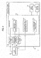
- Fig. 4 illustrates a configuration of the biological signal measuring system 1 according to this exemplary embodiment.
- the biological signal measuring system I has the configuration in which a cuff 30 is used as an example of the sensor 10 shown in Figs. 1 and 3 .
- the biological signal measuring apparatus 20 includes an inflation pump 24, a pressure sensor 25, and a discharge valve 26 as a specific mode for controlling the pressure of the cuff 30.
- the controller 21 has a blood pressure calculator 213 which noninvasively calculates the blood pressure of the subject, in addition to the blood refill time measuring section 212.
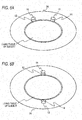
- FIG. 5A is an external view of the cuff 30.
- the cuff 30 is wrapped around the upper arm or the lower limb to be fixed thereto, in a similar manner as typical cuffs for non-invasive measurement.
- the cuff 30 has a hook-and-loop fastener 31 on the contact surface 16 that contacts the subject, and another hook-and-loop fastener 32 on a surface opposite to the contact surface 16.
- fibers are raised in a hook manner, and, in the other fastener, fibers are densely raised in a loop manner.
- the hook-and-loop fasteners 31, 32 When the hook-and-loop fasteners 31, 32 are pressed against each other, the cuff can be secured to the subject.
- the hook-and-loop fasteners 31, 32 may be provided in another form such as a click type fastener or a shark bite fastener as far as the cuff can be secured to the subject.
- the cuff 30 is connected to the biological signal measuring apparatus 20 through a tube 33.
- an adhesive member such as an adhesive tape may be used in the place where the hook-and-loop fastener 31 is disposed, and the cuff 30 may be secured to the subject.
- Fig. 5B is a front view of the contact surface 16 of the cuff 30 (the side on which the cuff 30 contacts a surface of a body of a subject).
- a bag 34 is placed so as to cover the light emitter 11 and the light receiver 13.
- the bag 34 corresponds to the light blocking member 15 in Fig. 3 . That is, the bag 34 has also the function of blocking light passing between the light emitter 11 and the light receiver 13. Therefore, the bag 34 is a bag which is made of a material such as colored polyvinyl chloride or polyurethane, and into which gas (mainly air) can be flown (charged).
- An air inflow control is performed on the bag 34 by the biological signal measuring apparatus 20. When gas is sent into the bag 34, the bag is inflated, and compresses the living tissue of the subject.
- Figs. 6A and 6B are views showing the concept of the attachment of the cuff 30.
- Fig. 6A is a conceptual view showing the cuff 30 of the reflection type.
- the light receiver 13 receives light (reflected light) which is emitted by the light emitter 11 and then reflected from the living tissue.
- Fig. 6B shows an example of attachment of the cuff 30 in which the light emitter 11 and the light receiver 13 are substantially opposed to each other across the living tissue.
- the light receiver 13 receives light (transmitted light) which is emitted by the light emitter 11 and then transmitted through the living tissue.
- the inflation pump 24, the pressure sensor 25, and the discharge valve 26 perform the pressure rise/fall of the cuff 30 and detect the cuff pressure.
- the inflation pump 24 is a low-flow-rate air pump such as a rolling pump having a plurality of cylinders.
- the pressure sensor 25 detects the air pressure (cuff pressure) in the cuff 30.
- An oscillation signal indicating the detected cuff pressure is processed in an A/D converter (not shown) and the like, and is then sent to the pressure adjusting section 211 and the blood pressure calculator 213.
- the discharge valve 26 is driven to discharge the gas (mainly air) in the cuff 30.
- the blood pressure calculator 213 calculates the blood pressure of the subject based on the displacement of the oscillation signal.
- the blood pressure calculator 213 is configured to performs a non-invasive blood pressure measurement by linear inflation method.
- the non-invasive blood pressure measurement by linear inflation method may be implemented by, for example, a system similar to that disclosed in JP2012-40088A or Nihon Kohden's website "Bedside Monitor BSM-1700 series - Life Scope PT", accessible as of September 22, 2014 at www.nihonkohden.co.jp/iryo/products/monitor/01_bedside/bsm1700.html,.
- the pressure adjusting section 211 raises the cuff pressure to a first set value.
- the blood pressure calculator 213 identifies the systolic blood pressure and the diastolic blood pressure by using the oscillation signal which is varied in accordance with the pressure rise. In the case where both the identified systolic and diastolic blood pressures are normal values, the pressure adjusting section 211 terminates the pressure rise of the cuff 30, and immediately releases the cuff pressure.
- the pressure adjusting section 211 raises the cuff pressure to a second set value, and then lowers the pressure.
- the blood pressure calculator 213 identifies the blood pressure based on a change of the oscillation signal during the falling. As for the details of the linear inflation method, see, e.g., Figs. 2 and 3 of JP2012-40088A .
- Fig. 7 is a conceptual view showing relationships between a rise of the cuff pressure and the oscillation signal before the cuff pressure reaches the first set value.
- the blood pressure calculator 213 detects a change point TL where the oscillation amplitude is rapidly increased, as the diastolic blood pressure (minimal blood pressure).
- the blood pressure calculator 213 detects a change point TH where the oscillation amplitude is gradually reduced after the amplitude becomes maximum, and rapidly lowered, as the systolic blood pressure (maximal blood pressure).
- deflation of the cuff is started (TX).
- the biological signal measuring apparatus 20 measures also the blood refill time.
- the cuff 30 measures the amount of light received from the living tissue before the rise of the cuff pressure (corresponding to S12 of Fig. 2 ).
- the cuff 30 measures the amount of light received from the living tissue during the pressure rise (corresponding to S14 of Fig. 2 ).
- the blood refill time measuring section 212 computes or calculates the time elapsed from the timing when the living tissue is released from pressure (timing when the cuff pressure is released, corresponding to TX of Fig.
- the blood refill time (corresponding to S16 of Fig. 2 ).
- data for the blood pressure measurement may be acquired after starting the inflation, and the blood refill time may be measured after acquiring the data for the blood pressure measurement. That is, the biological signal measuring apparatus 20 may calculate the blood pressure and the blood refill time after the inflation (i.e., after acquiring the necessary data), or may sequentially calculate the blood pressure during the inflation.
- the biological signal measuring apparatus 20 is configured to calculate the blood refill time of the subject based on the amount of received light acquired by the cuff 30 (i.e., by the sensor 10), and to calculate the blood pressure of the subject based on the pressure change acquired by the cuff 30 (i.e., by the sensor 10).
- the biological signal measuring apparatus 20 may be configured to always calculate the blood refill time and the blood pressure, or may perform calculation (measurement of only the blood refill time, measurement of only the blood pressure, or measurement of the blood refill time and the blood pressure) in accordance with a mode setting by a user (e.g., setting by an operation of a button). With the configuration that allows the mode setting, a measurement that is required in accordance with the condition of the subject can be performed, and the measurement time can be shortened by not performing an unnecessary measurement.
- At least one of the timing of measuring the blood pressure and the timing of measuring the blood refill time be set optionally by the user. That is, only the timing of measuring the blood pressure, only the timing of measuring the blood refill time, or both of the timing of measuring the blood pressure and the timing of measuring the blood refill time may be set. For example, the user may perform setting so that the blood pressure is measured every 30 minutes, and the blood refill time is measured every one hour.
- the biological signal measuring system 1 automatically controls measurements of parameters in accordance with the setting.
- the cuff 30 and biological signal measuring system I of the embodiment will be described.
- the blood flow is caused not to correctly reflect the operation of the central circulation, by an influence of the temperature of the nervous system.
- the blood flow in a portion such as the upper arm or the lower limb is less affected by the temperature and the activity of the nervous system, as compared to the fingertip.
- the cuff 30 has a usual cuff shape ( Figs. 5A and 5B ) for the non-invasive blood pressure measurement, and therefore can be rapidly attached to the upper arm or lower limb of the subject.
- the measurement When the measurement is performed on the upper arm or the lower limb, it is possible to measure the blood refill time to which the condition of the central circulation is reflected. Since the measurement place can be set in the upper arm or the lower limb, the blood refill time can be correctly measured even when the body size of the subject is small (for example, when the subject is a child).
- gas mainly air
- the cuff 30 compresses the living tissue, and then the pressure is released by discharging the gas.
- This operation is substantially the same as that of the cuff in non-invasive blood pressure measurement. Therefore, the biological signal measuring apparatus 20 can perform the non-invasive blood pressure measurement in addition to the measurement of the blood refill time.
- the two parameters can be measured, and therefore the burden on the subject can be reduced.
- the single biological signal measuring apparatus 20 can measure the two parameters, and therefore cost reduction and miniaturization of the apparatus can be realized.
- the biological signal measuring apparatus 20 may be configured to perform a linear inflation non-invasive blood pressure measurement as disclosed in JP2012-40088A ( Fig. 7 ).
- the blood pressure and the blood refill time may be measured at the same timing.
- the biological signal measuring apparatus 20 can measure the blood pressure in a time period which is shorter than that in the case of the usual blood pressure measuring system (the system in which the cuff pressure is firstly raised to a sufficiently high pressure, and, while then lowering the cuff pressure, the oscillation signal is acquired).
- the biological signal measuring apparatus 20 starts the measurement of the blood refill time at the timing when the pressure lowering is started. Since the pressure raising time can be made short, the biological signal measuring apparatus 20 can end also the measurement of the blood refill time in a short time period.
- the blood pressure is calculated by using the usual blood pressure measuring system (the system in which the cuff pressure is firstly raised to a sufficiently high pressure, and, while then lowering the cuff pressure, the oscillation signal is acquired).
- the blood pressure and the blood refill time can be automatically acquired without performing starting operations on buttons and the like each time.
- the timing of measuring the blood pressure e.g., when the blood pressure is measured every 30 minutes, the blood refill time is measured every 30 minutes or every one hour
- the two parameters can be simultaneously measured in a single step of performing the pressure raising and falling on the living tissue, so that the burden on the subject can be reduced.
- both of the blood pressure and the blood refill time are measured in accordance with the pressure control performed on the cuff 30.
- the invention is not limited to this.
- the cuff 30 and the biological signal measuring apparatus 20 may be configured as a single-function apparatus which is used only for measuring the blood refill time.
- the biological signal measuring apparatus 20 detects the pulsation of the cuff pressure in the process of pressurizing, and calculates the maximal blood pressure from the pulsation in a technique similar to that disclosed in JP2012-40088A .
- the biological signal measuring apparatus 20 may end the pressure rise at the timing when the cuff pressure becomes higher than the maximal blood pressure, immediately start the pressure fall, and begin the measurement of the blood refill time. In this case, the time period of the pressure rise and pressure required for measuring the blood refill time can be reduced to the minimum necessary level. Therefore, the blood refill time can be measured without imposing excessive pressure on a subject with low blood pressure.
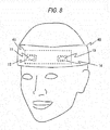
- the senor 10 ( Fig. 3 ) is in a form of a band (a band sensor 40), and is wrapped around a head or the like in use.
- Fig. 8 illustrates an example of an attachment of the band sensor 40
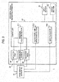
- Fig. 9 illustrates another example of a configuration of the biological signal measuring system 1.
- the band sensor 40 is configured such that the band sensor 40 is attached to a head or the like of a subject by being wrapped around the head or the like of the subject.
- the surface of the band sensor 40 contacting the subject corresponds to the contact surface 16 in Fig. 3 .
- the light emitter 11 in the embodiment emits light of a plurality of wavelengths.
- the light emitter 11 includes a light emitting device which emits red light having a wavelength of about 660 nm, and another light emitting device which emits infrared light having a wavelength of about 940 nm.
- the light receiver 13 receives reflected or transmitted light of the wavelengths (660 nm and 940 nm). The light receiver 13 sends information on amounts of received light of the respective wavelengths to the biological signal measuring apparatus 20.
- the band sensor 40 has inside a bag 41.
- the bag When gas is sent into the bag 41, the bag is inflated, and, in the inflated condition, applies pressure on the living tissue of the subject.
- the air is sent into the bag 41 through a tube which is not shown, from the biological signal measuring apparatus 20.
- the band sensor 40 may be configured by, for example, attaching the bag 41, the light emitter 11, the light receiver 13, and the like to a member such as a band.
- the member functions as the light blocking member 15 in Fig. 3 .
- the user may extend or contract the member in accordance with the attachment place of the subject.
- the band sensor 40 may operate as an SpO2 sensor and also as a sensor for measuring the blood refill time.
- the user operates the input section 22 to designate the measurement mode (an SpO2 measurement mode, a blood refill time measurement mode, or a mode of measurement of the both parameters).
- the measurement mode an SpO2 measurement mode, a blood refill time measurement mode, or a mode of measurement of the both parameters.
- the light receiver 13 detects the amounts of received light of the two wavelengths, and a pulse wave, and sends the result of the detection to the biological signal measuring apparatus 20.
- the band sensor 40 detects the amounts of received light before and after the application of pressure in a manner similar to the example of the cuff 30, and sends the result of the detection to the biological signal measuring apparatus 20.
- the biological signal measuring apparatus 20 which is to be connected to the band sensor 40 will be described with reference to Fig. 9 .
- the biological signal measuring apparatus 20 has an SpO2 calculator 214 in place of the blood pressure calculator 213.
- the SpO2 calculator 214 measures the arterial oxygen saturation (Spo2) based on the pule wave and amounts of received light of the wavelengths (the red light and the infrared light) which are detected by the band sensor 40.
- a calculation of the arterial oxygen saturation by the SpO2 calculator 214 is the same as the calculation using a pulse oximeter (see, e.g., JP6-30915A ).
- the blood refill time measuring section 212 performs the process shown in Fig. 2 to measure the blood refill time.
- the invention is not limited to this.
- a configuration where light of three or more wavelengths is emitted may be employed.
- the band sensor 40 has the configuration where an expandable band is used, the sensor can be attached to various locations on a subject. Therefore, like the example of the cuff, it is useful also in the case where the subject is a child or the like, and can measure the blood refill time to which the condition of the central circulation is reflected.
- the light emitter 11 emits light of two or more wavelengths, and the light receiver 13 receives light.
- the configuration is identical with that of a usual pulse oximeter, and therefore the blood refill time and the arterial oxygen saturation can be measured by using one identical apparatus.
- the band sensor 40 is provided as two parts (a thin-film sheet 42 and a holding band 43).
- the thin-film sheet 42 is configured to contact the surface of the living tissue of the subject, and forms a sheet structure as shown in Fig. 3 .
- the material of the thin-film sheet 42 has a light blocking property. That is, the thin-film sheet 42 functions as the light blocking member 15 that blocks the direct light transmission between the light emitter 11 and the light receiver 13.
- the holding band 43 has the bag 41, and holds the thin-film sheet 42 and the bag 41 onto the subject.
- the holding band 43 is provided in a form of a band like the example of Fig. 8 .
- the thin-film sheet 42 and the holding band 43 are connected to the biological signal measuring apparatus 20 through a tube and wiring which are not shown.
- the blood refill time of the subject who is a child or the like can be correctly measured, and a correct measurement value of the blood refill time to which the condition of the central circulation is reflected can be obtained.
- the holding band 43 is merely an example of a holding member, which may not be in a form of a band.
- the thin-film sheet 42 may be configured such that it is attached to a non-flat portion of a body of a subject, like a finger or the like.
- a holding member having an air bag may be attached on the thin-film sheet 42 so that pressure is applied to the living tissue by inflating the air bag.
- the contact surface 16 of the sensor 10 may have adhesiveness, so that the sensor 10 is attached to a subject by the contact surface 16 adhered to the subject.
- Figs. 11A and 11B are views of a patch sensor 50 as another example of the sensor 10 shown in Fig. 3 .
- Fig. 11A is an external view of the patch sensor 50
- Fig. 11B is a sectional view of the patch sensor 50 taken along the line A-A in Fig. 11A .
- the configuration of the patch sensor 50 will be described with reference to both Figs. 11A and 11B .
- the configuration of the biological signal measuring apparatus 20 is substantially identical with the configurations shown in Figs. 4 and 9 , and therefore its illustration and detailed description are omitted.
- the contact surface 16 of the patch sensor 50 is provided by an adhesive material which can be adhered to the subject.
- the contact surface 16 may be formed by a adhesive agent which is known as a medical adhesive agent. More specifically, an acrylic-based adhesive agent, a rubber-based adhesive agent, a silicone-based adhesive agent, a vinyl ether-based adhesive agent, and the like may be used as it is or mixed with each other.
- the light emitter 11 emits light of a predetermined wavelength to the living tissue.
- the light emitted by the light emitter 11 passes through the first light transmitting member 12 and enters the living tissue.
- the light receiver 13 receives light (reflected light or transmitted light) from the living tissue through the second light transmitting member 14.
- the biological signal measuring apparatus 20 causes gas (mainly air) to be flown into a bag 51 through a tube 52, thereby performing pressure rise and fall on the living tissue.
- the bag 51 functions as the light blocking member 15 in Fig. 3 , and further applies and releases pressure on the living tissue.
- the bag 51 may be placed so as to be interposed between the contact surface 16 and an elastic film 53.
- the elastic film 53 is made of a material having a greater elastic modulus than that of the bag 51. With the elastic film 53 having greater elastic modulus than the bag 51, a force due to the inflation of the bag 51 is efficiently applied toward the living tissue. This enables efficient application of pressure on the living tissue.
- the method of measuring the blood refill time is the same as the previously described examples.
- the patch sensor 50 can be easily pasted to the subject by using a usual adhesive member (acrylic-based adhesive agent or the like). Moreover, the patch sensor 50 can be attached to various locations on the subject. Therefore, the blood refill time can be measured irrespective of situations such as injury or sickness, clothing, or the like of the subject. Like to the example of the cuff, it is useful also in a case where the subject is a child or the like, and can measure the blood refill time to which the condition of the central circulation is reflected.
- the cuff 30 of Fig. 5 may emit light of a plurality of wavelengths.
- the cuff 30 may be configured so as to emit light having wavelengths of about 660 nm, 940 nm, and 1,300 nm.
- the light of 1,300 nm is more largely absorbed by water than hemoglobin.
Landscapes
- Health & Medical Sciences (AREA)
- Life Sciences & Earth Sciences (AREA)
- Cardiology (AREA)
- Surgery (AREA)
- Heart & Thoracic Surgery (AREA)
- Veterinary Medicine (AREA)
- Physics & Mathematics (AREA)
- Public Health (AREA)
- Biophysics (AREA)
- Pathology (AREA)
- Engineering & Computer Science (AREA)
- Biomedical Technology (AREA)
- General Health & Medical Sciences (AREA)
- Medical Informatics (AREA)
- Molecular Biology (AREA)
- Animal Behavior & Ethology (AREA)
- Physiology (AREA)
- Vascular Medicine (AREA)
- Dentistry (AREA)
- Ophthalmology & Optometry (AREA)
- Hematology (AREA)
- Measurement Of The Respiration, Hearing Ability, Form, And Blood Characteristics Of Living Organisms (AREA)
- Measuring Pulse, Heart Rate, Blood Pressure Or Blood Flow (AREA)
Claims (15)
- Sensor (10, 30, 40, 50), der zum Messen einer Blut-Rückfüllzeit (blood refill time) eines lebenden Gewebes eines Patienten ausgeführt ist, wobei der Sensor umfasst:eine Licht-Emissionseinrichtung (11), die zum Emittieren von Licht auf das lebende Gewebe des Patienten zu ausgeführt ist;eine Licht-Empfangseinrichtung (13), die zum Empfangen von reflektiertem Licht oder durchgelassenem Licht von dem lebenden Gewebe des Patienten ausgeführt ist; sowieein Licht-Blockierelement (15), das zum Blockieren von Licht zwischen der Licht-Emissionseinrichtung (11) und der Licht-Empfangseinrichtung (13) ausgeführt ist,einen Druckausübungs-Abschnitt, der einen Beutel (51) umfasst, der so ausgeführt ist, dass er Druck auf das lebende Gewebe des Patienten ausübt, wenn der Beutel aufgeblasen ist;wobei er des Weiteren umfasst:dadurch gekennzeichnet, dass der Beutel (51) das Licht-Blockierelement (15) ist.ein erstes lichtdurchlässiges Element (12), das aus einem lichtdurchlässigen Material besteht, wobei das erste lichtdurchlässige Element (12) ein Ende , das als eine Kontaktfläche ausgeführt ist, die mit der Licht-Emissionseinrichtung (11) in Kontakt kommt, und ein anderes Ende aufweist, das einen Teil einer Kontaktfläche (16) des Sensors (10, 30, 40, 50) bildet, der mit einer Oberfläche des Patienten in Kontakt kommt; sowieein zweites lichtdurchlässiges Element (14), das aus einem lichtdurchlässigen Material besteht wobei das zweite lichtdurchlässige Element (14) ein Ende , das als eine Kontaktfläche ausgeführt ist, die mit der Licht-Empfangseinrichtung (13) in Kontakt kommt, und ein anderes Ende aufweist, das einen anderen Teil der gleichen Kontaktfläche (16) bildet, der mit dem Patienten in Kontakt kommt;
- Sensor (10, 30) nach Anspruch 1, wobei der Sensor (10, 30) als eine Manschette (30) ausgeführt ist, die um den Patienten gewickelt und an dem Patienten gehalten wird.
- Sensor nach Anspruch 1 oder 2, wobei eine Zeitkonstante von Druckreduzierung des Druckausübungs-Abschnitts (34, 41, 51) zwei Sekunden oder weniger beträgt.
- Sensor (10, 30, 50) nach Anspruch 1, wobei die Kontaktfläche (16), die mit dem Patienten in Kontakt kommt, ein klebendes Material umfasst.
- Sensor (10, 50) nach Anspruch 4,wobei der Sensor (10, 50) des Weiteren eine elastische Folie (53) umfasst, die an einer der Kontaktfläche (16) gegenüberliegenden Fläche vorhanden ist, um den Beutel (51) abzudecken, undein Elastizitätsmodul der elastischen Folie (53) größer ist als ein Elastizitätsmodul des Beutels (51).
- Sensor (10, 30, 40, 50) nach einem der Ansprüche 1 bis 4, wobei die Licht-Emissionseinrichtung (11) zum Emittieren von Licht mit zwei oder mehr Wellenlängen ausgeführt ist.
- Sensor (40) nach Anspruch 1, der des Weiteren ein Halteelement (43) umfasst, an dem sich der Druckausübungs-Abschnitt (41) befindet,wobei das Licht-Blockierelement (15) eine Dünnschichtfolie (42) umfasst, auf der die Licht-Emissionseinrichtung (11) und die Licht-Empfangseinrichtung (13) vorhanden sind;und das Halteelement (43) zum Halten der Dünnschichtfolie (42) und des Druckausübungs-Abschnitts (41) an dem Patienten ausgeführt ist.
- Sensor (40) nach Anspruch 1, wobei der Sensor (40) eine Folienstruktur hat, und
das Licht-Blockierelement (15) eine Dünnschichtfolie (42) umfasst, die so ausgeführt ist, dass sie Licht zwischen der Licht-Emissionseinrichtung (11) und der Licht-Empfangseinrichtung (13) blockiert, wobei die Licht-Emissionseinrichtung (11) und die Licht-Empfangseinrichtung (13) auf der Dünnschichtfolie (42) vorhanden sind. - System (1) zum Messen biologischer Signale, das umfasst:
den Sensor (10, 30, 40, 50) nach einem der Ansprüche 1 bis 8, sowie eine Vorrichtung (20) zum Messen biologischer Signale, die so ausgeführt ist, dass sie die Blut-Rückfüllzeit des Patienten auf Basis einer durch den Sensor (10, 30, 40, 50) empfangenen Lichtmenge berechnet. - System (1) zum Messen biologischer Signale, das umfasst:den Sensor (10, 30) nach Anspruch 2; sowieeine Vorrichtung (20) zum Messen biologischer Signale, die so ausgeführt ist, dass sie die Blut-Rückfüllzeit des Patienten auf Basis einer durch den Sensor (10, 30) empfangenen Lichtmenge berechnet und einen Blutdruck des Patienten auf Basis einer durch den Sensor (10, 30) erfassten Druckänderung innerhalb der Manschette (30) berechnet.
- System (1) zum Messen biologischer Signale nach Anspruch 10, wobei die Vorrichtung (20) zum Messen biologischer Signale so ausgeführt ist, dass sie die Blut-Rückfüllzeit des Patienten oder/und den Blutdruck des Patienten mittels Modus-Umschaltung berechnet.
- System (1) zum Messen biologischer Signale nach Anspruch 10 oder 11, wobei die Vorrichtung (20) zum Messen biologischer Signale so ausgeführt ist, dass sie die Blut-Rückfüllzeit des Patienten mit einer Zeittaktung misst, die eingestellt worden ist.
- System (1) zum Messen biologischer Signale nach einem der Ansprüche 10 bis 12, wobei die Vorrichtung zum Messen biologischer Signale (20) so ausgeführt ist, dass sie den Blutdruck des Patienten mit einer Zeittaktung misst, die eingestellt worden ist.
- System (1) zum Messen biologischer Signale nach Anspruch 10 oder 11, wobei die Vorrichtung (20) zum Messen biologischer Signale beginnt, für eine Berechnung des Blutdrucks des Patienten zu verwendende Daten zu erfassen, nachdem der Sensor eine Ausübung von Druck auf das lebende Gewebe des Patienten beginnt, die Ausübung von Druck auf das lebende Gewebe des Patienten beendet, nachdem Erfassen der für die Berechnung des Blutdrucks zu verwendenden Daten beendet ist, und beginnt, die Blut-Rückfüllzeit des Patienten unter Verwendung einer Änderung einer Menge an empfangenem Licht zu messen, nachdem die Ausübung von Druck beendet ist.
- Sensor (10, 30, 40, 50) nach Anspruch 1, wobei das lichtdurchlässige Material des ersten lichtdurchlässigen Elementes (12) und das lichtdurchlässige Material des zweiten lichtdurchlässigen Elementes (14) einen ersten Lichtdurchlassgrad aufweisen, und
das Licht-Blockierelement (15) einen zweiten Lichtdurchlassgrad aufweist, der niedriger ist als der erste Lichtdurchlassgrad.
Applications Claiming Priority (2)
| Application Number | Priority Date | Filing Date | Title |
|---|---|---|---|
| JP2014198149 | 2014-09-29 | ||
| JP2015175300A JP2016067916A (ja) | 2014-09-29 | 2015-09-07 | センサ及び生体信号測定システム |
Publications (2)
| Publication Number | Publication Date |
|---|---|
| EP3000388A1 EP3000388A1 (de) | 2016-03-30 |
| EP3000388B1 true EP3000388B1 (de) | 2022-01-12 |
Family
ID=54147082
Family Applications (1)
| Application Number | Title | Priority Date | Filing Date |
|---|---|---|---|
| EP15185419.7A Active EP3000388B1 (de) | 2014-09-29 | 2015-09-16 | Sensor und system zur messung biologischer signale |
Country Status (2)
| Country | Link |
|---|---|
| US (1) | US10117585B2 (de) |
| EP (1) | EP3000388B1 (de) |
Families Citing this family (7)
| Publication number | Priority date | Publication date | Assignee | Title |
|---|---|---|---|---|
| US5208212A (en) | 1988-08-31 | 1993-05-04 | Fmc Corporation | Herbicidal compositions containing triazolinones |
| US11350837B2 (en) * | 2016-03-30 | 2022-06-07 | Elfi-Tech Ltd. | Method and apparatus for optically measuring blood pressure |
| US11134901B2 (en) * | 2016-03-30 | 2021-10-05 | Elfi-Tech Ltd. | Method and apparatus for optically measuring blood pressure |
| US12156721B2 (en) * | 2016-03-30 | 2024-12-03 | Elfi-Tech Ltd. | Method and apparatus for optically measuring blood pressure |
| RU2637102C1 (ru) * | 2016-09-15 | 2017-11-29 | Государственное бюджетное учреждение здравоохранения Московской области "Московский областной научно-исследовательский клинический институт им. М.Ф. Владимирского" (ГБУЗ МО МОНИКИ им. М.Ф. Владимирского) | Устройство для спектрофотометрической оценки уровня кровенаполнения поверхностных слоев тканей и органов человека in vivo |
| WO2018144963A1 (en) * | 2017-02-06 | 2018-08-09 | Gnotrix, Llc | Apparatus and methods of sensing a patient condition, such as anatomy position, and of controlling patient applications |
| CN113520307B (zh) * | 2020-04-20 | 2023-04-18 | 华为技术有限公司 | 一种可穿戴设备 |
Citations (1)
| Publication number | Priority date | Publication date | Assignee | Title |
|---|---|---|---|---|
| EP2449965B1 (de) * | 2010-11-09 | 2018-09-12 | Nihon Kohden Corporation | Vorrichtung zum Messen biologischer Signale und Verfahren zum Messen biologischer Signale |
Family Cites Families (16)
| Publication number | Priority date | Publication date | Assignee | Title |
|---|---|---|---|---|
| US3040737A (en) * | 1959-12-10 | 1962-06-26 | Honeywell Regulator Co | Blood pressure measuring transducer |
| US3906937A (en) * | 1972-10-25 | 1975-09-23 | Para Medical Instr Corp | Blood pressure cuff and bladder and apparatus embodying the same |
| US4846189A (en) * | 1987-06-29 | 1989-07-11 | Shuxing Sun | Noncontactive arterial blood pressure monitor and measuring method |
| US5385143A (en) | 1992-02-06 | 1995-01-31 | Nihon Kohden Corporation | Apparatus for measuring predetermined data of living tissue |
| JP2608830B2 (ja) | 1992-03-19 | 1997-05-14 | 日本光電工業株式会社 | 組織内ヘモグロビン量測定装置 |
| WO2007086071A2 (en) * | 2006-01-30 | 2007-08-02 | Cardiosense Ltd. | Apparatus, system and method for determining cardio-respiratory state |
| US8082017B2 (en) | 2006-06-02 | 2011-12-20 | The General Electric Company | Method and apparatus for measuring capillary refill time and carrying out pulse oximetry with a single device |
| WO2009043028A2 (en) * | 2007-09-28 | 2009-04-02 | Tiax Llc | Measurement of physiological signals |
| WO2009053920A1 (en) * | 2007-10-25 | 2009-04-30 | Koninklijke Philips Electronics N.V. | Monitoring the degree of hydration of the human body |
| JP5056867B2 (ja) * | 2009-07-01 | 2012-10-24 | カシオ計算機株式会社 | 生体情報検出装置および生体情報検出方法 |
| JP5536586B2 (ja) | 2010-08-17 | 2014-07-02 | 日本光電工業株式会社 | 血圧測定装置 |
| US9049998B2 (en) * | 2012-06-22 | 2015-06-09 | Fitbit, Inc. | Biometric monitoring device with heart rate measurement activated by a single user-gesture |
| JP6251997B2 (ja) * | 2012-09-18 | 2017-12-27 | カシオ計算機株式会社 | 脈拍データ検出装置、脈拍データ検出方法、および脈拍データ検出プログラム |
| JP6148869B2 (ja) | 2013-01-31 | 2017-06-14 | 日本光電工業株式会社 | 生体信号測定システム、生体信号測定装置、および生体信号測定装置の制御プログラム |
| US20140275891A1 (en) | 2013-03-13 | 2014-09-18 | Cephalogics, LLC | Optical tomography sensor and related apparatus and methods |
| CN104055505B (zh) | 2013-03-18 | 2019-03-22 | 精工爱普生株式会社 | 生物体信息检测装置 |
-
2015
- 2015-09-13 US US14/852,587 patent/US10117585B2/en active Active
- 2015-09-16 EP EP15185419.7A patent/EP3000388B1/de active Active
Patent Citations (1)
| Publication number | Priority date | Publication date | Assignee | Title |
|---|---|---|---|---|
| EP2449965B1 (de) * | 2010-11-09 | 2018-09-12 | Nihon Kohden Corporation | Vorrichtung zum Messen biologischer Signale und Verfahren zum Messen biologischer Signale |
Also Published As
| Publication number | Publication date |
|---|---|
| US10117585B2 (en) | 2018-11-06 |
| US20160089036A1 (en) | 2016-03-31 |
| EP3000388A1 (de) | 2016-03-30 |
Similar Documents
| Publication | Publication Date | Title |
|---|---|---|
| US10117585B2 (en) | Sensor and biological signal measuring system | |
| US10226183B2 (en) | Devices and methods for temperature determination | |
| JP5425468B2 (ja) | 使い捨てパルス酸素濃度計 | |
| US8700116B2 (en) | Sensor system with pressure application | |
| EP3697291B1 (de) | Am körper tragbares blutdruckmessgerät und methode | |
| FI127170B (en) | Portable biometric device and method of making it | |
| JP4739126B2 (ja) | 酸素飽和度計測装置、酸素飽和度計測装置の制御プログラム、および酸素飽和度計測装置の制御プログラムが記録された記録媒体 | |
| US20180235489A1 (en) | Photoplethysmographic wearable blood pressure monitoring system and methods | |
| CN107847190A (zh) | 用于保持生理传感器的用具 | |
| US20170273579A1 (en) | Blood pressure estimation apparatus, sphygmomanometer, blood pressure estimation system, and blood pressure estimation method | |
| CN102525444A (zh) | 生物信号测量装置以及生物信号测量方法 | |
| JP2006239114A (ja) | カフレス電子血圧計 | |
| EP3028630B1 (de) | Messsystem zur beurteilung des zustandes eines patienten | |
| EP2214551B1 (de) | Messung der sauerstoffsättigung von bluthämoglobin | |
| US20260060559A1 (en) | Apparatus and method for measuring blood pressure via a finger | |
| JP2009082627A (ja) | 生体情報測定装置 | |
| US9597031B2 (en) | Lymphatic pressure-measuring system and method for controlling same | |
| US11020010B2 (en) | Blood pressure/pulse wave measurement device | |
| KR100800075B1 (ko) | 심박수 산출 방법 및 심박수 측정 장치 | |
| JP6622861B2 (ja) | 測定システム、及び測定装置 | |
| JP2016067916A (ja) | センサ及び生体信号測定システム | |
| US20230301531A1 (en) | Apparatus and methods for triggering blood pressure measurements | |
| JPH0221844A (ja) | 血圧計プローブ及び血圧測定装置 | |
| JPH0565177B2 (de) |
Legal Events
| Date | Code | Title | Description |
|---|---|---|---|
| PUAI | Public reference made under article 153(3) epc to a published international application that has entered the european phase |
Free format text: ORIGINAL CODE: 0009012 |
|
| AK | Designated contracting states |
Kind code of ref document: A1 Designated state(s): AL AT BE BG CH CY CZ DE DK EE ES FI FR GB GR HR HU IE IS IT LI LT LU LV MC MK MT NL NO PL PT RO RS SE SI SK SM TR |
|
| AX | Request for extension of the european patent |
Extension state: BA ME |
|
| 17P | Request for examination filed |
Effective date: 20160928 |
|
| RBV | Designated contracting states (corrected) |
Designated state(s): AL AT BE BG CH CY CZ DE DK EE ES FI FR GB GR HR HU IE IS IT LI LT LU LV MC MK MT NL NO PL PT RO RS SE SI SK SM TR |
|
| STAA | Information on the status of an ep patent application or granted ep patent |
Free format text: STATUS: EXAMINATION IS IN PROGRESS |
|
| 17Q | First examination report despatched |
Effective date: 20170126 |
|
| 17Q | First examination report despatched |
Effective date: 20170215 |
|
| GRAP | Despatch of communication of intention to grant a patent |
Free format text: ORIGINAL CODE: EPIDOSNIGR1 |
|
| STAA | Information on the status of an ep patent application or granted ep patent |
Free format text: STATUS: GRANT OF PATENT IS INTENDED |
|
| RIC1 | Information provided on ipc code assigned before grant |
Ipc: A61B 5/00 20060101ALN20210908BHEP Ipc: A61B 5/024 20060101ALN20210908BHEP Ipc: A61B 5/02 20060101ALI20210908BHEP Ipc: A61B 5/022 20060101ALI20210908BHEP Ipc: A61B 5/026 20060101AFI20210908BHEP |
|
| INTG | Intention to grant announced |
Effective date: 20210920 |
|
| GRAS | Grant fee paid |
Free format text: ORIGINAL CODE: EPIDOSNIGR3 |
|
| GRAA | (expected) grant |
Free format text: ORIGINAL CODE: 0009210 |
|
| STAA | Information on the status of an ep patent application or granted ep patent |
Free format text: STATUS: THE PATENT HAS BEEN GRANTED |
|
| AK | Designated contracting states |
Kind code of ref document: B1 Designated state(s): AL AT BE BG CH CY CZ DE DK EE ES FI FR GB GR HR HU IE IS IT LI LT LU LV MC MK MT NL NO PL PT RO RS SE SI SK SM TR |
|
| REG | Reference to a national code |
Ref country code: GB Ref legal event code: FG4D |
|
| REG | Reference to a national code |
Ref country code: CH Ref legal event code: EP |
|
| REG | Reference to a national code |
Ref country code: DE Ref legal event code: R096 Ref document number: 602015076392 Country of ref document: DE |
|
| REG | Reference to a national code |
Ref country code: IE Ref legal event code: FG4D |
|
| REG | Reference to a national code |
Ref country code: AT Ref legal event code: REF Ref document number: 1461854 Country of ref document: AT Kind code of ref document: T Effective date: 20220215 |
|
| REG | Reference to a national code |
Ref country code: LT Ref legal event code: MG9D |
|
| REG | Reference to a national code |
Ref country code: NL Ref legal event code: MP Effective date: 20220112 |
|
| REG | Reference to a national code |
Ref country code: AT Ref legal event code: MK05 Ref document number: 1461854 Country of ref document: AT Kind code of ref document: T Effective date: 20220112 |
|
| PG25 | Lapsed in a contracting state [announced via postgrant information from national office to epo] |
Ref country code: NL Free format text: LAPSE BECAUSE OF FAILURE TO SUBMIT A TRANSLATION OF THE DESCRIPTION OR TO PAY THE FEE WITHIN THE PRESCRIBED TIME-LIMIT Effective date: 20220112 |
|
| PG25 | Lapsed in a contracting state [announced via postgrant information from national office to epo] |
Ref country code: SE Free format text: LAPSE BECAUSE OF FAILURE TO SUBMIT A TRANSLATION OF THE DESCRIPTION OR TO PAY THE FEE WITHIN THE PRESCRIBED TIME-LIMIT Effective date: 20220112 Ref country code: RS Free format text: LAPSE BECAUSE OF FAILURE TO SUBMIT A TRANSLATION OF THE DESCRIPTION OR TO PAY THE FEE WITHIN THE PRESCRIBED TIME-LIMIT Effective date: 20220112 Ref country code: PT Free format text: LAPSE BECAUSE OF FAILURE TO SUBMIT A TRANSLATION OF THE DESCRIPTION OR TO PAY THE FEE WITHIN THE PRESCRIBED TIME-LIMIT Effective date: 20220512 Ref country code: NO Free format text: LAPSE BECAUSE OF FAILURE TO SUBMIT A TRANSLATION OF THE DESCRIPTION OR TO PAY THE FEE WITHIN THE PRESCRIBED TIME-LIMIT Effective date: 20220412 Ref country code: LT Free format text: LAPSE BECAUSE OF FAILURE TO SUBMIT A TRANSLATION OF THE DESCRIPTION OR TO PAY THE FEE WITHIN THE PRESCRIBED TIME-LIMIT Effective date: 20220112 Ref country code: HR Free format text: LAPSE BECAUSE OF FAILURE TO SUBMIT A TRANSLATION OF THE DESCRIPTION OR TO PAY THE FEE WITHIN THE PRESCRIBED TIME-LIMIT Effective date: 20220112 Ref country code: ES Free format text: LAPSE BECAUSE OF FAILURE TO SUBMIT A TRANSLATION OF THE DESCRIPTION OR TO PAY THE FEE WITHIN THE PRESCRIBED TIME-LIMIT Effective date: 20220112 Ref country code: BG Free format text: LAPSE BECAUSE OF FAILURE TO SUBMIT A TRANSLATION OF THE DESCRIPTION OR TO PAY THE FEE WITHIN THE PRESCRIBED TIME-LIMIT Effective date: 20220412 |
|
| PG25 | Lapsed in a contracting state [announced via postgrant information from national office to epo] |
Ref country code: PL Free format text: LAPSE BECAUSE OF FAILURE TO SUBMIT A TRANSLATION OF THE DESCRIPTION OR TO PAY THE FEE WITHIN THE PRESCRIBED TIME-LIMIT Effective date: 20220112 Ref country code: LV Free format text: LAPSE BECAUSE OF FAILURE TO SUBMIT A TRANSLATION OF THE DESCRIPTION OR TO PAY THE FEE WITHIN THE PRESCRIBED TIME-LIMIT Effective date: 20220112 Ref country code: GR Free format text: LAPSE BECAUSE OF FAILURE TO SUBMIT A TRANSLATION OF THE DESCRIPTION OR TO PAY THE FEE WITHIN THE PRESCRIBED TIME-LIMIT Effective date: 20220413 Ref country code: FI Free format text: LAPSE BECAUSE OF FAILURE TO SUBMIT A TRANSLATION OF THE DESCRIPTION OR TO PAY THE FEE WITHIN THE PRESCRIBED TIME-LIMIT Effective date: 20220112 Ref country code: AT Free format text: LAPSE BECAUSE OF FAILURE TO SUBMIT A TRANSLATION OF THE DESCRIPTION OR TO PAY THE FEE WITHIN THE PRESCRIBED TIME-LIMIT Effective date: 20220112 |
|
| PG25 | Lapsed in a contracting state [announced via postgrant information from national office to epo] |
Ref country code: IS Free format text: LAPSE BECAUSE OF FAILURE TO SUBMIT A TRANSLATION OF THE DESCRIPTION OR TO PAY THE FEE WITHIN THE PRESCRIBED TIME-LIMIT Effective date: 20220512 |
|
| REG | Reference to a national code |
Ref country code: DE Ref legal event code: R097 Ref document number: 602015076392 Country of ref document: DE |
|
| PG25 | Lapsed in a contracting state [announced via postgrant information from national office to epo] |
Ref country code: SM Free format text: LAPSE BECAUSE OF FAILURE TO SUBMIT A TRANSLATION OF THE DESCRIPTION OR TO PAY THE FEE WITHIN THE PRESCRIBED TIME-LIMIT Effective date: 20220112 Ref country code: SK Free format text: LAPSE BECAUSE OF FAILURE TO SUBMIT A TRANSLATION OF THE DESCRIPTION OR TO PAY THE FEE WITHIN THE PRESCRIBED TIME-LIMIT Effective date: 20220112 Ref country code: RO Free format text: LAPSE BECAUSE OF FAILURE TO SUBMIT A TRANSLATION OF THE DESCRIPTION OR TO PAY THE FEE WITHIN THE PRESCRIBED TIME-LIMIT Effective date: 20220112 Ref country code: EE Free format text: LAPSE BECAUSE OF FAILURE TO SUBMIT A TRANSLATION OF THE DESCRIPTION OR TO PAY THE FEE WITHIN THE PRESCRIBED TIME-LIMIT Effective date: 20220112 Ref country code: DK Free format text: LAPSE BECAUSE OF FAILURE TO SUBMIT A TRANSLATION OF THE DESCRIPTION OR TO PAY THE FEE WITHIN THE PRESCRIBED TIME-LIMIT Effective date: 20220112 Ref country code: CZ Free format text: LAPSE BECAUSE OF FAILURE TO SUBMIT A TRANSLATION OF THE DESCRIPTION OR TO PAY THE FEE WITHIN THE PRESCRIBED TIME-LIMIT Effective date: 20220112 |
|
| PLBE | No opposition filed within time limit |
Free format text: ORIGINAL CODE: 0009261 |
|
| STAA | Information on the status of an ep patent application or granted ep patent |
Free format text: STATUS: NO OPPOSITION FILED WITHIN TIME LIMIT |
|
| PG25 | Lapsed in a contracting state [announced via postgrant information from national office to epo] |
Ref country code: AL Free format text: LAPSE BECAUSE OF FAILURE TO SUBMIT A TRANSLATION OF THE DESCRIPTION OR TO PAY THE FEE WITHIN THE PRESCRIBED TIME-LIMIT Effective date: 20220112 |
|
| 26N | No opposition filed |
Effective date: 20221013 |
|
| PG25 | Lapsed in a contracting state [announced via postgrant information from national office to epo] |
Ref country code: SI Free format text: LAPSE BECAUSE OF FAILURE TO SUBMIT A TRANSLATION OF THE DESCRIPTION OR TO PAY THE FEE WITHIN THE PRESCRIBED TIME-LIMIT Effective date: 20220112 |
|
| PG25 | Lapsed in a contracting state [announced via postgrant information from national office to epo] |
Ref country code: MC Free format text: LAPSE BECAUSE OF FAILURE TO SUBMIT A TRANSLATION OF THE DESCRIPTION OR TO PAY THE FEE WITHIN THE PRESCRIBED TIME-LIMIT Effective date: 20220112 |
|
| REG | Reference to a national code |
Ref country code: CH Ref legal event code: PL |
|
| GBPC | Gb: european patent ceased through non-payment of renewal fee |
Effective date: 20220916 |
|
| REG | Reference to a national code |
Ref country code: BE Ref legal event code: MM Effective date: 20220930 |
|
| PG25 | Lapsed in a contracting state [announced via postgrant information from national office to epo] |
Ref country code: LU Free format text: LAPSE BECAUSE OF NON-PAYMENT OF DUE FEES Effective date: 20220916 |
|
| PG25 | Lapsed in a contracting state [announced via postgrant information from national office to epo] |
Ref country code: LI Free format text: LAPSE BECAUSE OF NON-PAYMENT OF DUE FEES Effective date: 20220930 Ref country code: IT Free format text: LAPSE BECAUSE OF FAILURE TO SUBMIT A TRANSLATION OF THE DESCRIPTION OR TO PAY THE FEE WITHIN THE PRESCRIBED TIME-LIMIT Effective date: 20220112 Ref country code: IE Free format text: LAPSE BECAUSE OF NON-PAYMENT OF DUE FEES Effective date: 20220916 Ref country code: FR Free format text: LAPSE BECAUSE OF NON-PAYMENT OF DUE FEES Effective date: 20220930 Ref country code: CH Free format text: LAPSE BECAUSE OF NON-PAYMENT OF DUE FEES Effective date: 20220930 |
|
| PG25 | Lapsed in a contracting state [announced via postgrant information from national office to epo] |
Ref country code: BE Free format text: LAPSE BECAUSE OF NON-PAYMENT OF DUE FEES Effective date: 20220930 |
|
| PG25 | Lapsed in a contracting state [announced via postgrant information from national office to epo] |
Ref country code: GB Free format text: LAPSE BECAUSE OF NON-PAYMENT OF DUE FEES Effective date: 20220916 |
|
| PG25 | Lapsed in a contracting state [announced via postgrant information from national office to epo] |
Ref country code: HU Free format text: LAPSE BECAUSE OF FAILURE TO SUBMIT A TRANSLATION OF THE DESCRIPTION OR TO PAY THE FEE WITHIN THE PRESCRIBED TIME-LIMIT; INVALID AB INITIO Effective date: 20150916 |
|
| PG25 | Lapsed in a contracting state [announced via postgrant information from national office to epo] |
Ref country code: CY Free format text: LAPSE BECAUSE OF FAILURE TO SUBMIT A TRANSLATION OF THE DESCRIPTION OR TO PAY THE FEE WITHIN THE PRESCRIBED TIME-LIMIT Effective date: 20220112 |
|
| PG25 | Lapsed in a contracting state [announced via postgrant information from national office to epo] |
Ref country code: MK Free format text: LAPSE BECAUSE OF FAILURE TO SUBMIT A TRANSLATION OF THE DESCRIPTION OR TO PAY THE FEE WITHIN THE PRESCRIBED TIME-LIMIT Effective date: 20220112 |
|
| PG25 | Lapsed in a contracting state [announced via postgrant information from national office to epo] |
Ref country code: MT Free format text: LAPSE BECAUSE OF FAILURE TO SUBMIT A TRANSLATION OF THE DESCRIPTION OR TO PAY THE FEE WITHIN THE PRESCRIBED TIME-LIMIT Effective date: 20220112 |
|
| PGFP | Annual fee paid to national office [announced via postgrant information from national office to epo] |
Ref country code: DE Payment date: 20250730 Year of fee payment: 11 |
|
| PG25 | Lapsed in a contracting state [announced via postgrant information from national office to epo] |
Ref country code: TR Free format text: LAPSE BECAUSE OF FAILURE TO SUBMIT A TRANSLATION OF THE DESCRIPTION OR TO PAY THE FEE WITHIN THE PRESCRIBED TIME-LIMIT Effective date: 20220112 |