EP3000299B1 - Distribution device for granular materials - Google Patents
Distribution device for granular materials Download PDFInfo
- Publication number
- EP3000299B1 EP3000299B1 EP15182126.1A EP15182126A EP3000299B1 EP 3000299 B1 EP3000299 B1 EP 3000299B1 EP 15182126 A EP15182126 A EP 15182126A EP 3000299 B1 EP3000299 B1 EP 3000299B1
- Authority
- EP
- European Patent Office
- Prior art keywords
- grains
- metering
- metering device
- drive motor
- sensor unit
- Prior art date
- Legal status (The legal status is an assumption and is not a legal conclusion. Google has not performed a legal analysis and makes no representation as to the accuracy of the status listed.)
- Active
Links
- 239000008187 granular material Substances 0.000 title claims description 22
- 238000000034 method Methods 0.000 claims description 12
- 238000009331 sowing Methods 0.000 claims description 11
- 238000011144 upstream manufacturing Methods 0.000 claims description 7
- 239000003337 fertilizer Substances 0.000 claims description 6
- 239000002689 soil Substances 0.000 claims description 6
- 230000001105 regulatory effect Effects 0.000 claims description 5
- 239000000463 material Substances 0.000 claims description 3
- 238000003860 storage Methods 0.000 claims description 2
- 230000011664 signaling Effects 0.000 claims 1
- 238000013459 approach Methods 0.000 description 2
- 238000001514 detection method Methods 0.000 description 2
- 238000010586 diagram Methods 0.000 description 2
- 238000012544 monitoring process Methods 0.000 description 2
- -1 seeds Substances 0.000 description 2
- 238000010276 construction Methods 0.000 description 1
- 230000001276 controlling effect Effects 0.000 description 1
- 238000013461 design Methods 0.000 description 1
- 238000007599 discharging Methods 0.000 description 1
- 230000000694 effects Effects 0.000 description 1
- 239000012535 impurity Substances 0.000 description 1
- 238000012986 modification Methods 0.000 description 1
- 230000004048 modification Effects 0.000 description 1
- 238000010899 nucleation Methods 0.000 description 1
- 239000002245 particle Substances 0.000 description 1
- 238000010972 statistical evaluation Methods 0.000 description 1
- 239000010902 straw Substances 0.000 description 1
- 230000001502 supplementing effect Effects 0.000 description 1
Images

Classifications
-
- A—HUMAN NECESSITIES
- A01—AGRICULTURE; FORESTRY; ANIMAL HUSBANDRY; HUNTING; TRAPPING; FISHING
- A01C—PLANTING; SOWING; FERTILISING
- A01C7/00—Sowing
- A01C7/08—Broadcast seeders; Seeders depositing seeds in rows
- A01C7/16—Seeders with other distributing devices, e.g. brushes, discs, screws or slides
-
- A—HUMAN NECESSITIES
- A01—AGRICULTURE; FORESTRY; ANIMAL HUSBANDRY; HUNTING; TRAPPING; FISHING
- A01C—PLANTING; SOWING; FERTILISING
- A01C7/00—Sowing
- A01C7/08—Broadcast seeders; Seeders depositing seeds in rows
- A01C7/10—Devices for adjusting the seed-box ; Regulation of machines for depositing quantities at intervals
- A01C7/102—Regulating or controlling the seed rate
-
- A—HUMAN NECESSITIES
- A01—AGRICULTURE; FORESTRY; ANIMAL HUSBANDRY; HUNTING; TRAPPING; FISHING
- A01C—PLANTING; SOWING; FERTILISING
- A01C19/00—Arrangements for driving working parts of fertilisers or seeders
- A01C19/02—Arrangements for driving working parts of fertilisers or seeders by a motor
-
- A—HUMAN NECESSITIES
- A01—AGRICULTURE; FORESTRY; ANIMAL HUSBANDRY; HUNTING; TRAPPING; FISHING
- A01C—PLANTING; SOWING; FERTILISING
- A01C5/00—Making or covering furrows or holes for sowing, planting or manuring
- A01C5/06—Machines for making or covering drills or furrows for sowing or planting
- A01C5/062—Devices for making drills or furrows
-
- A—HUMAN NECESSITIES
- A01—AGRICULTURE; FORESTRY; ANIMAL HUSBANDRY; HUNTING; TRAPPING; FISHING
- A01C—PLANTING; SOWING; FERTILISING
- A01C7/00—Sowing
- A01C7/08—Broadcast seeders; Seeders depositing seeds in rows
- A01C7/10—Devices for adjusting the seed-box ; Regulation of machines for depositing quantities at intervals
- A01C7/102—Regulating or controlling the seed rate
- A01C7/105—Seed sensors
-
- A—HUMAN NECESSITIES
- A01—AGRICULTURE; FORESTRY; ANIMAL HUSBANDRY; HUNTING; TRAPPING; FISHING
- A01C—PLANTING; SOWING; FERTILISING
- A01C7/00—Sowing
- A01C7/04—Single-grain seeders with or without suction devices
-
- A—HUMAN NECESSITIES
- A01—AGRICULTURE; FORESTRY; ANIMAL HUSBANDRY; HUNTING; TRAPPING; FISHING
- A01C—PLANTING; SOWING; FERTILISING
- A01C7/00—Sowing
- A01C7/08—Broadcast seeders; Seeders depositing seeds in rows
- A01C7/081—Seeders depositing seeds in rows using pneumatic means
Definitions
- the present invention relates to a distribution device for the metering of granular material such as seeds, fertilizer o. The like. With the features of independent claim 1.
- the invention also relates to a method for applying granular-like material, in particular granular seed, fertilizer o. The like., with the features of the independent method claim 5.
- the DE 10 2013 215 183 B3 discloses a method and apparatus for metering granular material such as seeds, fertilizer, etc.
- carried and conveyed by an air flow granular material is passed through a supply line in a metering unit, where an electric motor driven conveyor or fan disc concentrically rotates. Based on a detected torque of the electromotive drive whose drive speed can be increased or reduced.
- each metering unit is preceded by at least one grain flow sensor, which may be located in a supply line or, for example, in a distribution unit such as a distribution tower.
- the data of the grain flow sensor which may typically be formed by a baffle sensor, in particular by a piezoelectrically operating impact sensor, are used to control the speed of the electric drive motor of the metering unit, so that the conveyor or fan disc rotates faster or slower to strong fluctuations in the Grain flow to be able to react better, and to avoid unwanted congestion or blockages due to high grain volume.
- the current drive torque of the electric drive motor is determined or deduced by the fact that its electrical power consumption is measured, as this allows an immediate conclusion to the engine resistance and thus to the expended engine torque.
- the aim of better equalization of the seed applied can be achieved by adjusting the engine speed based on the detected drive torque, whereby larger fluctuations in the application rate of a single meter can be compensated or suppressed in the desired manner.
- the application rates between the individual rows can continue to vary, the goal of the optimized and, if possible, unstable grain spacing within the row is not achieved.
- the feeders are supplied via the already existing air supply of a pneumatic seeder, which typically has a central distributor head with flexible seed lines to the individual coulters.
- a pneumatic seeder typically has a central distributor head with flexible seed lines to the individual coulters.
- all coulters and dosing units are fed as evenly as possible with seed.
- the individual dosers are placed, typically close to the coulters, as the downcomers to the coulters are normally the output lines of the dosers.
- grain sensors for monitoring the quantities of grain discharged from the meter are arranged in the downpipes, so that these sensor values can be used for further control of the drive motors.
- the metering device described is particularly suitable for placement in grain-carrying lines, especially in seed lines of a seeder known per se, in particular one that promotes pneumatic. In each seed line such a metering device can be arranged, where it can ensure a nearly isolated seed distribution.
- the metering device is an attachment suitable for supplementing an existing seed drill and making it a precision seed drill.
- the air flow carries and conveys the granular material during its entire transport from the grain supply to the coulter, wherein the air flow within the metering unit is guided in an approximately circular arc-shaped course and tangentially into an adjoining the metering and at least partially slightly curved extending outlet line is passed. It can be provided that touch the arcs of the output line and the inner circumferential surface of the dosing tangentially and the air and grain guidance gradients / smoothly merge into each other.
- a radius of curvature of the output line is approximately constant at least in a section adjacent to the metering unit.
- the radius of curvature of the output line opens continuously or discontinuously with increasing distance from the metering unit.
- all relevant data are processed in an electronic control unit, such as a current travel speed, the drive speeds of the rotating conveyor or fan discs and the grain flow data of the grain flow sensors in the supply lines to the metering units. All processed data may preferably be stored, evaluated and e.g. for a display unit or for statistical evaluations with regard to a grain distribution quality or the like.
- the regulation of the metering units can essentially be based on preselecting an average rotational speed for the electric drive motor of the rotating conveyor or fan disc, which is corrected or adjusted as a function of the measured values of the upstream arranged grain flow sensor.
- an approximation to an ideal value for the drive speed can be made in order better to take into account fluctuating grain quantities or grain quantities that change over longer time intervals.
- the invention furthermore proposes a method for dispensing granular material, in particular granular seed, fertilizer or the like, which can be carried out in particular by means of a distributor or seed drill.
- the granular material or seed is allocated by means of a metering unit controlled by an air flow and conveyed by at least one downstream of the metering arranged conveying line to at least one coulter or another ground near or guided in the ground dispensing devices for the seed.
- the method provides that substantially all carried in the air flow or in the respective partial flow grains of seed or grain flow by means of at least one in a feed line between Coulter and metering unit arranged sensor unit are detected, the air flow is conveyed with the grains to a sensor unit downstream of this dosing unit, where the grains or seed by means of an electric motor driven at variable speed rotating conveyor or fan disc in at least partially circular path of movement and / / or circulated.
- at least one electrical current consumption of an electric drive motor for the rotating within the dosing unit conveyor or fan disc is detected, from which an alternating torque of the electric drive motor or an alternating or fluctuating torque request are derived to the electric drive motor.
- electrical sensor signals of the at least one sensor unit are processed and generated therefrom and from the current consumption values for the electric drive motor, a control signal for the electric drive motor of the dosing to increase or reduce the drive speed of the rotating conveyor or fan disk.
- the method can provide that the respective part of the air volume flow with the seed transported therein or the grains conveyed therein is directed onto the sensor unit designed as a impact sensor, and that the respective part of the air volume flow with the seed conveyed therein or the grains conveyed therein under contact largely all grains carried in the respective partial flow impinges on the impact sensor.
- the signals of the at least one sensor unit or the at least one impact sensor and the power consumption signals of the electric drive motor of the metering unit are linked by means of an electronic control device, which from these signals, a variable speed control signal for varying the flow of the metering unit in response to a measured grain volume in the delivery line upstream of the metering unit forms.
- the proposed control method for the dosing of a sowing, distribution or dispensing device allows the estimation of a meaningful order of magnitude for a drive speed and the preselection of a mean rotational speed for the electric drive motor of the rotating conveyor or fan disc.
- this average rotational speed can be constantly corrected or adjusted on the basis of the measured values of the upstream grain flow sensor.
- an approximation to an ideal value for the drive speed can be made in order better to take into account the fluctuating amounts of grain or changes in longer time intervals so that overall an optimized approach to a single-grain seed is possible.
- Fig. 1 shows a schematic representation of a pneumatic seed drill with volumetrically metered seed, which is guided via a central distributor to individual seed lines with mullions arranged on the muzzle side.
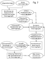
- Fig. 2 shows a schematic block diagram of a more complex regulatory context for controlling the dosing, the part of the drill according to Fig. 1 are.
- FIG. 1 shows a pneumatic seed drill 10 for discharging volume-metered seed, which is guided via a central distributor to individual seed lines with mullions arranged on the muzzle side.
- the seeding machine 10 shown by way of example and schematically has a funnel-shaped storage container 12 for granular material, in particular for seeds, on the underside of which a metering device 14 is located, which meters the granular material or the seed into an air stream 16 generated by a fan 18 and is conveyed in an air line 20, which leads to a vertically arranged riser 22. At a top of the riser 22 - this may be, for example, a so-called. Corrugated pipe o. The like.
- a central manifold 24 which distributes the grain-carrying air stream 26 approximately uniformly to a plurality of seed lines 28.
- the addition of the discharged from the reservoir 12 in the air stream 16 seed or granular good can be done either by the Venturi principle or by supporting the pressurized, located in the closed pressure tank 12 seeds.
- a metering unit 34 located within the seed line 28, typically in the immediate vicinity of the coulter 30, a metering unit 34, which ensures that the coulter 30 is acted upon with granular material or seed, which in approximately the same grain intervals and with substantially the same Delivery speeds in the field soil 32 is delivered. Since in a real seed drill a plurality of such parallel coulters 30 is provided (for example, twenty-four, thirty-two or more), which are each connected to separate seed lines 28 and supplied by these, a corresponding number of metering units according to the invention, each of the same design is provided 34 since each individual seed line 28 has such a metering unit 34.
- the shows Fig. 1 an indicated sensor unit 36, which is arranged in the region of the central distributor 24 and in particular for each seed line 28 by a respective impact sensor o.
- a respective impact sensor o Formed to which the respective part of the air flow 26 with the transported therein seed under contacting largely all in each Partial grain carried grains impinges.
- Particularly suitable as impact sensors of the sensor units 36 are those with piezoelectrically operating sensor surfaces that are sufficiently sensitive to reliably respond to any impact of a seed and to distinguish from contacting lighter particles such as straw or other impurities in the seed, so that very accurate sensor signals are generated can.
- another sensor can be arranged downstream of the metering unit 34, between this and the coulter 30, which detects the grain spacing.
- the metering units 34 arranged in the seed line 28 can in particular have a construction and an operating mode according to the DE 10 2013 215 183 B3 have (see there the Fig. 2 ), the disclosure of which is hereby incorporated by reference.
- the schematic block diagram of Fig. 2 illustrates the structure of a control circuit for linking the sensor signals of the current from the electric drive motors of the metering 34 sensible current signals and the sensor signals of the sensor units 36, which are also linked to other signals to control the metering units 34 in the desired manner.
- the in the Fig. 2 Recognizable control of the drive speeds of the electric drive motors of the metering units 34 takes place for each of these aggregates each seed row of a drill 10, which has a variety of she workout whatsoever.
- the Fig. 2 indicates that base values for a basic setting of the metering units 34 are initially calculated on the basis of the measured travel speed of the seed drill 10 and a desired rate or application rate. From this, values for average drive speeds of the individual metering units 34 are calculated. In addition, the numbers of the grains conveyed in the seed lines 28 to the metering units 34 are detected by means of the sensor units 36. In addition, further grain sensors, which may be arranged between the metering units 34 and the coulters 30, provide for a detection of the grain distances during the delivery of the grains from the metering units 34 and before their deposit in the bottom 32. From these latter three values, a possibly corrected Drive speed calculated for the dosing or calculated a target value for the drive speed. This default value is made available to a control unit for the drive speed control of the metering units, which results in a respective current control value for the drive speed of each individual metering unit 34.
- the operating parameters of the drive motors of the metering units are detected, namely their current voltage values and their current consumption, since these values allow a conclusion on the required torque and thus on the respective degree of filling of the metering.
- These control and measured values are recorded and can be further processed and / or displayed and stored. That is, there is a detection and / or monitoring of the most important or all system parameters that are relevant for the control and operation of dosing. As soon as fixed or variable and possibly dynamically definable limit values for drive parameters or drive speeds of the metering units are exceeded. or undershot, a control intervention can take place, which is reflected in a corrected input speed of the dosing.
Description
Die vorliegende Erfindung betrifft eine Verteilvorrichtung zur Dosierung von körnigem Gut wie Samenkörner, Dünger o. dgl. mit den Merkmalen des unabhängigen Anspruchs 1. Die Erfindung betrifft zudem ein Verfahren zum Ausbringen von granulatartigem Verteilgut, insbesondere von körnigem Saatgut, Dünger o. dgl., mit den Merkmalen des unabhängigen Verfahrensanspruchs 5.The present invention relates to a distribution device for the metering of granular material such as seeds, fertilizer o. The like. With the features of independent claim 1. The invention also relates to a method for applying granular-like material, in particular granular seed, fertilizer o. The like., with the features of the independent method claim 5.
Aus dem Stand der Technik sind verschiedene Ansätze bekannt, die Drillsaat dahingehend zu verbessern, dass die Aussaat gleichmäßiger erfolgt. Das wichtigste Ziel, das hierbei verfolgt wird, besteht darin, die Kornabstände innerhalb der Reihe nicht zu stark variieren zu lassen, um sich damit einer Einzelkornsaat zumindest grob anzunähern.From the prior art, various approaches are known to improve the Drillsaat to the effect that the sowing is more uniform. The most important goal pursued here is not to let the grain distances within the row vary too much in order to at least roughly approximate a single grain seed.
Die
Da es jedoch bei stärkeren Schwankungen im Korntransport unter Umständen zu Verstopfungen im Dosieraggregat kommen kann, da dessen Drehzahlvariation in solchen Situationen zu träge erfolgt, ist es wünschenswert, für die Regelung weitere Parameter zu berücksichtigen. Aus diesem Grund besteht das Ziel der vorliegenden Erfindung darin, die Regelungsgüte und damit die Gleichmäßigkeit der Korndosierung bei einer solchen Vorrichtung, wie sie aus der
Dieses Ziel wird mit dem Gegenstand des unabhängigen Anspruchs 1 dadurch erreicht, dass jedem Dosieraggregat mindestens ein Kornflusssensor vorgeordnet wird, der sich in einer Zuführleitung oder bspw. in einer Verteileinheit wie bspw. einem Verteilerturm befinden kann. Die Daten des Kornflusssensors, der typischerweise durch einen Prallsensor gebildet sein kann, insbesondere durch einen piezoelektrisch arbeitenden Prallsensor, werden regeltechnisch zur Variation der Drehzahl des elektrischen Antriebsmotors des Dosieraggregats verwendet, so dass die Förder- oder Fächerscheibe schneller oder langsamer rotiert, um auf starke Schwankungen im Kornfluss besser reagieren zu können, und um unerwünschte Stauungen oder Verstopfungen aufgrund zu hohen Kornaufkommens zu vermeiden.This object is achieved with the subject matter of independent claim 1, characterized in that each metering unit is preceded by at least one grain flow sensor, which may be located in a supply line or, for example, in a distribution unit such as a distribution tower. The data of the grain flow sensor, which may typically be formed by a baffle sensor, in particular by a piezoelectrically operating impact sensor, are used to control the speed of the electric drive motor of the metering unit, so that the conveyor or fan disc rotates faster or slower to strong fluctuations in the Grain flow to be able to react better, and to avoid unwanted congestion or blockages due to high grain volume.
Wie erwähnt, wird das aktuelle Antriebsmoment des elektrischen Antriebsmotors dadurch bestimmt bzw. hergeleitet, dass dessen elektrische Stromaufnahme gemessen wird, da diese einen unmittelbaren Rückschluss auf die Motorwiderstände und damit auf das aufzuwendende Motormoment zulässt. Das Ziel einer besseren Vergleichmäßigung des ausgebrachten Saatgutes kann durch eine Anpassung der Motordrehzahl auf Grundlage des erfassten Antriebsmoments erreicht werden, wodurch stärkere Schwankungen in der Ausbringmenge eines einzelnen Dosierers in gewünschter Weise ausgeglichen bzw. unterdrückt werden können. Zwar können auf diese Weise die Ausbringmengen zwischen den einzelnen Reihen weiterhin variieren, doch wird das Ziel der optimierten und möglichst nicht schwankenden Kornabstände innerhalb der Reihe erreicht.As mentioned, the current drive torque of the electric drive motor is determined or deduced by the fact that its electrical power consumption is measured, as this allows an immediate conclusion to the engine resistance and thus to the expended engine torque. The aim of better equalization of the seed applied can be achieved by adjusting the engine speed based on the detected drive torque, whereby larger fluctuations in the application rate of a single meter can be compensated or suppressed in the desired manner. Although in this way the application rates between the individual rows can continue to vary, the goal of the optimized and, if possible, unstable grain spacing within the row is not achieved.
Die Versorgung der Dosierer erfolgt über die bereits vorhandene Luftversorgung einer pneumatischen Sämaschine, die typischerweise einen zentralen Verteilerkopf mit flexiblen Saatleitungen zu den einzelnen Säscharen aufweist. Mit diesem Pneumatiksystem werden alle Schare und Dosierer möglichst gleichmäßig mit Saatgut versorgt. Innerhalb dieser flexiblen Saatleitungen sind die einzelnen Dosierer platziert, typischerweise nah an den Säscharen, da die Fallrohre zu den Säscharen normalerweise die Ausgangsleitungen der Dosierer sind.The feeders are supplied via the already existing air supply of a pneumatic seeder, which typically has a central distributor head with flexible seed lines to the individual coulters. With this pneumatic system, all coulters and dosing units are fed as evenly as possible with seed. Within these flexible seed lines, the individual dosers are placed, typically close to the coulters, as the downcomers to the coulters are normally the output lines of the dosers.
Zusätzlich sind in den Fallrohren Kornsensoren zur Überwachung der vom Dosierer abgegebenen Kornmengen angeordnet, so dass diese Sensorwerte zur weiteren Regelung der Antriebsmotoren verwendet werden können.In addition, grain sensors for monitoring the quantities of grain discharged from the meter are arranged in the downpipes, so that these sensor values can be used for further control of the drive motors.
Die beschriebene Dosiervorrichtung eignet sich insbesondere zur Platzierung in kornführenden Leitungen, insbesondere in Saatleitungen einer an sich bekannten Sämaschine, insbesondere einer solchen, die pneumatisch fördert. In jeder Saatleitung kann eine solche Dosiervorrichtung angeordnet sein, wo sie für eine Sicherstellung einer annähernd vereinzelten Saatgutverteilung sorgen kann. Damit handelt es sich bei der Dosiervorrichtung um ein Anbaugerät, das für die Ergänzung einer existierenden Sämaschine geeignet ist und diese zu einer Einzelkornsämaschine macht.The metering device described is particularly suitable for placement in grain-carrying lines, especially in seed lines of a seeder known per se, in particular one that promotes pneumatic. In each seed line such a metering device can be arranged, where it can ensure a nearly isolated seed distribution. Thus, the metering device is an attachment suitable for supplementing an existing seed drill and making it a precision seed drill.
Die Luftströmung trägt und befördert das körnige Gut während seines gesamten Transports vom Kornvorrat bis zur Säschar, wobei die Luftströmung innerhalb des Dosieraggregats in einem ungefähr kreisbogenförmigen Verlauf geführt wird und tangential in eine sich an das Dosieraggregat anschließende und zumindest abschnittsweise leicht gekrümmt verlaufende Ausgangsleitung geleitet wird. Dabei kann vorgesehen sein, dass sich die Kreisbögen der Ausgangsleitung und der Innenmantelfläche des Dosieraggregats tangential berühren und die Luft- und Kornführungsverläufe stufen-/nahtlos ineinander übergehen. Außerdem ist ein Krümmungsradius der Ausgangsleitung zumindest in einem an das Dosieraggregat grenzenden Abschnitt annähernd konstant. Wahlweise kann vorgesehen sein, dass sich der Krümmungsradius der Ausgangsleitung mit steigendem Abstand vom Dosieraggregat stetig oder unstetig öffnet.The air flow carries and conveys the granular material during its entire transport from the grain supply to the coulter, wherein the air flow within the metering unit is guided in an approximately circular arc-shaped course and tangentially into an adjoining the metering and at least partially slightly curved extending outlet line is passed. It can be provided that touch the arcs of the output line and the inner circumferential surface of the dosing tangentially and the air and grain guidance gradients / smoothly merge into each other. In addition, a radius of curvature of the output line is approximately constant at least in a section adjacent to the metering unit. Optionally, it can be provided that the radius of curvature of the output line opens continuously or discontinuously with increasing distance from the metering unit.
Bei einer Sämaschine mit einer Vielzahl derartiger Verteilvorrichtungen, die jeweils mit einem Dosieraggregat und einem vorgeordneten Kornflusssensor ausgestattet sind, werden alle relevanten Daten in einer elektronischen Regelungseinheit verarbeitet, so eine aktuelle Fahrgeschwindigkeit, die Antriebsdrehzahlen der rotierenden Förder- oder Fächerscheiben sowie die Kornflussdaten der Kornflusssensoren in den Zuleitungen zu den Dosieraggregaten. Alle verarbeiteten Daten können vorzugsweise gespeichert, ausgewertet und z.B. für eine Anzeigeeinheit oder für statistische Auswertungen hinsichtlich einer Kornverteilungsgüte o. dgl. verwendet werden.In a seeder with a plurality of such distribution devices, which are each equipped with a metering and an upstream grain flow sensor, all relevant data are processed in an electronic control unit, such as a current travel speed, the drive speeds of the rotating conveyor or fan discs and the grain flow data of the grain flow sensors in the supply lines to the metering units. All processed data may preferably be stored, evaluated and e.g. for a display unit or for statistical evaluations with regard to a grain distribution quality or the like.
Die Regelung der Dosieraggregate kann im Wesentlichen darauf beruhen, dass eine mittlere Umdrehungsgeschwindigkeit für den elektrischen Antriebsmotor der rotierenden Förder- oder Fächerscheibe vorgewählt wird, die in Abhängigkeit von den Messwerten des stromaufwärts angeordneten Kornflusssensors korrigiert bzw. angepasst wird. Zudem kann auf Basis des Messwertverlaufs eine Annäherung an einen idealen Wert für die Antriebsdrehzahl erfolgen, um damit den schwankenden oder in längeren Zeitintervallen sich verändernden Kornmengen besser Rechnung zu tragen.The regulation of the metering units can essentially be based on preselecting an average rotational speed for the electric drive motor of the rotating conveyor or fan disc, which is corrected or adjusted as a function of the measured values of the upstream arranged grain flow sensor. In addition, on the basis of the course of the measured value, an approximation to an ideal value for the drive speed can be made in order better to take into account fluctuating grain quantities or grain quantities that change over longer time intervals.
Die Erfindung schlägt zur Erreichung des oben genannten Ziels weiterhin ein Verfahren zum Ausbringen von granulatartigem Verteilgut, insbesondere von körnigem Saatgut, Dünger o. dgl. vor, das insbesondere mittels einer Verteilvorrichung oder Sämaschine durchgeführt werden kann. Hierbei wird das körnige Gut oder Saatgut mittels einer Dosiereinheit einem Luftvolumenstrom gesteuert zugeteilt und mittels wenigstens einer stromabwärts der Dosiereinheit angeordneten Förderleitung zu wenigstens einer Säschar oder einer anderen bodennah angeordneten oder im Boden geführten Ausbringeinrichtungen für das Saatgut befördert. Das Verfahren sieht vor, dass weitgehend alle im Luftstrom bzw. im jeweiligen Teilstrom getragenen Körner des Saatguts oder Körnerstroms mittels wenigstens einer in einer Zuführleitung zwischen Säschar und Dosiereinheit angeordneten Sensoreinheit erfasst werden, wobei der Luftstrom mit den Körnern zu einem dieser Sensoreinheit nachgeordneten Dosieraggregat gefördert wird, wo die Körner bzw. das Saatgut mittels einer elektromotorisch mit regelbarer Drehzahl angetriebenen rotierenden Förder- oder Fächerscheibe in zumindest abschnittsweise kreisförmigen Bewegungsbahn geführt und/oder umgewälzt werden. Außerdem wird zumindest eine elektrische Stromaufnahme eines elektrischen Antriebsmotors für die innerhalb des Dosieraggregats rotierende Förder- oder Fächerscheibe erfasst, woraus ein wechselndes Drehmoment des elektrischen Antriebsmotors bzw. eine wechselnde oder schwankende Drehmomentanforderung an den elektrischen Antriebsmotor hergeleitet werden. Zudem werden elektrische Sensorsignale der wenigstens einen Sensoreinheit verarbeitet und daraus sowie aus den Stromaufnahmewerten für den elektrischen Antriebsmotor ein Steuersignal für den elektrischen Antriebsmotors des Dosieraggregats zur Erhöhung oder Reduzierung der Antriebsdrehzahl der rotierenden Förder- oder Fächerscheibe generiert.In order to achieve the abovementioned aim, the invention furthermore proposes a method for dispensing granular material, in particular granular seed, fertilizer or the like, which can be carried out in particular by means of a distributor or seed drill. Here, the granular material or seed is allocated by means of a metering unit controlled by an air flow and conveyed by at least one downstream of the metering arranged conveying line to at least one coulter or another ground near or guided in the ground dispensing devices for the seed. The method provides that substantially all carried in the air flow or in the respective partial flow grains of seed or grain flow by means of at least one in a feed line between Coulter and metering unit arranged sensor unit are detected, the air flow is conveyed with the grains to a sensor unit downstream of this dosing unit, where the grains or seed by means of an electric motor driven at variable speed rotating conveyor or fan disc in at least partially circular path of movement and / / or circulated. In addition, at least one electrical current consumption of an electric drive motor for the rotating within the dosing unit conveyor or fan disc is detected, from which an alternating torque of the electric drive motor or an alternating or fluctuating torque request are derived to the electric drive motor. In addition, electrical sensor signals of the at least one sensor unit are processed and generated therefrom and from the current consumption values for the electric drive motor, a control signal for the electric drive motor of the dosing to increase or reduce the drive speed of the rotating conveyor or fan disk.
Das Verfahren kann vorsehen, dass der jeweilige Teil des Luftvolumenstroms mit dem darin beförderten Saatgut oder den darin beförderten Körnern auf die als Prallsensor ausgebildete Sensoreinheit geleitet wird, und dass der jeweilige Teil des Luftvolumenstroms mit dem darin beförderten Saatgut oder den darin beförderten Körnern unter Kontaktierung weitgehend aller im jeweiligen Teilstrom getragenen Körner auf den Prallsensor auftrifft. Außerdem kann vorgesehen sein, dass die Signale der wenigstens einen Sensoreinheit bzw. des wenigstens einen Prallsensors und die Stromverbrauchssignale des elektrischen Antriebsmotors des Dosieraggregats mittels einer elektronischen Regelungseinrichtung verknüpft werden, welche aus diesen Signalen ein variables Drehzahlsteuersignal zur Variation des Durchflusses des Dosieraggregats in Abhängigkeit von einem gemessenen Kornvolumen in der Förderleitung stromaufwärts des Dosieraggregats bildet.The method can provide that the respective part of the air volume flow with the seed transported therein or the grains conveyed therein is directed onto the sensor unit designed as a impact sensor, and that the respective part of the air volume flow with the seed conveyed therein or the grains conveyed therein under contact largely all grains carried in the respective partial flow impinges on the impact sensor. In addition, it can be provided that the signals of the at least one sensor unit or the at least one impact sensor and the power consumption signals of the electric drive motor of the metering unit are linked by means of an electronic control device, which from these signals, a variable speed control signal for varying the flow of the metering unit in response to a measured grain volume in the delivery line upstream of the metering unit forms.
Das vorgeschlagene Regelungsverfahren für die Dosieraggregate einer Sä-, Verteil- oder Ausbringvorrichtung ermöglicht die Abschätzung einer sinnvollen Größenordnung für eine Antriebsdrehzahl und die Vorwahl einer mittleren Umdrehungsgeschwindigkeit für den elektrischen Antriebsmotor der rotierenden Förder- oder Fächerscheibe. Gleichzeitig kann diese mittlere Drehzahl auf Grundlage von den Messwerten des stromaufwärts angeordneten Kornflusssensors ständig korrigiert bzw. angepasst werden. Zudem kann auf Basis des Messwertverlaufs eine Annäherung an einen idealen Wert für die Antriebsdrehzahl erfolgen, um damit den schwankenden oder in längeren Zeitintervallen sich verändernden Kornmengen besser Rechnung tragen zu können, so dass insgesamt eine optimierte Annäherung an eine Einzelkornsaat ermöglicht ist.The proposed control method for the dosing of a sowing, distribution or dispensing device allows the estimation of a meaningful order of magnitude for a drive speed and the preselection of a mean rotational speed for the electric drive motor of the rotating conveyor or fan disc. At the same time, this average rotational speed can be constantly corrected or adjusted on the basis of the measured values of the upstream grain flow sensor. In addition, on the basis of the course of the measured value, an approximation to an ideal value for the drive speed can be made in order better to take into account the fluctuating amounts of grain or changes in longer time intervals so that overall an optimized approach to a single-grain seed is possible.
Im Folgenden sollen Ausführungsbeispiele die Erfindung und ihre Vorteile anhand der beigefügten Figuren näher erläutern. Die Größenverhältnisse der einzelnen Elemente zueinander in den Figuren entsprechen nicht immer den realen Größenverhältnissen, da einige Formen vereinfacht und andere Formen zur besseren Veranschaulichung vergrößert im Verhältnis zu anderen Elementen dargestellt sind.In the following, embodiments of the invention and their advantages with reference to the accompanying figures will be explained in more detail. The proportions of the individual elements to one another in the figures do not always correspond to the actual size ratios, since some shapes are simplified and other shapes are shown enlarged in relation to other elements for better illustration.
Für gleiche oder gleich wirkende Elemente der Erfindung werden identische Bezugszeichen verwendet. Ferner werden der Übersicht halber nur Bezugszeichen in den einzelnen Figuren dargestellt, die für die Beschreibung der jeweiligen Figur erforderlich sind. Die dargestellten Ausführungsformen stellen lediglich Beispiele dar, wie die erfindungsgemäße Vorrichtung ausgestaltet sein kann und stellen keine abschließende Begrenzung dar.For identical or equivalent elements of the invention, identical reference numerals are used. Furthermore, for the sake of clarity, only reference symbols are shown in the individual figures, which are required for the description of the respective figure. The illustrated embodiments are only examples of how the device according to the invention can be designed and do not represent a final limitation.
Die schematische Darstellung der
Wie es die
Weiterhin zeigt die
Für die exakte Regelung des Dosieraggregats 34 und der von diesem zur Säschar 30 beförderten Saatmenge sowie für die Einhaltung der gewünschten Kornabstände bei der Ausbringung des Saatguts ist es wichtig, dass in den Saatleitungen 28 die Sensoreinheiten 36 jeweils stromaufwärts angeordnet sind und dass diesen Sensoreinheiten 36 die Dosieraggregate 34 jeweils nachgeordnet sind. Auf diese Weise kann eine Regelung gemäß
Weiterhin kann optional ein weiterer Sensor stromabwärts des Dosieraggregats 34, zwischen diesem und dem Säschar 30 angeordnet sein, der den Kornabstand erfasst.Furthermore, optionally another sensor can be arranged downstream of the metering unit 34, between this and the
Die in der Saatleitung 28 angeordneten Dosieraggregate 34 können insbesondere einen Aufbau und eine Funktionsweise gemäß der
Das schematische Blockschaltbild der
Die
Darüber hinaus werden die Betriebsparameter der Antriebsmotoren der Dosieraggregate erfasst, nämlich deren aktuelle Spannungswerte und deren Stromaufnahme, da diese Werte einen Rückschluss auf das benötigte Drehmoment und damit auf den jeweiligen Füllgrad des Dosieraggregats erlauben. Diese Steuer- und Messwerte werden erfasst und können weiterverarbeitet und/oder angezeigt sowie gespeichert werden. D.h., es erfolgt eine Erfassung und/oder ein Monitoring der wichtigsten oder aller Systemparameter, die für die Steuerung und den Betrieb der Dosieraggregate relevant sind. Sobald feste oder variable und ggf. dynamisch vorgebbare Grenzwerte für Antriebsparameter bzw. Antriebsdrehzahlen der Dosieraggregate über- oder unterschritten werden, kann ein Regeleingriff erfolgen, was sich in einer korrigierten Antriebsdrehzahl der Dosieraggregate niederschlägt.In addition, the operating parameters of the drive motors of the metering units are detected, namely their current voltage values and their current consumption, since these values allow a conclusion on the required torque and thus on the respective degree of filling of the metering. These control and measured values are recorded and can be further processed and / or displayed and stored. That is, there is a detection and / or monitoring of the most important or all system parameters that are relevant for the control and operation of dosing. As soon as fixed or variable and possibly dynamically definable limit values for drive parameters or drive speeds of the metering units are exceeded. or undershot, a control intervention can take place, which is reflected in a corrected input speed of the dosing.
Alle diese erwähnten Schritte werden typischerweise zyklisch durchlaufen, wodurch sich eine präzise Regelung der Säaggregate ergibt.All these mentioned steps are typically cycled, resulting in a precise control of the sowing units.
Die Erfindung wurde unter Bezugnahme auf eine bevorzugte Ausführungsform beschrieben. Es ist jedoch für einen Fachmann vorstellbar, dass Abwandlungen oder Änderungen der Erfindung gemacht werden können, ohne dabei den Schutzbereich der nachstehenden Ansprüche zu verlassen.The invention has been described with reference to a preferred embodiment. However, it will be apparent to those skilled in the art that modifications or changes may be made to the invention without departing from the scope of the following claims.
- 1010
- Sämaschineseeder
- 1212
- Vorratsbehälterreservoir
- 1414
- Dosiereinrichtungmetering
- 1616
- Luftstromairflow
- 1818
- Gebläsefan
- 2020
- Luftleitungair line
- 2222
- Steigrohr (Wellrohr)Riser (corrugated tube)
- 2424
- Zentralverteiler, zentraler VerteilerCentral distributor, central distributor
- 2626
- körnertragender Luftstrom, körnertragende Luftströmunggranular airflow, granular airflow
- 2828
- Saatleitungseed tube
- 3030
- Säscharcoulter
- 3232
- Boden, AckerbodenSoil, farmland
- 3434
- Dosieraggregatmetering unit
- 3636
- Sensoreinheitsensor unit
Claims (7)
- Distribution device for distributing material of a granular nature, in particular for granular seeds, fertilizer, or the like, in particular a sowing machine (10),- with an air conveyor unit (18) for generating an air volume flow (16) and at least one metering unit (14) arranged downstream of the air conveyor unit for the controllable allocation of the granular material to the air volume flow (16),- and with at least one conveyor line (20, 22), which is arranged downstream of the metering unit (14) and which is provided at the end with at least one seed drill coulter (30) or with another sowing device for the granular material or the grains arranged near ground level or being guided in the soil,characterized in that in the least one conveyor line (20, 22) at least one sensor unit (36) is arranged, for detecting largely all grains from among the granular material being carried in the air stream (26) and/or in the respective partial flow, and passing this sensor unit (36),
and with a metering device (34) arranged downstream of this sensor unit (36), which metering device (34) is equipped with a conveyor disk or fan disk, which is electromotively settable in rotation at a regulatable rotational speed, for the circular movement and/or circulation of the granular material or the grains, at least in sections, wherein an electronic regulating device processes at least the electric current consumption of the electric drive motor for the conveyor disk or fan disk rotating within the metering device (34) for deriving a changing torque of the electric drive motor and/or a changing or fluctuating torque request on the electric drive motor as well as the electric sensor signals of the at least one sensor unit (36), and generates a control signal thereof for the electric drive motor of the metering device (34) for the increase or reduction of the drive speed of the rotating conveyor disk or fan disk. - Distribution device as recited in claim 1, in which the at least one sensor unit (36) comprises an impact sensor, which is impacted by the respective part of the air volume flow (26) with the grains being conveyed therein, with largely all of the grains that are being carried in the respective partial flow making contact.
- Distribution device as recited in claim 2, in which the electronic regulating device links the signals of the at least one sensor unit (36) and/or of the at least one impact sensor with the power consumption signals of the electric drive motor of the metering device (34), in order to form a variable speed control signal thereof for varying the flow rate of the metering device (34) in dependence on a measured grain quantity in the conveyor line upstream of the metering device (34).
- Sowing or spreading machine (10) for granular material or granular seeds with a plurality of rows or seed rows located next to each other, each with a distribution device as recited in one of claims 1 to 3, each of which is allocated a seed drill coulter (30) or a similar sowing device for placing the grains or granular seeds into the soil (32) at a definable placement depth, which sowing devices and/or seed drill coulters (30) are supplied with grains from at least one grain storage hopper (12) via respectively separate feed tubes (28), wherein a sensor unit (36) is allocated to each of these feed tubes (28) for detecting the grains located in the partial flow, wherein each of these sowing devices and/or seed drill coulters (30) is respectively equipped with a metering device (34) for granular material, and wherein each sensor unit (36) and each metering device (34) is respectively connected in signaling terms with a central regulating device, which processes the quantities of grains detected in the feed tubes (28) as well as the motor torques measured in the metering devices (34), and which regulates the grain spacing for each metering device (34) by varying the drive speeds of the drives under consideration of target values for the grain spacing and/or of target values of a longitudinal distribution of the grains from single, multiple, or all metering devices (34).
- Method for spreading material of granular nature, in particular of granular seeds, fertilizer, or the like, in particular by means of a distribution device or sowing machine (10), wherein the granular material or the seeds are controllably allocated to an air volume flow (16) by means of a metering unit (14), and is conveyed with at least one conveyor line (20, 22), which is arranged downstream of the metering unit (14), to at least one seed drill coulter (30) or to another sowing device for the granular material arranged near ground level or being guided in the soil, characterized in that largely all grains of the granular material or grain flow carried within the air stream (26) and/or in the respective partial flow are detected by means of at least a sensor unit (36) arranged in a feed tube (28) between the seed drill coulter (30) and the metering unit (14),
wherein the air stream is conveyed with the grains to the metering device (34) arranged downstream of the sensor unit (36), where the grains and/or the granular material are guided and/or circulated in a movement which is circular at least in sections, with a conveyor disk or fan disk, which is electromotively settable in rotation at a regulatable rotational speed,
wherein at least the electric current consumption of the electric drive motor for the conveyor disk or fan disk rotating within the metering device (34) is detected and a changing torque of the electric drive motor and/or a changing or fluctuating torque request on the electric drive motor is derived thereof,
and wherein electric sensor signals of the at least one sensor unit (36) are generated, and a control signal for the electric drive motor of the metering device (34) for the increase or reduction of the drive speed of the rotating conveyor disk or fan disk is generated thereof as well as from the electric current consumption values of the drive motor. - Method as recited in claim 5, in which the respective part of the air volume flow (26) with the granular material conveyed therein or the grains conveyed therein is guided to the sensor unit (36) which is formed as an impact sensor, which is impacted by the respective part of the air volume flow (26) with the granular material being conveyed therein or the grains being conveyed therein, with largely all of the grains that are being carried in the respective partial flow making contact.
- Method as recited in claim 5 or 6, in which the signals of the at least one sensor unit (36) and/or of the at least one impact sensor and the power consumption signals of the electric drive motor of the metering device (34) are linked by an electronic regulating device, in order to form a variable speed control signal thereof for varying the flow rate of the metering device (34) in dependence on a measured grain quantity in the conveyor line upstream of the metering device (34).
Applications Claiming Priority (1)
| Application Number | Priority Date | Filing Date | Title |
|---|---|---|---|
| DE102014114028.1A DE102014114028A1 (en) | 2014-09-26 | 2014-09-26 | Distributor for granular material |
Publications (2)
| Publication Number | Publication Date |
|---|---|
| EP3000299A1 EP3000299A1 (en) | 2016-03-30 |
| EP3000299B1 true EP3000299B1 (en) | 2017-02-22 |
Family
ID=53969264
Family Applications (1)
| Application Number | Title | Priority Date | Filing Date |
|---|---|---|---|
| EP15182126.1A Active EP3000299B1 (en) | 2014-09-26 | 2015-08-24 | Distribution device for granular materials |
Country Status (3)
| Country | Link |
|---|---|
| US (1) | US9894830B2 (en) |
| EP (1) | EP3000299B1 (en) |
| DE (1) | DE102014114028A1 (en) |
Families Citing this family (27)
| Publication number | Priority date | Publication date | Assignee | Title |
|---|---|---|---|---|
| US9615506B2 (en) * | 2014-11-10 | 2017-04-11 | Cnh Industrial Canada, Ltd. | System for monitoring and controlling product distribution in an agricultural system |
| US10492359B2 (en) | 2015-09-30 | 2019-12-03 | Deere & Company | Seeding system |
| US9814173B2 (en) * | 2015-09-30 | 2017-11-14 | Deere & Company | Seeding system |
| US9949427B2 (en) | 2015-09-30 | 2018-04-24 | Deere & Company | System and method of distributing seeds and agricultural particles |
| US20170086351A1 (en) | 2015-09-30 | 2017-03-30 | Deere & Company | Seed metering system and method of operating the same |
| DE102015121600A1 (en) | 2015-12-11 | 2017-06-14 | Horsch Maschinen Gmbh | Method and device for discharging granular material |
| FR3050607B1 (en) * | 2016-04-28 | 2018-11-30 | Sulky Burel | SEEDER EQUIPPED WITH A DEVICE FOR REGULATING THE DISTRIBUTION OF SEEDS, AND CORRESPONDING REGULATION DEVICE |
| CA2977467A1 (en) | 2016-10-11 | 2018-04-11 | Deere & Company | Seeding system |
| DE102017103640A1 (en) | 2017-02-22 | 2018-08-23 | Horsch Maschinen Gmbh | Method and control system for an agricultural distribution machine for dosing and discharging granular material |
| CN109673216A (en) * | 2017-10-21 | 2019-04-26 | 灵璧迪五机械制造有限公司 | A kind of simple type seeding plough |
| US10942053B2 (en) | 2018-05-14 | 2021-03-09 | Deere & Company | Seeding system |
| CN109463078A (en) * | 2018-11-20 | 2019-03-15 | 南县伟业机械制造有限公司 | A kind of quantitative material storing box and the rape seeding machine using the material storing box |
| DE102019128037A1 (en) * | 2019-10-17 | 2021-04-22 | Amazonen-Werke H. Dreyer Gmbh & Co. Kg | Method for operating a portioning device |
| CN110839373A (en) * | 2019-12-04 | 2020-02-28 | 王伟 | Intelligent device based on it is rotatory to accomplish quantitative seeding and shovel soil integration |
| US11564344B2 (en) | 2019-12-24 | 2023-01-31 | Cnh Industrial America Llc | Particle delivery system of an agricultural row unit |
| US11523555B2 (en) | 2019-12-24 | 2022-12-13 | Cnh Industrial America Llc | Particle delivery system of an agricultural row unit |
| US11553639B2 (en) | 2019-12-24 | 2023-01-17 | Cnh Industrial America Llc | Particle delivery system of an agricultural row unit |
| US11523556B2 (en) | 2019-12-24 | 2022-12-13 | Cnh Industrial America Llc | Particle delivery system of an agricultural row unit |
| US11483963B2 (en) | 2019-12-24 | 2022-11-01 | Cnh Industrial America Llc | Particle delivery system of an agricultural row unit |
| US11490558B2 (en) | 2019-12-24 | 2022-11-08 | Cnh Industrial America Llc | Particle delivery system of an agricultural row unit |
| US11553638B2 (en) | 2019-12-24 | 2023-01-17 | Cnh Industrial America Llc | Particle delivery system of an agricultural row unit |
| US11516958B2 (en) | 2019-12-24 | 2022-12-06 | Cnh Industrial America Llc | Particle delivery system of an agricultural row unit |
| US11589500B2 (en) | 2019-12-24 | 2023-02-28 | Cnh Industrial America Llc | Particle delivery system of an agricultural row unit |
| US11596095B2 (en) | 2019-12-24 | 2023-03-07 | Cnh Industrial America Llc | Particle delivery system of an agricultural row unit |
| US11564346B2 (en) | 2019-12-24 | 2023-01-31 | Cnh Industrial America Llc | Particle delivery system of an agricultural row unit |
| US11582899B2 (en) | 2019-12-24 | 2023-02-21 | Cnh Industrial America Llc | Particle delivery system of an agricultural row unit |
| DE102020120561A1 (en) | 2020-08-04 | 2022-02-10 | Horsch Maschinen Gmbh | Agricultural distribution device, preferably distribution tower |
Family Cites Families (6)
| Publication number | Priority date | Publication date | Assignee | Title |
|---|---|---|---|---|
| DE3625114A1 (en) * | 1986-07-25 | 1988-02-04 | Amazonen Werke Dreyer H | AGRICULTURAL DISTRIBUTION MACHINE |
| DE58906477D1 (en) * | 1988-07-15 | 1994-02-03 | Amazonen Werke Dreyer H | Process for sowing seeds. |
| DE4434248A1 (en) * | 1994-09-24 | 1996-03-28 | Amazonen Werke Dreyer H | Pneumatic distributor |
| DE102006038865A1 (en) * | 2006-08-18 | 2008-02-21 | Alois Pöttinger Maschinenfabrik Gmbh | Sowing machine and method for controlling the discharge of a drill |
| US8950260B2 (en) * | 2011-03-11 | 2015-02-10 | Intelligent Agricultural Solutions, Llc | Air seeder monitoring and equalization system using acoustic sensors |
| DE102013215183B3 (en) | 2013-08-01 | 2014-09-11 | Horsch Maschinen Gmbh | Process for dosing granular material and granular dosing device |
-
2014
- 2014-09-26 DE DE102014114028.1A patent/DE102014114028A1/en not_active Withdrawn
-
2015
- 2015-08-24 EP EP15182126.1A patent/EP3000299B1/en active Active
- 2015-09-25 US US14/865,243 patent/US9894830B2/en active Active
Also Published As
| Publication number | Publication date |
|---|---|
| US9894830B2 (en) | 2018-02-20 |
| DE102014114028A1 (en) | 2016-03-31 |
| EP3000299A1 (en) | 2016-03-30 |
| US20160088791A1 (en) | 2016-03-31 |
Similar Documents
| Publication | Publication Date | Title |
|---|---|---|
| EP3000299B1 (en) | Distribution device for granular materials | |
| EP2988586B1 (en) | Method for dosing granular material and dosing device for granular material | |
| EP2932818B1 (en) | Distribution device and method for delivery of granular goods | |
| EP3127415B1 (en) | Method for dosing granular goods, and control system for a dosing unit of a distributing and/or sowing device | |
| EP3777500B1 (en) | Method for applying granular material | |
| EP3501250B1 (en) | Agricultural distributor and method for individual row and group control of such an agricultural distributor | |
| EP3026998B1 (en) | Method for dosing granular material and dosing device for granular material | |
| DE102015121600A1 (en) | Method and device for discharging granular material | |
| EP3366098A1 (en) | Method and control system for an agricultural distribution machine for dosing and dispensing of granulate distributed goods | |
| EP2853141A1 (en) | Sowing machine | |
| DE102015114156A1 (en) | Sowing machine and method for operating a seed drill | |
| DE102006038865A1 (en) | Sowing machine and method for controlling the discharge of a drill | |
| EP3662734B1 (en) | Control and / or regulating system for an agricultural distribution machine, agricultural distribution machine and method for controlling and/ or regulating an agricultural distribution machine | |
| EP3662735B1 (en) | Distribution machine for spreading granular agricultural spreading material and method for distributing granular agricultural spreading material | |
| EP2342966A1 (en) | Combined seed and fertilizer dispensing device | |
| EP0350634A2 (en) | Method for depositing grain seeds | |
| EP4090149B1 (en) | Spreading machine | |
| DE102004025758A1 (en) | Commodity e.g. seed, distribution machine e.g. seeder, for use with tractor, has electronic controller to automatically adjust rotational speed of hydraulic motor of blower through hydraulic valve based on type and quantity of commodity | |
| DE102018130717A1 (en) | Agricultural spreading machine and method for spreading granular spreading material | |
| EP0654207B1 (en) | Pneumatic broadcaster | |
| DE102015210212A1 (en) | Method and device for discharging granular material | |
| DE102022121240A1 (en) | Material distribution system for an application machine, application machine and method for distributing application material | |
| DE202018006583U1 (en) | Agricultural spreading machine for spreading granular material | |
| DE102021104407A1 (en) | AGRICULTURAL SPREADING MACHINE AND METHOD OF OPERATING SUCH AGRICULTURAL SPREADING MACHINE | |
| DE102020133357A1 (en) | Dosing system of an agricultural seeder |
Legal Events
| Date | Code | Title | Description |
|---|---|---|---|
| PUAI | Public reference made under article 153(3) epc to a published international application that has entered the european phase |
Free format text: ORIGINAL CODE: 0009012 |
|
| AK | Designated contracting states |
Kind code of ref document: A1 Designated state(s): AL AT BE BG CH CY CZ DE DK EE ES FI FR GB GR HR HU IE IS IT LI LT LU LV MC MK MT NL NO PL PT RO RS SE SI SK SM TR |
|
| AX | Request for extension of the european patent |
Extension state: BA ME |
|
| 17P | Request for examination filed |
Effective date: 20160307 |
|
| RBV | Designated contracting states (corrected) |
Designated state(s): AL AT BE BG CH CY CZ DE DK EE ES FI FR GB GR HR HU IE IS IT LI LT LU LV MC MK MT NL NO PL PT RO RS SE SI SK SM TR |
|
| GRAP | Despatch of communication of intention to grant a patent |
Free format text: ORIGINAL CODE: EPIDOSNIGR1 |
|
| RIC1 | Information provided on ipc code assigned before grant |
Ipc: A01C 7/08 20060101ALN20160630BHEP Ipc: A01C 7/04 20060101ALN20160630BHEP Ipc: A01C 7/16 20060101ALN20160630BHEP Ipc: A01C 7/10 20060101AFI20160630BHEP Ipc: A01C 5/06 20060101ALI20160630BHEP |
|
| RIC1 | Information provided on ipc code assigned before grant |
Ipc: A01C 7/16 20060101ALN20160714BHEP Ipc: A01C 5/06 20060101ALI20160714BHEP Ipc: A01C 7/08 20060101ALN20160714BHEP Ipc: A01C 7/04 20060101ALN20160714BHEP Ipc: A01C 7/10 20060101AFI20160714BHEP |
|
| INTG | Intention to grant announced |
Effective date: 20160727 |
|
| GRAS | Grant fee paid |
Free format text: ORIGINAL CODE: EPIDOSNIGR3 |
|
| GRAJ | Information related to disapproval of communication of intention to grant by the applicant or resumption of examination proceedings by the epo deleted |
Free format text: ORIGINAL CODE: EPIDOSDIGR1 |
|
| GRAL | Information related to payment of fee for publishing/printing deleted |
Free format text: ORIGINAL CODE: EPIDOSDIGR3 |
|
| INTC | Intention to grant announced (deleted) | ||
| GRAR | Information related to intention to grant a patent recorded |
Free format text: ORIGINAL CODE: EPIDOSNIGR71 |
|
| RIC1 | Information provided on ipc code assigned before grant |
Ipc: A01C 5/06 20060101ALI20161205BHEP Ipc: A01C 7/16 20060101ALN20161205BHEP Ipc: A01C 7/04 20060101ALN20161205BHEP Ipc: A01C 7/08 20060101ALN20161205BHEP Ipc: A01C 7/10 20060101AFI20161205BHEP |
|
| GRAA | (expected) grant |
Free format text: ORIGINAL CODE: 0009210 |
|
| INTG | Intention to grant announced |
Effective date: 20170111 |
|
| AK | Designated contracting states |
Kind code of ref document: B1 Designated state(s): AL AT BE BG CH CY CZ DE DK EE ES FI FR GB GR HR HU IE IS IT LI LT LU LV MC MK MT NL NO PL PT RO RS SE SI SK SM TR |
|
| REG | Reference to a national code |
Ref country code: GB Ref legal event code: FG4D Free format text: NOT ENGLISH |
|
| REG | Reference to a national code |
Ref country code: CH Ref legal event code: EP |
|
| REG | Reference to a national code |
Ref country code: AT Ref legal event code: REF Ref document number: 868552 Country of ref document: AT Kind code of ref document: T Effective date: 20170315 |
|
| REG | Reference to a national code |
Ref country code: IE Ref legal event code: FG4D Free format text: LANGUAGE OF EP DOCUMENT: GERMAN |
|
| REG | Reference to a national code |
Ref country code: DE Ref legal event code: R096 Ref document number: 502015000599 Country of ref document: DE |
|
| REG | Reference to a national code |
Ref country code: LT Ref legal event code: MG4D |
|
| REG | Reference to a national code |
Ref country code: NL Ref legal event code: MP Effective date: 20170222 |
|
| PG25 | Lapsed in a contracting state [announced via postgrant information from national office to epo] |
Ref country code: HR Free format text: LAPSE BECAUSE OF FAILURE TO SUBMIT A TRANSLATION OF THE DESCRIPTION OR TO PAY THE FEE WITHIN THE PRESCRIBED TIME-LIMIT Effective date: 20170222 Ref country code: LT Free format text: LAPSE BECAUSE OF FAILURE TO SUBMIT A TRANSLATION OF THE DESCRIPTION OR TO PAY THE FEE WITHIN THE PRESCRIBED TIME-LIMIT Effective date: 20170222 Ref country code: GR Free format text: LAPSE BECAUSE OF FAILURE TO SUBMIT A TRANSLATION OF THE DESCRIPTION OR TO PAY THE FEE WITHIN THE PRESCRIBED TIME-LIMIT Effective date: 20170523 Ref country code: NO Free format text: LAPSE BECAUSE OF FAILURE TO SUBMIT A TRANSLATION OF THE DESCRIPTION OR TO PAY THE FEE WITHIN THE PRESCRIBED TIME-LIMIT Effective date: 20170522 Ref country code: FI Free format text: LAPSE BECAUSE OF FAILURE TO SUBMIT A TRANSLATION OF THE DESCRIPTION OR TO PAY THE FEE WITHIN THE PRESCRIBED TIME-LIMIT Effective date: 20170222 |
|
| REG | Reference to a national code |
Ref country code: FR Ref legal event code: PLFP Year of fee payment: 3 |
|
| PG25 | Lapsed in a contracting state [announced via postgrant information from national office to epo] |
Ref country code: ES Free format text: LAPSE BECAUSE OF FAILURE TO SUBMIT A TRANSLATION OF THE DESCRIPTION OR TO PAY THE FEE WITHIN THE PRESCRIBED TIME-LIMIT Effective date: 20170222 Ref country code: SE Free format text: LAPSE BECAUSE OF FAILURE TO SUBMIT A TRANSLATION OF THE DESCRIPTION OR TO PAY THE FEE WITHIN THE PRESCRIBED TIME-LIMIT Effective date: 20170222 Ref country code: LV Free format text: LAPSE BECAUSE OF FAILURE TO SUBMIT A TRANSLATION OF THE DESCRIPTION OR TO PAY THE FEE WITHIN THE PRESCRIBED TIME-LIMIT Effective date: 20170222 Ref country code: PT Free format text: LAPSE BECAUSE OF FAILURE TO SUBMIT A TRANSLATION OF THE DESCRIPTION OR TO PAY THE FEE WITHIN THE PRESCRIBED TIME-LIMIT Effective date: 20170622 Ref country code: BG Free format text: LAPSE BECAUSE OF FAILURE TO SUBMIT A TRANSLATION OF THE DESCRIPTION OR TO PAY THE FEE WITHIN THE PRESCRIBED TIME-LIMIT Effective date: 20170522 Ref country code: RS Free format text: LAPSE BECAUSE OF FAILURE TO SUBMIT A TRANSLATION OF THE DESCRIPTION OR TO PAY THE FEE WITHIN THE PRESCRIBED TIME-LIMIT Effective date: 20170222 Ref country code: NL Free format text: LAPSE BECAUSE OF NON-PAYMENT OF DUE FEES Effective date: 20170222 |
|
| PG25 | Lapsed in a contracting state [announced via postgrant information from national office to epo] |
Ref country code: SK Free format text: LAPSE BECAUSE OF FAILURE TO SUBMIT A TRANSLATION OF THE DESCRIPTION OR TO PAY THE FEE WITHIN THE PRESCRIBED TIME-LIMIT Effective date: 20170222 Ref country code: EE Free format text: LAPSE BECAUSE OF FAILURE TO SUBMIT A TRANSLATION OF THE DESCRIPTION OR TO PAY THE FEE WITHIN THE PRESCRIBED TIME-LIMIT Effective date: 20170222 Ref country code: CZ Free format text: LAPSE BECAUSE OF FAILURE TO SUBMIT A TRANSLATION OF THE DESCRIPTION OR TO PAY THE FEE WITHIN THE PRESCRIBED TIME-LIMIT Effective date: 20170222 Ref country code: RO Free format text: LAPSE BECAUSE OF FAILURE TO SUBMIT A TRANSLATION OF THE DESCRIPTION OR TO PAY THE FEE WITHIN THE PRESCRIBED TIME-LIMIT Effective date: 20170222 Ref country code: IT Free format text: LAPSE BECAUSE OF FAILURE TO SUBMIT A TRANSLATION OF THE DESCRIPTION OR TO PAY THE FEE WITHIN THE PRESCRIBED TIME-LIMIT Effective date: 20170222 |
|
| REG | Reference to a national code |
Ref country code: DE Ref legal event code: R097 Ref document number: 502015000599 Country of ref document: DE |
|
| PG25 | Lapsed in a contracting state [announced via postgrant information from national office to epo] |
Ref country code: SM Free format text: LAPSE BECAUSE OF FAILURE TO SUBMIT A TRANSLATION OF THE DESCRIPTION OR TO PAY THE FEE WITHIN THE PRESCRIBED TIME-LIMIT Effective date: 20170222 Ref country code: DK Free format text: LAPSE BECAUSE OF FAILURE TO SUBMIT A TRANSLATION OF THE DESCRIPTION OR TO PAY THE FEE WITHIN THE PRESCRIBED TIME-LIMIT Effective date: 20170222 Ref country code: PL Free format text: LAPSE BECAUSE OF FAILURE TO SUBMIT A TRANSLATION OF THE DESCRIPTION OR TO PAY THE FEE WITHIN THE PRESCRIBED TIME-LIMIT Effective date: 20170222 |
|
| PLBE | No opposition filed within time limit |
Free format text: ORIGINAL CODE: 0009261 |
|
| STAA | Information on the status of an ep patent application or granted ep patent |
Free format text: STATUS: NO OPPOSITION FILED WITHIN TIME LIMIT |
|
| 26N | No opposition filed |
Effective date: 20171123 |
|
| PG25 | Lapsed in a contracting state [announced via postgrant information from national office to epo] |
Ref country code: SI Free format text: LAPSE BECAUSE OF FAILURE TO SUBMIT A TRANSLATION OF THE DESCRIPTION OR TO PAY THE FEE WITHIN THE PRESCRIBED TIME-LIMIT Effective date: 20170222 |
|
| PG25 | Lapsed in a contracting state [announced via postgrant information from national office to epo] |
Ref country code: MC Free format text: LAPSE BECAUSE OF FAILURE TO SUBMIT A TRANSLATION OF THE DESCRIPTION OR TO PAY THE FEE WITHIN THE PRESCRIBED TIME-LIMIT Effective date: 20170222 |
|
| REG | Reference to a national code |
Ref country code: BE Ref legal event code: MM Effective date: 20170831 |
|
| REG | Reference to a national code |
Ref country code: IE Ref legal event code: MM4A |
|
| PG25 | Lapsed in a contracting state [announced via postgrant information from national office to epo] |
Ref country code: LU Free format text: LAPSE BECAUSE OF NON-PAYMENT OF DUE FEES Effective date: 20170824 |
|
| PG25 | Lapsed in a contracting state [announced via postgrant information from national office to epo] |
Ref country code: IE Free format text: LAPSE BECAUSE OF NON-PAYMENT OF DUE FEES Effective date: 20170824 |
|
| REG | Reference to a national code |
Ref country code: FR Ref legal event code: PLFP Year of fee payment: 4 |
|
| PG25 | Lapsed in a contracting state [announced via postgrant information from national office to epo] |
Ref country code: BE Free format text: LAPSE BECAUSE OF NON-PAYMENT OF DUE FEES Effective date: 20170831 |
|
| PG25 | Lapsed in a contracting state [announced via postgrant information from national office to epo] |
Ref country code: MT Free format text: LAPSE BECAUSE OF FAILURE TO SUBMIT A TRANSLATION OF THE DESCRIPTION OR TO PAY THE FEE WITHIN THE PRESCRIBED TIME-LIMIT Effective date: 20170222 |
|
| REG | Reference to a national code |
Ref country code: CH Ref legal event code: PL |
|
| PG25 | Lapsed in a contracting state [announced via postgrant information from national office to epo] |
Ref country code: CH Free format text: LAPSE BECAUSE OF NON-PAYMENT OF DUE FEES Effective date: 20180831 Ref country code: LI Free format text: LAPSE BECAUSE OF NON-PAYMENT OF DUE FEES Effective date: 20180831 |
|
| PG25 | Lapsed in a contracting state [announced via postgrant information from national office to epo] |
Ref country code: HU Free format text: LAPSE BECAUSE OF FAILURE TO SUBMIT A TRANSLATION OF THE DESCRIPTION OR TO PAY THE FEE WITHIN THE PRESCRIBED TIME-LIMIT; INVALID AB INITIO Effective date: 20150824 |
|
| PG25 | Lapsed in a contracting state [announced via postgrant information from national office to epo] |
Ref country code: CY Free format text: LAPSE BECAUSE OF FAILURE TO SUBMIT A TRANSLATION OF THE DESCRIPTION OR TO PAY THE FEE WITHIN THE PRESCRIBED TIME-LIMIT Effective date: 20170222 |
|
| PG25 | Lapsed in a contracting state [announced via postgrant information from national office to epo] |
Ref country code: MK Free format text: LAPSE BECAUSE OF FAILURE TO SUBMIT A TRANSLATION OF THE DESCRIPTION OR TO PAY THE FEE WITHIN THE PRESCRIBED TIME-LIMIT Effective date: 20170222 |
|
| PG25 | Lapsed in a contracting state [announced via postgrant information from national office to epo] |
Ref country code: TR Free format text: LAPSE BECAUSE OF FAILURE TO SUBMIT A TRANSLATION OF THE DESCRIPTION OR TO PAY THE FEE WITHIN THE PRESCRIBED TIME-LIMIT Effective date: 20170222 |
|
| GBPC | Gb: european patent ceased through non-payment of renewal fee |
Effective date: 20190824 |
|
| PG25 | Lapsed in a contracting state [announced via postgrant information from national office to epo] |
Ref country code: AL Free format text: LAPSE BECAUSE OF FAILURE TO SUBMIT A TRANSLATION OF THE DESCRIPTION OR TO PAY THE FEE WITHIN THE PRESCRIBED TIME-LIMIT Effective date: 20170222 Ref country code: IS Free format text: LAPSE BECAUSE OF FAILURE TO SUBMIT A TRANSLATION OF THE DESCRIPTION OR TO PAY THE FEE WITHIN THE PRESCRIBED TIME-LIMIT Effective date: 20170622 |
|
| PG25 | Lapsed in a contracting state [announced via postgrant information from national office to epo] |
Ref country code: GB Free format text: LAPSE BECAUSE OF NON-PAYMENT OF DUE FEES Effective date: 20190824 |
|
| REG | Reference to a national code |
Ref country code: AT Ref legal event code: MM01 Ref document number: 868552 Country of ref document: AT Kind code of ref document: T Effective date: 20200824 |
|
| PG25 | Lapsed in a contracting state [announced via postgrant information from national office to epo] |
Ref country code: AT Free format text: LAPSE BECAUSE OF NON-PAYMENT OF DUE FEES Effective date: 20200824 |
|
| PGFP | Annual fee paid to national office [announced via postgrant information from national office to epo] |
Ref country code: FR Payment date: 20230822 Year of fee payment: 9 Ref country code: DE Payment date: 20230822 Year of fee payment: 9 |