EP3000293B1 - A rotary harrow with improved strength - Google Patents
A rotary harrow with improved strength Download PDFInfo
- Publication number
- EP3000293B1 EP3000293B1 EP15186195.2A EP15186195A EP3000293B1 EP 3000293 B1 EP3000293 B1 EP 3000293B1 EP 15186195 A EP15186195 A EP 15186195A EP 3000293 B1 EP3000293 B1 EP 3000293B1
- Authority
- EP
- European Patent Office
- Prior art keywords
- fixed
- extensions
- elongated
- rotary harrow
- frame
- Prior art date
- Legal status (The legal status is an assumption and is not a legal conclusion. Google has not performed a legal analysis and makes no representation as to the accuracy of the status listed.)
- Active
Links
Images


Classifications
-
- A—HUMAN NECESSITIES
- A01—AGRICULTURE; FORESTRY; ANIMAL HUSBANDRY; HUNTING; TRAPPING; FISHING
- A01B—SOIL WORKING IN AGRICULTURE OR FORESTRY; PARTS, DETAILS, OR ACCESSORIES OF AGRICULTURAL MACHINES OR IMPLEMENTS, IN GENERAL
- A01B33/00—Tilling implements with rotary driven tools, e.g. in combination with fertiliser distributors or seeders, with grubbing chains, with sloping axles, with driven discs
- A01B33/06—Tilling implements with rotary driven tools, e.g. in combination with fertiliser distributors or seeders, with grubbing chains, with sloping axles, with driven discs with tools on vertical or steeply-inclined shaft
- A01B33/065—Tilling implements with rotary driven tools, e.g. in combination with fertiliser distributors or seeders, with grubbing chains, with sloping axles, with driven discs with tools on vertical or steeply-inclined shaft comprising a plurality of rotors carried by an elongate, substantially closed transmission casing, transversely connectable to a tractor
Definitions
- the present invention relates to a rotary harrow for working the soil, intended to be used by an agricultural tractor.
- a rotary harrow usually comprises an elongated channel-shaped profile closed by an elongated plate so as to form an elongated box-shaped frame.
- the elongated frame carries a plurality of soil working assemblies spaced apart from each other in a longitudinal direction.
- Each soil working assembly comprises a support fixed to the frame and a rotary shaft rotatably mounted within a cavity of the respective support.
- the rotary shaft has a first end that extends within the box-shaped frame and to which a toothed wheel is fixed, and a second end that extends outside of the frame and to which the teeth for working the soil are fixed.
- the toothed wheels of the various soil working assemblies mesh with each other to transmit the rotation to the various rotary shafts from a transmission box intended to be connected to the power take off (PTO) of the tractor.
- PTO power take off
- each soil working assembly is fixed by means of screws to a bottom wall of the elongated channel-shaped profile.
- the elongated channel-shaped profile which carries the various soil working assemblies is subject to intense fatigue stresses, during operation, which tend to cause the deformation of the elongated profile as a result of prolonged use in difficult soils.
- the elongated channel-shaped profile is usually composed of a robust steel sheet, for example with a thickness of 8 mm. Furthermore, it is usually provided with a reinforcing plate welded on the inner face of the bottom wall of the elongated channel-shaped profile.
- EP-A-2 111 733 discloses a rotary harrow having the features of the pre-characterizing portion of claim 1.
- the rotary harrow of EP-A-2 111 733 has transverse box bars. Bearing sleeves are arranged in the bottom of the box bars.
- a cross-sectional v-shaped profile carrier is provided, where recesses are attached for the bearing sleeves in a wedge-shaped area of the profile carrier.
- the object of the present invention is to provide a rotary harrow with a greater strength compared to the known solutions, in particular with a higher torsional strength of the frame.
- this object is achieved by a rotary harrow having the characteristics forming the subject of claim 1.
- FIG 1 illustrates a section of a rotary harrow according to the present invention.
- the rotary harrow comprises an elongated box-shaped frame 10 including an elongated channel-shaped profile 12 and an elongated closing plate 14 ( Figure 3 ) fixed to the elongated profile 12 by means of screws 16.
- the elongated channel-shaped profile 12 is formed of a bent steel sheet and comprises a bottom wall 18, two lateral sides 20, and two edges 22.
- the lateral sides 20 are orthogonal to the bottom wall 18 and parallel to each other.
- the edges 22 are formed by ends bent outwardly by 90° from the lateral sides 20.
- the edges 22 are provided with holes 24 in which the screws 16 are engaged for fixing the closing plate 14 to the elongated profile 12
- the bottom wall 18 of the elongated channel-shaped profile 12 is provided with an array of circular openings 26.
- Fixing holes 28 are arranged around each circular opening 26.
- four fixing holes 28 may be provided around each circular opening 26.
- the rotary harrow comprises a plurality of soil working assemblies 30 carried by the elongated channel-shaped profile 12.
- Each soil working assembly 30 is comprised of a support 32 formed by a robust body made of a high resistance metal such as steel or cast iron.
- Each support 32 comprises a hollow portion 34 and a radial flange 36.
- the hollow portion 34 of each support 32 extends partly inside the elongated frame 10 through a respective circular opening 26 of the bottom wall 18.
- the radial flange 36 is located outside the elongated frame 10 and rests on the outer face of the bottom wall 18.
- Each support 32 is fixed to the elongated channel-shaped profile 12 by means of screws 38 which extend through respective fixing holes 28 of the bottom wall 18 and engage respective threaded holes 40 formed in the radial flange 36.
- Each soil working assembly 30 comprises a rotary shaft 42 ( Figure 3 ) which extends through the hollow portion 34 of the respective support 32.
- Each rotary shaft 42 is rotatably supported by two bearings 44 carried by the hollow portion 34 of the support 32.
- Each rotary shaft 42 has one end located inside the elongated frame 10 to which a toothed wheel 46 is fixed, and a head 48 located outside of the elongated frame 10 to which an attachment device 50 is fixed for attaching the teeth 52.
- the attachment device 50 can be, for example, of the type described in the document EP-A-1419682 by the same applicant.
- the toothed wheels 46 of the various soil working assemblies 30 mesh with each other to transmit the rotating movement to the rotary shafts 42 starting from a single transmission box (not illustrated) intended to be connected to the PTO of an agricultural tractor
- the radial flange 36 of each support 32 has at least two extensions 54 which extend in the transverse direction outside of the lateral sides 20 of the elongated profile 12.
- the extensions 54 of each radial flange 36 are fixed to lateral sides 20 opposite to the elongated profile 12.
- each radial flange 36 is essentially rhombus-shaped, with two vertices with an acute angle forming the extensions 54.
- Each extension 54 has a through-hole 56 engaged by a respective fixing screw 58.
- the extensions 54 of the radial flanges 36 are fixed at C-shaped brackets 60 welded on the outer faces of the lateral sides 20 of the elongated profile 12.
- the end of the C-shaped brackets 60 are welded to the sides 20, so that each bracket 60 forms a slot 62 parallel to the respective lateral side 20.
- Each fixing screw 58 engages a respective threaded hole 64 formed in a prismatic block 66 located on the opposite side of the flange 60 relative to the respective extension 54.
- Each prismatic block 66 has two threaded holes 64 which are engaged by the fixing screws 58 of two extensions 54 belonging to two soil working assemblies 30 adjacent to each other.
- the soil working assemblies 30 located at opposite ends of the elongated frame 10 have an extension 54 which is not fixed to a corresponding extension of a working assembly.
- the radial flanges 36 are orientated so that in each adjacent pair of soil working assemblies 30, two extensions 54 belonging to two different soil working assemblies 30 are fixed to the same bracket 60 and to the same prismatic block 66.
- the supports 32 of the soil working assemblies 30 are fixed to the sides 20 of the elongated profile 12 increases the torsional strength of the profile 12, given that the sides 20 contribute to supporting the torsional stresses between the adjacent working assemblies 30.
- a very important additional increase of the strength of the profile 12 is obtained thanks to the fact that the supports 32 of each pair of adjacent working assemblies 30 are fixed to each other.
- the supports 32 interconnected to each other as well as to the frame 10 render the frame 10 more rigid compared to the solutions according to the prior art in which each support transfers the stresses coming from the soil solely to the frame.
- the solution according to the present invention allows avoiding the use of a reinforcing plate that, in the solutions according to the prior art, is welded onto the inner face of the bottom wall of the elongated channel-shaped profile.
- the solution according to the invention also allows reduction of the thickness of the elongated channel-shaped profile from a thickness of 8 mm (used in the solutions according to the prior art) to a thickness of 5-6 mm.
- the solution according to the present invention allows a higher torsional strength to be obtained.
- Figure 4 illustrates a second embodiment of the present invention.
- the elements corresponding to those previously described are indicated with the same reference numerals.
- each radial flange 36 has four extensions 54 fixed pairwise to opposite lateral sides 20 of the elongated profile 12.
- the two extensions 54 of each radial flange 36 located on the same side 20 are fixed to two adjacent brackets 60.
- each radial flange 36 is fixed to a radial flange 36 of an adjacent soil working assembly 30 by means of two extensions 54 located on opposite sides of the frame 18.
Landscapes
- Life Sciences & Earth Sciences (AREA)
- Engineering & Computer Science (AREA)
- Mechanical Engineering (AREA)
- Soil Sciences (AREA)
- Environmental Sciences (AREA)
- Soil Working Implements (AREA)
Description
- The present invention relates to a rotary harrow for working the soil, intended to be used by an agricultural tractor.
- A rotary harrow usually comprises an elongated channel-shaped profile closed by an elongated plate so as to form an elongated box-shaped frame. The elongated frame carries a plurality of soil working assemblies spaced apart from each other in a longitudinal direction. Each soil working assembly comprises a support fixed to the frame and a rotary shaft rotatably mounted within a cavity of the respective support. The rotary shaft has a first end that extends within the box-shaped frame and to which a toothed wheel is fixed, and a second end that extends outside of the frame and to which the teeth for working the soil are fixed. The toothed wheels of the various soil working assemblies mesh with each other to transmit the rotation to the various rotary shafts from a transmission box intended to be connected to the power take off (PTO) of the tractor.
- Usually, the support of each soil working assembly is fixed by means of screws to a bottom wall of the elongated channel-shaped profile.
- The elongated channel-shaped profile which carries the various soil working assemblies is subject to intense fatigue stresses, during operation, which tend to cause the deformation of the elongated profile as a result of prolonged use in difficult soils. To confer the necessary strength to the frame, the elongated channel-shaped profile is usually composed of a robust steel sheet, for example with a thickness of 8 mm. Furthermore, it is usually provided with a reinforcing plate welded on the inner face of the bottom wall of the elongated channel-shaped profile.
- Even using steel sheets with a high thickness and reinforcing plates, the fatigue stresses due to prolonged use on hard soils and in the presence of stones can lead to a deformation of the frame.
-
EP-A-2 111 733 discloses a rotary harrow having the features of the pre-characterizing portion of claim 1. The rotary harrow ofEP-A-2 111 733 has transverse box bars. Bearing sleeves are arranged in the bottom of the box bars. A cross-sectional v-shaped profile carrier is provided, where recesses are attached for the bearing sleeves in a wedge-shaped area of the profile carrier. - The object of the present invention is to provide a rotary harrow with a greater strength compared to the known solutions, in particular with a higher torsional strength of the frame.
- According to the present invention, this object is achieved by a rotary harrow having the characteristics forming the subject of claim 1.
- The claims form an integral part of the disclosure provided in relation to the invention.
- The present invention will now be described in detail with reference to the attached drawings, given purely by way of non-limiting example, in which:
-
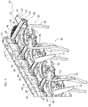
Figure 1 is a perspective view of a part of a rotary harrow according to the present invention, -
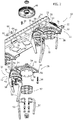
Figure 2 is a partially exploded perspective view ofFigure 1 , -
Figure 3 is a cross-section according to the line III-III ofFigure 1 , and -
Figure 4 is a perspective view analogous toFigure 1 illustrating a second embodiment of the invention. -
Figure 1 illustrates a section of a rotary harrow according to the present invention. With reference toFigure 3 , the rotary harrow comprises an elongated box-shaped frame 10 including an elongated channel-shaped profile 12 and an elongated closing plate 14 (Figure 3 ) fixed to theelongated profile 12 by means ofscrews 16. The elongated channel-shaped profile 12 is formed of a bent steel sheet and comprises abottom wall 18, twolateral sides 20, and twoedges 22. Thelateral sides 20 are orthogonal to thebottom wall 18 and parallel to each other. Theedges 22 are formed by ends bent outwardly by 90° from thelateral sides 20. Theedges 22 are provided withholes 24 in which thescrews 16 are engaged for fixing theclosing plate 14 to theelongated profile 12 - With reference to
Figures 2 and3 , thebottom wall 18 of the elongated channel-shaped profile 12 is provided with an array ofcircular openings 26. Fixingholes 28 are arranged around eachcircular opening 26. For example, fourfixing holes 28 may be provided around eachcircular opening 26. - With reference to
Figures 1 to 3 , the rotary harrow comprises a plurality ofsoil working assemblies 30 carried by the elongated channel-shaped profile 12. Eachsoil working assembly 30 is comprised of asupport 32 formed by a robust body made of a high resistance metal such as steel or cast iron. Eachsupport 32 comprises ahollow portion 34 and aradial flange 36. Thehollow portion 34 of eachsupport 32 extends partly inside theelongated frame 10 through a respectivecircular opening 26 of thebottom wall 18. Theradial flange 36 is located outside theelongated frame 10 and rests on the outer face of thebottom wall 18. Eachsupport 32 is fixed to the elongated channel-shaped profile 12 by means ofscrews 38 which extend throughrespective fixing holes 28 of thebottom wall 18 and engage respective threadedholes 40 formed in theradial flange 36. - Each
soil working assembly 30 comprises a rotary shaft 42 (Figure 3 ) which extends through thehollow portion 34 of therespective support 32. Eachrotary shaft 42 is rotatably supported by twobearings 44 carried by thehollow portion 34 of thesupport 32. Eachrotary shaft 42 has one end located inside theelongated frame 10 to which atoothed wheel 46 is fixed, and ahead 48 located outside of theelongated frame 10 to which anattachment device 50 is fixed for attaching theteeth 52. Theattachment device 50 can be, for example, of the type described in the documentEP-A-1419682 by the same applicant. Thetoothed wheels 46 of the varioussoil working assemblies 30 mesh with each other to transmit the rotating movement to therotary shafts 42 starting from a single transmission box (not illustrated) intended to be connected to the PTO of an agricultural tractor - With reference to
Figures 1 to 3 , theradial flange 36 of eachsupport 32 has at least twoextensions 54 which extend in the transverse direction outside of thelateral sides 20 of theelongated profile 12. Theextensions 54 of eachradial flange 36 are fixed tolateral sides 20 opposite to theelongated profile 12. - In the embodiment illustrated in
Figures 1 to 3 , eachradial flange 36 is essentially rhombus-shaped, with two vertices with an acute angle forming theextensions 54. Eachextension 54 has a through-hole 56 engaged by arespective fixing screw 58. Theextensions 54 of theradial flanges 36 are fixed at C-shaped brackets 60 welded on the outer faces of thelateral sides 20 of theelongated profile 12. The end of the C-shaped brackets 60 are welded to thesides 20, so that eachbracket 60 forms aslot 62 parallel to the respectivelateral side 20. Eachfixing screw 58 engages a respective threadedhole 64 formed in aprismatic block 66 located on the opposite side of theflange 60 relative to therespective extension 54. Eachprismatic block 66 has two threadedholes 64 which are engaged by thefixing screws 58 of twoextensions 54 belonging to twosoil working assemblies 30 adjacent to each other. The soil workingassemblies 30 located at opposite ends of theelongated frame 10 have anextension 54 which is not fixed to a corresponding extension of a working assembly. - As is seen in
Figures 1 and2 , theradial flanges 36 are orientated so that in each adjacent pair ofsoil working assemblies 30, twoextensions 54 belonging to two differentsoil working assemblies 30 are fixed to thesame bracket 60 and to the sameprismatic block 66. - The fact that the supports 32 of the
soil working assemblies 30 are fixed to thesides 20 of theelongated profile 12 increases the torsional strength of theprofile 12, given that thesides 20 contribute to supporting the torsional stresses between the adjacent workingassemblies 30. A very important additional increase of the strength of theprofile 12 is obtained thanks to the fact that the supports 32 of each pair of adjacent workingassemblies 30 are fixed to each other. In fact, the supports 32 interconnected to each other as well as to theframe 10 render theframe 10 more rigid compared to the solutions according to the prior art in which each support transfers the stresses coming from the soil solely to the frame. - The solution according to the present invention allows avoiding the use of a reinforcing plate that, in the solutions according to the prior art, is welded onto the inner face of the bottom wall of the elongated channel-shaped profile. The solution according to the invention also allows reduction of the thickness of the elongated channel-shaped profile from a thickness of 8 mm (used in the solutions according to the prior art) to a thickness of 5-6 mm. Despite reducing the thickness of the elongated channel-shaped profile and eliminating the reinforcing plate on the bottom wall, the solution according to the present invention allows a higher torsional strength to be obtained.
-
Figure 4 illustrates a second embodiment of the present invention. The elements corresponding to those previously described are indicated with the same reference numerals. - In the variant of
Figure 4 , eachradial flange 36 has fourextensions 54 fixed pairwise to oppositelateral sides 20 of theelongated profile 12. The twoextensions 54 of eachradial flange 36 located on thesame side 20 are fixed to twoadjacent brackets 60. In this case, eachradial flange 36 is fixed to aradial flange 36 of an adjacentsoil working assembly 30 by means of twoextensions 54 located on opposite sides of theframe 18. This solution allows an even greater increase of the torsional strength to be obtained and can be used in the case of larger harrows. - Of course, without prejudice to the principle of the invention, the construction details and the embodiments may widely vary with respect to what is described and illustrated, without departing from the scope of the invention as defined by the following claims that follow.
Claims (8)
- A rotary harrow comprising:- an elongated box-shaped frame (10) including an elongated channel-shaped profile (12) having a bottom wall (18) and two lateral sides (20),- a plurality of soil working assemblies (30) carried by said elongated profile (12), wherein each of said soil working assemblies (30) comprises a support (32) having a hollow portion (34), a rotary shaft (42) rotatably carried by the support (32), a toothed wheel (46) fixed to one end of the rotary shaft (42) located within said elongated frame (10) and a tooth attachment device (50) fixed to a head (48) of said rotary shaft (42) located outside of said frame (10),characterized in that the hollow portion (34) of each of said supports (32) extends partially inside said frame (10) and in that each of said supports (32) is provided with a radial flange (36) located outside the elongated frame (10) and fixed by means of screws (38) to the bottom wall (18) of the elongated profile (12), the radial flange (36) of each support (32) having at least two extensions (54) that protrude in a transverse direction outwardly from the respective lateral sides (20), said extensions (54) being fixed to opposite lateral sides (20) of said elongated profile (12) .
- A rotary harrow according to claim 1, wherein at least two extensions (54) belonging to two radial flanges (36) of each pair of adjacent soil working assemblies (30) are fixed to each other.
- A rotary harrow according to claim 1 or claim 2, wherein said extensions (54) are fixed to C-shaped brackets (60) welded to the lateral sides (20) of said elongated profile (12).
- A rotary harrow according to claim 3, wherein said extensions (54) are fixed to respective sides (20) by screws (58) which extend through respective slots (62) formed by said C-shaped brackets (60).
- A rotary harrow according to claim 4, wherein each of said screws (58) engages a threaded hole (64) of a respective prismatic block (66).
- A rotary harrow according to claim 5, wherein at least two extensions (54) belonging to two radial flanges (36) of each pair of adjacent soil working assemblies (30) are fixed to each other by means of respective screws (58) which extend through the same slot (62) and engage the same prismatic block (66).
- A rotary harrow according to any one of the preceding claims, wherein each of said radial flanges (36) is essentially rhombus-shaped with two vertices with an acute angle forming said extensions (54).
- A rotary harrow according to any of claims 1 to 6, wherein each of said radial flanges (36) has four extensions (54) fixed pairwise to respective opposite lateral sides (20) of said elongated profile (12).
Applications Claiming Priority (1)
| Application Number | Priority Date | Filing Date | Title |
|---|---|---|---|
| ITTO20140771 | 2014-09-29 |
Publications (2)
| Publication Number | Publication Date |
|---|---|
| EP3000293A1 EP3000293A1 (en) | 2016-03-30 |
| EP3000293B1 true EP3000293B1 (en) | 2018-11-07 |
Family
ID=51982677
Family Applications (1)
| Application Number | Title | Priority Date | Filing Date |
|---|---|---|---|
| EP15186195.2A Active EP3000293B1 (en) | 2014-09-29 | 2015-09-22 | A rotary harrow with improved strength |
Country Status (1)
| Country | Link |
|---|---|
| EP (1) | EP3000293B1 (en) |
Families Citing this family (1)
| Publication number | Priority date | Publication date | Assignee | Title |
|---|---|---|---|---|
| CN106879267A (en) * | 2017-03-03 | 2017-06-23 | 河北省农业机械化研究所有限公司 | A kind of orchard furrowing fertilizer applicator of energy-saving fertilizer |
Family Cites Families (4)
| Publication number | Priority date | Publication date | Assignee | Title |
|---|---|---|---|---|
| FR2559013B1 (en) * | 1977-12-02 | 1990-01-26 | Patent Concern Nv | SOIL WORKING MACHINE |
| FR2441995A1 (en) * | 1978-11-24 | 1980-06-20 | Kuhn Sa | IMPROVEMENT WITH ROTARY HERSE TURPIES |
| ITTO20020976A1 (en) | 2002-11-12 | 2004-05-13 | Frandent Di Ezio Bruno | TOOL HOLDER GROUP FOR A LAND WORKING MACHINE AND TOOL FOR THIS GROUP |
| DE102008020901A1 (en) * | 2008-04-25 | 2009-10-29 | Amazonen-Werke H. Dreyer Gmbh & Co. Kg | Tillage machine |
-
2015
- 2015-09-22 EP EP15186195.2A patent/EP3000293B1/en active Active
Non-Patent Citations (1)
| Title |
|---|
| None * |
Also Published As
| Publication number | Publication date |
|---|---|
| EP3000293A1 (en) | 2016-03-30 |
Similar Documents
| Publication | Publication Date | Title |
|---|---|---|
| US8074914B2 (en) | Crushing bucket | |
| US9888621B2 (en) | Blade assembly flange | |
| EP3000293B1 (en) | A rotary harrow with improved strength | |
| AU2023274120B2 (en) | Agricultural tilting bearing assembly and improved support bracket for connecting the same to agricultural equipment | |
| US8491430B1 (en) | Roller chain assembly | |
| US4411322A (en) | Cultivating machine rotor | |
| BRPI0710825B1 (en) | Billet Guide Roll | |
| US1829605A (en) | Roller for crushing clods | |
| JP6405085B2 (en) | Tillage nail | |
| DE102012214996A1 (en) | Centrifugal pendulum for vibration damping in power train of motor vehicle, has outer flange connected with inner flange such that outer flange is pivotable against rotational axis | |
| CN108551776B (en) | Prevent rolling up grass pivot and agricultural cultivated land weeder | |
| JP6038729B2 (en) | Chain and connecting pin | |
| JP2014030363A (en) | Ground leveling member for agricultural working machine | |
| JP6038723B2 (en) | Rotary tiller | |
| JP5782277B2 (en) | Power transmission unit and method of mounting power transmission mechanism | |
| JP2015139427A (en) | Rotary tillage device | |
| JP2019030228A (en) | Agricultural machine | |
| JP5863169B2 (en) | Agricultural machine | |
| US1341539A (en) | Harrow | |
| JP7094214B2 (en) | Walking work machine | |
| CA3224035C (en) | Agricultural tilting bearing assembly and improved support bracket for connecting the same to agricultural equipment | |
| CN208210588U (en) | A kind of tea place rotary cultivator | |
| NZ579004A (en) | A feed roll for a harvester head and a method for manufacturing a feed roll | |
| JP4315390B2 (en) | Winding prevention member and tilling claw shaft assembly | |
| JP6134260B2 (en) | Cigarette prevention device for rotary tillers |
Legal Events
| Date | Code | Title | Description |
|---|---|---|---|
| PUAI | Public reference made under article 153(3) epc to a published international application that has entered the european phase |
Free format text: ORIGINAL CODE: 0009012 |
|
| AK | Designated contracting states |
Kind code of ref document: A1 Designated state(s): AL AT BE BG CH CY CZ DE DK EE ES FI FR GB GR HR HU IE IS IT LI LT LU LV MC MK MT NL NO PL PT RO RS SE SI SK SM TR |
|
| AX | Request for extension of the european patent |
Extension state: BA ME |
|
| 17P | Request for examination filed |
Effective date: 20160610 |
|
| RBV | Designated contracting states (corrected) |
Designated state(s): AL AT BE BG CH CY CZ DE DK EE ES FI FR GB GR HR HU IE IS IT LI LT LU LV MC MK MT NL NO PL PT RO RS SE SI SK SM TR |
|
| RIC1 | Information provided on ipc code assigned before grant |
Ipc: A01B 33/06 20060101AFI20180618BHEP |
|
| GRAP | Despatch of communication of intention to grant a patent |
Free format text: ORIGINAL CODE: EPIDOSNIGR1 |
|
| STAA | Information on the status of an ep patent application or granted ep patent |
Free format text: STATUS: GRANT OF PATENT IS INTENDED |
|
| INTG | Intention to grant announced |
Effective date: 20180727 |
|
| RIN1 | Information on inventor provided before grant (corrected) |
Inventor name: BRUNO, EZIO |
|
| GRAS | Grant fee paid |
Free format text: ORIGINAL CODE: EPIDOSNIGR3 |
|
| GRAA | (expected) grant |
Free format text: ORIGINAL CODE: 0009210 |
|
| STAA | Information on the status of an ep patent application or granted ep patent |
Free format text: STATUS: THE PATENT HAS BEEN GRANTED |
|
| AK | Designated contracting states |
Kind code of ref document: B1 Designated state(s): AL AT BE BG CH CY CZ DE DK EE ES FI FR GB GR HR HU IE IS IT LI LT LU LV MC MK MT NL NO PL PT RO RS SE SI SK SM TR |
|
| REG | Reference to a national code |
Ref country code: GB Ref legal event code: FG4D |
|
| REG | Reference to a national code |
Ref country code: CH Ref legal event code: EP Ref country code: AT Ref legal event code: REF Ref document number: 1060974 Country of ref document: AT Kind code of ref document: T Effective date: 20181115 |
|
| REG | Reference to a national code |
Ref country code: DE Ref legal event code: R096 Ref document number: 602015019415 Country of ref document: DE |
|
| REG | Reference to a national code |
Ref country code: IE Ref legal event code: FG4D |
|
| REG | Reference to a national code |
Ref country code: NL Ref legal event code: MP Effective date: 20181107 |
|
| REG | Reference to a national code |
Ref country code: LT Ref legal event code: MG4D |
|
| REG | Reference to a national code |
Ref country code: AT Ref legal event code: MK05 Ref document number: 1060974 Country of ref document: AT Kind code of ref document: T Effective date: 20181107 |
|
| PG25 | Lapsed in a contracting state [announced via postgrant information from national office to epo] |
Ref country code: FI Free format text: LAPSE BECAUSE OF FAILURE TO SUBMIT A TRANSLATION OF THE DESCRIPTION OR TO PAY THE FEE WITHIN THE PRESCRIBED TIME-LIMIT Effective date: 20181107 Ref country code: IS Free format text: LAPSE BECAUSE OF FAILURE TO SUBMIT A TRANSLATION OF THE DESCRIPTION OR TO PAY THE FEE WITHIN THE PRESCRIBED TIME-LIMIT Effective date: 20190307 Ref country code: LT Free format text: LAPSE BECAUSE OF FAILURE TO SUBMIT A TRANSLATION OF THE DESCRIPTION OR TO PAY THE FEE WITHIN THE PRESCRIBED TIME-LIMIT Effective date: 20181107 Ref country code: BG Free format text: LAPSE BECAUSE OF FAILURE TO SUBMIT A TRANSLATION OF THE DESCRIPTION OR TO PAY THE FEE WITHIN THE PRESCRIBED TIME-LIMIT Effective date: 20190207 Ref country code: HR Free format text: LAPSE BECAUSE OF FAILURE TO SUBMIT A TRANSLATION OF THE DESCRIPTION OR TO PAY THE FEE WITHIN THE PRESCRIBED TIME-LIMIT Effective date: 20181107 Ref country code: ES Free format text: LAPSE BECAUSE OF FAILURE TO SUBMIT A TRANSLATION OF THE DESCRIPTION OR TO PAY THE FEE WITHIN THE PRESCRIBED TIME-LIMIT Effective date: 20181107 Ref country code: LV Free format text: LAPSE BECAUSE OF FAILURE TO SUBMIT A TRANSLATION OF THE DESCRIPTION OR TO PAY THE FEE WITHIN THE PRESCRIBED TIME-LIMIT Effective date: 20181107 Ref country code: NO Free format text: LAPSE BECAUSE OF FAILURE TO SUBMIT A TRANSLATION OF THE DESCRIPTION OR TO PAY THE FEE WITHIN THE PRESCRIBED TIME-LIMIT Effective date: 20190207 Ref country code: AT Free format text: LAPSE BECAUSE OF FAILURE TO SUBMIT A TRANSLATION OF THE DESCRIPTION OR TO PAY THE FEE WITHIN THE PRESCRIBED TIME-LIMIT Effective date: 20181107 |
|
| PG25 | Lapsed in a contracting state [announced via postgrant information from national office to epo] |
Ref country code: PT Free format text: LAPSE BECAUSE OF FAILURE TO SUBMIT A TRANSLATION OF THE DESCRIPTION OR TO PAY THE FEE WITHIN THE PRESCRIBED TIME-LIMIT Effective date: 20190307 Ref country code: AL Free format text: LAPSE BECAUSE OF FAILURE TO SUBMIT A TRANSLATION OF THE DESCRIPTION OR TO PAY THE FEE WITHIN THE PRESCRIBED TIME-LIMIT Effective date: 20181107 Ref country code: GR Free format text: LAPSE BECAUSE OF FAILURE TO SUBMIT A TRANSLATION OF THE DESCRIPTION OR TO PAY THE FEE WITHIN THE PRESCRIBED TIME-LIMIT Effective date: 20190208 Ref country code: RS Free format text: LAPSE BECAUSE OF FAILURE TO SUBMIT A TRANSLATION OF THE DESCRIPTION OR TO PAY THE FEE WITHIN THE PRESCRIBED TIME-LIMIT Effective date: 20181107 Ref country code: SE Free format text: LAPSE BECAUSE OF FAILURE TO SUBMIT A TRANSLATION OF THE DESCRIPTION OR TO PAY THE FEE WITHIN THE PRESCRIBED TIME-LIMIT Effective date: 20181107 Ref country code: NL Free format text: LAPSE BECAUSE OF FAILURE TO SUBMIT A TRANSLATION OF THE DESCRIPTION OR TO PAY THE FEE WITHIN THE PRESCRIBED TIME-LIMIT Effective date: 20181107 |
|
| PG25 | Lapsed in a contracting state [announced via postgrant information from national office to epo] |
Ref country code: CZ Free format text: LAPSE BECAUSE OF FAILURE TO SUBMIT A TRANSLATION OF THE DESCRIPTION OR TO PAY THE FEE WITHIN THE PRESCRIBED TIME-LIMIT Effective date: 20181107 Ref country code: DK Free format text: LAPSE BECAUSE OF FAILURE TO SUBMIT A TRANSLATION OF THE DESCRIPTION OR TO PAY THE FEE WITHIN THE PRESCRIBED TIME-LIMIT Effective date: 20181107 Ref country code: IT Free format text: LAPSE BECAUSE OF FAILURE TO SUBMIT A TRANSLATION OF THE DESCRIPTION OR TO PAY THE FEE WITHIN THE PRESCRIBED TIME-LIMIT Effective date: 20181107 Ref country code: PL Free format text: LAPSE BECAUSE OF FAILURE TO SUBMIT A TRANSLATION OF THE DESCRIPTION OR TO PAY THE FEE WITHIN THE PRESCRIBED TIME-LIMIT Effective date: 20181107 |
|
| REG | Reference to a national code |
Ref country code: DE Ref legal event code: R097 Ref document number: 602015019415 Country of ref document: DE |
|
| PG25 | Lapsed in a contracting state [announced via postgrant information from national office to epo] |
Ref country code: SK Free format text: LAPSE BECAUSE OF FAILURE TO SUBMIT A TRANSLATION OF THE DESCRIPTION OR TO PAY THE FEE WITHIN THE PRESCRIBED TIME-LIMIT Effective date: 20181107 Ref country code: RO Free format text: LAPSE BECAUSE OF FAILURE TO SUBMIT A TRANSLATION OF THE DESCRIPTION OR TO PAY THE FEE WITHIN THE PRESCRIBED TIME-LIMIT Effective date: 20181107 Ref country code: EE Free format text: LAPSE BECAUSE OF FAILURE TO SUBMIT A TRANSLATION OF THE DESCRIPTION OR TO PAY THE FEE WITHIN THE PRESCRIBED TIME-LIMIT Effective date: 20181107 Ref country code: SM Free format text: LAPSE BECAUSE OF FAILURE TO SUBMIT A TRANSLATION OF THE DESCRIPTION OR TO PAY THE FEE WITHIN THE PRESCRIBED TIME-LIMIT Effective date: 20181107 |
|
| PLBE | No opposition filed within time limit |
Free format text: ORIGINAL CODE: 0009261 |
|
| STAA | Information on the status of an ep patent application or granted ep patent |
Free format text: STATUS: NO OPPOSITION FILED WITHIN TIME LIMIT |
|
| 26N | No opposition filed |
Effective date: 20190808 |
|
| PG25 | Lapsed in a contracting state [announced via postgrant information from national office to epo] |
Ref country code: SI Free format text: LAPSE BECAUSE OF FAILURE TO SUBMIT A TRANSLATION OF THE DESCRIPTION OR TO PAY THE FEE WITHIN THE PRESCRIBED TIME-LIMIT Effective date: 20181107 |
|
| PG25 | Lapsed in a contracting state [announced via postgrant information from national office to epo] |
Ref country code: TR Free format text: LAPSE BECAUSE OF FAILURE TO SUBMIT A TRANSLATION OF THE DESCRIPTION OR TO PAY THE FEE WITHIN THE PRESCRIBED TIME-LIMIT Effective date: 20181107 |
|
| REG | Reference to a national code |
Ref country code: DE Ref legal event code: R119 Ref document number: 602015019415 Country of ref document: DE |
|
| PG25 | Lapsed in a contracting state [announced via postgrant information from national office to epo] |
Ref country code: MC Free format text: LAPSE BECAUSE OF FAILURE TO SUBMIT A TRANSLATION OF THE DESCRIPTION OR TO PAY THE FEE WITHIN THE PRESCRIBED TIME-LIMIT Effective date: 20181107 |
|
| REG | Reference to a national code |
Ref country code: CH Ref legal event code: PL |
|
| PG25 | Lapsed in a contracting state [announced via postgrant information from national office to epo] |
Ref country code: IE Free format text: LAPSE BECAUSE OF NON-PAYMENT OF DUE FEES Effective date: 20190922 Ref country code: CH Free format text: LAPSE BECAUSE OF NON-PAYMENT OF DUE FEES Effective date: 20190930 Ref country code: DE Free format text: LAPSE BECAUSE OF NON-PAYMENT OF DUE FEES Effective date: 20200401 Ref country code: LI Free format text: LAPSE BECAUSE OF NON-PAYMENT OF DUE FEES Effective date: 20190930 Ref country code: LU Free format text: LAPSE BECAUSE OF NON-PAYMENT OF DUE FEES Effective date: 20190922 |
|
| REG | Reference to a national code |
Ref country code: BE Ref legal event code: MM Effective date: 20190930 |
|
| PG25 | Lapsed in a contracting state [announced via postgrant information from national office to epo] |
Ref country code: BE Free format text: LAPSE BECAUSE OF NON-PAYMENT OF DUE FEES Effective date: 20190930 |
|
| GBPC | Gb: european patent ceased through non-payment of renewal fee |
Effective date: 20190922 |
|
| PG25 | Lapsed in a contracting state [announced via postgrant information from national office to epo] |
Ref country code: GB Free format text: LAPSE BECAUSE OF NON-PAYMENT OF DUE FEES Effective date: 20190922 |
|
| PG25 | Lapsed in a contracting state [announced via postgrant information from national office to epo] |
Ref country code: CY Free format text: LAPSE BECAUSE OF FAILURE TO SUBMIT A TRANSLATION OF THE DESCRIPTION OR TO PAY THE FEE WITHIN THE PRESCRIBED TIME-LIMIT Effective date: 20181107 |
|
| PG25 | Lapsed in a contracting state [announced via postgrant information from national office to epo] |
Ref country code: HU Free format text: LAPSE BECAUSE OF FAILURE TO SUBMIT A TRANSLATION OF THE DESCRIPTION OR TO PAY THE FEE WITHIN THE PRESCRIBED TIME-LIMIT; INVALID AB INITIO Effective date: 20150922 Ref country code: MT Free format text: LAPSE BECAUSE OF FAILURE TO SUBMIT A TRANSLATION OF THE DESCRIPTION OR TO PAY THE FEE WITHIN THE PRESCRIBED TIME-LIMIT Effective date: 20181107 |
|
| PG25 | Lapsed in a contracting state [announced via postgrant information from national office to epo] |
Ref country code: MK Free format text: LAPSE BECAUSE OF FAILURE TO SUBMIT A TRANSLATION OF THE DESCRIPTION OR TO PAY THE FEE WITHIN THE PRESCRIBED TIME-LIMIT Effective date: 20181107 |
|
| PGFP | Annual fee paid to national office [announced via postgrant information from national office to epo] |
Ref country code: FR Payment date: 20240925 Year of fee payment: 10 |