EP3000292A1 - Bodenwalze - Google Patents
Bodenwalze Download PDFInfo
- Publication number
- EP3000292A1 EP3000292A1 EP15401092.0A EP15401092A EP3000292A1 EP 3000292 A1 EP3000292 A1 EP 3000292A1 EP 15401092 A EP15401092 A EP 15401092A EP 3000292 A1 EP3000292 A1 EP 3000292A1
- Authority
- EP
- European Patent Office
- Prior art keywords
- support tube
- rings
- spacer elements
- soil compaction
- soil
- Prior art date
- Legal status (The legal status is an assumption and is not a legal conclusion. Google has not performed a legal analysis and makes no representation as to the accuracy of the status listed.)
- Granted
Links
Images

Classifications
-
- A—HUMAN NECESSITIES
- A01—AGRICULTURE; FORESTRY; ANIMAL HUSBANDRY; HUNTING; TRAPPING; FISHING
- A01B—SOIL WORKING IN AGRICULTURE OR FORESTRY; PARTS, DETAILS, OR ACCESSORIES OF AGRICULTURAL MACHINES OR IMPLEMENTS, IN GENERAL
- A01B29/00—Rollers
- A01B29/04—Rollers with non-smooth surface formed of rotatably-mounted rings or discs or with projections or ribs on the roller body; Land packers
- A01B29/041—Rollers with non-smooth surface formed of rotatably-mounted rings or discs or with projections or ribs on the roller body; Land packers of "Cambridge"-type, i.e. the soil-pressing rings being stacked on a shaft
- A01B29/043—Tyre-packers
Definitions
- the invention relates to a bottom roller according to the preamble of claim 1.
- Such a bottom roller is in the EP 0 861 577 B1 described.
- This bottom roller consists of spaced-apart circumferential Bodenverfest Whilesringen between which circumferential spacers are arranged.
- the alternately arranged on the central support tube Bodenverfest Drsringe and spacer elements are pressed against each other by means of suitable clamping elements. Because the heel elements press exclusively against the soil consolidation rings, no defined and sufficiently uniform tension of the soil stabilization rings and the spacing elements to each other is ensured because the elastic material of the soil stabilization rings is located between the spacers.
- the invention is based on the object to achieve a simplification of the installation and a better positioning of the soil stabilization rings on the support tube in a simple manner.
- This object of the invention achieved in that the Bodenverfest onlysringe in the region of the central support tube and the spacer a plurality of spaced apart and over the entire width of the Bodenverdichtungsringe extending recesses, that the spacer elements with the recesses corresponding and in the assembled state in the recess summarizing approaches exhibit.
- the lugs on the spacer elements have half the width of the spacing of the spacer elements in the assembled final state of the spacer elements and the Bodenverfest Trentsringe on the support tube of the bottom roller. Thus, only very few different parts need to be kept.
- a defined arrangement of soil compaction rings to each other and a uniform tension of these elements is achieved in that the lugs on the adjacent spacer elements in the final assembled state of the spacer elements and the Bodenverfest Trentsringe on the support tube of the bottom roller abut each other directly with their end faces.
- a simple embodiment of the soil compaction rings and the spacer elements is achieved in that the soil compaction rings made of plastic or rubber, that the spacer elements of a stiffer material than the soil compaction rings.
- the soil compaction rings are configured in the region adjacent to the support tube such that the material of the soil compaction rings by compressing the spacers and the soil compaction rings in the axial direction to jam the Soil compaction rings are pressed on the support tube against the support tube.
- the bottom roller consists of the support tube 1, the alternately arranged on the support tube 1 Bodenverfest Trentsringe 2 and spacers 3.
- the Bodenverfest Whilesringe 2 and the spacers 3 are clamped in a known and therefore in a manner not shown against each other by means of corresponding clamping elements, so that they laterally immovable the support tube 1 are arranged.
- the bottom roller is so-called wedge ring roller formed.
- bearing elements for rotatably supporting the support tube 1 are arranged in a support frame, not shown, in a known and therefore not shown manner.
- the soil stabilization rings 2 are arranged on the central support tube 1 by spaced therebetween spacer elements 3 at defined intervals spaced from each other.
- the spacer elements 3 have a substantially smaller outer diameter than the soil compaction rings 2.
- the soil compaction rings 2 and the spacers 3 have in the unstressed state to each other an inner diameter which is slightly larger than the outer diameter of the support tube 1. This allows the spacers 3 and the soil compaction 2 easily pushed onto the support tube 1.
- the soil compaction rings 2 have a wedge-shaped shape in their outer peripheral region 4. In their region 5, which is adjacent to the support tube 1, the soil compacting rings 2 have a dovetail-shaped shape 7 as seen through the annular groove 6 arranged on both sides.
- the Soil consolidation rings 2 in the support tube 1 adjacent region 5 and in the region of the spacers 3 a plurality of spaced apart and over the entire width B of the soil compaction rings 2 extending recesses 8.
- the spacers 3 have with the recesses 8 corresponding and in the assembled state in the recesses 8 summarizing lugs 9.
- the soil compaction rings 2 are made of a plastic or rubber, while the spacers 3 are made of a stiffer material than the soil compaction rings 2.
- the soil compaction rings 2 have a circumferential cavity 12.
- the soil compaction rings 2 are configured in the region 5 adjacent to the support tube 1 such that the material of the soil compaction rings 2 by the meeting of the spacers 3 and the soil compaction rings 2 in the axial direction by means not shown clamping elements for clamping the soil compaction rings 2 on the support tube 1 against the support tube 1 are pressed.
Landscapes
- Life Sciences & Earth Sciences (AREA)
- Engineering & Computer Science (AREA)
- Mechanical Engineering (AREA)
- Soil Sciences (AREA)
- Environmental Sciences (AREA)
- Investigation Of Foundation Soil And Reinforcement Of Foundation Soil By Compacting Or Drainage (AREA)
Abstract
Description
- Die Erfindung betrifft eine Bodenwalze gemäß des Oberbegriffes des Patentanspruches 1.
- Eine derartige Bodenwalze ist in der
EP 0 861 577 B1 beschrieben. Diese Bodenwalze besteht aus beabstandet zueinander angeordneten umlaufenden Bodenverfestigungsringen, zwischen denen umlaufende Abstandselemente angeordnet sind. Die abwechselnd auf dem zentralen Tragrohr angeordneten Bodenverfestigungsringe und Abstandselemente werden mittels geeigneter Spannelemente gegeneinandergedrückt. Weil die Absatzelemente ausschließlich gegen die Bodenverfestigungsringe drücken, ist keine definierte und ausreichend gleichmäßige Verspannung der Bodenverfestigungsringe und der Abstand Elemente zueinander gewährleistet, weil sich das elastische Material der Bodenverfestigungsringe zwischen den Abstandselementen befindet. - Der Erfindung liegt die Aufgabe zu Grunde, eine Vereinfachung der Montage und eine bessere Positionierung der Bodenverfestigungsringe auf dem Tragrohr in einfacher Weise zu erreichen.
- Diese Aufgabe der erfindungsgemäß dadurch gelöst, dass die Bodenverfestigungsringe im Bereich des zentralen Tragrohres und der Abstandselemente mehrere beabstandet zueinander angeordnete und über die gesamte Breite der Bodenverdichtungsringe sich erstreckende Aussparungen aufweisen, dass die Abstandselemente mit den Aussparungen korrespondierende und im montierten Zustand in die Aussparung fassende Ansätze aufweisen.
- Infolge dieser Maßnahmen erfolgt eine definierte Verspannung der Bodenverdichtungsringe durch die Abstandselemente auf dem Tragrohr, weil die durch die Aussparungen in den Bodenverdichtungsringen hindurchgehenden und aneinander anliegenden Ansätze der Abstandelemente unmittelbar, ohne die zwischen Lage des elastischen Materiales der Bodenverfestigungsringe, aneinander Anliegen und so gegeneinander verspannt werden. Somit wird ein Formschluss durch das unmittelbare aneinander Anliegen der Ansätze der Abstandelemente erzwungen. Auch der Abstand der Bodenverdichtungsringe zueinander wird hierdurch in der vorgeschriebenen Weise gewährleistet.
- Um möglichst viele gleiche Teile zu erhalten, ist vorgesehen, dass die Ansätze an den Abstandselementen die halbe Breite des Abstandes der Abstandselemente im montierten Endzustand der Abstandselemente und der Bodenverfestigungsringe auf dem Tragrohr der Bodenwalze aufweisen. Somit brauchen nur sehr wenige verschiedene Teile vorgehalten zu werden.
- Eine definierte Anordnung der Bodenverdichtungsringe zueinander und eine gleichmäßige Verspannung dieser Elemente wird dadurch erreicht, dass die Ansätze an den benachbarten Abstandselementen im montierten Endzustand der Abstandselemente und der Bodenverfestigungsringe auf dem Tragrohr der Bodenwalze mit ihren Stirnseiten unmittelbar aneinander anliegen.
- Eine einfache Ausgestaltung der Bodenverdichtungsringe und der Abstandselemente wird dadurch erreicht, dass die Bodenverdichtungsringe aus Kunststoff oder Gummi bestehenden, dass die Abstandselemente aus einem steiferen Material als die Bodenverdichtungsringe bestehen.
- Eine vorteilhafte Ausgestaltung und Selbstreinigung der Bodenverdichtungsringe ergibt sich dadurch, dass die Bodenverdichtungsringe einen umlaufenden Hohlraum aufweisen.
- Um eine noch weitere verbesserte verschiebesichere Anordnung der Bodenverdichtungsringe auf dem Tragrohr zu erreichen, ist vorgesehen, dass die Bodenverdichtungsringe in dem dem Tragrohr benachbarten Bereich derart ausgestaltet sind, dass das Material der Bodenverdichtungsringe durch das Zusammenpressen der Abstandselemente und der Bodenverdichtungsringe in axialer Richtung zum Verklemmen der Bodenverdichtungsringe auf dem Tragrohr gegen das Tragrohr gedrückt werden.
- Weitere Einzelheiten der Erfindung sind der Beispielsbeschreibung und den Zeichnungen zu entnehmen. Die Zeichnungen zeigen
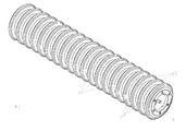
- Fig.1
- die Bodenwalze ohne Tragrahmen in perspektivischer Darstellung,
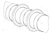
- Fig.2
- die Anordnung der Bodenverfestigungsringe und Abstandselemente auf dem Tragrohr der Bodenwalze in Explosionsdarstellung, perspektivischer Darstellung im Teilansicht und vergrößertem Maßstab und
- Fig.3
- die Zuordnung der Bodenverdichtungsringe und der Abstandselemente im Schnitt.
- Die Bodenwalze besteht aus dem Tragrohr 1, den abwechselnd zueinander auf dem Tragrohr 1 angeordneten Bodenverfestigungsringe 2 und Abstandselementen 3. Die Bodenverfestigungsringe 2 und die Abstandselemente 3 sind in bekannter und daher in nicht dargestellter Weise gegeneinander mittels entsprechenden Spannelementen verspannt, so dass sie seitlich unverschiebbar auf dem Tragrohr 1 angeordnet sind. Die Bodenwalze ist also genannte Keilringwalze ausgebildet. Am Ende des Tragrohres 1 sind in bekannter und daher in nicht dargestellter Weise Lagerelemente zur drehbaren Lagerung des Tragrohres 1 in einem nicht dargestellten Tragrahmen angeordnet.
- Die Bodenverfestigungsringe 2 sind auf dem zentralen Tragrohr 1 durch die zwischen ihnen angeordneten Abstandselemente 3 in definierten Abständen beabstandet voneinander angeordnet. Die Abstandselemente 3 weisen einen wesentlich kleineren Außendurchmesser als die Bodenverdichtungsringe 2 auf.
- Die Bodenverdichtungsringe 2 und die Abstandselemente 3 weisen im unverspannten Zustand zueinander einen Innendurchmesser auf, der etwas größer ist als der Außendurchmesser des Tragrohres 1. Hierdurch lassen sich die Abstandselemente 3 und die Bodenverdichtungsringe 2 leicht auf das Tragrohr 1 aufschieben. Die Bodenverdichtungsringe 2 weisen in ihrem äußeren Umfangsbereich 4 eine keilförmige Form auf. In ihrem dem Tragrohr 1 benachbarten Bereich 5 weisen die Bodenverdichtungsringe 2 durch die beidseitig angeordnete ringförmige Nut 6 einem Querschnitt gesehen schwalbenschwanzförmige Form 7 auf. Des Weiteren weisen die Bodenverfestigungsringe 2 in dem Tragrohr 1 benachbarten Bereich 5 und im Bereich der Abstandselemente 3 mehrere beabstandet zueinander angeordnete und über die gesamte Breite B der Bodenverdichtungsringe 2 sich erstreckende Aussparungen 8 auf. Die Abstandselemente 3 weisen mit den Aussparungen 8 korrespondierende und im montierten Zustand in die Aussparungen 8 fassende Ansätze 9 auf.
- Die Ansätze 9 an den Abstandselemente 3 in weisen die halbe Breite des Abstandes der Abstandselemente 3 im montierten Zustand der Abstandselemente 3 und der Bodenverfestigungsringe 2 auf dem Tragrohr 1 der Bodenwalze auf, wie die
Fig.3 im linken Bereich 10 zeigt. Hierbei liegen die Ansätze 9 an den benachbarten Abstandselementen 3 im montierten Endzustand der Abstandselemente 3 und der Bodenverfestigungsringe 2 auf dem Tragrohr 1 der Bodenwalze mit ihren Stirnseiten 11 unmittelbar aneinander, wie ebenfalls dieFig.3 im linken Bereich 10 zeigt. - Die Bodenverdichtungsringe 2 bestehen aus einem Kunststoff oder Gummi, während die Abstandselemente 3 aus einem steiferen Material als die Bodenverdichtungsringe 2 bestehen. Die Bodenverdichtungsringe 2 weisen einen umlaufenden Hohlraum 12 auf.
- Die Bodenverdichtungsringe 2 sind in dem dem Tragrohr 1 benachbarten Bereich 5 derart ausgestaltet, dass das Material der Bodenverdichtungsringe 2 durch das Zusammentreffen der Abstandselemente 3 und der Bodenverdichtungsringe 2 in axialer Richtung mittels nicht dargestellter Spannelemente zum Verklemmen der Bodenverdichtungsringe 2 auf dem Tragrohr 1 gegen das Tragrohr 1 gedrückt werden.
Claims (6)
- Bodenwalze mit beabstandet zueinander angeordneten umlaufenden Bodenverfestigungsringen (2), welche auf einem zentralen Tragrohr (1) voneinander beabstandet angeordnet sind, wobei zwischen den Bodenverfestigungsringen (2) umlaufende Abstandselemente (3), die im Außendurchmesser wesentlich kleiner als die Bodenverdichtungsringe (2) sind, angeordnet sind, dadurch gekennzeichnet, dass die Bodenverfestigungsringe (2) im Bereich (5) des zentralen Tragrohres (1) und der Abstandselemente (3) mehrere beabstandet zueinander angeordnete und über die gesamte Breite der Bodenverdichtungsringe (2) sich erstreckende Aussparungen (8) aufweisen, dass die Abstandselemente (3) mit den Aussparungen (8) korrespondierende und im montierten Zustand in die Aussparung (8) fassende Ansätze (9) aufweisen.
- Bodenwalze nach Anspruch 1, dadurch gekennzeichnet, dass die Ansätze (3) an den Abstandselementen (3) die halbe Breite des Abstandes der Abstandselemente (3) im montierten Endzustand der Abstandselemente (3) und der Bodenverfestigungsringe (2) auf dem Tragrohr (1) der Bodenwalze aufweisen.
- Bodenwalze nach zumindest einem der vorstehenden Ansprüche, dadurch gekennzeichnet, dass die Ansätze (9) an den benachbarten Abstandselementen (3) im montierten Endzustand der Abstandselemente (3) und der Bodenverfestigungsringe (2) auf dem Tragrohr (1) der Bodenwalze mit ihren Stirnseiten (11) unmittelbar aneinander anliegen.
- Bodenwalze nach zumindest einem der vorstehenden Ansprüche, dadurch gekennzeichnet, dass die Bodenverdichtungsringe (2) aus Kunststoff oder Gummi bestehenden, dass die Abstandselemente (3) aus einem steiferen Material als die Bodenverdichtungsringe (2) bestehen.
- Bodenwalze nach zumindest einem der vorstehenden Ansprüche, dadurch gekennzeichnet, dass die Bodenverdichtungsringe (2) einen umlaufenden Hohlraum (12) aufweisen.
- Bodenwalze nach zumindest einem der vorstehenden Ansprüche, dadurch gekennzeichnet, dass die Bodenverdichtungsringe (2) in dem dem Tragrohr (1) benachbarten Bereich (5) derart ausgestaltet sind, dass das Material der Bodenverdichtungsringe (2) durch das Zusammenpressen der Abstandselemente (3) und der Bodenverdichtungsringe (2) in axialer Richtung zum Verklemmen der Bodenverdichtungsringe (2) auf dem Tragrohr (1) gegen das Tragrohr (1) gedrückt werden.
Priority Applications (1)
| Application Number | Priority Date | Filing Date | Title |
|---|---|---|---|
| PL15401092T PL3000292T3 (pl) | 2014-09-10 | 2015-09-04 | Walec rolniczy |
Applications Claiming Priority (1)
| Application Number | Priority Date | Filing Date | Title |
|---|---|---|---|
| DE102014112996.2A DE102014112996A1 (de) | 2014-09-10 | 2014-09-10 | Bodenwalze |
Publications (2)
| Publication Number | Publication Date |
|---|---|
| EP3000292A1 true EP3000292A1 (de) | 2016-03-30 |
| EP3000292B1 EP3000292B1 (de) | 2017-05-10 |
Family
ID=54360412
Family Applications (1)
| Application Number | Title | Priority Date | Filing Date |
|---|---|---|---|
| EP15401092.0A Active EP3000292B1 (de) | 2014-09-10 | 2015-09-04 | Bodenwalze |
Country Status (3)
| Country | Link |
|---|---|
| EP (1) | EP3000292B1 (de) |
| DE (1) | DE102014112996A1 (de) |
| PL (1) | PL3000292T3 (de) |
Citations (2)
| Publication number | Priority date | Publication date | Assignee | Title |
|---|---|---|---|---|
| FR2784331A1 (fr) * | 1998-10-13 | 2000-04-14 | Otico | Dispositif d'assemblage pour des pneumatiques du type semi-creux |
| EP0861577B1 (de) | 1997-02-21 | 2003-01-02 | Amazonen-Werke H. Dreyer GmbH & Co. KG | Bodenwalze |
-
2014
- 2014-09-10 DE DE102014112996.2A patent/DE102014112996A1/de not_active Withdrawn
-
2015
- 2015-09-04 PL PL15401092T patent/PL3000292T3/pl unknown
- 2015-09-04 EP EP15401092.0A patent/EP3000292B1/de active Active
Patent Citations (2)
| Publication number | Priority date | Publication date | Assignee | Title |
|---|---|---|---|---|
| EP0861577B1 (de) | 1997-02-21 | 2003-01-02 | Amazonen-Werke H. Dreyer GmbH & Co. KG | Bodenwalze |
| FR2784331A1 (fr) * | 1998-10-13 | 2000-04-14 | Otico | Dispositif d'assemblage pour des pneumatiques du type semi-creux |
Also Published As
| Publication number | Publication date |
|---|---|
| EP3000292B1 (de) | 2017-05-10 |
| DE102014112996A1 (de) | 2016-03-10 |
| PL3000292T3 (pl) | 2017-10-31 |
Similar Documents
| Publication | Publication Date | Title |
|---|---|---|
| EP1374659B1 (de) | Bodenwalze | |
| DE1928176B2 (de) | Walzenbnkettpresse zum Heißver pressen von Kohle, Erzen und ähnlichen Stoffen | |
| EP3000292B1 (de) | Bodenwalze | |
| DE20106646U1 (de) | Vorrichtung zum Filtern und Trennen von Strömungsmedien nach dem Prinzip der Ultrafiltration | |
| EP1856963A1 (de) | Landwirtschaftliche Bodenwalze | |
| EP0861577B1 (de) | Bodenwalze | |
| DE102014116449B4 (de) | Pumpe mit einem Lagerträger, einer Zwischenlaterne und einer Verstelleinrichtung | |
| DE19641317A1 (de) | Rollenbahn und Tragrolle dafür | |
| DE102017126002B3 (de) | Exzenterschneckenpumpe | |
| EP3158841B1 (de) | Bodenwalze | |
| DE3142617C2 (de) | ||
| DE1809145B1 (de) | Walze,insbesondere fuer Roste zum Reinigen von Feldfruechten | |
| DE3918751A1 (de) | Bodenwalze | |
| AT15508U1 (de) | Vorrichtung zum lösbaren Verbinden einer Zusatzradfelge mit einer Fahrzeugradfelge | |
| EP2436249A2 (de) | Landwirtschaftliche Maschine | |
| DE102017100589A1 (de) | Kettenschutz für ein Elektrofahrrad | |
| DE2604969C2 (de) | ||
| DE2243479C3 (de) | ||
| DE102015112622A1 (de) | Verdrängungskörper für eine Schlauchpumpe und Schlauchpumpe | |
| EP2000328B1 (de) | Gummihohlreifen | |
| DE202007010209U1 (de) | Landmaschine | |
| DE102012108881A1 (de) | Bodenwalze | |
| DE2202763C3 (de) | Nachstellbarer Stator für Exzenterschneckenpumpen | |
| DE202017106829U1 (de) | Vorrichtung zum Walzen von insbesondere Ackerböden o. dgl. Nutzflächen | |
| DE4143371A1 (de) | Membran fuer eine membranpumpe |
Legal Events
| Date | Code | Title | Description |
|---|---|---|---|
| PUAI | Public reference made under article 153(3) epc to a published international application that has entered the european phase |
Free format text: ORIGINAL CODE: 0009012 |
|
| AK | Designated contracting states |
Kind code of ref document: A1 Designated state(s): AL AT BE BG CH CY CZ DE DK EE ES FI FR GB GR HR HU IE IS IT LI LT LU LV MC MK MT NL NO PL PT RO RS SE SI SK SM TR |
|
| AX | Request for extension of the european patent |
Extension state: BA ME |
|
| 17P | Request for examination filed |
Effective date: 20160817 |
|
| RBV | Designated contracting states (corrected) |
Designated state(s): AL AT BE BG CH CY CZ DE DK EE ES FI FR GB GR HR HU IE IS IT LI LT LU LV MC MK MT NL NO PL PT RO RS SE SI SK SM TR |
|
| GRAP | Despatch of communication of intention to grant a patent |
Free format text: ORIGINAL CODE: EPIDOSNIGR1 |
|
| RIC1 | Information provided on ipc code assigned before grant |
Ipc: A01B 29/04 20060101AFI20170118BHEP |
|
| INTG | Intention to grant announced |
Effective date: 20170222 |
|
| GRAS | Grant fee paid |
Free format text: ORIGINAL CODE: EPIDOSNIGR3 |
|
| GRAA | (expected) grant |
Free format text: ORIGINAL CODE: 0009210 |
|
| AK | Designated contracting states |
Kind code of ref document: B1 Designated state(s): AL AT BE BG CH CY CZ DE DK EE ES FI FR GB GR HR HU IE IS IT LI LT LU LV MC MK MT NL NO PL PT RO RS SE SI SK SM TR |
|
| REG | Reference to a national code |
Ref country code: GB Ref legal event code: FG4D Free format text: NOT ENGLISH |
|
| REG | Reference to a national code |
Ref country code: AT Ref legal event code: REF Ref document number: 891299 Country of ref document: AT Kind code of ref document: T Effective date: 20170515 Ref country code: CH Ref legal event code: EP |
|
| REG | Reference to a national code |
Ref country code: IE Ref legal event code: FG4D Free format text: LANGUAGE OF EP DOCUMENT: GERMAN |
|
| REG | Reference to a national code |
Ref country code: DE Ref legal event code: R096 Ref document number: 502015001037 Country of ref document: DE |
|
| REG | Reference to a national code |
Ref country code: FR Ref legal event code: PLFP Year of fee payment: 3 |
|
| REG | Reference to a national code |
Ref country code: SE Ref legal event code: TRGR |
|
| REG | Reference to a national code |
Ref country code: NL Ref legal event code: MP Effective date: 20170510 |
|
| REG | Reference to a national code |
Ref country code: LT Ref legal event code: MG4D |
|
| PG25 | Lapsed in a contracting state [announced via postgrant information from national office to epo] |
Ref country code: LT Free format text: LAPSE BECAUSE OF FAILURE TO SUBMIT A TRANSLATION OF THE DESCRIPTION OR TO PAY THE FEE WITHIN THE PRESCRIBED TIME-LIMIT Effective date: 20170510 Ref country code: FI Free format text: LAPSE BECAUSE OF FAILURE TO SUBMIT A TRANSLATION OF THE DESCRIPTION OR TO PAY THE FEE WITHIN THE PRESCRIBED TIME-LIMIT Effective date: 20170510 Ref country code: GR Free format text: LAPSE BECAUSE OF FAILURE TO SUBMIT A TRANSLATION OF THE DESCRIPTION OR TO PAY THE FEE WITHIN THE PRESCRIBED TIME-LIMIT Effective date: 20170811 Ref country code: NO Free format text: LAPSE BECAUSE OF FAILURE TO SUBMIT A TRANSLATION OF THE DESCRIPTION OR TO PAY THE FEE WITHIN THE PRESCRIBED TIME-LIMIT Effective date: 20170810 Ref country code: HR Free format text: LAPSE BECAUSE OF FAILURE TO SUBMIT A TRANSLATION OF THE DESCRIPTION OR TO PAY THE FEE WITHIN THE PRESCRIBED TIME-LIMIT Effective date: 20170510 Ref country code: ES Free format text: LAPSE BECAUSE OF FAILURE TO SUBMIT A TRANSLATION OF THE DESCRIPTION OR TO PAY THE FEE WITHIN THE PRESCRIBED TIME-LIMIT Effective date: 20170510 |
|
| PG25 | Lapsed in a contracting state [announced via postgrant information from national office to epo] |
Ref country code: NL Free format text: LAPSE BECAUSE OF FAILURE TO SUBMIT A TRANSLATION OF THE DESCRIPTION OR TO PAY THE FEE WITHIN THE PRESCRIBED TIME-LIMIT Effective date: 20170510 Ref country code: IS Free format text: LAPSE BECAUSE OF FAILURE TO SUBMIT A TRANSLATION OF THE DESCRIPTION OR TO PAY THE FEE WITHIN THE PRESCRIBED TIME-LIMIT Effective date: 20170910 Ref country code: LV Free format text: LAPSE BECAUSE OF FAILURE TO SUBMIT A TRANSLATION OF THE DESCRIPTION OR TO PAY THE FEE WITHIN THE PRESCRIBED TIME-LIMIT Effective date: 20170510 Ref country code: RS Free format text: LAPSE BECAUSE OF FAILURE TO SUBMIT A TRANSLATION OF THE DESCRIPTION OR TO PAY THE FEE WITHIN THE PRESCRIBED TIME-LIMIT Effective date: 20170510 Ref country code: BG Free format text: LAPSE BECAUSE OF FAILURE TO SUBMIT A TRANSLATION OF THE DESCRIPTION OR TO PAY THE FEE WITHIN THE PRESCRIBED TIME-LIMIT Effective date: 20170810 |
|
| PG25 | Lapsed in a contracting state [announced via postgrant information from national office to epo] |
Ref country code: DK Free format text: LAPSE BECAUSE OF FAILURE TO SUBMIT A TRANSLATION OF THE DESCRIPTION OR TO PAY THE FEE WITHIN THE PRESCRIBED TIME-LIMIT Effective date: 20170510 Ref country code: RO Free format text: LAPSE BECAUSE OF FAILURE TO SUBMIT A TRANSLATION OF THE DESCRIPTION OR TO PAY THE FEE WITHIN THE PRESCRIBED TIME-LIMIT Effective date: 20170510 Ref country code: EE Free format text: LAPSE BECAUSE OF FAILURE TO SUBMIT A TRANSLATION OF THE DESCRIPTION OR TO PAY THE FEE WITHIN THE PRESCRIBED TIME-LIMIT Effective date: 20170510 Ref country code: SK Free format text: LAPSE BECAUSE OF FAILURE TO SUBMIT A TRANSLATION OF THE DESCRIPTION OR TO PAY THE FEE WITHIN THE PRESCRIBED TIME-LIMIT Effective date: 20170510 |
|
| REG | Reference to a national code |
Ref country code: DE Ref legal event code: R097 Ref document number: 502015001037 Country of ref document: DE |
|
| PG25 | Lapsed in a contracting state [announced via postgrant information from national office to epo] |
Ref country code: SM Free format text: LAPSE BECAUSE OF FAILURE TO SUBMIT A TRANSLATION OF THE DESCRIPTION OR TO PAY THE FEE WITHIN THE PRESCRIBED TIME-LIMIT Effective date: 20170510 Ref country code: IT Free format text: LAPSE BECAUSE OF FAILURE TO SUBMIT A TRANSLATION OF THE DESCRIPTION OR TO PAY THE FEE WITHIN THE PRESCRIBED TIME-LIMIT Effective date: 20170510 |
|
| PLBE | No opposition filed within time limit |
Free format text: ORIGINAL CODE: 0009261 |
|
| STAA | Information on the status of an ep patent application or granted ep patent |
Free format text: STATUS: NO OPPOSITION FILED WITHIN TIME LIMIT |
|
| 26N | No opposition filed |
Effective date: 20180213 |
|
| PG25 | Lapsed in a contracting state [announced via postgrant information from national office to epo] |
Ref country code: MC Free format text: LAPSE BECAUSE OF FAILURE TO SUBMIT A TRANSLATION OF THE DESCRIPTION OR TO PAY THE FEE WITHIN THE PRESCRIBED TIME-LIMIT Effective date: 20170510 Ref country code: SI Free format text: LAPSE BECAUSE OF FAILURE TO SUBMIT A TRANSLATION OF THE DESCRIPTION OR TO PAY THE FEE WITHIN THE PRESCRIBED TIME-LIMIT Effective date: 20170510 |
|
| REG | Reference to a national code |
Ref country code: IE Ref legal event code: MM4A |
|
| REG | Reference to a national code |
Ref country code: BE Ref legal event code: MM Effective date: 20170930 |
|
| PG25 | Lapsed in a contracting state [announced via postgrant information from national office to epo] |
Ref country code: LU Free format text: LAPSE BECAUSE OF NON-PAYMENT OF DUE FEES Effective date: 20170904 |
|
| REG | Reference to a national code |
Ref country code: FR Ref legal event code: PLFP Year of fee payment: 4 |
|
| PG25 | Lapsed in a contracting state [announced via postgrant information from national office to epo] |
Ref country code: IE Free format text: LAPSE BECAUSE OF NON-PAYMENT OF DUE FEES Effective date: 20170904 |
|
| PG25 | Lapsed in a contracting state [announced via postgrant information from national office to epo] |
Ref country code: BE Free format text: LAPSE BECAUSE OF NON-PAYMENT OF DUE FEES Effective date: 20170930 |
|
| PG25 | Lapsed in a contracting state [announced via postgrant information from national office to epo] |
Ref country code: MT Free format text: LAPSE BECAUSE OF FAILURE TO SUBMIT A TRANSLATION OF THE DESCRIPTION OR TO PAY THE FEE WITHIN THE PRESCRIBED TIME-LIMIT Effective date: 20170510 |
|
| REG | Reference to a national code |
Ref country code: CH Ref legal event code: PL |
|
| PG25 | Lapsed in a contracting state [announced via postgrant information from national office to epo] |
Ref country code: HU Free format text: LAPSE BECAUSE OF FAILURE TO SUBMIT A TRANSLATION OF THE DESCRIPTION OR TO PAY THE FEE WITHIN THE PRESCRIBED TIME-LIMIT; INVALID AB INITIO Effective date: 20150904 |
|
| PG25 | Lapsed in a contracting state [announced via postgrant information from national office to epo] |
Ref country code: CH Free format text: LAPSE BECAUSE OF NON-PAYMENT OF DUE FEES Effective date: 20180930 Ref country code: LI Free format text: LAPSE BECAUSE OF NON-PAYMENT OF DUE FEES Effective date: 20180930 |
|
| PG25 | Lapsed in a contracting state [announced via postgrant information from national office to epo] |
Ref country code: CY Free format text: LAPSE BECAUSE OF FAILURE TO SUBMIT A TRANSLATION OF THE DESCRIPTION OR TO PAY THE FEE WITHIN THE PRESCRIBED TIME-LIMIT Effective date: 20170510 |
|
| PG25 | Lapsed in a contracting state [announced via postgrant information from national office to epo] |
Ref country code: MK Free format text: LAPSE BECAUSE OF FAILURE TO SUBMIT A TRANSLATION OF THE DESCRIPTION OR TO PAY THE FEE WITHIN THE PRESCRIBED TIME-LIMIT Effective date: 20170510 |
|
| PG25 | Lapsed in a contracting state [announced via postgrant information from national office to epo] |
Ref country code: TR Free format text: LAPSE BECAUSE OF FAILURE TO SUBMIT A TRANSLATION OF THE DESCRIPTION OR TO PAY THE FEE WITHIN THE PRESCRIBED TIME-LIMIT Effective date: 20170510 |
|
| PG25 | Lapsed in a contracting state [announced via postgrant information from national office to epo] |
Ref country code: PT Free format text: LAPSE BECAUSE OF FAILURE TO SUBMIT A TRANSLATION OF THE DESCRIPTION OR TO PAY THE FEE WITHIN THE PRESCRIBED TIME-LIMIT Effective date: 20170510 |
|
| PG25 | Lapsed in a contracting state [announced via postgrant information from national office to epo] |
Ref country code: AL Free format text: LAPSE BECAUSE OF FAILURE TO SUBMIT A TRANSLATION OF THE DESCRIPTION OR TO PAY THE FEE WITHIN THE PRESCRIBED TIME-LIMIT Effective date: 20170510 |
|
| GBPC | Gb: european patent ceased through non-payment of renewal fee |
Effective date: 20190904 |
|
| PG25 | Lapsed in a contracting state [announced via postgrant information from national office to epo] |
Ref country code: GB Free format text: LAPSE BECAUSE OF NON-PAYMENT OF DUE FEES Effective date: 20190904 |
|
| REG | Reference to a national code |
Ref country code: DE Ref legal event code: R081 Ref document number: 502015001037 Country of ref document: DE Owner name: AMAZONEN-WERKE H. DREYER SE & CO. KG, DE Free format text: FORMER OWNER: AMAZONEN-WERKE H. DREYER GMBH & CO. KG, 49205 HASBERGEN, DE |
|
| P01 | Opt-out of the competence of the unified patent court (upc) registered |
Effective date: 20230523 |
|
| PGFP | Annual fee paid to national office [announced via postgrant information from national office to epo] |
Ref country code: PL Payment date: 20250612 Year of fee payment: 11 |
|
| PGFP | Annual fee paid to national office [announced via postgrant information from national office to epo] |
Ref country code: DE Payment date: 20250702 Year of fee payment: 11 |
|
| PGFP | Annual fee paid to national office [announced via postgrant information from national office to epo] |
Ref country code: FR Payment date: 20250703 Year of fee payment: 11 Ref country code: AT Payment date: 20250827 Year of fee payment: 11 |
|
| PGFP | Annual fee paid to national office [announced via postgrant information from national office to epo] |
Ref country code: SE Payment date: 20250702 Year of fee payment: 11 |
|
| PGFP | Annual fee paid to national office [announced via postgrant information from national office to epo] |
Ref country code: CZ Payment date: 20250821 Year of fee payment: 11 |